
ComfoSpot 50 - zehnder- · PDF fileAvant le montage de l’appareil de ventilation, le...
16
ComfoSpot 50 Zubehör Wandeinbaurohr quadratisch Square mounting block Accessoire Tube de montage mural carré Accessorio tubo quadrato per montaggio a parete Toebehoren mantelbuis vierkant Przejście kwadratowe do montażu w ścianie Montagehinweise - Installation notes - Instructions de montage - Indicazioni per il montaggio - Montageaanwijzingen - Wskazówki dotyczące montażu Decorative radiators Comfortable indoor ventilation Heating and cooling ceiling systems Clean air solutions
Transcript of ComfoSpot 50 - zehnder- · PDF fileAvant le montage de l’appareil de ventilation, le...
ComfoSpot 50Zubehör Wandeinbaurohr quadratischSquare mounting blockAccessoire Tube de montage mural carréAccessorio tubo quadrato per montaggio a pareteToebehoren mantelbuis vierkantPrzejście kwadratowe do montażu w ścianie
Montagehinweise - Installation notes - Instructions de montage - Indicazioni per il montaggio - Montageaanwijzingen - Wskazówki dotyczące montażu
Decorative radiators Comfortable indoor ventilation Heating and cooling ceiling systems Clean air solutions

2
Alle Rechte vorbehalten.Die Zusammenstellung dieser Bedienungsanleitung erfolgte mit größter Sorgfalt. Dennoch haftet der Herausgeber nicht für Schäden aufgrund von fehlenden oder nicht korrekten Angaben in dieser Bedienungsanleitung. Bei Meinungsverschiedenheiten ist der deutsche Originaltext letztendlich verbindlich.
All rights reserved.This manual has been compiled with the utmost care. However, the publisher cannot be held liable for any damage caused as a result of missing or incorrect information in this manual. In case of disputes the German version of these instructions will be binding.
Tous droits reserves.Ce manuel a ete compose avec le plus grand soin. L‘editeur ne peut neanmoins pas etre tenu responsable de dommages decoulant d‘informations manquantes ou erronees dans ce manuel. En cas de différend, seule la version allemand de ce mode d’emploi est contraignante.
Tutti i diritti riservati.La presente documentazione e stata redatta con la massima attenzione. L‘editore non puo comunque essere ritenuto responsabile di eventuali danni derivanti dalla mancanza o dall‘inesattezza delle informazioni qui fornite. In caso di disaccordo, il testo tedesco leader.
Alle rechten voorbehouden.Bij de samenstelling van deze handleiding is uiterste zorg betracht, de uitgever kan echter niet verantwoordelijk worden gehouden voor enige schade ontstaan door het ontbreken of onjuist vermelden van informatie in deze handleiding. In geval van onenigheid is de Duits tekst leidend.
Wszelkie prawa zastrzeżone.Niniejsza instrukcja obsługi została sporządzona z najwyższą starannością. Wydawca nie ponosi odpowiedzialności za jakiekolwiek szkody powstałe na skutek nieumieszczenia w niej informacji lub umieszczenia w niej nieprawidłowych informacji. W przypadku sporów wiążąca jest wersja niniejszej instrukcji w języku niemiecki.

3
Montageanleitung: Zubehör Wandeinbaurohr quadratisch.................................................
Installation notes: Square mounting block .........................................................................
Instructions de montage: Accessoire Tube de montage mural carré ................................
Indicazioni per il montaggio: Accessorio tubo quadrato per montaggio a parete ..............
Montageaanwijzingen: Toebehoren mantelbuis vierkant ...................................................
Wskazówki dotyczące montażu: Przejście kwadratowe do montażu w ścianie ................
4-5
6-7
8-9
10-11
12-13
14-15

4
Wandeinbaurohr quadratisch
Verwendungszweck
Das Wandeinbaurohr quadratisch besteht aus dem EPP-Gehäuse, zwei Verschlussstopfen und innenliegendem Montage-Set zur Befestigung der Außenblende. Es dient zur Aufnahme des Lüftungsgerätes ComfoSpot 50 (Abb.1). Für die Montage ist in der Außenwand eine quadratische Wandöffnung von mindestens 360 mm vorzusehen. Die finale Wanddicke muss im Bereich von min. 335 mm bis max. 600 mm liegen (Abb.2).
Vorbereitungsarbeiten
Wählen Sie einen passenden Montageort in der Außenwand. Achten Sie darauf, dass für die bestimmungsgemäße Funktionsweise des Lüftungsgerätes raumseitig seitlich links 20 cm und seitlich rechts 10 cm von der Wandöffnung und für Wartungsarbeiten 70 cm frontseitig Freiraum einzuhalten sind.
Wandöffnung
Voraussetzung für eine ordnungsgemäße Installation des ComfoSpot 50 sind lotrechte Wände. Die Wandöffnung ist bauseits so auszulegen, dass ein vertikal senkrechtes und horizontal waagerechtes Ausrichten des quadratischen EPP-Gehäuses möglich ist.
Die Wandöffnung darf die Statik der Wandkonstruktion nicht beeinflussen,
und das EPP-Wandeinbaurohr ist von Lastabtragungen freizustellen!
Abb.1 - Wandeinbaurohr Abb.2 - Einkürzbare Bereiche
Kürzbar
Kürzbar
335 mmminimal

5
Wandeinbaurohr quadratisch
Installation des Wandeinbaurohres
Das Gerät ist in Feuchträumen nur außerhalb der Schutzbereiche der
Zonen 1 und 2 gemäß DIN 57100/VDE100 Teil 701 zu installieren!
Das EPP-Wandeinbaurohr ist im Zuge des Wandaufbaus in die vorgesehene Wandöffnung unter Beachtung der finalen Wandstärke mit beidseitigem Überhang waagerecht einzusetzen.
Orientieren Sie sich beim vertikalen Ausrichten nach der Lage der Bohrlöcher und beim horizontalen Ausrichten nach der Lage der Rohrsohle wie in der Abbildung mit gestrichelter Linie dargestellt (Abb.3).
Zur Fixierung ist ausschließlich nicht quellender Kleber oder Montageschaum zu verwenden!
Vor Einbau des Lüftungsgerätes ist das EPP-Gehäuse so anzupassen, dass es bündig mit der Oberfläche von Fassade bzw. Innenwand abschließt. Dazu ist der Überhang jeweils oberflächenplan zur fertigen Wand mit geeignetem Werkzeug zu kürzen (Abb.4). Setzen Sie nach der Montage die Verschlussstopfen wieder beidseitig auf das Wandeinbaurohr.
Abb.3 - Ausrichten des Wandeinbaurohres Abb.4 - Wandeinbaurohr final einkürzen
6
Square mounting block
Intended use
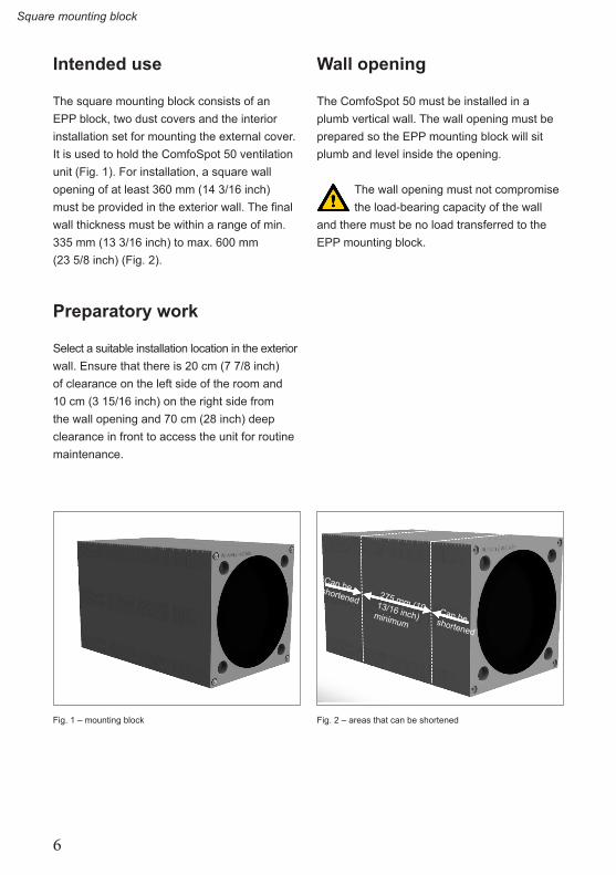
The square mounting block consists of an EPP block, two dust covers and the interior installation set for mounting the external cover. It is used to hold the ComfoSpot 50 ventilation unit (Fig. 1). For installation, a square wall opening of at least 360 mm (14 3/16 inch) must be provided in the exterior wall. The final wall thickness must be within a range of min. 335 mm (13 3/16 inch) to max. 600 mm (23 5/8 inch) (Fig. 2).
Preparatory work
Select a suitable installation location in the exterior wall. Ensure that there is 20 cm (7 7/8 inch) of clearance on the left side of the room and 10 cm (3 15/16 inch) on the right side from the wall opening and 70 cm (28 inch) deep clearance in front to access the unit for routine maintenance.
Wall opening
The ComfoSpot 50 must be installed in a plumb vertical wall. The wall opening must be prepared so the EPP mounting block will sit plumb and level inside the opening.
The wall opening must not compromise the load-bearing capacity of the wall
and there must be no load transferred to the EPP mounting block.
Fig. 1 – mounting block Fig. 2 – areas that can be shortened
Can be shortenedCan be shortened
275 mm (10 13/16 inch) minimum
7
Square mounting block
Installation of the mounting block
The location of the ComfoSpot 50 must meet all local and national code
requirements. Ensure that proper clearance is provided to other fixtures in bathrooms or other "wet" rooms.
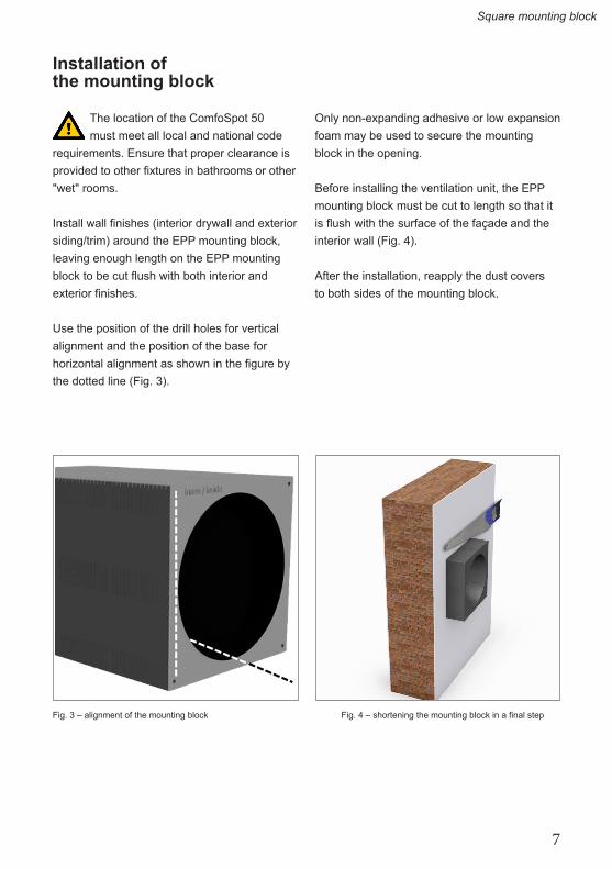
Install wall finishes (interior drywall and exterior siding/trim) around the EPP mounting block, leaving enough length on the EPP mounting block to be cut flush with both interior and exterior finishes.
Use the position of the drill holes for vertical alignment and the position of the base for horizontal alignment as shown in the figure by the dotted line (Fig. 3).
Only non-expanding adhesive or low expansion foam may be used to secure the mounting block in the opening.
Before installing the ventilation unit, the EPP mounting block must be cut to length so that it is flush with the surface of the façade and the interior wall (Fig. 4). After the installation, reapply the dust covers to both sides of the mounting block.
Fig. 3 – alignment of the mounting block Fig. 4 – shortening the mounting block in a final step
8
Tube de montage mural carré
Utilisation prévue
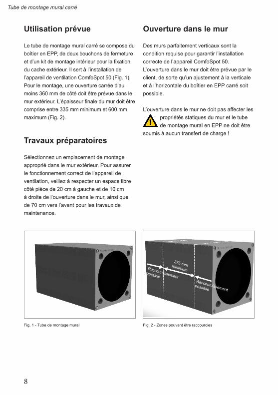
Le tube de montage mural carré se compose du boîtier en EPP, de deux bouchons de fermeture et d’un kit de montage intérieur pour la fixation du cache extérieur. Il sert à l’installation de l’appareil de ventilation ComfoSpot 50 (Fig. 1). Pour le montage, une ouverture carrée d’au moins 360 mm de côté doit être prévue dans le mur extérieur. L’épaisseur finale du mur doit être comprise entre 335 mm minimum et 600 mm maximum (Fig. 2).
Travaux préparatoires
Sélectionnez un emplacement de montage approprié dans le mur extérieur. Pour assurer le fonctionnement correct de l’appareil de ventilation, veillez à respecter un espace libre côté pièce de 20 cm à gauche et de 10 cm à droite de l’ouverture dans le mur, ainsi que de 70 cm vers l’avant pour les travaux de maintenance.
Ouverture dans le mur
Des murs parfaitement verticaux sont la condition requise pour garantir l’installation correcte de l’appareil ComfoSpot 50. L’ouverture dans le mur doit être prévue par le client, de sorte qu’un ajustement à la verticale et à l’horizontale du boîtier en EPP carré soit possible.
L’ouverture dans le mur ne doit pas affecter les propriétés statiques du mur et le tube de montage mural en EPP ne doit être
soumis à aucun transfert de charge !
Fig. 1 - Tube de montage mural Fig. 2 - Zones pouvant être raccourcies
Raccourcissement possible
Raccourcissement possible
275 mm minimum
9
Tube de montage mural carré
Installation du tube de montage mural
Dans les locaux humides, l’appareil ne doit être installé qu’en dehors des
zones de protection 1 et 2 selon la norme DIN 57100/VDE 100 Partie 701 !
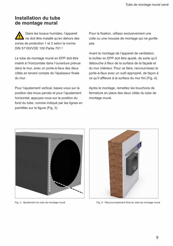
Le tube de montage mural en EPP doit être inséré à l’horizontale dans l’ouverture prévue dans le mur, avec un porte-à-faux des deux côtés en tenant compte de l’épaisseur finale du mur.
Pour l’ajustement vertical, basez-vous sur la position des trous percés et pour l’ajustement horizontal, appuyez-vous sur la position du fond du tube, comme indiqué par les lignes en pointillés sur la figure (Fig. 3).
Pour la fixation, utilisez exclusivement une colle ou une mousse de montage qui ne gonfle pas.
Avant le montage de l’appareil de ventilation, le boîtier en EPP doit être ajusté, de sorte qu’il débouche à fleur de la surface de la façade et du mur intérieur. Pour ce faire, raccourcissez le porte-à-faux avec un outil approprié, de façon à ce qu’il affleure à la surface du mur fini (Fig. 4). Après le montage, remettez les bouchons de fermeture en place des deux côtés du tube de montage mural.
Fig. 3 - Ajustement du tube de montage mural Fig. 4 - Raccourcissement final du tube de montage mural
10
Tubo quadrato per montaggio a parete
Impiego previsto
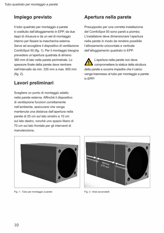
Il tubo quadrato per montaggio a parete è costituito dall’alloggiamento in EPP, da due tappi di chiusura e da un set di montaggio interno per fissare la mascherina esterna. Serve ad accogliere il dispositivo di ventilazione ComfoSpot 50 (fig. 1). Per il montaggio bisogna prevedere un’apertura quadrata di almeno 360 mm di lato nella parete perimetrale. Lo spessore finale della parete deve rientrare nell’intervallo da min. 335 mm a max. 600 mm (fig. 2).
Lavori preliminari
Scegliere un punto di montaggio adatto nella parete esterna. Affinché il dispositivo di ventilazione funzioni correttamente nell’ambiente, assicurarsi che venga mantenuta una distanza dall’apertura nella parete di 20 cm sul lato sinistro e 10 cm sul lato destro, nonché uno spazio libero di 70 cm sul lato frontale per gli interventi di manutenzione.
Apertura nella parete
Presupposto per una corretta installazione del ComfoSpot 50 sono pareti a piombo. L’installatore deve dimensionare l’apertura nella parete in modo da rendere possibile l’allineamento orizzontale e verticale dell’alloggiamento quadrato in EPP.
L’apertura nella parete non deve compromettere la statica della struttura
della parete e occorre impedire che il carico venga trasmesso al tubo per montaggio a parete in EPP!
Fig. 1 - Tubo per montaggio a parete Fig. 2 - Aree accorciabili
Accorciabile
Accorciabile
Minimo 275 mm

11
Tubo quadrato per montaggio a parete
Installazione del tubo per montaggio a parete
In ambienti umidi, installare l’apparecchio solo all’esterno delle aree di protezione
delle zone 1 e 2 a norma DIN 57100/VDE100 parte 701!
Durante la costruzione del muro, inserire il tubo per montaggio a parete in EPP orizzontalmente nell’apertura prevista nella parete, tenendo conto dello spessore finale della parete e lasciandolo sporgere da entrambi i lati.
Per l’allineamento verticale orientarsi rispetto alla posizione dei fori e per quello orizzontale rispetto alla posizione dell’asse del tubo, rappresentato nella figura con una linea tratteggiata (fig. 3).
Per il fissaggio usare esclusivamente colla che non si gonfi o schiuma di montaggio!
Prima di montare il dispositivo di ventilazione, adattare l'alloggiamento in EPP in modo che chiuda a raso con la superficie della facciata o della parete interna. Per farlo, accorciare ciascuna sporgenza a filo con la superficie della parete finita servendosi di un attrezzo adatto (fig. 4). Dopo il montaggio, riapplicare i tappi di chiusura alle due estremità del tubo per montaggio a parete.
Fig. 3 - Allineamento del tubo per montaggio a parete Fig. 4 - Accorciamento finale del tubo per montaggio a parete
12
Mantelbuis vierkant
Gebruiksdoel
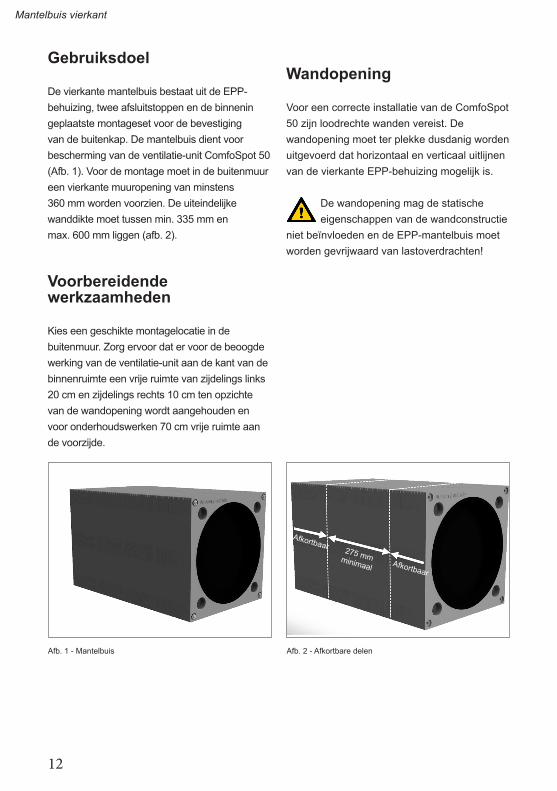
De vierkante mantelbuis bestaat uit de EPP-behuizing, twee afsluitstoppen en de binnenin geplaatste montageset voor de bevestiging van de buitenkap. De mantelbuis dient voor bescherming van de ventilatie-unit ComfoSpot 50 (Afb. 1). Voor de montage moet in de buitenmuur een vierkante muuropening van minstens 360 mm worden voorzien. De uiteindelijke wanddikte moet tussen min. 335 mm en max. 600 mm liggen (afb. 2).
Voorbereidende werkzaamheden
Kies een geschikte montagelocatie in de buitenmuur. Zorg ervoor dat er voor de beoogde werking van de ventilatie-unit aan de kant van de binnenruimte een vrije ruimte van zijdelings links 20 cm en zijdelings rechts 10 cm ten opzichte van de wandopening wordt aangehouden en voor onderhoudswerken 70 cm vrije ruimte aan de voorzijde.
Wandopening
Voor een correcte installatie van de ComfoSpot 50 zijn loodrechte wanden vereist. De wandopening moet ter plekke dusdanig worden uitgevoerd dat horizontaal en verticaal uitlijnen van de vierkante EPP-behuizing mogelijk is.
De wandopening mag de statische eigenschappen van de wandconstructie
niet beïnvloeden en de EPP-mantelbuis moet worden gevrijwaard van lastoverdrachten!
Afb. 1 - Mantelbuis Afb. 2 - Afkortbare delen
Afkortbaar
Afkortbaar
275 mm minimaal

13
Mantelbuis vierkant
Installatie van de mantelbuis
De unit mag in vochtige ruimtes uitsluitend buiten beschermde
omgevingen van de zones 1 en 2 volgens DIN 57100/VDE100 deel 701 worden geïnstalleerd!
De EPP-mantelbuis moet in het kader van de wandopbouw horizontaal met uitstekend deel aan beide zijden in de voorziene wandopening worden geplaatst, rekening houdend met de uiteindelijke wanddikte.
Tijdens het verticaal uitlijnen kunt u zich baseren op de positie van de boorgaten; voor het horizontaal uitlijnen baseert u zich op de positie van de buisbodem, zoals in de afbeelding met stippellijn aangegeven (afb. 3).
Voor de bevestiging mag uitsluitend niet-zwellende lijm of montageschuim worden gebruikt!
Voor de inbouw van de ventilatie-unit moet de EPP-behuizing dusdanig worden aangepast dat deze gelijk met het oppervlak van de gevel of de binnenmuur afsluit. Daartoe moet het uitstekende deel met een geschikt gereedschap worden afgekort, zodat dit op één lijn ligt met de afgewerkte wand (afb. 4). Plaats de afsluitstoppen na de montage aan beide zijden terug op de mantelbuis.
Afb. 3 - Uitlijnen van de mantelbuis Afb. 4 - Mantelbuis definitief afkorten

14
Przejście kwadratowe do montażu w ścianie
Przeznaczenie
Przejście kwadratowe do montażu w ścianie składa się z obudowy EPP, dwóch zaślepek i zewnętrznego zestawu montażowego do mocowania zaślepki zewnętrznej. Służy do mocowania jednostki wentylacyjnej ComfoSpot 50 (rys. 1). W celu montażu należy wykonać w ścianie zewnętrznej kwadratowy otwór (min. 360 mm). Ostateczna grubość ściany powinna wynosić od min. 335 mm do maks. 600 mm (rys. 2).
Przygotowanie
Wybrać odpowiednie miejsce montażu w ścianie zewnętrznej. Zwrócić uwagę na to, że zgodne z przeznaczeniem działanie jednostki wentylacyjnej wymaga, aby w pomieszczeniu zachowany był od otworu w ścianie odstęp 20 cm z boku z lewej strony i 10 cm z boku prawej strony oraz w celu umożliwienia prac konserwacyjnych 70 cm od przodu.
Otwór w ścianie
Warunkiem prawidłowej instalacji urządzenia ComfoSpot 50 jest pionowość ścian. Otwór w ścianie należy wykonać na miejscu w taki sposób, aby możliwe było poziome i pionowe wyrównanie kwadratowej obudowy EPP.
Otwór w ścianie nie może mieć wpływu na właściwości statyczne konstrukcji ściany. Przejście w ścianie powinno być
wolne od obciążeń.
Rys. 1 - Przejście przez ścianę Rys. 2 - Obszary możliwe do skrócenia
Możliwość skróceniaMożliwość skrócenia
Min. 275 mm

15
Przejście kwadratowe do montażu w ścianie
Montaż przejścia przez ścianę
Przejście PCV można instalować w pomieszczeniach wilgotnych tylko
poza obszarami chronionymi stref 1 i 2 według DIN 57100/VDE100 część 701!
Przejście kwadratowe należy włożyć w trakcie budowy poziomo do odpowiedniego otworu w ścianie, uwzględniając końcową grubość ściany, z obustronnym nadmiarem.
Podczas ustawiania w pionie należy orientować się według otworów, natomiast podczas wyrównywanie z poziomie według położenia spodu rury, jak pokazano na rysunku za pomocą przerywanej linii (rys. 3).
Do zamocowania można stosować wyłącznie niepęczniejące kleje lub piankę montażową!
Przed zamontowaniem jednostki wentylacyjnej należy dopasować obudowę EPP w taki sposób, aby leżała w jednej płaszczyźnie z elewacją lub ścianą wewnętrzną. W związku z tym wystającą część należy skrócić za pomocą odpowiednich narzędzi tak, aby rura leżała w jednej płaszczyźnie z gotową ścianą (rys. 4). Po zakończeniu montażu założyć ponownie zaślepki z obu stron na rurę.
Rys. 3 - Wyrównywanie przejścia do montażu w ścianie Rys. 4 - Skracanie przejścia do montażu w ścianie

GermanyZehnder Group Deutschland GmbHAlmweg 3477933 LahrT +49 7821 586 0F +49 7821 586 [email protected]
France Zehnder Group Services SAS7, rue Jean Mermoz,Courcouronnes / Saint Guénault91031 Evry CedexT +33 169 361 646F +33 169 474 [email protected]
The NetherlandsZehnder Group Nederland B.V.Lingenstraat 28028 PM ZwolleT +31 38 42 96 911F +31 38 42 25 [email protected]
Great BritainZehnder ComfosystemsA division of Zehnder Group UK LtdUnit 1, Brookside AvenueRustington West SussexBN16 3LFT +44 1903 777 333F +44 1903 782 [email protected]
ItalyZehnder Tecnosystems S.r.l.Via XXV Luglio, 6Campogalliano (MO) 41011T +39 059 978 62 00F +39 059 978 62 [email protected]
PolandZehnder Polska Sp. z o.o.ul. Kurpiów 14a52-214 WrocławT +48 71 367 64 24F +48 71 367 64 [email protected]
United StatesZehnder America Inc.540 Portsmouth AvenueGreenland, NH 03840T +1 603 422 6700F +1 603 422 [email protected]
SwitzerlandZehnder ComfosystemsCesovent AGZugerstrasse 1628820 WädenswilT +41 43 833 20 20F +41 43 833 20 [email protected]
Sales InternationalZehnder Group Deutschland GmbHAlmweg 3477933 LahrT +49 7821 586-392F +49 7821 586-406sales.international@zehndergroup.comwww.international.zehnder-systems.com
PD
E_I
nsta
llatio
n N
otes
_CS
50_S
quar
e m
ount
ing
bloc
k_V
1.0,
V11
18_D
E,E
N,F
R,IT
,NL,
PL_
subj
ect t
o ch
ange


![MON ÉCOLE, UN ESPACE DE QUALITÉ...régional [1], le Gouvernement a chargé le Service École de développer un guide permettant d’apprécier la qualité de ces infrastructures](https://static.fdocuments.pl/doc/165x107/602275302e5cb52edf181080/mon-cole-un-espace-de-qualit-rgional-1-le-gouvernement-a-charg-le.jpg)