C lib tiCalibration off ththe 6-CtComponent ...
1
HOCHSCHULE HOCHSCHULE REGENSBURG U N I V E R S I T Y O F A P P L I E D S C I E N C E S S C I E N C E S C lib ti f th 6 C t Bl f th RWT Calibration of the 6-Component-Balance of the RWT Calibration of the 6 Component Balance of the RWT with Compensation of Interferences with Compensation of Interferences Riebl, Thomas e-mail: dereinzug@arcor de Riebl, Thomas e mail: [email protected] Mechanical Engineering, Galgenbergstr . 30, 93053 Regensburg (Germany), Head: Prof. Dr.-Ing. Stephan Lämmlein http://www.hs-regensburg.de/fk/m/labore/562.php 3 Measuring signals Æ physical values 1. Determination of all 6 components 3. Measuring signals Æ physical values 1. Determination of all 6 components Beside the three forces in the area the three moments (roll yaw and pitch moment) Due to deformations in the balance a 0 0007 Beside the three forces in the area the three moments (roll, yaw and pitch moment) h t b d t Th f 6 C t Bl i dd A th Due to deformations in the balance a f i X di ti d l 0,0006 0,0007 have to be measured, too. Therefore a 6-Component-Balance is needed. As the name i li thi d i i bl t t th d i l d t th 6 t force in X-direction produces also a i i l i th f th Z 0,0005 implies this device is able to separate the aerodynamic loads to the 6 components. measuring signal in the sensor for the Z- 0 0003 0,0004 V/V] These values can be defined in the coordinate system which is fixed to the vehicle direction (nonlinear curve). This is called 0 0002 0,0003 x Fz [m (Fig. 1). This coordinate system is equivalent to the one which is used in vehicle interference or crosstalk of a load. It is 0,0001 0,0002 x dynamics [ADA94]. For this reason it is possible to use data from the wind tunnel with calculated about x Fx , how big the 0 the right algebraic sign directly for vehicle dynamics analysis [ADA94]. Fx interference share in the signal is. Then -0,0001 0,00 0,05 0,10 0,15 0,20 the right algebraic sign directly for vehicle dynamics analysis [ADA94]. interference share in the signal is. Then the force is calculated by multiplication of 0,00 0,05 0,10 0,15 0,20 x Fx [mV/V] the force is calculated by multiplication of the rectified signal with the sensitivity of Fi 5 I t f t th F ith l d i the rectified signal with the sensitivity of the sensor Fig. 5: Interference at the F Z -sensor with load in X-direction the sensor . X direction 2 2 ( ) 1 ( ) ( -(a a )) Zb F F F F F F F F F s x x x = ⋅ ⋅ + ⋅ , 2 ( ) 1 ( ) ( (a a )) Z Z Z X X Z X X Z ba F F F F F F F F F s x x x + .5 according to the curve in Fig The conversion from the measuring signals to the three forces and three moments in The conversion from the measuring signals to the three forces and three moments in the balance coordinate system with compensation of interferences can be declared the balance coordinate system with compensation of interferences can be declared with an interpretation matrix as follows: with an interpretation matrix as follows: ⎡ ⎤⎡ ⎤ , X F X ba s F s F ⎡ ⎤ ⎢ ⎥ ⎢ ⎥ 0 0 0 0 0 0 0 0 0 0 X F x x ⎡ ⎤⎡ ⎤ ⎢ ⎥⎢ ⎥ ⎢ ⎥⎢ ⎥ ⎢ ⎥⎢ ⎥ , ( ) ( ) ( ) Y F Y ba F F F F F F F Zb s F s a x a s F ⎢ ⎥ ⎢ ⎥ ⎢ ⎥ − ⋅ ⋅ + ⎢ ⎥ 2 1 0 0 0 0 0 0 0 0 0 Y F F x x ⎢ ⎥⎢ ⎥ ⎢ ⎥⎢ ⎥ ⎢ ⎥⎢ ⎥ ⎢ ⎥⎢ ⎥ Fig. 1: Location and alignment of the vehicle mounted coordinate system according to [ADA94] ( ) ( ) , , ( ) ( ) ( ) Z Z X X Z X Z X X X X Y X X Z X X F F F F F F F Z ba X ba M M F M F M M F M M F M s a k s k s s ⎢ ⎥ = ⎢ ⎥ − ⋅ − ⋅ − ⋅ ⎢ ⎥ ⎢ ⎥ 2 1 1 0 0 Z X F M x ⎢ ⎥⎢ ⎥ ⋅ ⎢ ⎥⎢ ⎥ ⎢ ⎥⎢ ⎥ ⎢ ⎥⎢ ⎥ , ( ) ( ) Y X Y Y Z Y Y Y ba M F M M F M M M k s k s s M ⎢ ⎥ ⎢ ⎥ − ⋅ − ⋅ ⎢ ⎥ ⎢ ⎥ 0 0 0 Y M x ⎢ ⎥⎢ ⎥ ⎢ ⎥⎢ ⎥ ⎢ ⎥⎢ ⎥ ⎢ ⎥⎢ ⎥ At the laboratory „Windkanal/Strömungsmesstechnik“ (LWS) of the University of , ( ) ( ) Z X Z Z Y Z ba M F M M F M k s k ⎢ ⎥ ⎣ ⎦ − ⋅ − Z Z Z M M M s s x ⎢ ⎥⎢ ⎥ ⎢ ⎥⎢ ⎥ ⋅ ⎣ ⎦⎣ ⎦ 0 0 0 Applied Sciences Regensburg a diploma thesis was performed, in which a 6- The mean diagonal is filled with the sensitivities of the sensors. The orange marked Component-Balance was configured, designed and built. Before this balance can be The mean diagonal is filled with the sensitivities of the sensors. The orange marked secondary diagonal elements are used for conversion of the moments to the axis of used, it has to be calibrated. In the process the characteristic curves will be recorded secondary diagonal elements are used for conversion of the moments to the axis of the balance coordinate system The purple tagged ones are used for compensation of used, it has to be calibrated. In the process the characteristic curves will be recorded and the sensitivities and existing interferences will be identified the balance coordinate system. The purple tagged ones are used for compensation of interferences at the sensors for F and M and the sensitivities and existing interferences will be identified. interferences at the sensors for F Z and M X . 4 Measurements with the Ahmed body 2 Calibration of the 6 Component Balance 4. Measurements with the Ahmed-body 2. Calibration of the 6-Component-Balance It i t h k id t l d ltd t t hi b There is a lack of force measurement standards. That‘s why mass measurement It is common to check wind tunnels and related measurement technique by t ith f dl (t t ) Th dl h l d b standards are used for calibration [PMT08]. Forces in all three directions are required. measurements with reference models (test case). These models have already been But the weight only acts in the direction of the acceleration of gravitiy . Deflection rollers measured in several wind tunnels. Therefore there is a wide database. Additional to can‘t be used, because the friction in the bearings causes characteristic curves with the calibration a measurement with a model (scale 1:5) of the Ahmed-body (generic can t be used, because the friction in the bearings causes characteristic curves with hysteresis Therefore the orientation of the balance will be shifted relative to the model of a car) was executed in the wind tunnel (called RWT). hysteresis. Therefore the orientation of the balance will be shifted relative to the acceleration of gravitity according to the desired load direction acceleration of gravitity according to the desired load direction. X X Z Fi 7 D l i f th d ffi i t th F Y Fig. 7: Developing of the drag coefficient over the Reynolds‘ number Z F X Y Fi 3 F i ti X di ti f th bl di t t Fig. 6: Model of the Ahmed-body in the ¾-open testsection of the RWT (balance underneath the road) Reynolds number Fig. 3: Force in negative X-direction of the balance coordinate system of the RWT (balance underneath the road) Y X For a Reynolds‘ number of 600 000 the RWT measurement produced the following X For a Reynolds number of 600.000 the RWT measurement produced the following data of the Ahmed body: F Z data of the Ahmed-body: Drag coefficient C = 0 297 Drag coefficient Lift ffi i t C D = 0,297 C 0 309 Y Lift coefficient ff C L = 0,309 C 0 024 Fig 2: Force in negative Z direction of the Pitch moment coefficient C M = -0,024 X Fig. 2: Force in negative Z-direction of the balance coordinate system A comparison with results from a reference measurement in another wind tunnel X Z A comparison with results from a reference measurement in another wind tunnel (DFVLR) i diffi lt b th R ld ‘ b i ifi tl hi h F (DFVLR) is difficult, because the Reynolds‘ number was significantly higher (4 450 000) Th d ffi i t hi h i d i th RWT i 2 5% hi h Th F Y (4.450.000). The drag coefficient, which is measured in the RWT, is 2.5% higher . The lift and the pitch moment are showing bigger differences, but the tendencies are Fig. 4: Force in negative Y -direction of the balance coordinate system correct. Rf [ADA94] HUCHO W H A d ik d At bil Dü ld f Vi 1994 References: [ADA94] HUCHO, W.-H.: Aerodynamik des Automobils. Düsseldorf: Vieweg 1994 [PMT08] LÄMMLEIN, S.: Unterlagen zum PMT -Versuch KW – Kalibrierung Kraftwaage. HS Regensburg 2008 [PMT08] LÄMMLEIN, S.: Unterlagen zum PMT Versuch KW Kalibrierung Kraftwaage. HS Regensburg 2008
Transcript of C lib tiCalibration off ththe 6-CtComponent ...
HOCHSCHULEHOCHSCHULEREGENSBURGUNIVERSITYO F A PP L I E DS C I E N C E SS C I E N C E S
C lib ti f th 6 C t B l f th RWTCalibration of the 6-Component-Balance of the RWTCalibration of the 6 Component Balance of the RWTwith Compensation of Interferenceswith Compensation of Interferences
Riebl, Thomas e-mail: dereinzug@arcor deRiebl, Thomas e mail: [email protected] Engineering, Galgenbergstr. 30, 93053 Regensburg (Germany), Head: Prof. Dr.-Ing. Stephan Lämmlein http://www.hs-regensburg.de/fk/m/labore/562.phpg g, g g , g g ( y), g p p g g p p
3 Measuring signals physical values1. Determination of all 6 components 3. Measuring signals physical values1. Determination of all 6 componentsBeside the three forces in the area the three moments (roll yaw and pitch moment) Due to deformations in the balance a 0 0007Beside the three forces in the area the three moments (roll, yaw and pitch moment)h t b d t Th f 6 C t B l i d d A th
Due to deformations in the balance af i X di ti d l 0,0006
0,0007
have to be measured, too. Therefore a 6-Component-Balance is needed. As the namei li thi d i i bl t t th d i l d t th 6 t
force in X-direction produces also ai i l i th f th Z
0,0005
,
implies this device is able to separate the aerodynamic loads to the 6 components. measuring signal in the sensor for the Z-0 0003
0,0004
V/V
]
These values can be defined in the coordinate system which is fixed to the vehicle direction (nonlinear curve). This is called 0 0002
0,0003
x Fz[m
(Fig. 1). This coordinate system is equivalent to the one which is used in vehicle interference or crosstalk of a load. It is 0,0001
0,0002x( g ) y qdynamics [ADA94]. For this reason it is possible to use data from the wind tunnel with calculated about xFx, how big the 0y [ ] pthe right algebraic sign directly for vehicle dynamics analysis [ADA94].
Fx, ginterference share in the signal is. Then
-0,00010,00 0,05 0,10 0,15 0,20the right algebraic sign directly for vehicle dynamics analysis [ADA94]. interference share in the signal is. Then
the force is calculated by multiplication of0,00 0,05 0,10 0,15 0,20
xFx[mV/V]the force is calculated by multiplication ofthe rectified signal with the sensitivity of Fi 5 I t f t th F ith l d i the rectified signal with the sensitivity ofthe sensor
Fig. 5: Interference at the FZ-sensor with load in X-directionthe sensor. X direction
22 ( ) 1 ( )( - (a a ))Z b F F F F F F F FF s x x x= ⋅ ⋅ + ⋅, 2 ( ) 1 ( )( (a a ))
Z Z Z X X Z X XZ ba F F F F F F F FF s x x x+. 5according to the curve in Fig
The conversion from the measuring signals to the three forces and three moments inThe conversion from the measuring signals to the three forces and three moments inthe balance coordinate system with compensation of interferences can be declaredthe balance coordinate system with compensation of interferences can be declaredwith an interpretation matrix as follows:with an interpretation matrix as follows:
⎡ ⎤ ⎡ ⎤,
XFX ba
sFsF
⎡ ⎤⎢ ⎥⎢ ⎥
0 0 0 0 0
0 0 0 0 0XF
x
x
⎡ ⎤ ⎡ ⎤⎢ ⎥ ⎢ ⎥⎢ ⎥ ⎢ ⎥⎢ ⎥ ⎢ ⎥,
( ) ( )( )YFY ba
F F F F F F FZ b
sFs a x a sF
⎢ ⎥⎢ ⎥⎢ ⎥ − ⋅ ⋅ +⎢ ⎥ 2 1
0 0 0 0 0
0 0 0 0YF
F
x
x⎢ ⎥ ⎢ ⎥⎢ ⎥ ⎢ ⎥⎢ ⎥ ⎢ ⎥⎢ ⎥ ⎢ ⎥Fig. 1: Location and alignment of the vehicle mounted coordinate system according to [ADA94]
( ) ( ),
, ( ) ( ) ( )
( )Z Z X X Z X Z
X X X X Y X X Z X X
F F F F F F FZ ba
X ba M M F M F M M F M M
F
M s a k s k s s
+⎢ ⎥ =⎢ ⎥ − ⋅ − ⋅ − ⋅⎢ ⎥⎢ ⎥
2 1
1 0 0Z
X
F
Mx⎢ ⎥ ⎢ ⎥⋅⎢ ⎥ ⎢ ⎥⎢ ⎥ ⎢ ⎥⎢ ⎥ ⎢ ⎥
, ( ) ( )Y X Y Y Z Y YY ba M F M M F M M
M k s k s sM
⎢ ⎥⎢ ⎥ − ⋅ − ⋅⎢ ⎥⎢ ⎥
0 0 0YM
x⎢ ⎥ ⎢ ⎥⎢ ⎥ ⎢ ⎥⎢ ⎥ ⎢ ⎥⎢ ⎥ ⎢ ⎥At the laboratory „Windkanal/Strömungsmesstechnik“ (LWS) of the University of ,
( ) ( )Z X Z Z Y
Z baM F M M F
M k s k⎢ ⎥⎣ ⎦ − ⋅ −Z Z ZM M Ms s x
⎢ ⎥ ⎢ ⎥⎢ ⎥ ⎢ ⎥⋅⎣ ⎦ ⎣ ⎦0 0 0
Applied Sciences Regensburg a diploma thesis was performed, in which a 6- The mean diagonal is filled with the sensitivities of the sensors. The orange markedpp g g p p ,Component-Balance was configured, designed and built. Before this balance can be
The mean diagonal is filled with the sensitivities of the sensors. The orange markedsecondary diagonal elements are used for conversion of the moments to the axis ofp g , g
used, it has to be calibrated. In the process the characteristic curves will be recordedsecondary diagonal elements are used for conversion of the moments to the axis ofthe balance coordinate system The purple tagged ones are used for compensation ofused, it has to be calibrated. In the process the characteristic curves will be recorded
and the sensitivities and existing interferences will be identifiedthe balance coordinate system. The purple tagged ones are used for compensation ofinterferences at the sensors for F and Mand the sensitivities and existing interferences will be identified. interferences at the sensors for FZ and MX.
4 Measurements with the Ahmed body 2 Calibration of the 6 Component Balance 4. Measurements with the Ahmed-body 2. Calibration of the 6-Component-BalanceIt i t h k i d t l d l t d t t h i bThere is a lack of force measurement standards. That‘s why mass measurement It is common to check wind tunnels and related measurement technique by
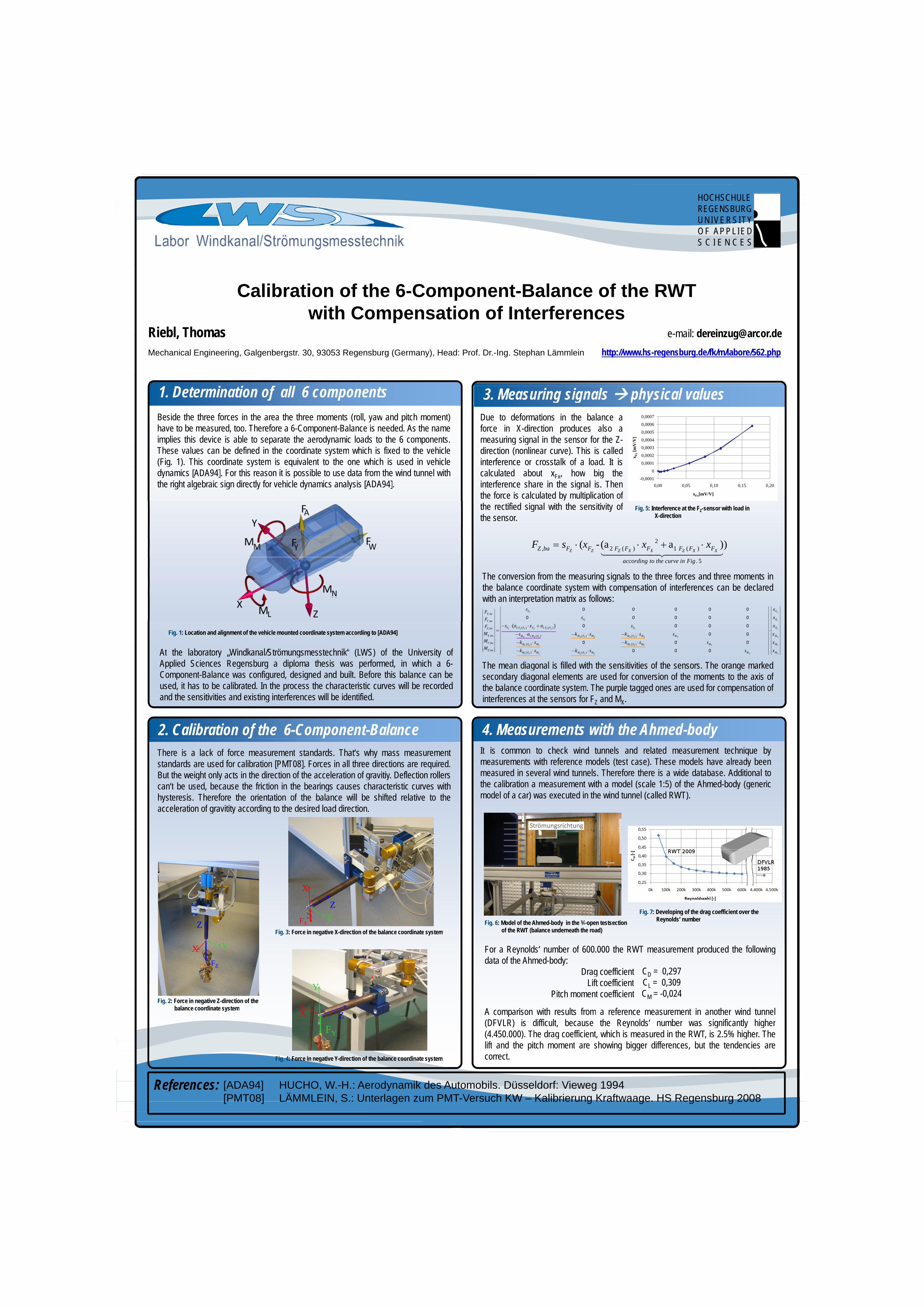
t ith f d l (t t ) Th d l h l d bstandards are used for calibration [PMT08]. Forces in all three directions are required. measurements with reference models (test case). These models have already been[ ] qBut the weight only acts in the direction of the acceleration of gravitiy. Deflection rollers measured in several wind tunnels. Therefore there is a wide database. Additional tog y g ycan‘t be used, because the friction in the bearings causes characteristic curves with the calibration a measurement with a model (scale 1:5) of the Ahmed-body (genericcan t be used, because the friction in the bearings causes characteristic curves withhysteresis Therefore the orientation of the balance will be shifted relative to the
( ) y (gmodel of a car) was executed in the wind tunnel (called RWT).hysteresis. Therefore the orientation of the balance will be shifted relative to the
acceleration of gravitity according to the desired load direction) ( )
acceleration of gravitity according to the desired load direction.
XX
ZFi 7 D l i f th d ffi i t th
F YFig. 7: Developing of the drag coefficient over the
Reynolds‘ numberZ FX
YFi 3 F i ti X di ti f th b l di t t
Fig. 6: Model of the Ahmed-body in the ¾-open testsectionof the RWT (balance underneath the road)
Reynolds number
Fig. 3: Force in negative X-direction of the balance coordinate system of the RWT (balance underneath the road)
YX For a Reynolds‘ number of 600 000 the RWT measurement produced the followingX For a Reynolds number of 600.000 the RWT measurement produced the followingdata of the Ahmed body:FZdata of the Ahmed-body:
Drag coefficient C = 0 297Drag coefficientLift ffi i t
CD = 0,297C 0 309Y Lift coefficient
ffCL = 0,309C 0 024
Fig 2: Force in negative Z direction of thePitch moment coefficient CM = -0,024
XFig. 2: Force in negative Z-direction of the
balance coordinate system A comparison with results from a reference measurement in another wind tunnelX Zy A comparison with results from a reference measurement in another wind tunnel
(DFVLR) i diffi lt b th R ld ‘ b i ifi tl hi hF (DFVLR) is difficult, because the Reynolds‘ number was significantly higher(4 450 000) Th d ffi i t hi h i d i th RWT i 2 5% hi h ThFY (4.450.000). The drag coefficient, which is measured in the RWT, is 2.5% higher. Thelift and the pitch moment are showing bigger differences, but the tendencies are
Fig. 4: Force in negative Y-direction of the balance coordinate system correct.g g y
R f [ADA94] HUCHO W H A d ik d A t bil Dü ld f Vi 1994References: [ADA94] HUCHO, W.-H.: Aerodynamik des Automobils. Düsseldorf: Vieweg 1994[PMT08] LÄMMLEIN, S.: Unterlagen zum PMT-Versuch KW – Kalibrierung Kraftwaage. HS Regensburg 2008[PMT08] LÄMMLEIN, S.: Unterlagen zum PMT Versuch KW Kalibrierung Kraftwaage. HS Regensburg 2008