
ACCEPTED MANUSCRIPT - uwm.edu.pl · PDF fileconsists of singular registers B ... decomposition...
12
Correspondence: Tomasz Mazurkiewicz, Instytut Matematyki i Kryptologii, Wydział Cybernetyki, Wojskowa Akademia Techniczna, ul. Kaliskiego 2, 00-909 Warszawa, email: [email protected] ACCEPTED MANUSCRIPT Title: AN EFFICIENT HARDWARE IMPLEMENTATION OF A COMBINATIONS GENERATOR Author: Tomasz Mazurkiewicz To appear in: Technical Sciences Received 14 September 2017; Accepted 24 September 2017; Available online 2 October 2017. This is a PDF file of an unedited manuscript that has been accepted for publication. As a service to our customers we are providing this early version of the manuscript. The manuscript will undergo copyediting, typesetting, and review of the resulting proof before it is published in its final form. Please note that during the production process errors may be discovered which could affect the content, and all legal disclaimers that apply to the journal pertain.
Transcript of ACCEPTED MANUSCRIPT - uwm.edu.pl · PDF fileconsists of singular registers B ... decomposition...
Correspondence: Tomasz Mazurkiewicz, Instytut Matematyki i Kryptologii, Wydział
Cybernetyki, Wojskowa Akademia Techniczna, ul. Kaliskiego 2, 00-909 Warszawa, email:
ACCEPTED MANUSCRIPT
Title: AN EFFICIENT HARDWARE IMPLEMENTATION OF A COMBINATIONS
GENERATOR
Author: Tomasz Mazurkiewicz
To appear in: Technical Sciences
Received 14 September 2017;
Accepted 24 September 2017;
Available online 2 October 2017.
This is a PDF file of an unedited manuscript that has been accepted for publication. As a service
to our customers we are providing this early version of the manuscript. The manuscript will
undergo copyediting, typesetting, and review of the resulting proof before it is published in its
final form. Please note that during the production process errors may be discovered which could
affect the content, and all legal disclaimers that apply to the journal pertain.
AN EFFICIENT HARDWARE IMPLEMENTATION OF
A COMBINATIONS GENERATOR
Tomasz Mazurkiewicz1
1 Faculty of Cybernetics, Military University of Technology
Abstract
In this paper an area-efficient hardware implementation of a Bincombgen algorithm was presented. This
algorithm generates all (n,k) combinations in the form of binary vectors. The generator was implemented using
Verilog language and synthesized using Xilinx and Intel-Altera software. Some changes were applied to the original
code, which allows our FPGA implementation to be more efficient than in the previously published paper. The usage
of chip resources and maximum clock frequency for different values of n and k parameters are presented.
Keywords: information technology, generator of combinations, field programmable gate arrays
Introduction
The generation of combinatorial patterns is a well-known problem. Knuth (2006) traces
the history of this problem back to ancient China, India and Greece. Generation of (n,k)
combinations has received much attention over the last couple of decades. Several algorithms
were published in the 1960s. In those days a number of Lehmer articles (1960, 1964) attracted
considerable interest. Since then, a number of algorithms were proposed (AKL 1987, CHEN and
CHERN 1966, HOUGH and RUSKEY 1988, RUSKEY and WILLIAMS 2009, STOJMENOVIC
1992, TAKAOKA 1999, WEI 2014). Various applications of generators of combinations were
found, e.g. parallel processing of combinatorial problems (KOKOSIŃSKI 1997b).
Kokosinski (1997a) proposed two algorithms called Combgen and Bincombgen. Both
algorithms generate all (n,k) combinations using different combination representation:
respectively conventional and binary. Especially the second one can be used to perform hardware
mask/comparand vector generation efficiently.
This paper describes an efficient hardware implementation of Bincombgen algorithm.
A basic model was implemented, which generates 1 combination per clock cycle. It takes (𝑛𝑘)
clock cycles to generate all (n,k) combinations. We have obtained satisfactory results
demonstrating that the generator can be efficiently implemented in a FPGA device. Our results
are also compared to the results presented by Bubniak et al. (2004).
This paper is organized as follows. In the next section Bincombgen algorithm for
generation of combinations is presented. In the third section details of its hardware
implementation are described. Our results are compared to the results in the literature in Section
4. The last section contains a summary.
The algorithm description
Algorithm Bincombgen generates all (n,k) combinations in the form of n-bit binary
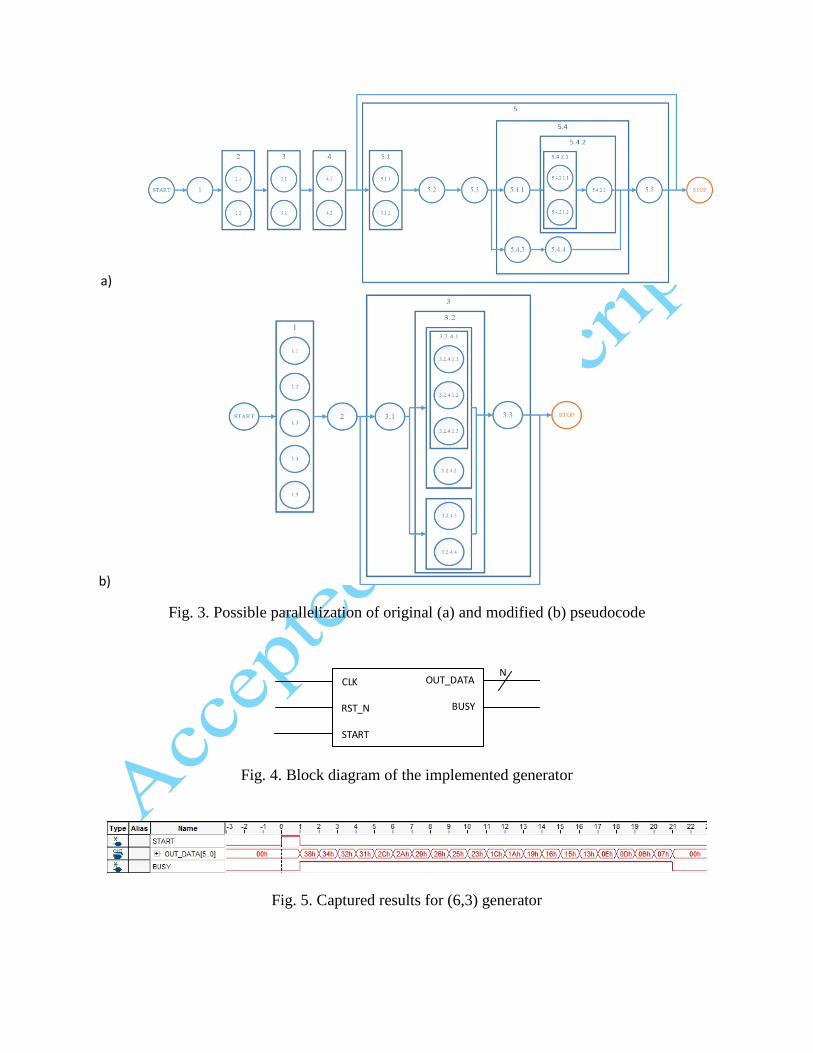
vectors. A pseudocode of the algorithm is presented in Fig. 1. Vectors are generated in a reverse
lexicographic order in constant time per combination. In this paper some changes to the original
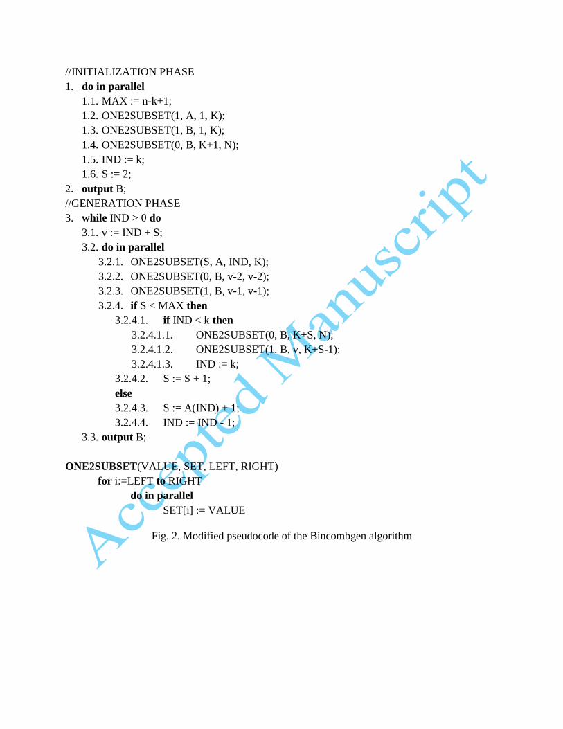
algorithm were made to simplify hardware implementation. A modified pseudocode of the
algorithm is presented in Fig. 2. The order of operations as well as subsets of indexes for
ONE2SUBSET operations have been changed. The potential gain on parallelization was presented
in Fig. 3. Operations in the same column can be done in parallel. Proposed modifications allows
all operations in the generation phase to be performed in the same clock cycle in hardware
implementation. It is possible since 3.1 and 3.3 operations can be done using combinatorial logic.
Table A and B are initialized at the same time. Table A is initialized by setting all (k)
elements to 1. In the table B the first k bits are set to 1, while others (n-k) are set to 0. This value
will be used to generate first output vector. For example, if n = 6 and k = 3 the first generated
vector will be 111000. At the same time S and IND registers are initialized. Initialization phase
can be done in parallel (i.e. in one clock cycle).
In the generation phase values of A, B, S and IND change in parallel on the edge of CLK
signal. All modifications of B can be applied in one clock cycle, because subsets of indexes for
ONE2SUBSET operations are disjunctive. Bits from 1 to v-3 are left unchanged. Value of v is
modified by combinational logic. Combinations are generated as long as 𝐼𝑁𝐷 > 0.
Exemplary sequences generated by modified Bincombgen algorithm for n = 6 and k = 3
are presented in Table 1.
Hardware implementation
Algorithm described in the section 2. was implemented using a basic model, which
consists of singular registers B (of size n bits), S and IND and table A of size k. Each element of a
table A is p bit wide, where 𝑝 = ⌈𝑙𝑜𝑔2(𝑀𝐴𝑋)⌉. In this model 1 output vector per clock cycle is
generated. It makes an implementation small and compact and allows the device to work with
high clock frequencies. Both n and k are the inputs of the algorithm, provided to the module as
parameters, which can be modified during module instantiation. Such implementation can also be
easily used to perform efficient hardware mask/comparand vector generation.
In order to compare our results with those described by Bubniak et al. (2004), similar
interface was used (see Fig. 4). There are three input signals: CLK, RST_N and START. The first
one is a clock signal. The second one is used to reset the generator if necessary. This input is
negative-edge triggered. Signal START is used to start computations. In each clock cycle an
output (OUT_DATA) of n bits is produced. Signal BUSY indicates that calculations are in
progress.
Described algorithm was implemented using Verilog language. Created generator of
combinations was tested and verified using ISE Design Suite 14.7, Intel Quartus Prime 16.0 and
ModelSim-Altera 10.4d. Test values were generated using software implementation of described
algorithm that was created in Python.
To verify whether the implementation is producing correct results, the prototypes of the
(6,3) and (20,10) generators were synthesized and loaded onto FPGA devices. Our experiments
were carried out on two development kits:
• Terasic DE2-115 that features Altera (Intel-FPGA) Cyclone IV E device,
• Atlys Trainer Board that features Xilinx Spartan 6 device.
Results for (6,3) generator (implemented on the DE2-115 board), captured using
SignalTap Logic Analyzer, are presented in Fig. 5. Clock frequency for testing purpose was set to
50MHz. All generated sequences are equal to values presented in Table 1.
Generation of the combinations starts when START signal is driven high. In the following
clock cycles consecutive combinations are generated, starting with 111000 (0x38). Output values
change on the positive edge of CLK signal. Signal BUSY remains driven high as long as the
generator produces next vectors. After completion of computations, BUSY is driven to a logical
low and the value of OUT_DATA output is set to 000000. In case when START signal is driven
high once more, all combinations are generated all over again.
Results
Results obtained from synthesis using ISE WebPACK 6.1 for XC2S100 device were
presented by Bubniak et al. (2004). Unfortunately, this device in no longer available in ISE
Design Suite 14.7. Therefore, newer Xilinx Spartan III XC3S50 was chosen as a target device.
This device allows implementation to use up to 1536 4 input LUTs and 768 slices.
Usage of FPGA resources for several values of n and k (k = n / 2) are presented in
Table 2. Additionally, maximum clock frequency was determined.
An implementation described by Bubniak et al. (2004) resulted in a high consumption of
logical resources. Synthesis of generators for n>8 and k>4 was impossible in targeted XC2S100
device due to insufficient FPGA resources. In contradiction with those results, utilization level of
the FPGA resources for our implementation is quite low. It is interesting to note that XC2S100
offers more logic resources than used in this paper XC3S50, i.e.1200 slices and 2400 4 input
LUTs. However, in this paper different target device and newer version of software were used.
Presented results thus need to be interpreted with caution.
In case of the smallest synthesized generator (n = 4, k = 2) around 3% of available
resources is used. In case of the biggest one presented in the referenced literature (n = 20, k = 10)
utilization level does not exceed 25%. Synthesis of (80,40) generator was possible and it did not
exceed the size of the chip.
Summary
Implemented generator of combinations, based on Bincombgen algorithm, generates all
(n,k) combinations in (𝑛𝑘) clock cycles. We have obtained satisfactory results demonstrating that
the generator can be efficiently implemented in a FPGA device. A consumption of logical
resources is quite low and maximum clock frequency is relatively high.
We believe our work will be helpful in a hardware implementation of linear
decomposition algorithm (MAZURKIEWICZ and ŁUBA 2017). The hardware implementation
of this algorithm require generating a discernibility matrix (stored in RAM). Generated values are
then read from the memory and a possible linear decomposition is sought. Generator of
combinations could be used to perform efficient memory addresses generation in this operation,
since all n-bit vectors with Hamming weight equal to 𝑘 ∈ ⟨2, 𝑛⟩ must be generated.
References
AKL, S.G. 1987. Adaptive and Optimal Parallel Algorithms For Enumerating Permutations and
Combinations, The Computer Journal, 30, pp. 433-436
BUBNIAK, G., et al. 2004. A Hardware Implementation of a Generator of (N,K)-Combinations,
IFAC Proceedings Volumes, Vol. 37, No. 20, pp. 228-231
CHEN, G.H., CHERN, M.-S. 1966. Parallel Generation of Permutations and Combinations, BIT
Numerical Mathematics, Vol. 26, Issue 3, pp. 277-283
HOUGH, T., RUSKEY, F. 1988. An Efficient Implementation of the Eades, Hickey, Read
Adjacent Interchange Combination Generation Algorithm, Journal of Combinatorial Mathematics
and Combinatorial Computing, 4, pp. 79-86
KNUTH, D.E. 2006. The Art of Computer Programming, Vol. 4, Fasc. 4, Addison-Wesley
KOKOSIŃSKI, Z. 1997. On Parallel Generation of Combinations in Associative Processor
Architectures, Draft, Proc. of IASTED Int. Conf. on Parallel and Distributed Systems Euro-PDS,
pp. 283-289
KOKOSIŃSKI, Z. 1997. An Associative Processor for Multicomparand Parallel Searching and
Its Selected Applications, Proc. of Int. Conf. on Parallel and Distributed Processing Techniques
and Applications PDPTA, pp. 1434-1442
LEHMER, D.H. 1960. Teaching combinatorial tricks to a computer, Proc. of Symposium Appl.
Math, 10, pp. 179-193
LEHMER, D.H. 1964. The machine tools of combinatorics, Applied combinatorial mathematics,
pp. 5-31, John Wiley
MAZURKIEWICZ, T., ŁUBA, T. 2017. Redukcja Liczby Zmiennych do Reprezentacji Funkcji
Generowania Indeksów, Przegląd Telekomunikacyjny i Wiadomości Telekomunikacyjne, 8-9,
pp. 795-798
RUSKEY, F., WILLIAMS, A. 2009. The Coolest Way to Generate Combinations, Discrete
Mathematics, Vol. 309, Issue 17, pp. 5305-5320
STOJMENOVIC, I. 1992. A Simple Systolic Algorithm for Generating Combinations in
Lexicographic Order, Computers Math. Applic., Vol 34, No. 4, pp. 61-64
TAKAOKA, T. 1999. O(1) Time Algorithms for Combinatorial Generation by Tree Traversal,
The Computer Journal, Vol. 42, Issue 5, pp. 400-408
WEI, Y. 2014. The Grouping Combination Generating Algorithm, Proc. of International
Conference on Computer, Network Security and Communication Engineering, pp. 670-674

//INITIALIZATION PHASE
1. MAX := n-k+1; IND := 1; S := 1;
2. do in parallel
2.1. ONE2SUBSET(S, A, IND, k);
2.2. ONE2SUBSET(0, B, 1, n);
3. do in parallel
3.1. S := A(IND)+1;
3.2. ONE2SUBSET(1, B, 1, k);
4. do in parallel
4.1. output B;
4.2. IND := k;
//GENERATION PHASE
5. while IND > 0 do
5.1. do in parallel
5.1.1. ONE2SUBSET(S, A, IND, K);
5.1.2. v := IND+S;
5.2. ONE2SUBSET(0, B, v-2, v-2);
5.3. ONE2SUBSET(1, B, v-1, v-1);
5.4. if A[IND] < MAX then
5.4.1. S := A(IND)+1;
5.4.2. if IND<k then
5.4.2.1. do in parallel
5.4.2.1.1. ONE2SUBSET(0, B, v, n);
5.4.2.1.2. IND := k;
5.4.2.2. ONE2SUBSET(1, B, v, IND+S-2);
else
5.4.3. IND := IND - 1;
5.4.4. S := A(IND)+1;
5.5. output B;
ONE2SUBSET(VALUE, SET, LEFT, RIGHT)
for i:=LEFT to RIGHT
do in parallel
SET[i] := VALUE
Fig. 1 Pseudocode of the Bincombgen algorithm (BUBNIAK et al. 2004)
//INITIALIZATION PHASE
1. do in parallel
1.1. MAX := n-k+1;
1.2. ONE2SUBSET(1, A, 1, K);
1.3. ONE2SUBSET(1, B, 1, K);
1.4. ONE2SUBSET(0, B, K+1, N);
1.5. IND := k;
1.6. S := 2;
2. output B;
//GENERATION PHASE
3. while IND > 0 do
3.1. v := IND + S;
3.2. do in parallel
3.2.1. ONE2SUBSET(S, A, IND, K);
3.2.2. ONE2SUBSET(0, B, v-2, v-2);
3.2.3. ONE2SUBSET(1, B, v-1, v-1);
3.2.4. if S < MAX then
3.2.4.1. if IND < k then
3.2.4.1.1. ONE2SUBSET(0, B, K+S, N);
3.2.4.1.2. ONE2SUBSET(1, B, v, K+S-1);
3.2.4.1.3. IND := k;
3.2.4.2. S := S + 1;
else
3.2.4.3. S := A(IND) + 1;
3.2.4.4. IND := IND - 1;
3.3. output B;
ONE2SUBSET(VALUE, SET, LEFT, RIGHT)
for i:=LEFT to RIGHT
do in parallel
SET[i] := VALUE
Fig. 2. Modified pseudocode of the Bincombgen algorithm
a)
b)
Fig. 3. Possible parallelization of original (a) and modified (b) pseudocode
NOUT_DATA
BUSY
CLK
RST_N
START
Fig. 4. Block diagram of the implemented generator
Fig. 5. Captured results for (6,3) generator
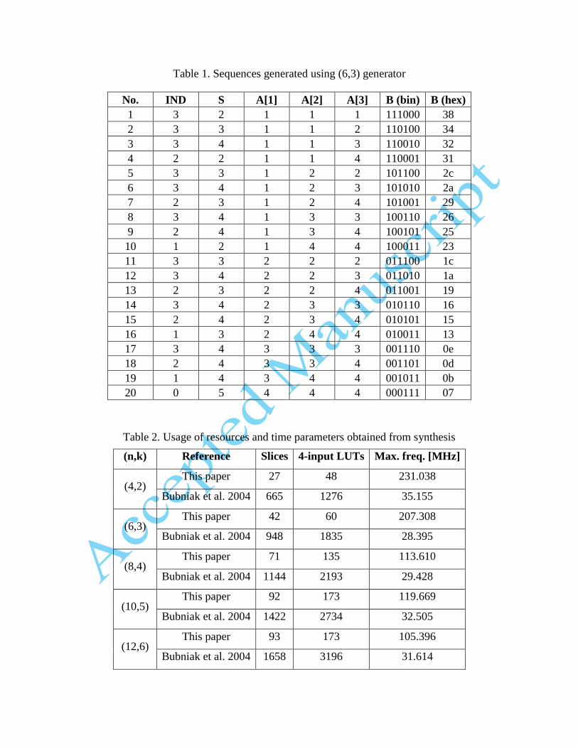
Table 1. Sequences generated using (6,3) generator
No. IND S A[1] A[2] A[3] B (bin) B (hex)
1 3 2 1 1 1 111000 38
2 3 3 1 1 2 110100 34
3 3 4 1 1 3 110010 32
4 2 2 1 1 4 110001 31
5 3 3 1 2 2 101100 2c
6 3 4 1 2 3 101010 2a
7 2 3 1 2 4 101001 29
8 3 4 1 3 3 100110 26
9 2 4 1 3 4 100101 25
10 1 2 1 4 4 100011 23
11 3 3 2 2 2 011100 1c
12 3 4 2 2 3 011010 1a
13 2 3 2 2 4 011001 19
14 3 4 2 3 3 010110 16
15 2 4 2 3 4 010101 15
16 1 3 2 4 4 010011 13
17 3 4 3 3 3 001110 0e
18 2 4 3 3 4 001101 0d
19 1 4 3 4 4 001011 0b
20 0 5 4 4 4 000111 07
Table 2. Usage of resources and time parameters obtained from synthesis
(n,k) Reference Slices 4-input LUTs Max. freq. [MHz]
(4,2) This paper 27 48 231.038
Bubniak et al. 2004 665 1276 35.155
(6,3) This paper 42 60 207.308
Bubniak et al. 2004 948 1835 28.395
(8,4) This paper 71 135 113.610
Bubniak et al. 2004 1144 2193 29.428
(10,5) This paper 92 173 119.669
Bubniak et al. 2004 1422 2734 32.505
(12,6) This paper 93 173 105.396
Bubniak et al. 2004 1658 3196 31.614
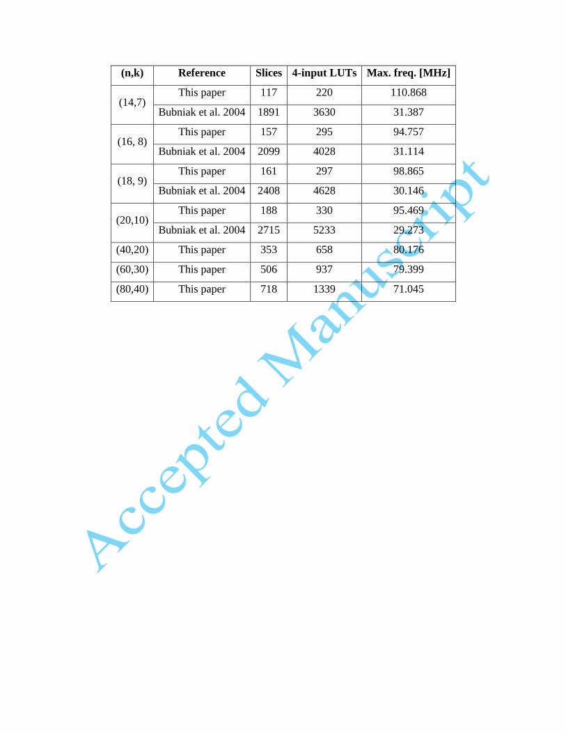
(n,k) Reference Slices 4-input LUTs Max. freq. [MHz]
(14,7) This paper 117 220 110.868
Bubniak et al. 2004 1891 3630 31.387
(16, 8) This paper 157 295 94.757
Bubniak et al. 2004 2099 4028 31.114
(18, 9) This paper 161 297 98.865
Bubniak et al. 2004 2408 4628 30.146
(20,10) This paper 188 330 95.469
Bubniak et al. 2004 2715 5233 29.273
(40,20) This paper 353 658 80.176
(60,30) This paper 506 937 79.399
(80,40) This paper 718 1339 71.045


![TECHNICAL TRANSACTIONS CZASOPISMO TECHNICZNE...[Z39] Rachunek różniczkowy i całkowy (manuscript lithographic copied), Lwów 1881–2, 303 + 1 nlb. [Z40] Wykład geometryi analitycznej](https://static.fdocuments.pl/doc/165x107/611e67a6b5e104508f60c011/technical-transactions-czasopismo-techniczne-z39-rachunek-rniczkowy-i.jpg)