Abb Rtxh24
12
Page 1 Features Fai l-s afe se quence d isco nne cti ng of current, voltage and trip circuits when the test-plug handle is inserted • Lat chi ng fea tur e so tha t when the test- plu g handle is withdrawn the relay stabilizes in its reset position before the trip circuits are restored • Compl ete isolation of second ary instrument transformer circuits • Tri p-block plug which isolat es a trip circuit without interrupting other circuits, allows the trip output to be monitored, and also provides visual indication of an isolated trip circuit • Block- plug handle whic h disc onnect s all circuits routed through the test switch • Ammeter test -plu g wit h loca l auto mat ic shorting device in case of inadvertent opening of a CT circuit • Aux ili ary s tat ion power s upp ly ma de available for operating test equipment • Ext ension bases which facilitate measurement and adjustment of plug-in module circuits Application The COMBITEST system for testing of pro- tection relays is built up around the R TXP 8, RTXP 18 or RTXP 24 test swi tches. The test switch can also be used for other testing needs not directly associated with relays, such as for switchboards or voltmeters. The test switch may be used where testing would otherwise require disconnection of the instrument transformer’s secondary or control wiring. It may also be used to advantage in the testing of other complete relay systems, even when each individual relay has its own test switch. When the test-plug handle is inserted into the test switch, preparations for testing are auto- matically carried out in the proper sequence, i.e. blocking of tripping circuits, short-circuit- ing of CT’s, opening of voltage circuits, mak- ing relay terminals available for secondary injection. The test-plug handle may be connected to any type of test equipment or instrument. When a number of protection relays of the same type are tested, the test-plug handle need to be moved only from the test switch of one relay to the test switch of the other, without altering previously made connections. If different types of relays are to be tested, it is a simple matter to change the connections on the test- plug handle and the relay testing set. (xx04000325.jpg) T est System COMBITEST 1MRK 512 001-BEN Issued July 2004 Revision: B Data subject to change without notice
-
Upload
luis-miguel-diaz -
Category
Documents
-
view
215 -
download
0
Transcript of Abb Rtxh24
8/9/2019 Abb Rtxh24
http://slidepdf.com/reader/full/abb-rtxh24 1/12
Page 1
Features Fail-safe sequence disconnecting ofcurrent, voltage and trip circuits when the
test-plug handle is inserted
• Latching feature so that when the test-plug
handle is withdrawn the relay stabilizes in
its reset position before the trip circuits arerestored
• Complete isolation of secondary instrument
transformer circuits
• Trip-block plug which isolates a trip circuitwithout interrupting other circuits, allowsthe trip output to be monitored, and also
provides visual indication of an isolated tripcircuit
• Block-plug handle which disconnects allcircuits routed through the test switch
• Ammeter test-plug with local automaticshorting device in case of inadvertent
opening of a CT circuit
• Auxiliary station power supply madeavailable for operating test equipment
• Extension bases which facilitatemeasurement and adjustment of plug-in
module circuits
Application The COMBITEST system for testing of pro-tection relays is built up around the RTXP 8,
RTXP 18 or RTXP 24 test switches. The testswitch can also be used for other testingneeds not directly associated with relays,such as for switchboards or voltmeters.
The test switch may be used where testingwould otherwise require disconnection of theinstrument transformer’s secondary or controlwiring. It may also be used to advantage inthe testing of other complete relay systems,even when each individual relay has its owntest switch.
When the test-plug handle is inserted into the
test switch, preparations for testing are auto-matically carried out in the proper sequence,
i.e. blocking of tripping circuits, short-circuit-ing of CT’s, opening of voltage circuits, mak-
ing relay terminals available for secondaryinjection.
The test-plug handle may be connected to anytype of test equipment or instrument. When anumber of protection relays of the same typeare tested, the test-plug handle need to bemoved only from the test switch of one relayto the test switch of the other, without alteringpreviously made connections. If differenttypes of relays are to be tested, it is a simplematter to change the connections on the test-plug handle and the relay testing set.
(xx04000325.jpg)
Test System COMBITEST
1MRK 512 001-BEN
Issued July 2004Revision: B
Data subject to change without notice
8/9/2019 Abb Rtxh24
http://slidepdf.com/reader/full/abb-rtxh24 2/12
Test System COMBITEST1MRK 512 001-BEN
Page 2
Design The COMBITEST system comprises of thetest switch RTXP, the test-plug handle RTXHand the block-plug handle, RTXF. These are
designed in three different versions equippedwith either 8, 18 or 24 contacts.
Together with the test leads, the trip-blockplug RTXB, and an ammeter test-plugRTXM, the COMBITEST forms a completesystem for the fast and safe testing of protec-tion relays.
Test switchThe test switch, RTXP, is built up in a lightbeige housing containing a number of contactunits. The contact units are of two basictypes. One type is for trip circuits and
designed to open first and close last when thetest handle is inserted respectively removed.The other type is used for all other circuitfunctions, current, voltage and auxiliarypower. If the housing is not fully equippedwith contact units, unused space is occupiedby dummies of the same shape as the contactunits.
Each test circuit contains two similar, adja-cent contact units with the exception of theunits for dc supply voltage. An additionalshorting bar, which is mounted within por-
tions of the test switch, provides the neces-sary short-circuiting of the currenttransformer circuits when the test-plug handleis inserted. All contact units have space for amarking symbol on the front, indicating thesignificance of it.
The connections are done directly to 20 ACOMBIFLEX terminals at the rear of the testswitch. The signalling contact on RTXP 24has 10 A terminals.
The test switches are available with differentcontact arrangements (see ordering table).
The contact units have guiding slots fittingthe guides of the test pins, to prevent incor-rect insertion of the test-plug handle. Theavailable contact arrangements and markingsymbols are shown in the ordering table.
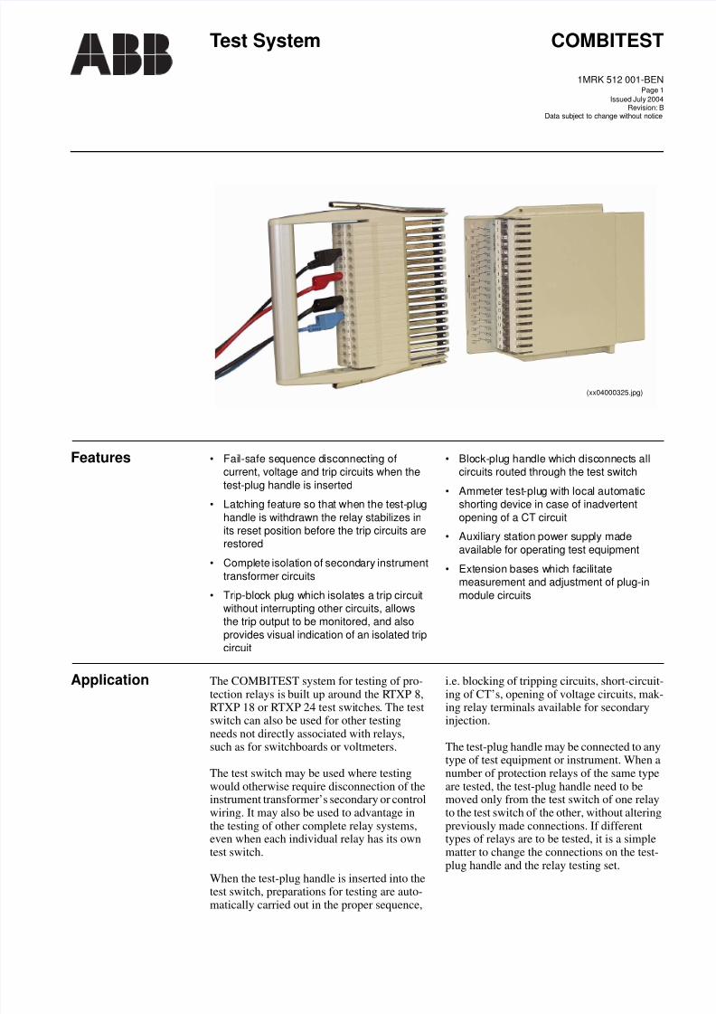
Test switch RTXP 8The test switch RTXP 8 contains eight con-tacts. It occupies one seat in the COMBI-FLEX system with dimensions 2U and 6C.An adapter is used for mounting of the RTXP8 in a 4U rack assembly. This allows one RX1 terminal base to be mounted under theRTXP 8 (see Fig. 1).
Fig. 1 The assembly of RTXP 8 and terminalbase RX 1 with the 4U adapter.
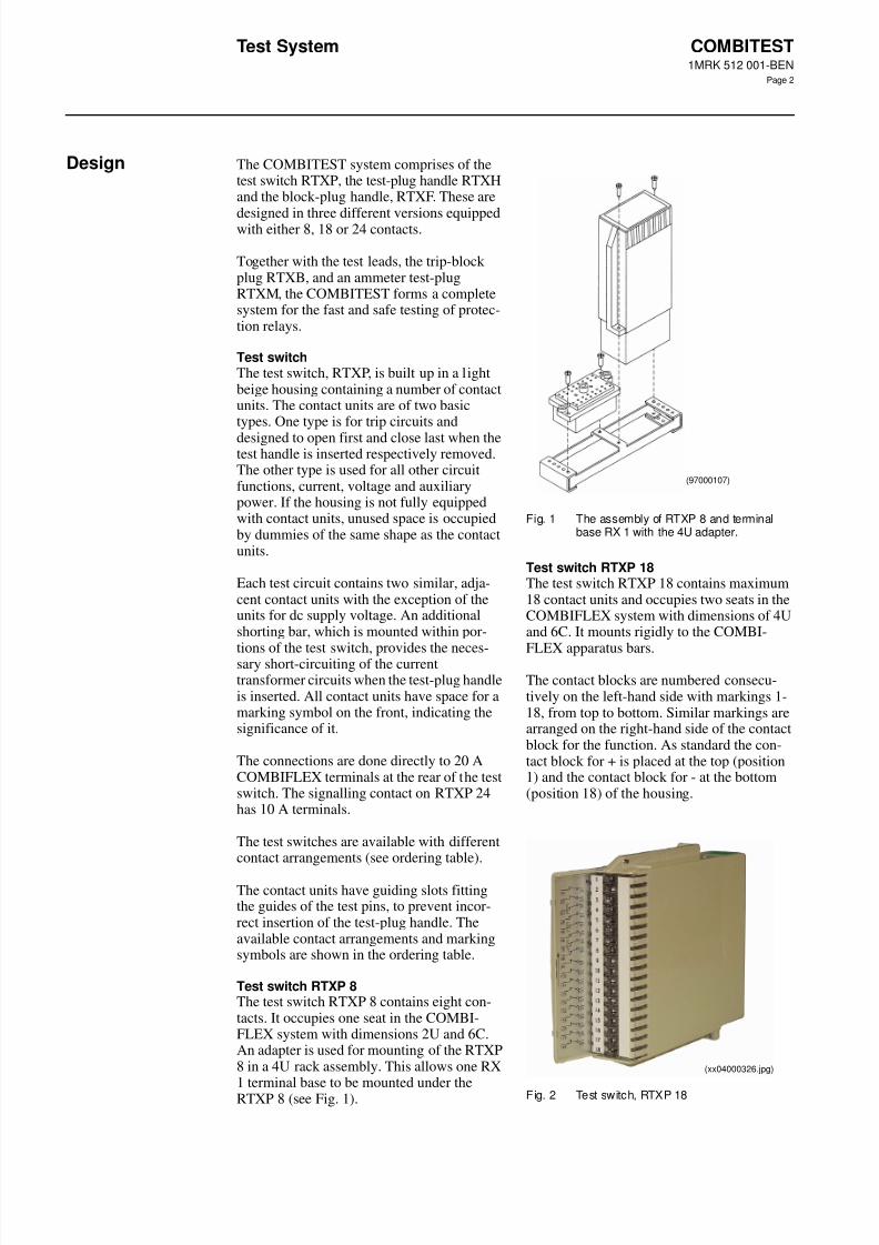
Test switch RTXP 18The test switch RTXP 18 contains maximum18 contact units and occupies two seats in theCOMBIFLEX system with dimensions of 4Uand 6C. It mounts rigidly to the COMBI-
FLEX apparatus bars.
The contact blocks are numbered consecu-tively on the left-hand side with markings 1-18, from top to bottom. Similar markings arearranged on the right-hand side of the contactblock for the function. As standard the con-tact block for + is placed at the top (position1) and the contact block for - at the bottom(position 18) of the housing.
Fig. 2 Test switch, RTXP 18
(97000107)
(xx04000326.jpg)
8/9/2019 Abb Rtxh24
http://slidepdf.com/reader/full/abb-rtxh24 3/12
Test System COMBITEST1MRK 512 001-BEN
Page 3
The front of the test switch is a door with twoface labels having space for the test deviceand the protection relay data. Space is also
provided for text specified by the customer.On the back of the door there is a label show-ing the type and location of the contacts andbypassing bars used in the test switch.
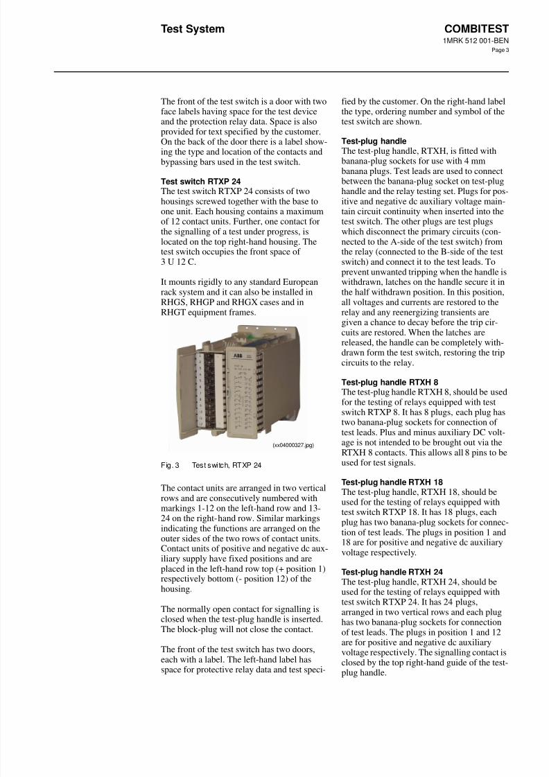
Test switch RTXP 24The test switch RTXP 24 consists of twohousings screwed together with the base toone unit. Each housing contains a maximumof 12 contact units. Further, one contact forthe signalling of a test under progress, islocated on the top right-hand housing. Thetest switch occupies the front space of3 U 12 C.
It mounts rigidly to any standard Europeanrack system and it can also be installed inRHGS, RHGP and RHGX cases and inRHGT equipment frames.
Fig. 3 Test switch, RTXP 24
The contact units are arranged in two verticalrows and are consecutively numbered withmarkings 1-12 on the left-hand row and 13-24 on the right-hand row. Similar markingsindicating the functions are arranged on theouter sides of the two rows of contact units.Contact units of positive and negative dc aux-iliary supply have fixed positions and areplaced in the left-hand row top (+ position 1)respectively bottom (- position 12) of thehousing.
The normally open contact for signalling isclosed when the test-plug handle is inserted.The block-plug will not close the contact.
The front of the test switch has two doors,each with a label. The left-hand label hasspace for protective relay data and test speci-
fied by the customer. On the right-hand labelthe type, ordering number and symbol of thetest switch are shown.
Test-plug handleThe test-plug handle, RTXH, is fitted withbanana-plug sockets for use with 4 mmbanana plugs. Test leads are used to connectbetween the banana-plug socket on test-plughandle and the relay testing set. Plugs for pos-itive and negative dc auxiliary voltage main-tain circuit continuity when inserted into thetest switch. The other plugs are test plugswhich disconnect the primary circuits (con-nected to the A-side of the test switch) fromthe relay (connected to the B-side of the testswitch) and connect it to the test leads. To
prevent unwanted tripping when the handle iswithdrawn, latches on the handle secure it inthe half withdrawn position. In this position,all voltages and currents are restored to therelay and any reenergizing transients aregiven a chance to decay before the trip cir-cuits are restored. When the latches arereleased, the handle can be completely with-drawn form the test switch, restoring the tripcircuits to the relay.
Test-plug handle RTXH 8The test-plug handle RTXH 8, should be usedfor the testing of relays equipped with testswitch RTXP 8. It has 8 plugs, each plug hastwo banana-plug sockets for connection oftest leads. Plus and minus auxiliary DC volt-age is not intended to be brought out via theRTXH 8 contacts. This allows all 8 pins to beused for test signals.
Test-plug handle RTXH 18The test-plug handle, RTXH 18, should beused for the testing of relays equipped withtest switch RTXP 18. It has 18 plugs, eachplug has two banana-plug sockets for connec-tion of test leads. The plugs in position 1 and
18 are for positive and negative dc auxiliaryvoltage respectively.
Test-plug handle RTXH 24The test-plug handle, RTXH 24, should beused for the testing of relays equipped withtest switch RTXP 24. It has 24 plugs,arranged in two vertical rows and each plughas two banana-plug sockets for connectionof test leads. The plugs in position 1 and 12are for positive and negative dc auxiliaryvoltage respectively. The signalling contact isclosed by the top right-hand guide of the test-plug handle.
(xx04000327.jpg)
8/9/2019 Abb Rtxh24
http://slidepdf.com/reader/full/abb-rtxh24 4/12
Test System COMBITEST1MRK 512 001-BEN
Page 4
Design (cont’d)Design (cont’d)
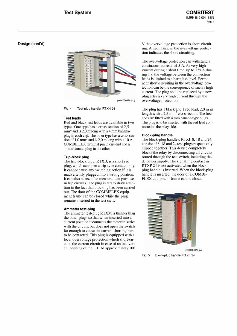
Fig. 4 Test-plug handle, RTXH 24
Test leadsRed and black test leads are available in twotypes. One type has a cross section of 2,5mm2 and is 2,0 m long with a 4 mm banana-plug in each end. The other type has a cross sec-tion of 1,0 mm2 and is 2,0 m long with a 10 ACOMBIFLEX terminal pin in one end and a4 mm banana-plug in the other.
Trip-block plugThe trip-block plug, RTXB, is a short redplug, which can open a trip-type contact only.It cannot cause any switching action if it isinadvertently plugged into a wrong position.It can also be used for measurement purposesin trip circuits. The plug is red to draw atten-tion to the fact that blocking has been carriedout. The door of the COMBIFLEX equip-ment frame can be closed while the plugremains inserted in the test switch.
Ammeter test-plugThe ammeter test-plug RTXM is thinner thanthe other plugs so that when inserted into acurrent position it connects the meter in serieswith the circuit, but does not open the switchfar enough to cause the current shorting bars
to be contacted. This plug is equipped with alocal overvoltage protection which short-cir-cuits the current circuit in case of an inadvert-ent opening of the CT. At approximately 100
V the overvoltage protection is short-circuit-ing. A neon lamp in the overvoltage protec-tion indicates the short-circuiting.
The overvoltage protection can withstand acontinuous current of 5 A. At very highcurrent during a short time, up to 125 A dur-ing 1 s, the voltage between the connectionleads is limited to a harmless level. Perma-nent short-circuiting in the overvoltage pro-tection can be the consequence of such a highcurrent. The plug shall be replaced by a newplug after a very high current through theovervoltage protection.
The plug has 1 black and 1 red lead, 2,0 m inlength with a 2,5 mm2 cross-section. The free
ends are fitted with 4 mm banana-type plugs.The plug is to be inserted with the red lead con-nected to the relay side.
Block-plug handleThe block-plug handles, RTXF 8, 18 and 24,consist of 8, 18 and 24 test-plugs respectively,clipped together. This device completelyblocks the relay by disconnecting all circuitsrouted through the test switch, including thedc power supply. The signalling contact inRTXP 24 is not activated when the block-plug handle is inserted. When the block-plughandle is inserted, the door of a COMBI-FLEX equipment frame can be closed.
Fig. 5 Block-plug handle, RTXF 24
(xx04000328.jpg)
(xx04000329.jpg)
8/9/2019 Abb Rtxh24
http://slidepdf.com/reader/full/abb-rtxh24 5/12
Test System COMBITEST1MRK 512 001-BEN
Page 5
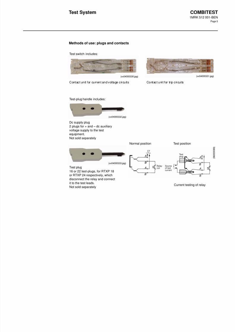
Methods of use: plugs and contacts
Test switch includes:
Contact unit for current and voltage circuits Contact unit for trip circuits
(xx04000330.jpg) (832008)(xx04000331.jpg)
Test-plug handle includes:
Dc supply plug
2 plugs for + and – dc auxiliary
voltage supply to the test
equipment.
Not sold separately
Test plug
16 or 22 test-plugs, for RTXP 18
or RTXP 24 respectively, whichdisconnect the relay and connect
it to the test leads.
Not sold separately
Normal position Test position
Current testing of relay
(xx04000332.jpg)
(xx04000333.jpg)
( 9 6 0 0 0 0 8 9 )
8/9/2019 Abb Rtxh24
http://slidepdf.com/reader/full/abb-rtxh24 6/12
Test System COMBITEST1MRK 512 001-BEN
Page 6
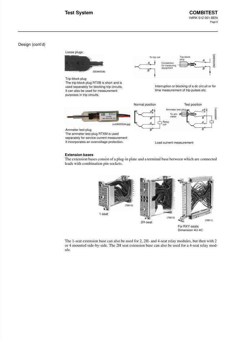
Design (cont’d)
Extension basesThe extension bases consist of a plug-in plate and a terminal base between which are connectedleads with combination pin-sockets.
The 1-seat extension base can also be used for 2, 2H- and 4-seat relay modules, but then with 2or 4 mounted side-by-side. The 2H seat extension base can also be used for a 4-seat relay mod-ule.
Loose plugs:
Trip-block plug
The trip-block plug RTXB is short and is
used separately for blocking trip circuits.
It can also be used for measurement
purposes in trip circuits.
Interruption or blocking of a dc circuit or for
time measurement of trip pulses etc.
Normal position Test position
Ammeter test-plug
The ammeter test-plug RTXM is used
separately for service current measurement
It incorporates an overvoltage protection. Load current measurement
(SE840538)
( 9 6 0 0 0 0
8 9 0 )
(xx04000334.jpg)
(
9 6 0 0 0 0 9 1 )
(76813)
(76812)(76811)
1-seat
2H-seat
For RXY-seatsDimension 4U 4C
8/9/2019 Abb Rtxh24
http://slidepdf.com/reader/full/abb-rtxh24 7/12
Test System COMBITEST1MRK 512 001-BEN
Page 7
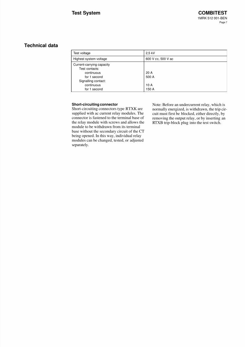
Technical data
Short-circuiting connectorShort-circuiting connectors type RTXK aresupplied with ac current relay modules. Theconnector is fastened to the terminal base of
the relay module with screws and allows themodule to be withdrawn from its terminalbase without the secondary circuit of the CTbeing opened. In this way, individual relaymodules can be changed, tested, or adjustedseparately.
Note: Before an undercurrent relay, which isnormally energized, is withdrawn, the trip cir-cuit must first be blocked, either directly, byremoving the output relay, or by inserting an
RTXB trip-block plug into the test switch.
Test voltage 2,5 kV
Highest system voltage 600 V dc, 500 V ac
Current-carrying capacity
Test contacts:
continuous
for 1 second
Signalling contact:
continuous
for 1 second
20 A
500 A
10 A
150 A
8/9/2019 Abb Rtxh24
http://slidepdf.com/reader/full/abb-rtxh24 8/12
Test System COMBITEST1MRK 512 001-BEN
Page 8
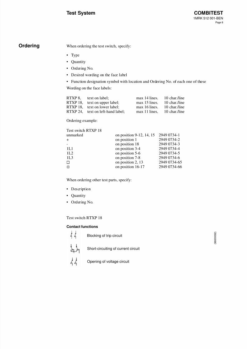
Ordering When ordering the test switch, specify:
• Type
• Quantity
• Ordering No.
• Desired wording on the face label
• Function designation symbol with location and Ordering No. of each one of these
Wording on the face labels:
Ordering example:
When ordering other test parts, specify:
• Description
• Quantity
• Ordering No.
Test switch RTXP 18
Contact functions
RTXP 8,RTXP 18,RTXP 18,RTXP 24,
text on label;text on upper label;text on lower label;text on left-hand label;
max 14 lines,max 15 lines,max 16 lines,max 11 lines,
10 char./line10 char./line10 char./line10 char./line
Test switch RTXP 18unmarked+-1L11L21L3
on position 9-12, 14, 15on position 1on position 18on position 3-4on position 5-6on position 7-8on position 2, 13on position 16-17
2949 0734-12949 0734-22949 0734-32949 0734-42949 0734-52949 0734-62949 0734-652949 0734-66
Blocking of trip circuit
Short-circuiting of current circuit
Opening of voltage circuit
( 9 6 0 0 0 0 9 2 )
8/9/2019 Abb Rtxh24
http://slidepdf.com/reader/full/abb-rtxh24 9/12
Test System COMBITEST1MRK 512 001-BEN
Page 9
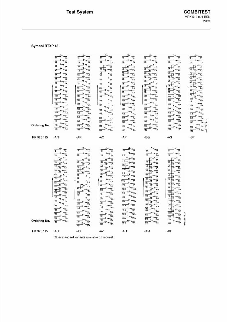
Symbol RTXP 18
Ordering No.
RK 926 115 -AN -AR -AC -AP -BG -AS -BF
Ordering No.
RK 926 115 -AD -AX -AV -AH -AM -BH
Other standard variants available on request
( r k 9 2 6 1 1 5 - x y )
( r k 9 2 6 1 1 5 - x x )
8/9/2019 Abb Rtxh24
http://slidepdf.com/reader/full/abb-rtxh24 10/12
Test System COMBITEST1MRK 512 001-BEN
Page 10
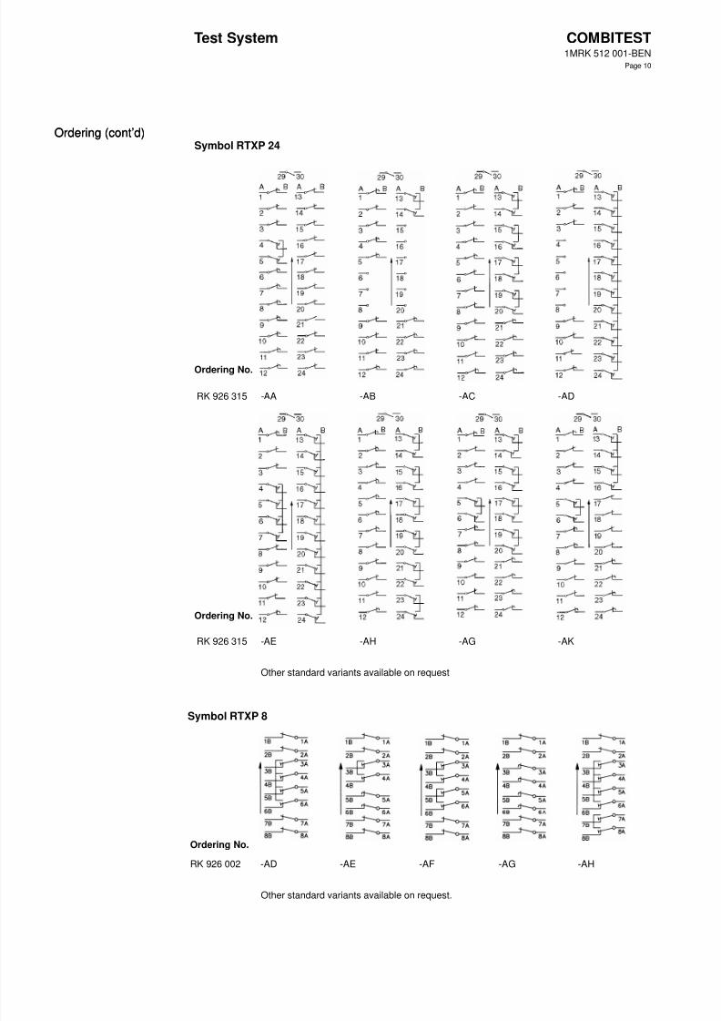
Ordering (cont’d)Ordering (cont’d)Symbol RTXP 24
Ordering No.
RK 926 315 -AA -AB -AC -AD
Ordering No.
RK 926 315 -AE -AH -AG -AK
Other standard variants available on request
Symbol RTXP 8
Ordering No.
RK 926 002 -AD -AE -AF -AG -AH
Other standard variants available on request.
8/9/2019 Abb Rtxh24
http://slidepdf.com/reader/full/abb-rtxh24 11/12
Test System COMBITEST1MRK 512 001-BEN
Page 11
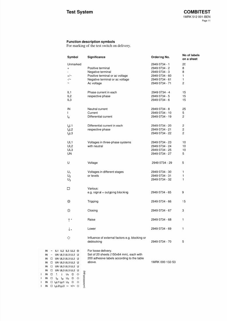
Function description symbolsFor marking of the test switch on delivery.
Symbol Significance Ordering No. No of labelson a sheet
Unmarked
+
-
+/~
-/ ~~
Positive terminal
Negative terminal
Positive terminal or ac voltage
Negative terminal or ac voltage
Ac voltage
2949 0734 - 1
2949 0734 - 2
2949 0734 - 3
2949 0734 - 60
2949 0734 - 61
2949 0734 - 71
20
8
8
1
1
2
IL1
IL2
IL3
Phase current in each
respective phase
2949 0734 - 4
2949 0734 - 5
2949 0734 - 6
15
15
15
IN
IId
Neutral current
CurrentDifferential current
2949 0734 - 8
2949 0734 - 102949 0734 - 19
25
52
IdL1
IdL2
IdL3
Differential current in each
respective phase
2949 0734 - 20
2949 0734 - 21
2949 0734 - 22
2
2
2
UL1
UL2
UL3
UN
Voltages in three-phase systems
with neutral
2949 0734 - 23
2949 0734 - 24
2949 0734 - 25
2949 0734 - 27
10
10
10
5
U Voltage 2949 0734 - 29 5
U1
U2
U3
Voltages in different stages
or levels
2949 0734 - 30
2949 0734 - 31
2949 0734 - 32
1
1
1
Various:
e.g. signal + outgoing blocking 2949 0734 - 65 9
Tripping 2949 0734 - 66 15
Closing 2949 0734 - 67 3
Raise 2949 0734 - 68 1
Lower 2949 0734 - 69 1
Influence of external factors e.g. blocking or
deblocking 2949 0734 - 70 5
For loose delivery.
Set of 20 sheets (150x64 mm), each with
200 adhesive labels according to the table
above. 1MRK 000 132-53
→•
→•
( x x 0 4 0 0
0 3 3 5 .
j p g )
8/9/2019 Abb Rtxh24
http://slidepdf.com/reader/full/abb-rtxh24 12/12
Test System COMBITEST1MRK 512 001-BEN
Page 12
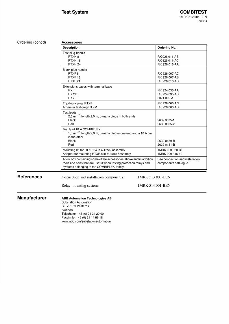
Ordering (cont’d) Accessories
References Connection and installation components 1MRK 513 003-BEN
Relay mounting systems 1MRK 514 001-BEN
Manufacturer ABB Automation Technologies AB
Substation Automation
SE-721 59 Västerås
Sweden
Telephone: +46 (0) 21 34 20 00
Facsimile: +46 (0) 21 14 69 18
www.abb.com/substationautomation
Description Ordering No.
Test-plug handle
RTXH 8RTXH 18
RTXH 24
RK 926 011-AERK 926 011-AC
RK 926 016-AA
Block-plug handle
RTXF 8
RTXF 18
RTXF 24
RK 926 007-AC
RK 926 007-AB
RK 926 016-AB
Extensions bases with terminal base
RX 1
RX 2H
RXY
RK 924 035-AA
RK 924 035-AB
5371 069-A
Trip-block plug, RTXB
Ammeter test-plug RTXM
RK 926 005-AC
RK 926 006-AB
Test leads2,5 mm2, length 2,0 m, banana plugs in both ends
Black
Red
2639 0605-1
2639 0605-2
Test lead 10 A COMBIFLEX
1,0 mm2, length 2,0 m, banana plug in one end and a 10 A pin
in the other
Black
Red
2639 0180-B
2639 0181-B
Mounting kit for RTXP 24 in 4U rack assembly
Adapter for mounting RTXP 8 in 4U rack assembly
1MRK 000 020-BT
1MRK 000 316-19
A tool box containing some of the accessories above and in addition
tools and parts that are useful when testing protection relays and
systems belonging to the COMBIFLEX family.
See connection and installation
components catalogue.