1.4 Saia PCD1 - automatyka przemysłowa Warszawa · The Saia PCD1.M2xxx series is a compact...
12
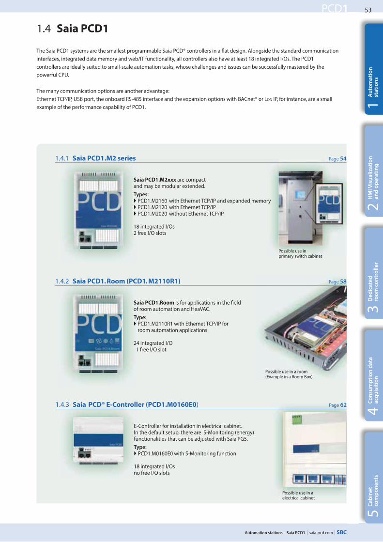
53 saia-pcd.com PCD1 Automation stations – Saia PCD1 5 4 3 2 1 Cabinet components Dedicated room controller HMI Visualization and operating Automation stations Consumption data acquisition 1.4.3 Saia PCD® E-Controller (PCD1.M0160E0) Page 62 E-Controller for installation in electrical cabinet. In the default setup, there are S-Monitoring (energy) functionalities that can be adjusted with Saia PG5. Type: ` PCD1.M0160E0 with S-Monitoring function 18 integrated I/Os no free I/O slots The Saia PCD1 systems are the smallest programmable Saia PCD® controllers in a flat design. Alongside the standard communication interfaces, integrated data memory and web/IT functionality, all controllers also have at least 18 integrated I/Os. The PCD1 controllers are ideally suited to small-scale automation tasks, whose challenges and issues can be successfully mastered by the powerful CPU. The many communication options are another advantage: Ethernet TCP/IP, USB port, the onboard RS-485 interface and the expansion options with BACnet® or LON IP, for instance, are a small example of the performance capability of PCD1. 1.4 Saia PCD1 1.4.2 Saia PCD1.Room (PCD1. M2110R1) Page 58 Saia PCD1.Room is for applications in the field of room automation and HeaVAC. Type: ` PCD1.M2110R1 with Ethernet TCP/IP for room automation applications 24 integrated I/O 1 free I/O slot 1.4.1 Saia PCD1.M2 series Page 54 Saia PCD1.M2xxx are compact and may be modular extended. Types: ` PCD1.M2160 with Ethernet TCP/IP and expanded memory ` PCD1.M2120 with Ethernet TCP/IP ` PCD1.M2020 without Ethernet TCP/IP 18 integrated I/Os 2 free I/O slots Possible use in primary switch cabinet Possible use in a room (Example in a Room Box) Possible use in a electrical cabinet
Transcript of 1.4 Saia PCD1 - automatyka przemysłowa Warszawa · The Saia PCD1.M2xxx series is a compact...
53
saia-pcd.com
PCD1
Automation stations – Saia PCD1
54
32
1C
ab
ine
t
com
po
ne
nts
De
dic
ate
d
roo
m c
on
tro
lle
rH
MI V
isu
ali
zati
on
a
nd
op
era
tin
gA
uto
ma
tio
n
sta
tio
ns
Co
nsu
mp
tio
n d
ata
a
cqu
isit
ion
1.4.3 Saia PCD® E-Controller (PCD1.M0160E0) Page 62
E-Controller for installation in electrical cabinet. In the default setup, there are S-Monitoring (energy) functionalities that can be adjusted with Saia PG5.
Type: PCD1.M0160E0 with S-Monitoring function
18 integrated I/Osno free I/O slots
The Saia PCD1 systems are the smallest programmable Saia PCD® controllers in a Nat design. Alongside the standard communication
interfaces, integrated data memory and web/IT functionality, all controllers also have at least 18 integrated I/Os. The PCD1
controllers are ideally suited to small-scale automation tasks, whose challenges and issues can be successfully mastered by the
powerful CPU.
The many communication options are another advantage:
Ethernet TCP/IP, USB port, the onboard RS-485 interface and the expansion options with BACnet® or LON IP, for instance, are a small
example of the performance capability of PCD1.
1.4 Saia PCD1
1.4.2 Saia PCD1.Room (PCD1. M2110R1) Page 58
Saia PCD1.Room is for applications in the Yeld of room automation and HeaVAC.
Type: PCD1.M2110R1 with Ethernet TCP/IP for room automation applications
24 integrated I/O 1 free I/O slot
1.4.1 Saia PCD1.M2 series Page 54
Saia PCD1.M2xxx are compact and may be modular extended.
Types: PCD1.M2160 with Ethernet TCP/IP and expanded memory PCD1.M2120 with Ethernet TCP/IP PCD1.M2020 without Ethernet TCP/IP
18 integrated I/Os2 free I/O slots
Possible use in primary switch cabinet
Possible use in a room (Example in a Room Box)
Possible use in a electrical cabinet
54
saia-pcd.com
PCD1
M1
Slot A
X2 X1 X0
X3
142 49
22
6
Automation stations – Saia PCD1
Types
PCD1.M2160 with Ethernet TCP/IP
and expanded memory
PCD1.M2120 with Ethernet TCP/IP
PCD1.M2020 without Ethernet TCP/IP
System characteristics
Up to 50 inputs / outputs
may be expanded locally with RIO PCD3.T66x or PCD3.T76x
Up to 8 communication interfaces
USB and Ethernet interface onboard
Large onboard memory for programs (up to 1 MByte)
and data (up to 128 MByte Qle system)
Automation Server for integration into Web/IT systems
SNMP
Automation Server integrated in
the base unit
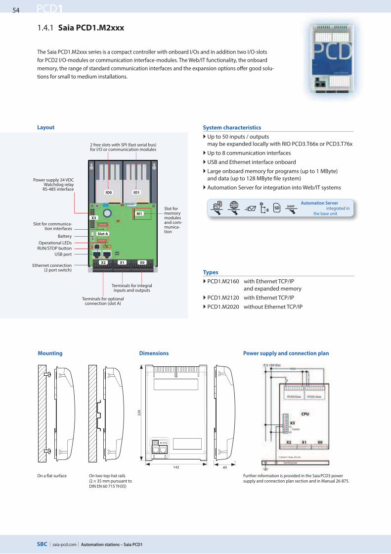
1.4.1 Saia PCD1.M2xxx
The Saia PCD1.M2xxx series is a compact controller with onboard I/Os and in addition two I/O-slots
for PCD2 I/O-modules or communication interface-modules. The Web/IT functionality, the onboard
memory, the range of standard communication interfaces and the expansion options oVer good solu-
tions for small to medium installations.
Layout
Slot for memory modules and com-munica-tion
Terminals for integral inputs and outputs
Terminals for optional connection (slot A)
2 free slots with SPI (fast serial bus) for I/O or communication modules
Power supply 24 VDCWatchdog relay
RS-485 interface
Ethernet connection(2 port switch)
USB port
Operational LEDs
Slot for communica-tion interfaces
Battery
RUN/STOP button
Mounting Dimensions Power supply and connection plan
Further information is provided in the Saia PCD3 power supply and connection plan section and in Manual 26-875.
On a Zat surface On two top-hat rails (2 × 35 mm pursuant to DIN EN 60 715 TH35)
Supply
Earthing bar
1.5mm2 / max. 25 cm
IO0 IO1
55
saia-pcd.com
PCD1
Automation stations – Saia PCD1
54
32
1C
ab
ine
t
com
po
ne
nts
De
dic
ate
d
roo
m c
on
tro
lle
rH
MI V
isu
ali
zati
on
a
nd
op
era
tin
gA
uto
ma
tio
n
sta
tio
ns
Co
nsu
mp
tio
n d
ata
a
cqu
isit
ion
Retaining catch Bus connector
I/O 0 I/O 1
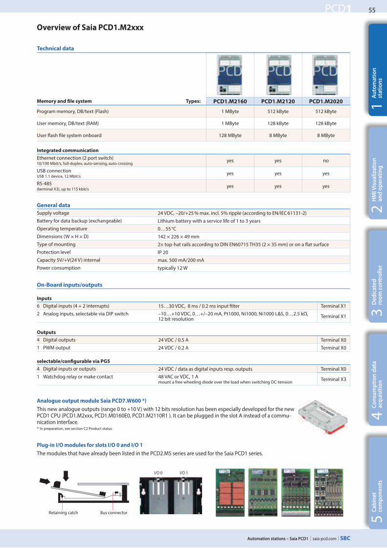
Memory and #le system Types: PCD1.M2160 PCD1.M2120 PCD1.M2020
Program memory, DB/text (Flash) 1 MByte 512 kByte 512 kByte
User memory, DB/text (RAM) 1 MByte 128 kByte 128 kByte
User Kash Lle system onboard 128 MByte 8 MByte 8 MByte
Integrated communication
Ethernet connection (2 port switch) 10/100 Mbit/s, full-duplex, auto-sensing, auto-crossing
yes yes no
USB connection USB 1.1 device, 12 Mbit/s
yes yes yes
RS-485 (terminal X3), up to 115 kbit/s
yes yes yes
Overview of Saia PCD1.M2xxx
On-Board inputs/outputs
Inputs
6 Digital inputs (4 + 2 interrupts) 15…30 VDC, 8 ms / 0.2 ms input Llter Terminal X1
2 Analog inputs, selectable via DIP switch –10…+10 VDC, 0…+/–20 mA, Pt1000, Ni1000, Ni1000 L&S, 0…2.5 kΩ, 12 bit resolution
Terminal X1
Outputs
4 Digital outputs 24 VDC / 0.5 A Terminal X0
1 PWM output 24 VDC / 0.2 A Terminal X0
selectable/con#gurable via PG5
4 Digital inputs or outputs 24 VDC / data as digital inputs resp. outputs Terminal X0
1 Watchdog relay or make contact 48 VAC or VDC, 1 A mount a free wheeling diode over the load when switching DC-tension
Terminal X3
General data
Supply voltage 24 VDC, –20/+25 % max. incl. 5% ripple (according to EN/IEC 61131-2)
Battery for data backup (exchangeable) Lithium battery with a service life of 1 to 3 years
Operating temperature 0…55 °C
Dimensions (W × H × D) 142 × 226 × 49 mm
Type of mounting 2× top-hat rails according to DIN EN60715 TH35 (2 × 35 mm) or on a Kat surface
Protection level IP 20
Capacity 5V/+V(24 V) internal max. 500 mA/200 mA
Power consumption typically 12 W
Plug-in I/O modules for slots I/O 0 and I/O 1
The modules that have already been listed in the PCD2.M5 series are used for the Saia PCD1 series.
Technical data
Analogue output module Saia PCD7.W600 *)
This new analogue outputs (range 0 to +10 V) with 12 bits resolution has been especially developed for the new PCD1 CPU (PCD1.M2xxx, PCD1.M0160E0, PCD1.M2110R1 ). It can be plugged in the slot A instead of a commu-nication interface.*) In preparation, see section C2 Product status
56
saia-pcd.com
PCD1
M1
Slot A
X2 X1 X0
X3
PCD7.R55xM04
PCD7.R610
Automation stations – Saia PCD1
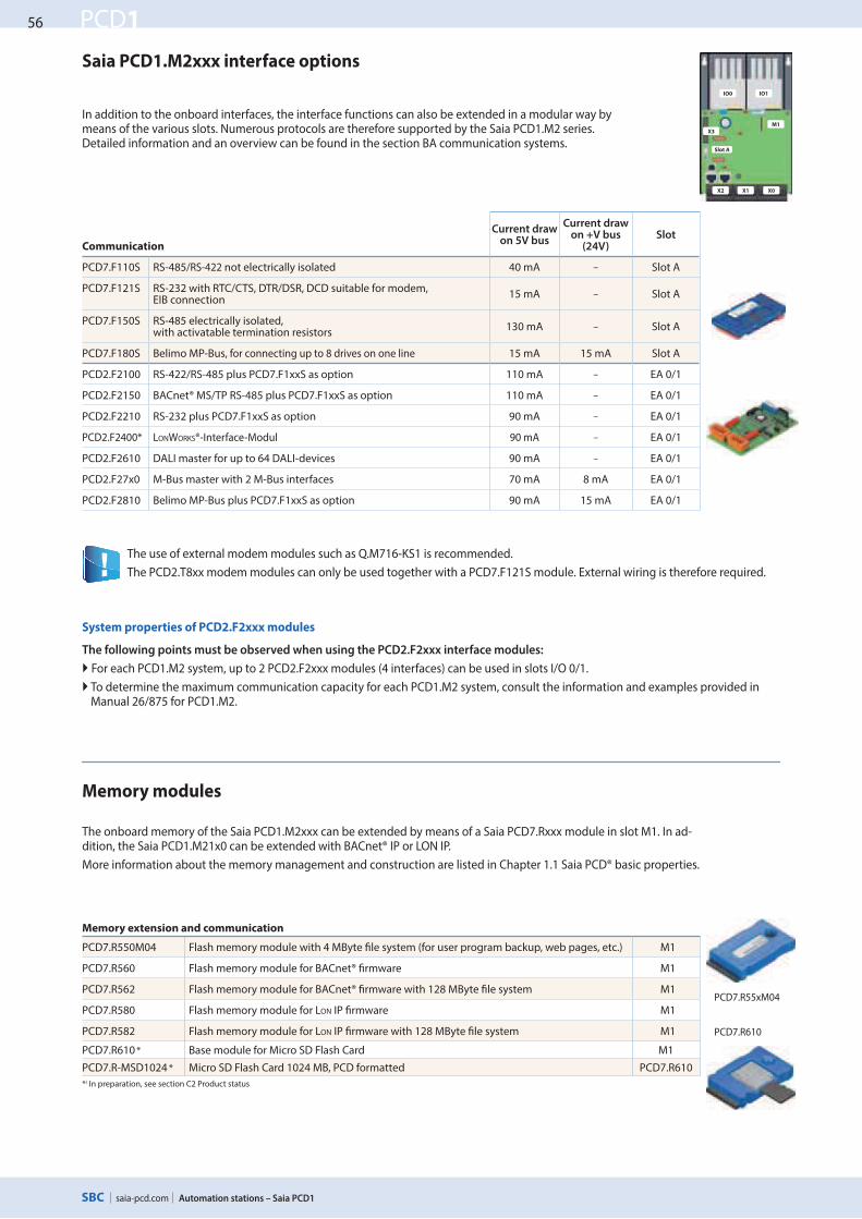
Communication
Current draw on 5V bus
Current draw on +V bus
(24V)Slot
PCD7.F110S RS-485/RS-422 not electrically isolated 40 mA – Slot A
PCD7.F121S RS-232 with RTC/CTS, DTR/DSR, DCD suitable for modem, EIB connection
15 mA – Slot A
PCD7.F150S RS-485 electrically isolated, with activatable termination resistors
130 mA – Slot A
PCD7.F180S Belimo MP-Bus, for connecting up to 8 drives on one line 15 mA 15 mA Slot A
PCD2.F2100 RS-422/RS-485 plus PCD7.F1xxS as option 110 mA – EA 0/1
PCD2.F2150 BACnet® MS/TP RS-485 plus PCD7.F1xxS as option 110 mA – EA 0/1
PCD2.F2210 RS-232 plus PCD7.F1xxS as option 90 mA – EA 0/1
PCD2.F2400* LONWORKS®-Interface-Modul 90 mA – EA 0/1
PCD2.F2610 DALI master for up to 64 DALI-devices 90 mA – EA 0/1
PCD2.F27x0 M-Bus master with 2 M-Bus interfaces 70 mA 8 mA EA 0/1
PCD2.F2810 Belimo MP-Bus plus PCD7.F1xxS as option 90 mA 15 mA EA 0/1
In addition to the onboard interfaces, the interface functions can also be extended in a modular way by means of the various slots. Numerous protocols are therefore supported by the Saia PCD1.M2 series. Detailed information and an overview can be found in the section BA communication systems.
Saia PCD1.M2xxx interface options
System properties of PCD2.F2xxx modules
The following points must be observed when using the PCD2.F2xxx interface modules:
For each PCD1.M2 system, up to 2 PCD2.F2xxx modules (4 interfaces) can be used in slots I/O 0/1.
To determine the maximum communication capacity for each PCD1.M2 system, consult the information and examples provided in Manual 26/875 for PCD1.M2.
Memory extension and communication
PCD7.R550M04 Flash memory module with 4 MByte Xle system (for user program backup, web pages, etc.) M1
PCD7.R560 Flash memory module for BACnet® Xrmware M1
PCD7.R562 Flash memory module for BACnet® Xrmware with 128 MByte Xle system M1
PCD7.R580 Flash memory module for LON IP Xrmware M1
PCD7.R582 Flash memory module for LON IP Xrmware with 128 MByte Xle system M1
PCD7.R610 * Base module for Micro SD Flash Card M1
PCD7.R-MSD1024 * Micro SD Flash Card 1024 MB, PCD formatted PCD7.R610
*) In preparation, see section C2 Product status
The onboard memory of the Saia PCD1.M2xxx can be extended by means of a Saia PCD7.Rxxx module in slot M1. In ad-dition, the Saia PCD1.M21x0 can be extended with BACnet® IP or LON IP.
More information about the memory management and construction are listed in Chapter 1.1 Saia PCD® basic properties.
The use of external modem modules such as Q.M716-KS1 is recommended.
The PCD2.T8xx modem modules can only be used together with a PCD7.F121S module. External wiring is therefore required.
Memory modules
IO0 IO1
57
saia-pcd.com
PCD1
Automation stations – Saia PCD1
54
32
1C
ab
ine
t
com
po
ne
nts
De
dic
ate
d
roo
m c
on
tro
lle
rH
MI V
isu
ali
zati
on
a
nd
op
era
tin
gA
uto
ma
tio
n
sta
tio
ns
Co
nsu
mp
tio
n d
ata
a
cqu
isit
ion
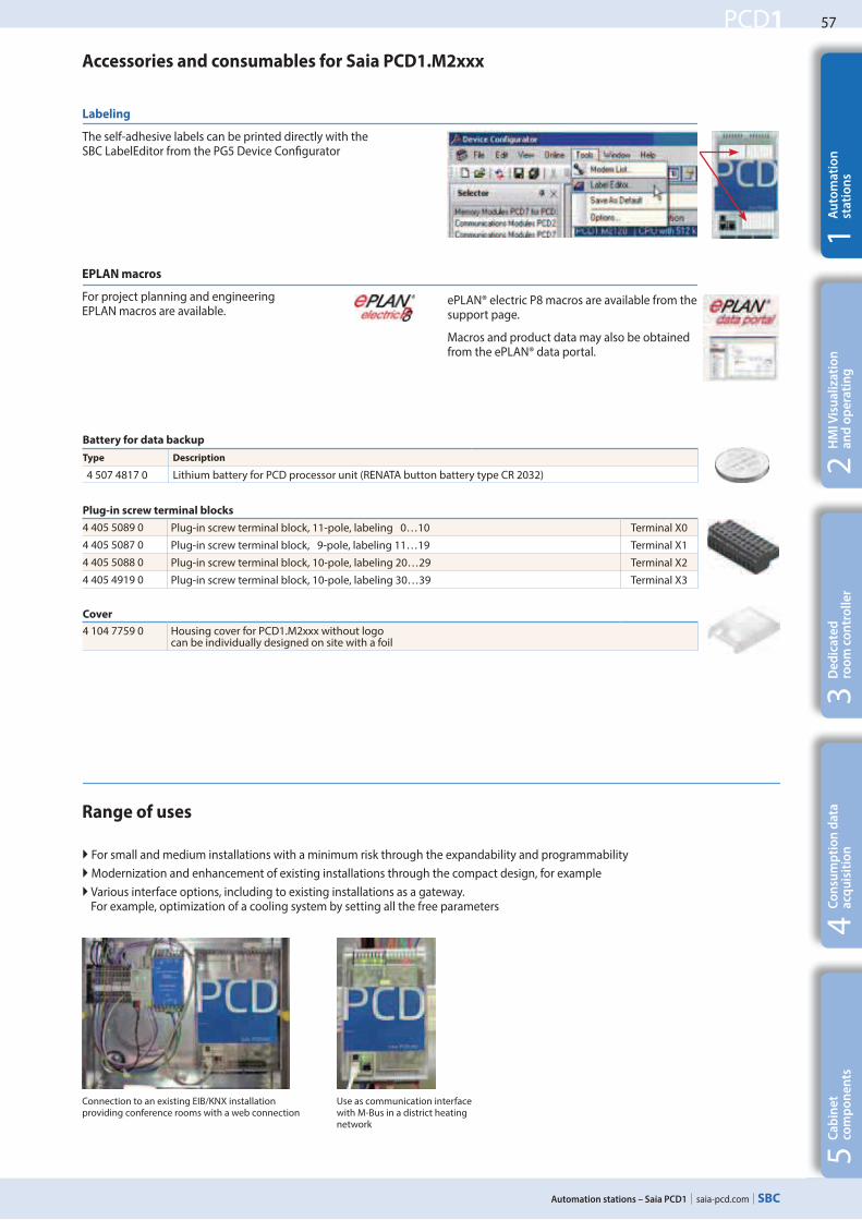
EPLAN macros
For project planning and engineering EPLAN macros are available.
Plug-in screw terminal blocks
4 405 5089 0 Plug-in screw terminal block, 11-pole, labeling 0…10 Terminal X0
4 405 5087 0 Plug-in screw terminal block, 9-pole, labeling 11…19 Terminal X1
4 405 5088 0 Plug-in screw terminal block, 10-pole, labeling 20…29 Terminal X2
4 405 4919 0 Plug-in screw terminal block, 10-pole, labeling 30…39 Terminal X3
Cover
4 104 7759 0 Housing cover for PCD1.M2xxx without logo can be individually designed on site with a foil
Battery for data backup
Type Description
4 507 4817 0 Lithium battery for PCD processor unit (RENATA button battery type CR 2032)
Accessories and consumables for Saia PCD1.M2xxx
For small and medium installations with a minimum risk through the expandability and programmability
Modernization and enhancement of existing installations through the compact design, for example
Various interface options, including to existing installations as a gateway. For example, optimization of a cooling system by setting all the free parameters
Labeling
The self-adhesive labels can be printed directly with the SBC LabelEditor from the PG5 Device ConZgurator
Use as communication interface with M-Bus in a district heating network
Range of uses
Connection to an existing EIB/KNX installation providing conference rooms with a web connection
ePLAN® electric P8 macros are available from the support page.
Macros and product data may also be obtained from the ePLAN® data portal.
58
saia-pcd.com
PCD1
142 49
22
6
Automation stations – Saia PCD1
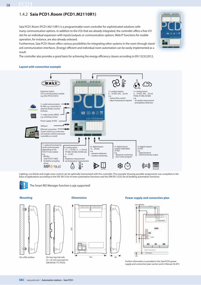
Layout with connection example
Lighting, sun blinds and single room control can be optimally harmonized with this controller. This example showing possible assignments was compiled on the basis of applications according to the VDI 3813 list of room automation functions and the DIN EN 15232 list of building automation functions.
The Smart RIO Manager function is not supported!
1.4.2 Saia PCD1.Room (PCD1.M2110R1)
Saia PCD1.Room (PCD1.M2110R1) is a programmable room controller for sophisticated solutions with
many communication options. In addition to the I/Os that are already integrated, the controller oTers a free I/O
slot for an individual expansion with inputs/outputs or communication options. Web/IT functions for mobile
operation, for instance, are also already onboard.
Furthermore, Saia PCD1.Room oTers various possibilities for integrating other systems in the room through stand-
ard communication interfaces. (Energy) eXcient and individual room automation can be easily implemented as a
result.
The controller also provides a good basis for achieving the energy eXciency classes according to EN 15232:2012.
1× serial communication RS-485: e.g. connection of external wireless receiver EnOcean
1× make contact 48VAC e.g. switching contact
Power supply 24 VDC
USB port
Ethernet connection (2 port switch) e.g. to the Inter-net (remote control via browser is possible as a result)
1× optional terminals for serial communication depending on the PCD7.F1xxS modulee.g. – MP-Bus
(with PCD7.F180S) for Belimo actuating drives.
2× analog inputs:– 10…+10 VDC, 0…+/-20 mA,
Pt1000, Ni1000, Ni1000 L&S, 0…2.5 kΩ
e.g. – brightness measurement– air temperature measurement
6× digital inputs:15…30 VDCe.g.– presence detection– window monitoring
4× digital inputs/outputs (selectable)24 VDCe.g.– dewpoint monitoring– time switch program
5× digital outputs:24 VDCe.g.– signal presence– switch/set binary output
2 × analog outputs:0…10 VDC, 0(4)…20 mAe.g.– volume eow control – adjust temperature setpoint
4 × analog inputs:0…10 VDC, 0(4)…20 mAPt500, Pt1000, Ni1000e.g.– air quality measurement – precipitation detection
Expansion optionI/O or communication module e.g. DALI (PCD2.F2610)
Mounting Dimensions Power supply and connection plan
Further information is provided in the Saia PCD3 power supply and connection plan section and in Manual 26-875.
On two top-hat rails (2 × 35 mm pursuant to DIN EN 60 715 TH35)
On a eat surface
Supply
Earthing bar
1.5mm2 / max. 25 cm

59
saia-pcd.com
PCD1
SNMP
Automation stations – Saia PCD1
54
32
1C
ab
ine
t
com
po
ne
nts
De
dic
ate
d
roo
m c
on
tro
lle
rH
MI V
isu
ali
zati
on
a
nd
op
era
tin
gA
uto
ma
tio
n
sta
tio
ns
Co
nsu
mp
tio
n d
ata
a
cqu
isit
ion
Overview of Saia PCD1.Room (PCD1.M2110R1)
General data
Supply voltage 24 VDC, –20/+25 % max. incl. 5% ripple (according to EN/IEC 61131-2)
Battery for data backup (exchangeable) Lithium battery with a service life of 1 to 3 years
Operating temperature 0…55 °C
Dimensions (W×H×D) 142 × 226 × 49 mm
Type of Mounting 2× top-hat rails according to DIN EN60715 TH35 (2 × 35 mm) or on a smooth surface
Protection type IP 20
Capacity 5V/+V(24V) internal max. 500 mA/200 mA
Power consumption typically 12 W
Automation Server Flash memory, Filesystem, FTP and Web-Server, E-Mail, SNMP
Only a PCD2.W525 module that is already supplied together with the controller in the default set up works in slot I/O 1.
If the module is removed, the controller stops.
Plug-in I/O modules for slot I/O 0
The modules that have already been listed in the PCD2.M5 series are used for the Saia PCD1 series.
Memory and #le system Type: PCD1.M2110R1
Program memory, DB/text (Flash) 256 kByte
User memory, DB/text (Flash) 128 kByte
User _ash `le system onboard 8 MByte
Integrated communication
Ethernet connection (2 port switch) 10/100 Mbit/s, full-duplex, auto-sensing, auto-crossing yes
USB connection USB 1.1 device, 12 Mbit/s yes
RS-485 (terminal X3), up to 115 kbit/s yes
Technical data
Automation Server integrated in
the base unit
Retaining catch Bus connector
I/O 0 I/O 1
On-Board inputs/outputs
Inputs
6 Digital inputs (4 + 2 interrupts) 15…30 VDC, 8 ms / 0.2 ms input `lter Terminal X1
2 Analog inputs, selectable via DIP switch –10…+10 VDC, 0…+/–20 mA, Pt1000, Ni1000, Ni1000 L&S, 0…2.5 kΩ, 12 Bit resolution
Terminal X1
4 Analog inputs, selectable via DIP switch 0…10 VDC, 0(4)…20 mA, Pt1000, Pt 500, Ni100014 Bit resolution
EA 1
Outputs
4 Digital outputs 24 VDC / 0.5 A Terminal X0
1 PWM output 24 VDC / 0.2 A Terminal X0
2 Analog outputs, selectable via PG5 0…10 VDC or 0(4)…20 mA, 12 Bit resolution EA 1
Selectable/con#gurable via PG5
4 Digital inputs or outputs 24 VDC / data as digital inputs resp. outputs Terminal X0
1 Watchdog relay or as make contact 48 VAC or VDC, 1 A mount a free wheeling diode over the load when switching DC-tension
Terminal X3
Analogue output module Saia PCD7.W600 *)
This new analogue outputs (range 0 to +10 V) with 12 bits resolution has been especially developed for the new PCD1 CPU (PCD1.M2xxx, PCD1.M0160E0, PCD1.M2110R1 ). It can be plugged in the slot A instead of a commu-nication interface.
*) In preparation, see section C2 Product status
60
saia-pcd.com
PCD1
W
Modul
M1
Slot A
X2 X1 X0
X3
PCD7.R55xM04
PCD7.R610
Automation stations – Saia PCD1
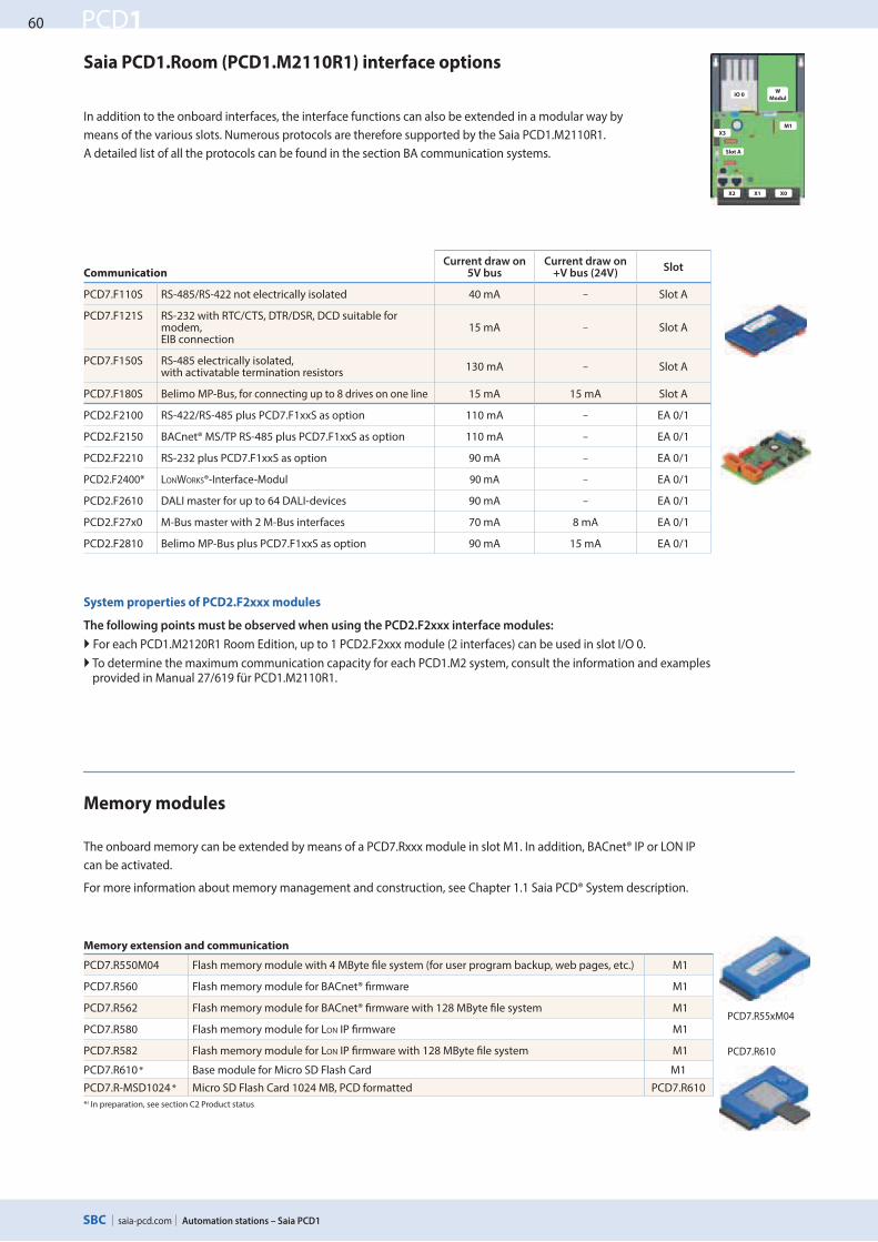
System properties of PCD2.F2xxx modules
The following points must be observed when using the PCD2.F2xxx interface modules:
For each PCD1.M2120R1 Room Edition, up to 1 PCD2.F2xxx module (2 interfaces) can be used in slot I/O 0.
To determine the maximum communication capacity for each PCD1.M2 system, consult the information and examples provided in Manual 27/619 für PCD1.M2110R1.
The onboard memory can be extended by means of a PCD7.Rxxx module in slot M1. In addition, BACnet® IP or LON IP
can be activated.
For more information about memory management and construction, see Chapter 1.1 Saia PCD® System description.
Memory modules
In addition to the onboard interfaces, the interface functions can also be extended in a modular way by
means of the various slots. Numerous protocols are therefore supported by the Saia PCD1.M2110R1.
A detailed list of all the protocols can be found in the section BA communication systems.
Saia PCD1.Room (PCD1.M2110R1) interface options
CommunicationCurrent draw on
5V busCurrent draw on
+V bus (24V)Slot
PCD7.F110S RS-485/RS-422 not electrically isolated 40 mA – Slot A
PCD7.F121S RS-232 with RTC/CTS, DTR/DSR, DCD suitable for modem, EIB connection
15 mA – Slot A
PCD7.F150S RS-485 electrically isolated, with activatable termination resistors
130 mA – Slot A
PCD7.F180S Belimo MP-Bus, for connecting up to 8 drives on one line 15 mA 15 mA Slot A
PCD2.F2100 RS-422/RS-485 plus PCD7.F1xxS as option 110 mA – EA 0/1
PCD2.F2150 BACnet® MS/TP RS-485 plus PCD7.F1xxS as option 110 mA – EA 0/1
PCD2.F2210 RS-232 plus PCD7.F1xxS as option 90 mA – EA 0/1
PCD2.F2400* LONWORKS®-Interface-Modul 90 mA – EA 0/1
PCD2.F2610 DALI master for up to 64 DALI-devices 90 mA – EA 0/1
PCD2.F27x0 M-Bus master with 2 M-Bus interfaces 70 mA 8 mA EA 0/1
PCD2.F2810 Belimo MP-Bus plus PCD7.F1xxS as option 90 mA 15 mA EA 0/1
IO 0
Memory extension and communication
PCD7.R550M04 Flash memory module with 4 MByte Zle system (for user program backup, web pages, etc.) M1
PCD7.R560 Flash memory module for BACnet® Zrmware M1
PCD7.R562 Flash memory module for BACnet® Zrmware with 128 MByte Zle system M1
PCD7.R580 Flash memory module for LON IP Zrmware M1
PCD7.R582 Flash memory module for LON IP Zrmware with 128 MByte Zle system M1
PCD7.R610 * Base module for Micro SD Flash Card M1
PCD7.R-MSD1024 * Micro SD Flash Card 1024 MB, PCD formatted PCD7.R610
*) In preparation, see section C2 Product status
61
saia-pcd.com
PCD1
Automation stations – Saia PCD1
54
32
1C
ab
ine
t
com
po
ne
nts
De
dic
ate
d
roo
m c
on
tro
lle
rH
MI V
isu
ali
zati
on
a
nd
op
era
tin
gA
uto
ma
tio
n
sta
tio
ns
Co
nsu
mp
tio
n d
ata
a
cqu
isit
ion
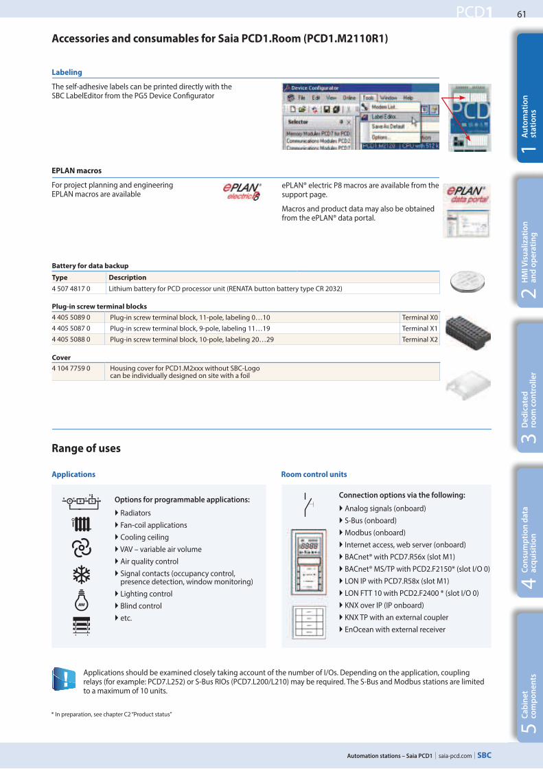
Applications Room control units
Options for programmable applications:
Radiators
Fan-coil applications
Cooling ceiling
VAV – variable air volume
Air quality control
Signal contacts (occupancy control, presence detection, window monitoring)
Lighting control
Blind control
etc.
Connection options via the following:
Analog signals (onboard)
S-Bus (onboard)
Modbus (onboard)
Internet access, web server (onboard)
BACnet® with PCD7.R56x (slot M1)
BACnet® MS/TP with PCD2.F2150* (slot I/O 0)
LON IP with PCD7.R58x (slot M1)
LON FTT 10 with PCD2.F2400 * (slot I/O 0)
KNX over IP (IP onboard)
KNX TP with an external coupler
EnOcean with external receiver
Battery for data backup
Type Description
4 507 4817 0 Lithium battery for PCD processor unit (RENATA button battery type CR 2032)
Plug-in screw terminal blocks
4 405 5089 0 Plug-in screw terminal block, 11-pole, labeling 0…10 Terminal X0
4 405 5087 0 Plug-in screw terminal block, 9-pole, labeling 11…19 Terminal X1
4 405 5088 0 Plug-in screw terminal block, 10-pole, labeling 20…29 Terminal X2
Cover
4 104 7759 0 Housing cover for PCD1.M2xxx without SBC-Logo can be individually designed on site with a foil
Accessories and consumables for Saia PCD1.Room (PCD1.M2110R1)
Applications should be examined closely taking account of the number of I/Os. Depending on the application, coupling relays (for example: PCD7.L252) or S-Bus RIOs (PCD7.L200/L210) may be required. The S-Bus and Modbus stations are limited to a maximum of 10 units.
Range of uses
Labeling
The self-adhesive labels can be printed directly with the SBC LabelEditor from the PG5 Device Conagurator
EPLAN macros
For project planning and engineering EPLAN macros are available
ePLAN® electric P8 macros are available from the support page.
Macros and product data may also be obtained from the ePLAN® data portal.
* In preparation, see chapter C2 “Product status”

62
saia-pcd.com
PCD1
M1
Slot A
X2 X1 X0
X3
142 61
14
2
Automation stations – Saia PCD1
Power supply 24 VDCWatchdog relay
RS-485 interface
Terminals for integral inputs and outputs
Terminals for op-tional connection
(slot A)
Ethernet connection(2 port switch)
USB port
Operational LEDs
Slot for communication interfaces
Battery
RUN/STOP button
Slot for memory modules and com-munication
Layout
The freely programmable E-Controller (PCD1.M0160E0) is a compact controller with a factory pre-load-
ed S-Monitoring application. For more about S-Monitoring and the loaded application, see below under
Chapter 4 „S-Monitoring“, section 4.8 „E-Controller“. Designed for compatibility with an electrical control
box, the E-Controller is suitable for installation in a power distribution unit or any restricted space. In
addition to integral I/Os, interfaces and web/IT functions, the PCD1.M0160E0 oVers further ways of
connecting various protocols. This controller is therefore ideal as a micro-controller or communications
gateway (e.g. EnOcean, KNX, BACnet ...) or for acquiring, logging and processing consumption data.
1.4.3 Saia PCD1.M0160E0 E-Controller
Power supply & connection plan Mounting Dimensions
on a \at surface
Further information is provided in the Saia PCD3 power supply and connection plan section and in Manual 26-875.
on top-hat rail (35 mm according to DIN EN 60 715 TH35)
Supply
Earthing bar
1.5mm2 / max. 25 cm
S-Monitoring application loaded
For more details, see Chapter 4
63
saia-pcd.com
PCD1
SNMP
Automation stations – Saia PCD1
54
32
1C
ab
ine
t
com
po
ne
nts
De
dic
ate
d
roo
m c
on
tro
lle
rH
MI V
isu
ali
zati
on
a
nd
op
era
tin
gA
uto
ma
tio
n
sta
tio
ns
Co
nsu
mp
tio
n d
ata
a
cqu
isit
ion
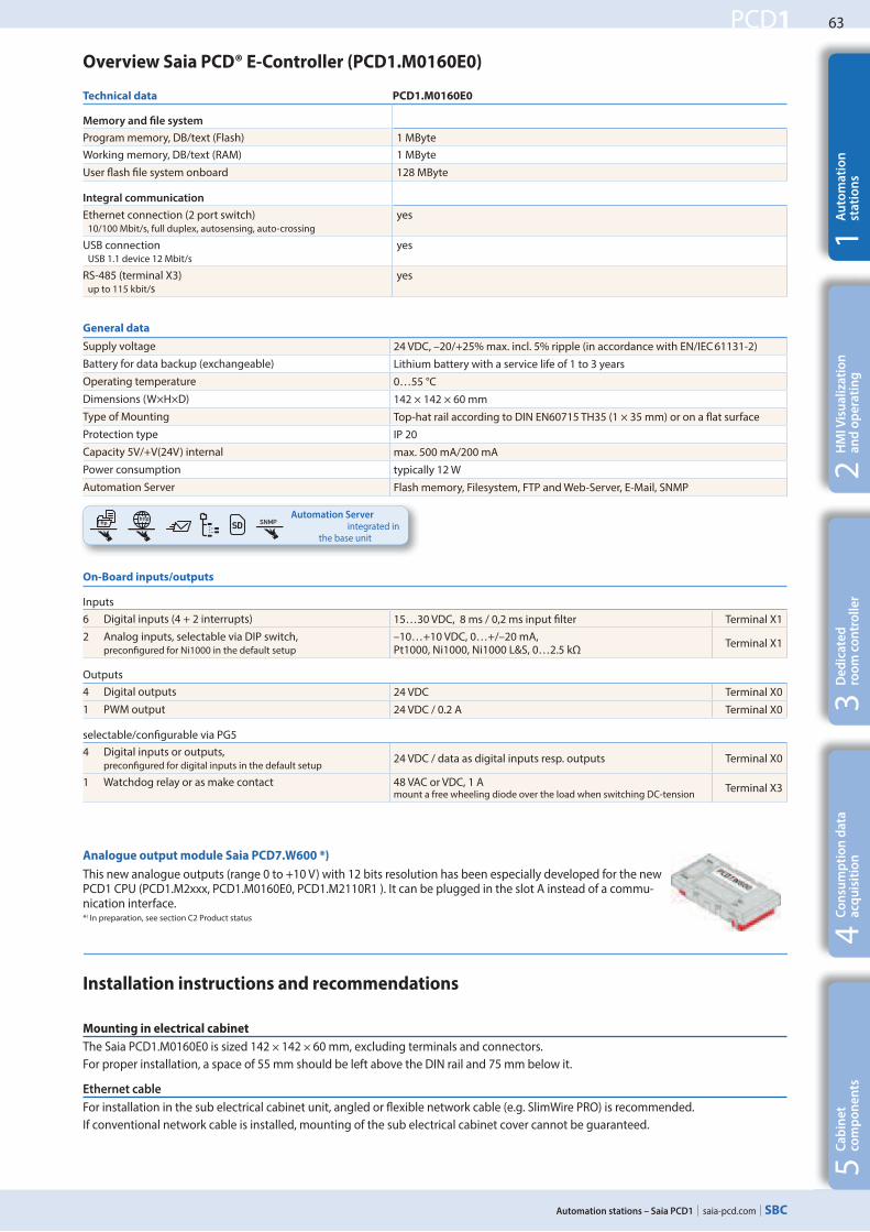
On-Board inputs/outputs
Inputs
6 Digital inputs (4 + 2 interrupts) 15…30 VDC, 8 ms / 0,2 ms input Dlter Terminal X1
2 Analog inputs, selectable via DIP switch, preconDgured for Ni1000 in the default setup
–10…+10 VDC, 0…+/–20 mA, Pt1000, Ni1000, Ni1000 L&S, 0…2.5 kΩ
Terminal X1
Outputs
4 Digital outputs 24 VDC Terminal X0
1 PWM output 24 VDC / 0.2 A Terminal X0
selectable/conDgurable via PG5
4 Digital inputs or outputs, preconDgured for digital inputs in the default setup
24 VDC / data as digital inputs resp. outputs Terminal X0
1 Watchdog relay or as make contact 48 VAC or VDC, 1 A mount a free wheeling diode over the load when switching DC-tension
Terminal X3
General data
Supply voltage 24 VDC, –20/+25% max. incl. 5% ripple (in accordance with EN/IEC 61131-2)
Battery for data backup (exchangeable) Lithium battery with a service life of 1 to 3 years
Operating temperature 0…55 °C
Dimensions (W×H×D) 142 × 142 × 60 mm
Type of Mounting Top-hat rail according to DIN EN60715 TH35 (1 × 35 mm) or on a aat surface
Protection type IP 20
Capacity 5V/+V(24V) internal max. 500 mA/200 mA
Power consumption typically 12 W
Automation Server Flash memory, Filesystem, FTP and Web-Server, E-Mail, SNMP
Installation instructions and recommendations
Mounting in electrical cabinet
The Saia PCD1.M0160E0 is sized 142 × 142 × 60 mm, excluding terminals and connectors.
For proper installation, a space of 55 mm should be left above the DIN rail and 75 mm below it.
Ethernet cable
For installation in the sub electrical cabinet unit, angled or aexible network cable (e.g. SlimWire PRO) is recommended.
If conventional network cable is installed, mounting of the sub electrical cabinet cover cannot be guaranteed.
Technical data PCD1.M0160E0
Memory and #le system
Program memory, DB/text (Flash) 1 MByte
Working memory, DB/text (RAM) 1 MByte
User aash Dle system onboard 128 MByte
Integral communication
Ethernet connection (2 port switch) 10/100 Mbit/s, full duplex, autosensing, auto-crossing
yes
USB connection USB 1.1 device 12 Mbit/s
yes
RS-485 (terminal X3) up to 115 kbit/s
yes
Overview Saia PCD® E-Controller (PCD1.M0160E0)
Automation Server integrated in
the base unit
Analogue output module Saia PCD7.W600 *)
This new analogue outputs (range 0 to +10 V) with 12 bits resolution has been especially developed for the new PCD1 CPU (PCD1.M2xxx, PCD1.M0160E0, PCD1.M2110R1 ). It can be plugged in the slot A instead of a commu-nication interface.*) In preparation, see section C2 Product status
64
saia-pcd.com
PCD1
RS-232
M-Bus
RS-485
M-Bus
PCD7.R55xM04
PCD7.R610
M-Bus
Automation stations – Saia PCD1
Plug-in screw terminal blocks
4 405 5089 0 Plug-in screw terminal block, 11-pole, labeling 0…10 Terminal X0
4 405 5087 0 Plug-in screw terminal block, 9-pole, labeling 11…19 Terminal X1
4 405 5088 0 Plug-in screw terminal block, 10-pole, labeling 20…29 Terminal X2
4 405 4919 0 Plug-in screw terminal block, 10-pole, labeling 30…39 Terminal X3
Battery for data backup
Type Description
4 507 4817 0 Lithium battery for PCD processor unit (RENATA button battery type CR 2032)
Accessories and consumables
Memory modules
For the parallel operation of S-Monitoring and BACnet® respectively LON, please note the instructions on the
support homepage www.sbc-support.com
Communication
Current consumption
at 5V bus
Current consumption
at +V bus (24 V)
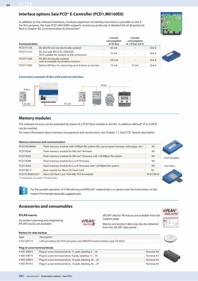
PCD7.F110S RS-485/RS-422 not electrically isolated 40 mA --- Slot A
PCD7.F121S RS-232 with RTC/CTS, DTR/DSR, DCD suitable for modem or EIB connection
15 mA --- Slot A
PCD7.F150S RS-485 electrically isolated, with activatable termination resistors
130 mA --- Slot A
PCD7.F180S Belimo MP-Bus, for connecting up to 8 drives on one line 15 mA 15 mA Slot A
In addition to the onboard interfaces, modular expansion of interface functions is possible at slot A.For this purpose, the Saia PCD1.M0160E0 supports numerous protocols. A detailed list of all protocols Xnd in chapter B2 „Communication & Interaction“.
Interface options Saia PCD® E-Controller (PCD1.M0160E0) M1
Slot A
X0X1X2
X3
EPLAN macros
For project planning and engineering EPLAN macros are available
The onboard memory can be extended by means of a PCD7.Rxxx module in slot M1. In addition, BACnet® IP or LON IP
can be enabled.
For more information about memory management and construction, see Chapter 1.1 Saia PCD® System description.
Connection example: M-Bus with external interface
ePLAN® electric P8 macros are available from the support page.
Macros and product data may also be obtained from the ePLAN® data portal.
Memory extension and communication
PCD7.R550M04 Flash memory module with 4 MByte Xle system (for user program backup, web pages, etc.) M1
PCD7.R560 Flash memory module for BACnet® Xrmware M1
PCD7.R562 Flash memory module for BACnet® Xrmware with 128 MByte Xle system M1
PCD7.R580 Flash memory module for LON IP Xrmware M1
PCD7.R582 Flash memory module for LON IP Xrmware with 128 MByte Xle system M1
PCD7.R610 * Base module for Micro SD Flash Card M1
PCD7.R-MSD1024 * Micro SD Flash Card 1024 MB, PCD formatted PCD7.R610
*) In preparation, see section C2 Product status

![str. 4–5 PCD3 Power - Sabur Warszawa › wp-content › uploads › 2016 › ... nr 1[49]/2012 ISSN 1898-522X str. 4–5 PCD3 Power jeszcze więcej mocy w sterownikach Saia PCD3!](https://static.fdocuments.pl/doc/165x107/60cbcba4744c740b5c175aed/str-4a5-pcd3-power-sabur-warszawa-a-wp-content-a-uploads-a-2016-a-.jpg)


![Maheswaran, H; Petrou, S; MacPherson, P; Choko, AT ... · Maheswaran et al. BMC Medicine (2016) 14:34 Page 2 of 12. self-reported income [20]. In addition, we recorded the total time](https://static.fdocuments.pl/doc/165x107/5f06cdef7e708231d419d1d7/maheswaran-h-petrou-s-macpherson-p-choko-at-maheswaran-et-al-bmc-medicine.jpg)