![Odnowa w Duchu Świętym. Wielkie zwiedzenie, tajna bron … · Spis treści 1.Intro 2.Cel zesłania Ducha Bożego 3.Amalgamat 4.Ni pies ni wydra[neither fish nor fowl] 5.Poznacie](https://static.fdocuments.pl/doc/165x107/5c78280709d3f2cd0e8c657b/odnowa-w-duchu-swietym-wielkie-zwiedzenie-tajna-bron-spis-tresci-1intro.jpg)
> g...L 01 paau noR se eap! s!y) uo puedxa ueo noR Inc! sJaiial Mau uJeal 01 Mog Jo eap! ay' IaS noR...
156
4.»1 9"I7 ors - u--)1>kti SE101`dJ8d0 Olab'l W`dH AO dd`d1S S51OdHS Oladl 1E1 a81Ia8 , >_ g" ' °L., `- ... ' IIlISd3 aNb' KNOIf1O 30O0 NEI`d31 ° - SNOI1S8f10 1S1 r JI1:lO3H1 OIa`dl WdH 01 8O WOEId f1OJl 35Ib1 01 3Sdf10O a3WWd1:1OOEld V 5b'2 9Sí2 -2y
Transcript of > g...L 01 paau noR se eap! s!y) uo puedxa ueo noR Inc! sJaiial Mau uJeal 01 Mog Jo eap! ay' IaS noR...

4.»1 9"I7 ors - u--)1>kti
SE101`dJ8d0 Olab'l W`dH AO dd`d1S
S51OdHS Oladl 1E1 a81Ia8
, >_
g" '
°L., `- ... '
IIlISd3 aNb' KNOIf1O 30O0 NEI`d31
° - SNOI1S8f10 1S1 r
JI1:lO3H1
OIa`dl WdH 01 8O WOEId f1OJl 35Ib1 01 3Sdf10O
a3WWd1:1OOEld V
5b'2 9Sí2 -2y

INTRODUCTION CQ WORLD! CQ WORLD! CQ WORLD! ... This is W----; W----; W----; ... Over!
If you've read this far, you may have already started on the road toward making that "call" a reality for yourself!
Yes! Amateur radio is fascinating! You can talk to the world from your "hamshack". You will meet new friends in Radio Clubs and in "Amateur Radio Nets". You will "handle traffic" and relay messages via the magic of radio. You may sometime be involved in saving lives by providing emergency communications during a natural disaster, or after an accident. In addition, it is almost a "sure-fire" thing that once you have your Ham ticket, you'll frequently enjoy the art of "rag -chewing" (just talking with other amateur operators from all over, on the air). Perhaps you'll be the type who enjoys the aspect of experimen- tation and building your own electronic equipment. Whatever "your thing" . . . you'll find that Amateur Radio is truly fun! fascinating! and a fantastic hobby.
In this PROGRAMMED STYLE book, you will find that learning is easy! We don't want to imply that learning comes without effort . . . but we know that you'll find that learning in "digestible bits" and getting virtually "instant feedback" as to whether you are grasping the key ideas, will be very helpful to your learning process.
The basic philosophy of the book is to have you UNDERSTAND CONCEPTS RATHER THAN MEMORIZE A GROCERY LIST OF FACTS! Wherever it is possible to have you learn to understand key principles and concepts, rather than have you simply memorize a fact .. .
we will do it!
Before we show you "how to use" the book ... take a look at the pictures below of just a few of the many available Amateur Radio activities that you will be able to participate in after you've studied this book. We hope these will inspire you to jump into the learning experiences of this book ... get your Amateur Radio license ... and truly travel the road "from 5 watts ... to ... 1000 watts!
h.< , _ _ . '
- o .. ' ,y 4 . -- 3`` lií
r
Y
o
,,.'
n.{
r . ,: ;It."`;1 .;.1
i^yrf ,,t' fi J -
A . A
6t -
`
-
W
®Copyright 1974, Radio Shack, A Tandy Corporation Company, Fort Worth, Texas 76109 PRINTED IN U.S.A.
2

is13eM 000 L o; s;;eM g 1,110.11. anow ol aiqe aq Alraopnb noA AelAi aJnpaooad 6uiuJeai uopionnsup pazpienppnppup 'paoed-;las spy; aouawwoo noA se ssaoons poo6 noA yspM aM ;p 6upsn ;o un; ay; me;s uay; 1:13n00 SS31:1601:Id a3 W Wt/liOOad., ay; asn o; Moy noA snnoys;ey; a6ed au; le nooi e arael )10
sJa;aweJed ieoupaia 6uunseaw Jo; ( W On e se o; pana;am sawp;awos) Ja;awpljnw e pue Cola 'sio;spsai an) sped asooi Ma; e 'Alddns JaMod a6e;ion aigeuen e si papaau sp ley; iie 's;oalomd ay; ;o ;sow J03 raoeyg oppea pooyaogy6pau JnoA woJ} ;sop leupwou ;e paipnboe aq ueo pue 'Iewpupw si papaau luawdpnba ay; ley; alay uop;uaw s,;ai
..5103('0ad ONIOa.. ho;eioqel ien;ae aq ueo sasioJaxa ay; jo Auew awos arnowd o; yspM Jo ;uawdpnba pue sued opuoi;oala opseq aney noA ;p 'Janannoy 'uopyse; ipouad pue Jaded e up sasiomaxa ay; ~pad ueo noA aigeipene sp ;uawdpnba ou ;i sAeM oM; 40 Jay;pa up 6upApn;s Jo; pasn aq ueo swaigoJd pue saspoJaxa aoi;oeJd ay; ley; sp nooq ay; 40 anneal 6up;saJa;up AJan Jay;ouy
uop;eop;uep Jo; Jeadde o;a 'sweJ6eip 'slmeyo 'sain;opd yopyM up uwnloo uoi;ewJo;up leuop;pppe ue sp Z uwnio0 'Alie;uappoui ;p MOura ;,uppp pue alayMawos ;no passpw noA asneoaq iepialew;o s;uaw6as a6ny Apn;sap o; paau noAley; wea4suMop AeM ;no 6uppup; saieu -iwiia spyl 6uppaaooud alo;aq papaau 6uppue;sJapun ay; lab op noA ley; ainsse o; Iepalew ay; up pieMraoeg ;unowe a;eudojdde ue ;iasinoA aloAoal Ala;eppawwp ueo noA 'ieua;ew ;o awei; Jeinopmed e pue;sJapun ;ou ppp noA ;p ley; sp anbpuyoa; raoegpaa; lue;sup ay; 40 A;neag a 4 ti abed aas 'aoinap spy; asn o; Moy uo suojloanp pa;ensnllp mod leua;ew 6upuJeai ay; y6noJy; ssai6oid noA se nooq ay; 40 suwnloo pe;upid ay; uMop arms noA;ey; aopnap Janoo ai13pl e sp sp41 ..1:13nO0 SS31:1901:id 433ININV:t1OOFId., algenow e 6upsn Aq asuodsai JnoA >payo Ala;eppawwp ueo noA £ uwnioo up ;up0draoayo e sueaw Aq AeM ieop;oeid e up ip iieoaa o; Jo 'uopiewio;up spy; asn o; parase uay; L uwnioo up uopletwo;up 40 (dais ai6ups) aweJ; e uani6 ame noA s;pg aigp;saópp news olup uaraoJq si leua;ew 341 ley; sp mooq spy; up uop;e;uasaJd ay; ;noge aop;ou IlonoA 6uiy; ;sn; 041
;e~; 6upop pue 6upuJeai pue 6upwJo;Jad pue 6upApn;s e o;w lp paia;ie "am aseo spy; up ;nq eapp awes a4; ;eyMawos a;eJod -looup o; pa;dwane "am mooq spy; up Mapnaa 'e;poad 'peaa :ame 6upuJeal;o sal-£ 041
)IOOB 3H1 1fO8d

USING THE "PROGRAMMED PROGRESS COVER"
Below is a sample of the "three -column" approach used in this book. An example is given
of how the "cover" is used to "hide the answer" for a checkpoint until you've had time
to give your answer ... then, of course, you would simply move the cover downward to reveal the correct answer . . . and to check yourself. To make a Programmed
Progress Cover, just cut a thin piece of cardboard, about 11" wide by 2-4" high;
then use it as illustrated.
INFORMATION REFERENCE
Ohm's Law states that electrical current is I)Illl:(:'I'I,Y related to Voltage. 'Phis means that if the applied voltage In a given
electrical circuit is doubled . . . Ihen, the circuit current will double.
VOLTAGE SOURCE
"PROGRAMMED PROGRESS COVER"
MOVE COVER DOWN AS YOU PROGRESS!
s
CHECKPOINTS
CHECKPOINT:
If the voltage input In the circuit shown in column 2 were tripled ... what would happen Io the circuit current.?
ANSWERS:
ll would triple! Note: "increase" would also be a good answer, but "triple" is a more precise answer.
d

0oy1ne) apPaW 7 Hassny A8
aiA3s ewes Sly; U! Jay;oue Aew aM pani1030.1 !WA S,4!
! >ooq s!y;;noge seep! pue s;uawwoo inoA ui pa3saia3ui aq Al¡euosiad p,1 'AeM ay; As
¡saipn3s JnoA ui noni poop
uo pue Z ia3de43 ui Apn3s AJoay; ui6ag osie 3ng uoi3en3is inoA 10} alge3ins se 0p03 ay3 Apn3s ol paaoo.ed uayl 6uiwil pue aoedg 4o soiueyoaw au_ pue apoo 40 spunog ay; 6ui;einwig 'a6en6ue-1 MaN p paµN L ia3deyo ui sydeJ6eied ay; peas
apoo ay; y;iM nJoM noA awi; awes ay; 3e Z Ja3dey3 uo 6uppoM ;ie3s pue peaye o6 wogs noA '(si se L Ja3deyo 6uisn Jo punos Aq) aseo Ja41ia u!
¡3i HoM noA }i 'voM 0,3! spue3s 1! se 3snf L ~ego asn-asay3 }o auo 01;061, ueo noA }1 AeM siy3 apoo ay; Wee! 03 noA affin am 'Cola 'me -a43-}}0 Apaa.qp suoissas aai;oeid apoa óuiniaoai }o a¡gedeo Jani9301 e 'spJoaai Jo sade; s,>aeys owes se yons) a¡geiiene poy3aw punos e aney noA apoo 6uiwea¡ }o poy3aw punos e o; ssaooe aney 3ou op oyen asoy3 10} Apeinowed mooq ay; u! papnpu! uaaq sey L Ja;dey3
apoo ay; 6uiwea-1- ia3dey3 ;noge ow!' e )11e; s,30-1
asuaon leiauao asuaon uemuyoal
asuaon aoinoN apoo ay; 6uiwea
:sJa3deyo b o3w nooq ay; papinip "am AeM ley; ;i asn os 'nooqylioM
/qe1 e aq o3 3ueaw s,;!-6uiipoop pue 6~164 inoA 404 saoeds mum(' ay; asn-sa;ou pue suoqeinnieo .104 aoeds 6umioM }0 s3oi si 04043 os paziue6Jo uaaq Apa;eiagqap sey noog 041
oipei weH }o 6uipue3sJapun poo6 e uie6 pue 1! asn ueo lie sdnoi6 news Jo Abel ymM wool ssep e
u! Jo-uoi3en3is Apn3s awoy e u!1! asn ueo noA ley; wio} e yons ui psluasaid si looq a41
3! 6u!op un} aney pue-(asiMla43o Jo 4080 e (ai,noA Jay3ayM) asuaoi¡ may; 106 0; sweH aq-pinoM diay 03 si 'wog s!y; }o asodind a41
sia3uiod pue suoi3sa66ns awos noA ani6 s,;a! MofJ
mooq HIo 03 noA paonponui "am 'NO
5

Chapter 1
LEARNING THE INTERNATIONAL MORSE CODE
A NEW LANGUAGE
Radiotelegraph code is a different language ... but it's a universal language! Fortunately, code
is not as difficult to learn as other languages. Thank goodness, there's no parts of speech, idioms, or conjugation of verbs to worry about. It really boils down to simply learning some
"sound patterns."
Because it is necessary to learn to identify "sound patterns" ... THE ONLY WAY TO PROP- ERLY LEARN CODE IS BY SOUND . . . AND BY SOUND ONLY! DON'T MEMORIZE WRITTEN CODE CHARTS!
For this reason we highly recommend that you practice the sounds AT EVERY OPPOR- TUNITY by ...
INFORMATION
SIMULATING THE SOUNDS OF CODE Before we begin to show you these "patterns in sound" mentioned earlier-let's look at a simple method of simulating code -like sounds.
Incidentally, we want to emphasize that you should learn sound pat- terns ... that is, complete character sounds, rather than individual dots or dashes. In fact it is very interesting to note that as one becomes more and more proficient in code, he not only hears complete characters (letters, numbers or punctuation marks), hut, whole -word sound patterns. Really expert code men can hear patterns far in ex- cess of single words. This last level of proficiency is really not needed for passing Amateur License exams, but many hams do like code so much that they achieve this by on -the -air experience.
For the time being, let's learn how we simulate dots and dashes.
A series of dots can be simulated by voice by a rapid repetition of the syllable "di" ... pronounced like the first part of the word did. This series of "di's" should all be run together in a staccato string. Try saying "di-di-di-dit." Notice that the last syllable has a "t" attached, denoting the end of the series. Try a string of 10, and keep trying until you can say them smoothly run together with a staccato, even repetition of each syllable. Don't get discouraged, you'll have a "trained tongue" with just a little practice.
Try some more "di's" - "di-di-di-di-di-di-drt". Don't worry about sounding silly-this is one of the best ways to get used to the "sound of code". Practice some more-OUT LOUD!
6

L
01 paau noR se eap! s!y) uo puedxa ueo noR Inc! sJaiial Mau uJeal 01 Mog Jo eap! ay' IaS noR dlay 01 aspJaxa ue saJaH dn way) x!w 01 ulsaq uayl 'SuluJeal aa,nof sJallal jo dnoJS Mau ay) u! saalla) aqi jo !pea J0J punos áy1 nnou>l noR lOaJ noif Ja1Jt! uo os pue 'pJ!gl e '11041 Sum awes 041 op pue Jallal Jagloue 01 uo anow '1.1041 Ja))at ley) Jo.; punos alp mow{ noR IaaJ n0R l!lun Jamo pue Jamo s!y1 leada2l pnol ino-Jallal ay uay) punos alp Res 'J019eJe99 Jo Ja))al Mau Rue Su!uJeal Rlle!l!u! uagM :a1oN
4e13-4eP-4eP = O 1!P-4eP-!P = 21
1!P = 3 Pp -!p -!P -!P = H
4eP=.L
Sa310t1aVH0 WOaNb'a 30 df1O1:19 1SliI3
'SONn05 OHO* 0Nv SONIIOS [131131 'SONnOs 1N3w313 3000 N33M138 SNO11V13a 1v71NiM73w 3.41 SMOMS 1[1014 SiMI
I'I'II'I'I'iT1I.'I'Tr11IIII'1'I'1'I'1'I'I
Jale) 5i91 JoJ uoseaJ 091 aas !pm no,r, dnoJS uan!S Rue u! sJallal g jo sdnoJS aallaeJd noR imp aaay puawwOaaJ 01 IueM aM dnoJS e u! sJallal aJow Jo OMI JO saiJas e Sutop uayM (Jalae.iega) Jal1a) gaea uaaMiaq awl Jo spun E Molle of Jagwawad saaiial jo sdnoJS waoJ oi wa91 Su!u!gwoa ÁJ1 'ua91 I! aney noR !Dun JalaeJeya yaea aallaeJd aa!IoeJd oi noR a>lit p 2vi sJalJeJeya wopueJ jo dnoJS isJ!J ay1 s,aJaH
leJnieu spa.; 1! [nun (I!p-yep-lp) 21 Jallal alp aa!1JeJd uagl wyiRyJ ay1 Jo )aaJ ay1 HZ 01 saw!1 MaJ e s!y1 RJ,1, pa)uaaae SuJeal pJOM ay1 y1!M ¡apoa Su!uJeal w,l aseagd 0y1 Res!u 01 asn p)noM noR wylRyJ ay) 01 Jel!w!s aq wogs wglRyJ ay,1, (yep ay) )uaaae) i!p-yep-!p :se papunos 21 Ja)aeJeya ay) aq lyS!w aJa4 RJI 01 auo pooS t!
sJalaeJeyo aallaeJd awos wJoJ 01 spunos yep pue ill) 091 Su!uigwoo RJI s,10q it48!J llH
(sl!p L Jo) spun z = spJOM uaaMlaq aw!1 0y1 pue c(yep ay1 se awes) awl) jo spun E = sJalueJe93 uaaMlaq awl) alp
'awll Jo 1!un L=(yew uo!lenlound Jo Jagwnu 'Ja)1a)) J01ueJe4a alSuls e ul sqep pue si!) uaaMlag au!' aq)
'awi) Jo swim E = yep ay) 1 37VdS 0[10M :aldwexa Jod s!g) o) pa)elaJ aq UP3 asta Su!y1
I
I St/ 110, 01 3DVdS d317VaVH7 -RJan3 aw!) Jo win I= 19p 091 ley) sueaw sig1 aw!1 JOJ auuaJaJaJ
3A11V1311 '011178 NO11vi1f10 3101
o 33VdS 1N31313 HV0
pJepueis Jno paJap!suoa s! ,.i!P alp imp uo!)eJlsn)p ay1 u! 939oN
110 aldw!s ai!nb R))eaJ
S1NIOdMO3H3 viva '8 33N31:13331:1
sI: spJOM pue sJalneJeyu '(gep e Jo 1!p e) sluawala uaaMlaq pasn Su!aeds 091 pue 'sqep pue slip jo sd!gsuo!le)aJ awn ay,1,
JNIWIl aNtJ 3OtldS 30 S3INt/H331A1 3H1
inoge alnulw e JoJ >IIeI s,lal :laalgns ay) uo aJ,aM a)!gM
Ja!)Jea paa!lueJd am si!p ole0aels 0y1 J0 uo!leJnp alp saw!) E inoqe aq pinogs sa)gellRs yep asay1 Jo g3e3 yep -yep-yep-yep-yea laaJ 0y1 108 al 0509) Jo 'os JO 'anlJ JO Su!Jls e RJ1
sJagieJ J!ay1 Jo slaeay 041 u!M 0) sa!qeq Áq pasn 'ep ep pJ0M 041 Jo Jley an!) paaunouoJd 'yep punos ay) Res am 'gsep e alelnw!s ol->lO
NOIlVWaO3NI

INFORMATION To help you gel started. here are some code exercises for you. Try lo accent the dahs ... allow 3 units of time between characters ... and 7 units of lime between "groups''.
If you can gel a frien(I \alto can "wart'. these letters anti groups to you; either by the di-dah method. or with a code practice oscillator, after you have thoroughly learned the letters by "didahing'' to yourself. you will find it quite helpful as receiving practice.
For most people. receiving code takes much more initial practice than sending code. We'll teach you to send ;i little later. Right now. concentrate on learning Io hear the sound patterns for each character . . . so no matter xvhere it "appears" in a group of code characters . . . you automatically say . or write down the correct letter when you hear its sound pattern.
REFERENCE & DATA Initial Exercise: (sound it . . . then say the leper-out loud.)
dah T; dah T; dah T; dah T; dah T; dah 'I'; dah T; dah T: dah T; dah T.
di-di-di-dit H; di-di-di-dit H; di-di-di-dit H; di-di-di-dit H; di-di-di-dit H; di-di-di-dit I -I; di-di-di-dit I -I; di-di-di-dit H: di-di-di-dit II; di-di-di-dil I -I.
dit E; dit E: dit E; dit E; dit dit E: dit E; dit I?; dit I?; dit E.
di-dah-dii N; di-dah-dit R: di-dah-dii R; di-dah-dit N: di-dah-dit R: di-dah-dil N: di-dah-dit R: di-dah-dil It; di-dah-dit R: di-dah-dil R.
dah-dah-dah O: dah-dah-dah O; dah-dah-dah O: dah-dah-dah O; dah-dah-dah O;
dah-dah-dah O: dah-dah-dah O; dah-dah-dah O; dah-dah-dah O: dah-dah-dah O.
Second Exercise: (say the sound . . . then the letter. etc.)
dah dah 'I': di-dah-dil N: di-dah-dil R: dit I?; dil E:
di-dah-dil R; dab T; di-dah-dit R; dil E: dah 'I'; dil E: dit E: dah-dah-dah O: dah-dah-dah O: di-di-di-dii H: di-di-di-dii I -I; dah-dah-dah O; di-di-di-dil II; dah T; di-di-di-dil 1-I; dan-dah-dah O: di-dah-dil N; di-dah-dii N: di-di-di-dii II; (lit I;: dil E; di-dah-dit R; dab 'I': di-dah-dil N: dah-dah-dah O; di-di-di-dil H; dit K.
CHECKPOINTS
CHECKPOINT
Letter Groups Exercise: Say the sound you read for each character . . . then, write down the letter you think it is, and when you've finished writing down the groups of letters . . . check yourself using the "Instant Feedback Cover" as appropriate.
1st:
2nd:
3rd:
4th:
5th:
6th:
7th:
8th:
9th:
1uth:
dit dab di-dah-dit dah-dah-dah dil di-di-di-dit di-di-di-dit dil dah dah-dah-dah dit di-dah-dit dah-dah-dah dab di-di-di-dil dah-dah-dah di-dah-dit dit di-di-di-dit dab dit dab di-dah-dit di-dah-dit dah dah-dah-dah dit di-di-di-dit di-di-di-dit dab dab dab dah-dah-dah dah-dah-dah dit di-dah-dit dah di-di-di-dit dah-dah-dah di-dah-dit dah di-di-di-dit dit di-dah-dit dah-dah-dah di-di-di-dit di-dah-dii dah-dah-dah dii dit
ANSWERS: 1s1: ETROE
2nd: HHETO 3rd: ERO')'H 4th: OREHT 5th: ETRRT
6th: OEHHT 7th: TTOOF. 8th: RTHOR 9th: THERO
10th: HROEE
8

6
`1!p 'I!P 8 1!p-yep1p N
`4eP-4e1)-4eP O '4eP .L 1!p-11ep-!P 14eP-4eP-4eP O !gel) I 1!P -4e1) -l1) N !!!P11) -!P -!P H '1!P 3
1!P 3 '1!p -yep -!p N !UP-yep-lp N
14e1) I l4eP-4eP-4ep O 'I!p-!P-lp-!P H `1!P -!P -!P -!P H '1!p1p-!p-!p H 'I!p :a
1!p :a '4ep .I. '4eP-4e1)-4eP O '1!P N I!P-!P-!P-!P H `I!P-4ep-!P N
'4e13-9eP-4eP O '1!P 8 '4eP .L
INIOd)N33H3
I!1) !p !P 11)
II yep -yep -yep
O 1!P
yep
1!P-11eP-!p N
astaiax3 adA1-6u!puas
1NIOd)133H3
op noA SP sasuo(Isad a111 .1ano)un Alale!.idoddde pue Iu!nlaaa.l du ;iulpuas .1ayl!a Is!I alp yxno.nll yl.iol pue 11a11y dtunl Alwopue.t ñldw!s uayl nori put! 'inns (yep -!p) punns inn do ap!s .IaIIa1 ay! .1at11!a .1an0) 01 ...iano7 n)11clpaa:l IueIsul.. ay asn 11113 nori MoN
S21;1.L:)d?It/1I:) INO(1NN21 ;10 d(ION:) .LS?11:I., ayI pals!I Is.i!1 a.ti a.1.111 L a1i11d (11 naey u:) :Moy sa.1a11 oI paau .n1 '1)1 lueM nuA se tl:tntu SP s.1a1a11,n111a 11) (Ill 0,11 s(yI aa!l)e.1(1 1)1 ssauan11e.10uu1 uMo .1110ñ asn nori la! 1Lam 'osta.laxa 1iuiniaaa.t aa!lae.itl 11 pue asia.taxa Iuipuas a:tilae.id P :11011I 111 .\unl uaas .1,\ .110Á 1)1yl ntoN ¡111i!.1 IId
I! ñ.1I s.la1 pu11 uuinlua sIu!u(lyaaya )111 01 paaao.lcl a))1ds ssal u1 aa11)11.uf a.inui nori o.v, mil! au!! P 1.11) .rlla11.n!11) .1u1) won ;mow 1n(1 uea am ,<11,t s14,1, asuo(Isa.1 Iaa.l.ula atll .ia,\o:tun 01 (a1111
11;1A 1:I MD! .1(1) ,i11e1110z!.1011 .ianu:( .1111 3.\0111 uayl punus a11 .es .1a1P11 e pun ñll11nlae 11!n1 nori 111tII us aueld 1r.1u1)x1.u1t1 P 1.11 3s1:1.1:(x) .1111 Ind II.an1 atuil ti!y.f. asun(Isa.( 1aa.1.(na a111 aas 1)1
au1i1 A.Iana .ii.I os .1.(nu:) 1:n:yp:1:1:1 1u111st11 al :1.01111 111 o.\etl 1.1111M 111)ri 1et11 us 11
x11 atuil aunrs )111 11! OUP 'a)11.(Is .1n.r.114103 u11:1 us (In s1111 Ias S.1a1 11a1! alp lnli an,nn. 111111 .wou >IO
:9!I II.nuA I! ñ.1,1,., lu!111 Is.111 IyY!ui nori se w.n(1.(a(I ul p.1e11
s11 ion pue unl au nl as!a.1.1xa s!yl pu1.l riIsnu!.1aS uu!I;1u!p.luoa s11!ys anilelncl!ur.w put! anliu1)l .111.1 'aria Itouli n1)< an!I oI ¡Ono auo sou ¡MoM uo os pue '.1aI)e.tey) Ixau ayI gum paa)oad uayl Allaa.t.toa I! papunos noA 1! aas o1 ySnoua .tel Isnl u."up ..1a.\(r,) 1a11(Ipa):1 1ll11suI.. a111 :1A0111 u)tll .1o1a11.n:ya
1C111 .10.1 1 Ili nos .1tll ñes u1 a.111 uatll nori . .1a1)e.leya :ull nori '(`1; Il.a.t1 ,r1,`a.wutl 'attiil s1t11, as!a.r(xa 1.tn.`!a).1.1 "Ill p!p ).tn s11
.1s!a.1.1" 1;11j1 .1n.1 (5.1a11a1) s.c.)lae.ieya lo I)s aunas atll asn
riai e Iu!lrin(1!uetti lo sa!ur.ya.nu a111 1111)(111 ñ.1.111N1
1,11011 nori I11111 .ía11)(1 si! lulucl sn(1 111 T1'1 u1 -Á.1>I e litlisn ua\a lnntll1.11 .1s1a.1.1\) a(Ll-,Yulpuas 11 no, amtY, pm: pu(11)du a)u)nllos sttll u.1nl sasmdaxa .u1.<1-1fu!n!))a.1 e s! tulue.nu si! Limo!) Iu11!.1.\i u,(11l ptinns at11 Iu1.i11.n1 s1t11 ltassan a.\ 1a1 ñ11u1 nori sv
s1u.lsa.t(la.1 pinos .ull .1.(Ia11.ietl) ,(yl lo yu!tIl ñ11r.)!Ieulolne nuri . .1a1)11.letla 1!
.lo punus all Y,ui.n!a11 u,(y.tt 1111. WO 1:11!.111 01 51 ;tu1t11 1.111:t0 .111 31a . 1a111 .1111 111 .111110 01 .011 .u( I1,10.11 11111 01 >1)11(1 .1t11 t110.11 Y,U1)I.1unt Ail 1111-111:1 1111 . . .11dun:xa .ío,1 unrli11 .(.1I 10.11! asla,laxa aa11))1.t(i ay1 aYuel.nua.1 uI 1111.1111 .111 1111)1) ))11))1.1(1 a.nuu p.(.1:1 !pis nori Iaa.l no. II i.(s1a.1a.1 sclno.l,) dal l('I.. I5.111 .inu, uu up nori in!) A1oII

INFORMATION Another practice hint (if you are fortunate enough to own a shortwave receiver) is to listen to a "code station" and see if you can pick out the first group characters you have learned. If you are careful to choose a station that is sending good "clean" code (proper spacing and timing), you will find this great sport and excellent practice. Incidentally, if you are considering buying a SW receiver, you might go down to the nearest Radio Shack store anti look over the variety they have. Generally you will find that they have an economical receiver that will be excellent for learning code and as a first ham station receiver'. If this is not practical at this time, perhaps you can find a friend who has a receiver that you can listen to.
We'll say it again . . the secret of learning code is practice, practice, practice.
If you've got the first group of letters clown so there is no difficulty recognizing their sound patterns-then proceed with the next group we'll introduce you to now. If you still need practice on the first group-then "recycle" yourself as required.
All right! Let's try a "letter groups" exercise for this second group of characters.
REFERENCE & DATA
SECOND GROUP OF RANDOM CHARACTERS
dah-dah = M dah-dit = N di-dah-di-dit = I. di-di-dah-dit = F di-dah = A di-dit = I
dah-di-dah-dit = C
Note: Remember lo practice each character over and over saying the sound first, then writing and/or pronouncing the letter until you know its sound pattern . . . then move on to the next one. To refresh your memory on how this is done, refer back to the initial exercise for the "FIRST CROUP OF RANDOM CHARAC'T'ERS" on page 7.
CHECKPOINTS
CHECKPOINT
Say the sound you read for each character . . then write down the letter you think it is. When yuu'\e finished writing down the groups of letters . . . check yourself by using the "Instant Feedback Cover" as appropriate.
LETTER GROUPS EXERCISE 1st: dah-dah dah-dah dah-dit
dah-dit di-dah-di-dit 2nd: di-di-dah-dit di-di-dah-dit
di-dah-di-dit di-dah di-dit 3rd: dah-di-dah-dit dah-di-dah-dit
di-dah di-dah di-dit 4th: di-dah-di-dit di-dah-di-dit
dah-dit di-dah dah-dit 5th: dah-di-dah-dit dah-di-dah-dit
dah-di-dah-dit dah-di-dah-dit dah-di-dah-dit
6th: di-dit di-dit di-di-dah-dit di-dah-di-dit dah-dit
7th: dah-dah di-dah dah-di-dah-dit di-dit di-dah-di-dit
10

11
I!P'!p-4eP-!P I!P-'p-yeP-!p yep -yep -yep pp -yep -q3
pp-yep-lp yep -up I!p pp-yep-lp-w 1!p 1p 1!p -yep -p 1!p-tplplp tip :418
yep yep -!P 1!P I!p'!P'!P'!P I!P-yep-'P l!P
l!P-!P-!P-!P yep yep -!p pp'4eP'!P-!p pp'4ep-!p 1!P
I!p-'p-'p-!p yep yep -yep -yep 4ep-L ep :41G pp -yep yep -yep -yep yep -yep -yep yep
pp'4eP-!P yep -yep -yep 1!p-4ep'!p 1!P -!P I!P 1!P'!P !P'!P yep :419
I!P 4eP'4eP 4eP-!P !p'4ep l!P'!P'4eP-!P up'11-yeP'!P 4eP'!P 4eP
I!P yep -yep yep -yep -yep pp -!p -'p -'p :418 pp -!p -yep -!p I!p I!p I!p-yep-!p-lp
1!P I!P-4eP iP up I!P'!P'!P !P yep 1p 4ep'4ep yep -yep -yep 1!p -yep -!p :4117
yep I!P'!P 1!P -!P -'P -!P
I!P yep yep -!p pp -!P -yep -!p yep 4ep-!3 yep -yep
4ep 4eP-!P up-4eP-!p 4eP-4eP 4eP-!P up'4eP'!P-yeP
1!P -yep yep -!P up'yep-!p-yep :pul I!p'4ep yep-ip yep -yep
4ep yep -!P pp'4eP-!P-!p I!P 1!P -!P -!P -!P yep :Isi
3sI0a3x3 saaonn s11O3Nt11130s1w
1NIOd)103H0
WDHNI :4101 33D33 :41s WNdNW :416 NHN'l1 :416
113V:1 : 4143 1b'HDD :ptE 1DHW :41L 'VW :pul
Mldll :419 'iNNLNW :1St :Sli3MSNt1
yep'4ep pp'yep-!P'4ep yep !p I!p yep 111-!1) :4101
yep -yep pp -yep 4ep-!p pp -yep yep -yep :416
1!P'!I)-4e13'!P !p -!p lup-yep-lp-yep 4eP-!P I!3 -4e3 -!P -!P :419
{; utunlua u! asl:l.r,lxa swam sn(1autrlla:lslul au 1 Á.i1 '11au.nral s.ua11111 ,lo sdno.tll omI 1s.tlj ay l amey n(1A Ieyl 111alnuuo:1 a,utr noA ua4M t11a41 1ali.tn 1.00A1 nnA !Is a:1ll:nr.td .to] 7 huir 1 sdnn.ili liu!uuluto:l Á.tl ua41 .. 11(11111 ut Ilam (Ino.t:i Ituu:ras a41 amry nu,i :Luis :.10 nuA uatlM tlnlLtil SiI :yl .n11 It11) nnÁ se 1:11ryltao:l Iuelstll., ;nuliu!sn a:1il:ur.ul liutituas lawliutAia:rl.t aAtli Innt 01 axed uu Yu!Is!I ..c1(101 -I:) (IN(YMS.. ay1 n1 1:11r4 l.taA:N r.nli 1! 101) MoII '>I.O

INFORMATION
How did your first encounter with "real words" go? As you can see, with a little ingenuity, you can develop other word lists using the letters from the first two groups you've learned for further practice.
Let's move on to our third group of random letters now.
Time to try a "letter groups" exercise for this third group of characters.
12
REFERENCE & DATA
THIRD GROUP OF RANDOM CHARACTERS
di-di-dit = S di-dah-dah = W dah-di-di-dit = 13
dah-di-dit = I) dah-dah-dit = G dah-di-dah-dah = Y dah-dah-di-dah = Q
Note: Remember to say the sound (out loud), then the letter-until you know its sound pattern . . . then move on to the next . .
and so on.
CHECKPOINTS 9th: di-di-dah-dit di-dah di-dit dah
di-di-di-dit dah-di-dah-dit di-dah-di-dit dit di-dah di-dah-dit di-dah-dit di-dah dah dit
10th: dah-dah dit di-dah dah-dit di-dah-di-dit di-dah dah dit di-dah-dit dah-di-dah-dit di-dah-dit dit di-dah dah dit
ANSWERS: 1st: THE FAT MAN
2nd: CAN CAM RAT 3rd: MAT LATE HIT 4th: 5th: 6th: 7th: 8th: 9th:
10th:
ROME THERE FEEL HOME TALL NAME THEIR OR MOON MOTHER FATHER HEAT THREE FEAR ROLL FAITH CLEAR RATE MEAN LATER CREATE
CHECKPOINT
Use the usual procedure here! That is: say the sound . . . then write clown the letter you think it is. After completing the exercise. check yourself with the "Instant Feedback Cover".
THIRD LETTER GROUPS EXERCISE
1st: di-di-dit di-dah-dah di-di-dit dah-dah-dit di-di-dit
2nd: di-dah-dah dah-dah-dit di-dah-dah di-di-dit dah-di-di-dit
3rd: dah-di-di-dit dah-di-dit dah-di-di-dit dah-di-dit dah-di-di-dit
4th: dah-di-dit dah-di-di-dit dah-di-dah-dah dah-dah-di-dah dah-di-dah-dah
51 h: di-dah-dah dah-dah-dit dah-dah-dit di-dah-dah dah-dah-di-dah

Cl
¡1! le )ali slal put! 'uwnlo:) prly) ay) 01
paa:wd ).)yeyd)e ay) roJ turn)) ol paau noA srallal jo dnorW Ise! ayi un as!:).iaxa sdno.ix rallal e .ioJ Apea] a.i no,k ¡suo!leln)erWuoa
¡paa:)ord uayl llaM dno.i1 ylJnoJ s)yi weal s,lal -ND magi Mou)I noA l!lun asayl an!lae.)d :aloN
Z = 1!P-!P-4eP-4ep X = 4'P-!P-!P-4eP
A = 4eP-'p-!P-!p I7 = 4eP1P1P
d = 1!p-yep-4ep1p X = 4eP-iP-4eP
= 4e13-4EP-4PP-!P
Sa313vavH3 woaNva 3o dnoaJ H1ano3
ADsMS :4101 bMwM :41s BbASD :416 AÓABu :4i6 AuDsu :418 tunas TrE aSbMA :416 tSMDM :puz ADatS :419 SaSMS :1s1
:Sa3MSNV
4e13-4eP1P-4eP 1!p -yep -yep I!3-!3-!p-4ep
yep-yep-lp 1!P -!P -!P :4101 pp-LP-!P'Lipp
4ep-!p-4ep-4ep yep-4ep-!p'4ep 1!p -!p -1p 14) -yep -yep :416
4ep-yep-!P-4eP I!P-!P-4BP 1!P-4eP-4eP
I!p-IP-IP-yep 1!P -!P -yep :419 1!p -!p -yep
pp -'P -'P 4ep-!P-4eP-4"P yeP-4ep-10 yep-4ep-)p..yep :416
yep-4ep-!p-4ep 1!P-yep-4eP pp -!p -yep
I!P-!P-!p-yep 1!p -431p :919
dnaiá ay) Jo.' sasi:).)axa a.)!Iaerd ay) oI paa:)orcl 'dnorli ayI U! srailal ay) Ile 1lu!uaeal .ia)Jd dnoil ay) u! sralal a4) Ile n)u)I nori )llun 'up os pue dnor;l ay) u! auo Ixau ay) o) uo anon) 'uay) 'Ham I! Xu!ureal ra1JH .r)I:)e.ir.y:) ley) .ioJ uralled punos ay) Mou)I noA l!lun :saw!) Auow siyl liUiloaclar puo raila) ay) xu!:)unouodd ro/pue UMop ñUIIWM uayl raloe.)ey:) ayi .)oJ punos ay) lu!ries sueaw s!y,I, sdnorU railaea ay) roJ aney noA se a.mpanord awes ay) as11 layeydle ay) .ioJ s.)allal jo dnorW Ise) ay) Uu!ureal Jo )Ise) ay) Ie la;i s,lal 'os
apo:) Wu!ureal Jo ired llna!J.IIp 1sUu1 ay) payslldwo:)ae AI)ear ane9 noA . uoiyseJ wopuer u ui wayl reay noA uayM -layeydle ayI u! sial la' ay1 Ile .ioJ suralled punos ay) Moui noA uayM layeyd)e ay) alaldwo:) II!M yo!yM 'dnorx ylrnoJ ay) .ioJ ripear Mou are noA uMop s.iallal lo sdnorl aaryl Isr!) ay) aney noA 11 ¡learg

INFORMATION
Ilope you did well on this exercise. You have now learned the twenty six letters in the alphabet. just for good measure, we suggest that you try the sending and receiving practice using the "Instant Feedback Cover" technique on letter groups 3 and 4, just as you did for groups 1 and 2. After you are sure you have all twenty six letter sound patterns pretty svell in mind, we want you to try the "mixed code groups" practice in the exercise shown in the third column. When you're ready ... give it a try.
14
REFERENCE & DATA CHECKPOINTS
CHECKPOINT FOURTH LETTER GROUPS
EXERCISE 1st: di-dah-dah-dah di-dah-dah-dit
di-dah-dah-dit di-dah-dah-dah dah-di-dah
2nd: dah-di-dah di-dah-dah-dit dah-di-di-dah dah-di-di-dah di-dah-dah-dit
3rd: di-dah-dah-dah di-dah-dah-dit dah-di-dah dah-di-di-dah dah-di-dah
4th: di-di-dah di-di-di-dah di-di-dah di-di-di-dah di-di-dah
5th: di-di-di-dah di-dah-dah-dit dah-di-dah di-dah-dah-dah di-di-dah
6th: di-di-di-dah di-di-dah dah-dah-di-dit dah-dah-di-dit dah-dah-di-dit
7th: dah-dah-di-dit dah-di-di-dah dah-di-di-dah dah-dah-di-dit di-dah-dah-dah
8th: di-dah-dah-dit dah-di-dah di-di-di-dah di-dah-dah-dit dah-di-dah
9th: di-dah-dah-dit dah-dah-di-dit di-di-dah di-di-dah di-dah-dah-dah
10th: dah-di-dah di-dah-dah-dit di-di-dah di-di-di-dah dah-di-di-dah
ANSWERS: 1st: JPPJK 6th: VUZZZ
2nd: KPXXP 7th: ZXXZJ 3rd: JPKXK 8th: PKVPK 4th: UVUVU 9th: PZUUJ 5th: VPKJU 10th: KPUVX

.LHSI3 :4191 333O.L :4151
NIN/1f1V :4161 XM/1fl.L :41E1 DBVZA :41ZL IHOd3 :41LL
NW DII :4101 S2IbdO :416
aDflNZ :418 AASdIN :41L Í9aHfl :419 adH[4 :415
Nd2i.L!\ :416 XZAMII :p1£ Sbowx :puZ
IO33H :lsl :Sti3MSNV
4eP I!P-!P-!P-!P I!P-'P-!P 1!P -!P 1!P 1!P 1!13-40P-IP-4eP I!P-4eP-!p-4eP
yep -yep -yep 4eP
1!P-4eP 4eP-4eP 4eP-iP-!13-!p 4ep-113-!P 4eP1P
49)-!P-!P-4eP 4"P-4eP-!P 4eP-!P-!P-!P 4eP-!P-!P 4eP
1!p-4ep-!p-4ep 11P-!p-1p-4eP 4eP-!P
1!p-!P-4eP-4ep 4ep-4ep1p-4ep 1!p -!p /!p -!P -!P -'P
l!P-4e3-4eP 11P-4eP-!P-!P 1!P PP -4°13 4eP-11°P l!P-!P-4eP-!P
4eP-!P-9eP 4eP-4ep-4eP-IP I!P-!P-!P
I!P-4 eP-!I) 4eP-!P-4eP-4 eP 1!P-4eP-4eP-!p 4RP-4BP-4"P
1!p-!p-4ep 1!13-4eP-!p-4eP 1!P-!P1P-4RP
4e131P 1!P-!p-4e13-4eP 4eP-4RP1P-4IP
4eP-!p-!p-!P l!P-'P-!P 1!p-4ep-49)-!p 4e13-4eP
4eP-4°P-4eP-IP 1!P-4eP-4eP 1!P-!P-4BP 4eP1P 1!P-!P1P-4eP
1!p-!p-4ep 1!P-4RP-1P-!P 1!P -!P -'P -!P
4eP-4BP-4IP-!P 1!P-!P-4eP-!P 1!P-4eP 1!P-4e3-4eP-!p
I!P-4eP1P 4eP 4"P-!P1P-!P 4eP-!P-!P-4eP
1!P-!p-4BP-4RP 4e13-4eP1P-4eP 9PP-4°P-!P 4eP1P-!P
1!P -!p -!P 4eP-!P-4eP-11eP 4eP-4eP-4eP
4e13-4eP 4eP-!P-4eP l!P-!P 1!P-4eP-4eP
1!P 1!P-4e13-!P-4eP 4eP1P
:14191
:4191
:4161
:41EL
:41Z1
:411 L
:4101
:416
:419
:411
:419
:415
:4 ft
:puZ
:1st
3SI31:13X3 Sdf1O1:19 3a03 a3XI1A1 138VHd1V 1t11O1
0101S )IoeyS O!pe}J 1e301 JnoA le Olqel!e+1e s,ll enoge peleAlsnll! pioo0l:i 01)03 e4l se Lions me Bu!weel e esn ol noA e6in em Jellel 43e0 ez!u6000u pinoys noA pue epoo;o spunos e4l LiIIM peo en,no/l MoN
LUL UU'hRlUn ulur, 1I11IN hiSIOIlllldl SMOSS3101
35Hl03 9:111Wf)38 3003 ~ bVlM1VNN31N1. v> >r

INFORMATION
How did it go? You should have detected from this exercise the letters you are weak on. You should, of course, work on your weak ones until you have them as well as the others. Let's say again, the secret is PRAC'T'ICE! PRAC'T'ICE! PRAC'T'ICE! "Off the air" practice in receiving is really the best . . . providing you listen to a station sending "clean" code. The best vvay Io do this at this point in your learning process is to listen to some of station W1AW's code practice transmissions.
If you don't have a receiver that will receive these frequencies you might want to run down to your nearest Radio Shack and look over their selection. As we said before . . . the hest practice in the world is listening to the sounds . . . and listening to them being well sent . . . so get a receiver, or the use of one if al all possible. Take advantage of the premium practice available from W IAW. You'll find that you will progress much faster in code if you'll do this. Good luck!
As you listen to radio stations sending code, you will discover that they send other characters than just the 26 letters in the alphabet. Pur that reason, let's move into the area of learning the numbers and important punctuation. By the time you learn these if you have been faithfully practicing . . . you should be ready In take the Novice Class License Code lest.
Here's the numbers study list. See if you can determine the unique pattern of sounds that were developed for communicating the numbers via code.
Did you catch the logical pattern that was developed for the num- bers? WATCH OUT 't'I-IOl1Gl-l! The temptation is going to be to "count" the dits or dabs . . . then try and think out which of the numbers it is. You must learn to hear the TO'T'AL CHARAC'I'I;R SOUND as one unique sound you recognize, and do no start counting the elements which make up a character.
REFERENCE & DATA CHECKPOINTS
W1AW CODE PRACTICE SCHEDULE
Practice is transmitted three times a day during the weekdays and twice a day on the weekends. On weekdays, the times are 9:00 A.M. NS'I', 7:30 P.M. EST and 9:30 P.M. EST, and on weekends the P.M. schedules are maintained. For the beginner, the best times for listening are: 9:00 A.M. Monday. Wednesday. and Friday and 9:30 P.M. on Sundays, Tuesdays, Thursdays, and Satur- days. At these times W1AW sends practice at speeds of 5, 7'/2, 10, 13, 20 and 25 WPM (words per minute). As you progress you will find that the 7:30 schedule EVERY night is a good one as they send al 10. 13 and 15 WPM for practice purposes. All these transmissions are made simultaneously on the following frequencies: 1805, 3580, 7080, 14,080, 21,080, 28,080, 50,080 and 145,588 kHz. (If your receiver dial is calibrated in Megacycles, Mc., or Megahertz, MHz., simply put the decimal point in the above named frequencies BACK three places from the right. Poi' example 14,080 kHz = 14.08 Mc. or MHz.)
NUMBERS
di-dah-dah-dah-dah = 1
di-di-dah-dah-dah = 2 di-di-di-dah-dah = 3 di-di-di-di-dah = 4 di-di-di-di-dil = 5
dah-di-di-di-dit = 6 dah-dah-di-di-dit = 7
dah-dah-dah-di-dit = 8 dah-dah-dah-dah-dit = 9 dah-dah-dah-dah-dah = (this is the way
we write zero tu avoid confusion with the letter 0)
16

Ll
IfeMr\Ue way) MOM! O) paau IIno/f ssetJ leJauaJ JOJ
a:)uls ÁeM at1 JO inn watll 'al pue 'Wall UJeal pUe l)eelll'. nti 01 hilly 1.u~ I! OS ' Isa1 ato JO uO!IJOII JNIQNBS at) xu!.nlp uo!I -enl:lund puas 01 paJIl1I)aJ al if nu! noif ',1.1111
u011nniutind anlaaa.l 01 pa.I!nbaJ al IOU
II!M nOrf Isal iiU!n!aDa.I awn) asuaall SSV IJ íIJI!\ON 1)41 Un into JanaMOy 'iftlJOMaloti SI II IfeM Il:nsn ayI asayl a:l!oaeJd :aloN
OI.IeUI 'tints leuolie!p) 2IV11
NOI,I.3V21.4 = I!P-IIPP-!P'!1)-4PP UnISSIwSUnJ1
JO) >INOM :IO (IN:I = 4eP1P-IIPP-!P1P1P
)2IV Sl'. t1:)Il1.IM -SOW !I:111105)
:)VSS:I :10 (IN;1 = I!P-4eP-!P-4PP-!1)
),LÚ SP. UaIIIJM MU] I iaUlI1S)
I I5V(I :I'I1t110(1 = 4eP-!P-!P-!P-4PP
>2IVIN NOI.LS:11 = I!3-!P-4eP-40P-!P-!1)
VW1N0J = 4PP-4eP-!P-!P-4PP-4PP (I0I21:IcI = 4PP1P-40P-!13-4PIP-!P
S3Jt/SS3W 3003 NI a3Sf1 JIINOWW00 N011vfllONfld
asuani o!peg JnaoewV IsJ!J ley) du!1)a1 o1 ÁeM Jno/f uo !lam 'auo slyl gpV UOÁ Jl Ja)deya apoJ asJoiN teuo!leu.lalui ay1 Wu!uJeai alp JOJ lno)iaa4J leu!d éU!n!aUaJ Jnolf sop Jap!suoJ uo!lenlaund pue 'sJagwnu 'sJa)Ial JO as!aJaxa
..JaylaWol IIP I! Ind., s!41 J,L ,.iJaylalol IIP ! Ind.. s,1a'I i>I.O
vOI oenlaund pasn flluanhe.IJ aiow ayo JO awns 1ulurnal 'sI ono puny in (1uI lxau ayI Uo paaaoJd '(IN(lOS A8 ,,.Ialndwo:) le:)!Woloty !u0/< Ui p.)liotr.Ie:) Ham sJagwnu ay' aney n0Á a.lns ale noñ uatM
weyl .IuJ punos ale!JdOJdde ayI atos!yM JO 'tes 'Uo!ysei wopueJ e UI s.laywnu ato lP Wu!)lool al!y.nn pun=. Jann,) )iiegpaaa oueosul ayl y1!M spunos ayl ñu!Jan03 ñy a:)!i:n'Jd ,liwpuas 01 paa:)uJd uayl sueaw I! noonuMop a1iJM uayo ')unos at Ifes aI Ilann sJa1:)eJey:) ayo Ile Mou)i nnA t!Iun 'IsJ!J a:)!o:)eJd xuinla:)a.I,. Jo a.Inpa:w.ui lensn ayl asf1

Code Receiving Checkout-Conglomerate of Straight Text, Mixed Ciphers, Numbers and Punctuation
Line 1-dah di-di-di-dit di-dit di-di-dit di-dit di-di-dit
Line 2-di-dah di-di-dah dah-dit di-dit dah-dah-di-dah di-di-dah dit
Line 3-dah-di-dah-dit dah-dah-dah dah-dit dah-dah-dit di-dah-di-dit
Line 4-dah-dah-dah dah-dah dit di-dah-dit di-dah dah di-dit
Line 5-dah-dah-dah dah-dit dah-dah-dah di-di-dah-dit
Line 6-di-dah-dah dah-dah-dah di-dah-dit dah-di-dit di-di-dit
Line 7-dah-dah-di-di-dah-dah dah-dah di-dit dah-di-di-dah
Line 8-dit dah-di-dit dah-di-dah-dit di-dit di-dah-dah-dit
Line 9-di-di-di-dit dit di-dah-dit di-di-dit dah-dah-di-di-dah-dah
Line 10-dah-dit di-di-dah dah-dah dah-di-di-dit dit di-dah-dit di-di-dit
Line 11-di-dah dah-dit dah-di-dit di-dah-dah-dit
Line 12-di-di-dab dah-dit dah-di-dah-dit dah di-di-dah di-dah
Line 13-dah di-dit dah-dah-dah dah-dit di-dah-di-dah-di-dah
Line 14-di-dit di-di-dah-dit dah-di-dah-dah dah-dah-dah di-di-dah
Line 15-dah-dah-dit dit dah dah-di-dah-dit dah-di-dah-dit dah-dah-dit
Line 16-dit dah di-dah-dah-dah-dah dah-dah-dah-dah-dah dah-dah-dah-dah-dah
Line 17-di-dah-dah-dit dit di-dah-dit dah-di-dah-dit dit dah-dit dah
Line 18-dah-dah-di-di-dah-dah dah-di-dah-dah dah-dah-dah di-di-dah
18
Line 19-di-di-di-dit di-dah di-di-di-dah dit
Line 20-dah-di-dit dah-dah-dah dah-dit dit di-dah dah-dit
Line 21-dit dah-di-di-dah dah-di-dah-dit dit di-dah-di-dit di-dah-di-dit
Line 22-dit dah-dit dah di-dah-dah-dah dah-dah-dah dah-di-di-dit
Line 23-dah-dah-dah di-di-dah-dit di-dah-di-dit dit di-dah di-dah-dit
Line 24-dah-dit di-dit dah-dit dah-dah-dit dah di-di-di-dit dit
Line 25-dah-di-dah-dit dah-dah-dah dah-di-dit dit di-dah-di-dah-di-dah
Line 26-dah-dit dah-dah-dah di-dah-dah dah-dah-di-di-dah-dah
Line 27-di-dah di-dah-di-dit di-dah-di-dit dah-di-dah-dah dah-dah-dah
Line 28-di-di-dah dah-dit dit dit dah-di-dit dah dah-dah-dah
Line 29-dah-di-dit dah-dah-dah di-dit di-di-dit dah-di-dah-dit
Line 30-dah-dah-dah dah-dit dah di-dit dah-dit di-di-dah dit
Line 31-di-dah-dah-dit di-dah-dit di-dah dah-di-dah-dit dah di-dit
Line 32-dah-di-dah-dit di-dit dah-dit dah-dah-dit di-dit da h -di t
Line 33-dah-dah-dah di-dah-dit dah-di-dit dit di-dah-dit
Line 34-dah dah-dah-dah di-dit dah-dit dah-di-dah-dit di-dah-dit
Line 35-dit dí-dah di-di.-dít dit dah-di-dah-dah dah-dah-dah
Line 36-di-di-dah di-dah-dit di-di-dit di-dah-dah-dit dit dit dah-di-dit
Line 37-di-dah-di-dah-di-dah dah-dah-di-dah di-di-dah-dah-dah
Line 38-di-di-di-di-dit dah-dah-dah-dah-dah dah-di-di-dit dab
Line 39-dah-dah di-dah-dah-dit di-di-dit di-di-di-dah-dah dah-dah
Line 40-dah-di-di-di-dit di-dah-dah-dah dah-di-di-di-dah
Line 41-di-dah-di-dah-dit dah dah-dit dah-di-di-dah
Line 42-di-di-dah-dit dit di-dah-dit dab di-di-di-dit dit
Line 43-dah-dah-di-dah di-di-dit dah-dah-dah dah-dah-dah dah-dah
Line 44-di-dah-di-dah-di-dah dah-dah dah-di-dah-dah
Line 45-di-di-dit di-dit dah-dah-dit di-di-dit
Line 46-di-dah-dah dit di-dah-dit dit dah-dit dah-dah-dah dah
Line 47-di-dah-dah-dah-dah dah-di-di-dah-dit di-di-dah-dah-dah
Line 48-di-dah di-di-dit dah-dah-dit dah-dah-dah dah-dah-dah dah-di-dit
Line 49-di-dah di-di-dit dah-di-dah-dah dah-dah-dah di-di-dah
Line 50-di-dah-dit di-di-dil dah-dah-di-di-dah-dah
Line 51-di-dah-dah dit di-dah-dit dit dah di-di-di-dit dit
Line 52-dah-di-dah-dah di-di-dah-dah-di-dit
Line 53-di-di-di-dit dah-dah-dah di-dah-dah-dit dit
Line 54-dah-di-dah-dah dah-dah-dah di-di-dah
Line 55-dah-di-dah-dit dah-dah-di-dah dah-di-dah-dit dah-dah-di-dah
Line 56-dah-di-dah-dit dah-dah-di-dah dah-dah di-dah dah-di-dit dit
Line 57-dah-dah-dah-dah-dit dah-dah-dah-di-dit dah-dah-di-di-dit
Line 58-dah-dah-dah di-di-dah dah di-dah-dah dit di-dah-di-dit
Line 59-di-dah-di-dit dah-dah-dah dah-dit dah di-di-di-dit di-dit
Line 60-di-di-dit dah-di-dah-dit di-di-di-dit dit dah-di-dah-dit
Line 61-dah-di-dah dah-dah-dah di-di-dah dah di-dah-di-dah-di-dah
Line 62-di-dit di-di-dah-dit dah-di-dah-dah dah-dah-dah di-di-dah
Line 63-dah-dah di-dah dah-di-dit dit dah-dah-dah-dah-dit dah-dah-dah-dah-dah
Line 64-di-dah-dah-dit dit di-dah-dit dah-di-dah-dit dit dah-dit dah
Line 65-dah-dah-dah di-dah-dit di-dah-di-dit dit di-di-dit di-di-dit
Line 66-dah-dah-di-di-dah-dah dah-di-dah-dah dah-dah-dah di-di-dah
Line 67-di-dah-dah-dit di-dah-dit dah-dah-dah dah-di-di-dit di-dah
Line 68-dah-di-di-dit di-dah-di-dit dah-di-dah-dah
Line 69-dah-dit dit dit dah-di-dit dah-dah dah-dah-dah di-dah-dit dit
Line 70-dah-di-di-di-dah di-dah-dah-dit di-dah-dit di-dah
Line 71-dah-di-dah-dit dah di-dit dah-di-dah-dit dit
Line 72-dah-di-di-di-dah dah-dah-di-di-dah-dah
Line 73-dah-di-di-dah-dit di-di-di-dah-di-dah

6-
(mom jo pua '.lo) (uolsslwsuejl Jo pua) xS /=EL aun
.LH =ZL aun aala =LL aun
ejd ,lg =0L aun a.low paau =69 aun
AIg =89 aun egojd =G9 aun noA ' =g9 aun
ssal jo =Sg aun luan jad =179 aun 06 apptu =E9 auto
noA J1 =Zg aun Ino)J =19 aun
saya S =09 aun lyl uo l =6S aun lana )no =g! aun
L96 =LS aun apew b3 =99 aun
b3 b:) =SS aun noA =179 aun
adoH =ES aun ¿A =ZS aun
ay! ajan =LS aun
1!P-4eP-4BP-!P yep -yep -yep
yep )!P -!P -!P
sj =09 aun no/1 se =617 aun
pooS se =917 aun Z/1 =Lt' aun
lou ajaM =9t' aun s8!s =St aun
Ayv =bb aul3 ¡NO OSb =E6 aun
ayl jaj =Zt aun XN.L 21V =C6 aun
1,819 =017 aun ¡NE SdW =6E aun
.L13 OS =g£ auto Zb - =L£ aun
paads Jn =g£ aun oil asea =ge aun .loul ol =b£ aun
apio =E£ aun ul Sula =Z£ aun llpejd =Le aun
anulluo =0£ aun a sl op =6Z aun
ol paau n =9Z aun oil !le =zz aun 'moN =9Z aun
jalseJ ynnw 'Llanto leox jnoA ol 1a1 norf sdlay a:!l:tt:.id ut-pa.yeaus snll Ieyl pasi.td.ins atl II,nuA
ñliunl.tuddo /liana pue Aun le aailae.td paapul (Al.ladojd pallslynt .tu papunos jaylla) spunus apta olul pea.l noA sults ayI üutlelsue.tl Ay ;tupllem .lo jea e ut üulpl.t a.t nnA uaym 301.1.7H21d
i331.L3H21d s! apoa .loJ p.luM ,ssed jnu .laywautaN loll JO SulAdoa aje nnA ]l llal AllejattaY Upa noA
jantaaa.l e o! Yulualsll uaynn uan3 Jlas.lnoA >laaya ue:t noA ley sl 'janannuy 'a.tay aSeluenpe ay" .tanlaaat e U() .11e ayl .IJo.. 1iutAdoa pue apta 000D01 xulualsll se pool se Anead l.usl Inonlnayn sly! asjnun .10 ¿op noA mi) nnoH ilnon:tay:t autos SeM ley,l ¡MOM
apoa =SZ aun ayl Sulu =17z aun
.leal Jo =£Z aun gol lua =zz aun ilaaxa =LZ aun
ue auop =OZ aun aney =61 aun noA =91 aun
Iuaa jad =LL aun 00113 =91 aun
9 33 IaS =SL aun
noA J1 =iiL aun uoll =EL aun
enloun =ZL aun d pue =LL aul']
s.lagwnu =0L aun 's.tay =6 aug
dta pa =g aun xitu ' =L aun
sp.lo.M =9 aun Jo uo =S aun
Ile.lauto =17 aun =E aun
anblunlSuoa e =Z aulrl sl sltu, =L aun
Sli3MSNV

INFORMATION Now we want lo give you some ...
HINTS FOR SENDING CODE WITH A KEY We have delayed until now getting you involved with a code key because it is an absolute necessity that you KNOW "1'11E SOUND OF CORRECTLY SENT CODE before you can "mimic." these sounds with your own sending.
Three things are of paramount importance in regard to the "me- chanics" of using a code key well. These are:
1. Proper adjustment of the key action. (spring tension, side play and up and down movement, i.e., how far the key knob moves from the unpressecl position to the fully depressed position).
2. Proper body posture and position.
3. A comfortable "fluid" movement of the wrist and hand while sending, rather than a tense and tiring use of he muscles involved.
Let's look at these items one al a time.
Note: Adjust side adjustment pivots for good contact alignment and so the key does not hind; but no so loose that the key can have "slop" sideways. Generally. the best way to do this is to tighten pivots until "snug", then back off just a "tad". Adjust the Spring tension adjustment for a moderately heavy tension. In other words
. . . don't have "hair trigger" action when pushing the key knob . . . but don't have tension so hard it will tire you quickly when repeatedly depressing the key.
Note: Generally. when beginning to learn use of the key, it is best to have a wider spacing between the contacts than later un, when you become more proficient. A good rule of thumb for a beginner might be about 1/16" contact gap. As you increase in proficiency. you can decrease this gap slightly.
20
REFERENCE & DATA CHECKPOINTS
SIDE ADJUSTMENT PIVOTS
SPRING TENSION SCREW
CIRCUIT SCREWS
GAP SPRING ADJUSTMENT SCREW
SPRING TENSION
CONTACTS
SHORTING LEVER

z I48!J laaJ
sluatulsnlpe ml alp pul asn nnÁ untllsod ay) uayM aSpnl uea nnÁ Álu(i asunl nuI I! uoisual liut.uls ayI agÁew 'utalgotd e st riut.t.tnls II 10! I (oI Si Áayl .tyl uo uo!sua) ;iul.Ids alp a.ie sa:tueya
,iddny:t, aq n) ,f:tuapual e aney n()Á JI Jaylallol SJal:te.teyo ay) ,.riut.(.ntls Jo JaylaBo) sluautala ay) ául.i.tnls, lo a.teMaq 'nslt/
,..cdntl:t.. (Lisp') pue Inpl Jal:Ie.n:ya e ui ui)leui plony ;)uawala au,ll .iadn.id ayl ;iulSn ,ilylooms way) puas ue:t noif ¡pun ,.stppp., pue ..SW).. Jn sfut.tis liulpua; ,t:ti)aeJd pinny; noÁ
Is.til IH )-iulallamJd JnJ s)u!y alglssnd awos )noge >It'I S,Ia'1 '>I.O
1J11.0 ayI op puey pue IsIJM ayI Jo uollotu u.xtop pue do Iy8lls I la! pup utn.t:tlnJ ay) se tu.waJul .non aSn ssai Jo aJoiN uIJe alot:M .nutÁ Y,uISn uMop alp tlsnd I,uup pue ISIJM pue ut.nra.tnl nyI ut asual aq l,unp s! :may uolluatu nl IueM aM liunll 'tg.L
.ta!lJt:a paSSnaslp se Áp0(1 ,nutÁ dnJ aJnisnd pile un!llsod .tadodd atll Su!sn Áq {u,Ituamntu Jadn.td sty) JnJ a; eIs ay) las Állenl:n( no,k puey pue IslJM
.lo lu.twaAnw ..{'lnlJ., ay) Su!p,wáa.t lulod pJ!yI Jinn wog)? MoN
¡way) JO auo aq noÁ I,uoQ nIu! pip ,Cllen)Je aldoad awos sdl.18 atutOa asayl Jo autos le Tool e aye) )ng uotliSod l'JJJJOJ ayI noÁ uMoyS tfpeaJle an,aM
l! inoqe aq pinoys uMoys uolllsod ay,L 'f10A O.L 3113H.L21Od
-1AIo3 Si .LHH.L uolllsod e la8 oI s! way (eon au algel alp uo 8u! -isad s! wdeaJoJ alp pue 'gaJe iy8tls 'lednieu e two.' IS[JM pue pueq 'sJa8ulJ alp Imp aalloN ÁeM at{i Jo Ino Álasool palJna Ja8ulJ alill pue glJnoJ JnoÁ pue low! aq! Jo a8pa wadi ayi pJeMoI rflgelJo}woa SulisaJ Ja8ulJ alppiw pue xaput JnoÁ 'Áan ayi jo a8pa pal ayi uo qwnyi JnoÁ mum qoun ifan ay! dseJO algei alp uo mow Jno/f !sal oI wood aney noÁ os noÁ jo IuoJJ u! y8noua JeJ Áa>¡ ay! uo!ISod algei 8uliedado ayi yIlM adenbs pue Jleya JnoÁ u! iysiJdn I!S
uoli!sod pue adnlsod Ápog Jadodd seM is!! Jno uo ixaN

INFORMATION After you practice series of (fits and (lahs until you think they sound right, and you don't lire because of the wrong position or wrist action, then you are ready to move on to some specific character practice.
The ARRL booklet entitled. "Learning the Radiotelegraph Code" gives some good hints along these lines. In fact. you will find that many useful ideas are given in this booklet for both receiving and sending.
This booklet suggests the following groups for sending practice. The reason they are grouped as shown is obvious when you analyze the relationships of the character sounds included in each group.
Try these exercises until you can comfortably send all the characters.
Relieve it or not . . . saving the sounds for signs along the road, etc., can help you in learning to send. Make a habit of translating on sight, any letters ,you see, into code sounds. Even though this will not help you with the mechanics of "pushing the key down"
. . . it will help develop a proper sense of rhythm and timing which is imperative for good sending of code.
Again . . NOTHING WILL TAKE THE PLACE OF PRACTICE! Practice with the key until it is second nature to translate written letters, words and sentences into natural wrist, hand ant! arm movements to produce the appropriate sounds. Look at some of the sending practice aids shown in the next column. Get sonic of these aids and use them! Use them! Use them!
WHAT THIS CHAPTER SAYS .. .
IN "CAPSULE" FORM 1 You can only learn code by sound, if you want to learn it
properly.
2. You can only learn code by practice, practice, practice! 3. Learn to receive code and recognize good code before trying
to use a code key.
4. If at all possible . . . listen to good code (copy it) "off the air." Note some of the "receiving" system equipment Radio Shack carries shown in the next column. Also, refer back to page 16 for practice schedules from W IAW.
5. Practice at everN opportunity-translating signs. etc., into code sounds.
6. When sending code with as key. observe.: I. Proper key adjustment, 2. Proper body position and posture, 3. Comfortable gripping and moving of the key for a fluid sending movement.
7. Don't gel impatient and give. up! Code conies easier to some than others. but it will come to everyone who will continue to practice.
22
REFERENCE & DATA CHECKPOINTS Group 1: E, I. S, I -I and 5.
Group 2: T, M, O and 0 (remember this is the way we write zero)
Group 3: A, R, I., W, I, I and P
Group 4: U, F, 2, V. 3 and 4
Group 5: N, D, B, 6, 8, 9 and X
Group 6: G. Q, Z, 7, K, C and Y
, tir. 1 r.1 J
, KytRw
EqL15 //C OrII
211ARCt1E# TAPE CASSETTE
f'- -1

CZ
-5111-!J1
I/ / .
'UI)ISS)ul ..1-H., S!yl SII)n) 33d al.l. 'pasn
ín1 ue:) suo!ss!ulsuUJI (.)1)u:)) M ) AIu° :aloN
z111\1 7.'g7.-1'g7.-sJalaw 01
z IV 7.'L7.-l'17-sJalaw 91.
zI {)I 091L-001L-sJalaw Oti
z1 -1>f osa-00Lf:-s.talaw 0g
S313N3f103)33 ave 331AON
c-
al:)/f:) aul) y11nu.lyl 1111n11 setl laal.tt all ,ies tlir:) :HIM); leyl Sal:uaa.) l! l!Iun !pm ualt laalm ato In uulllu(l ato le Un\u1) hue (1n
Itl2i)r.Jls owls .).\leA a.nl ¡um.' 1)t11 t1l)nL lJeis a.tt .II al:)/i:))d Inn(I1: It11t(I '1)1:).í:) In 11u!yeads unYay Set1 a1:1ri:) ntatl e pall ,ies arit aJu1a/1 awl) ri1)ea.1I1. sell I! )ey.tL 11u11eada.l so.nrls lua.un:) JO
a11e1luri e .)Lull y:)e:.{ .I )Uu1.ui Snu)I!I1)(Ia.1 e u) :)seo..:)ah 1)ue asea.l:)ut l:nt(n1 (S.rll)1unr.nttl) Soua.l.In:) pue s.l;ieljn,\ lu 1)as!.1d111113 Si
ri11Jaua ;IN 'll )1 i.':)Ia s.1.11.11u 0g 01 .)Iela.) lell s.11111 nt))y
'I)un:)as Jac!
s.1:)I:'u) 0(10'00(1'004: Inu(le II! sl.).\e.tl .í11.)0u.) (,i:)u.)111)a.1J ulpeJ) :121
Imo pt1),I p nuri s.1;)IatU nlu) saliul asuyl :)IeISUe.1I uI aJ:1nn nuA J1
(1NO:),lS .1acl saw"! (100'9gí .laieui!xOJd(le si y:)!y.t Iy11!l )n paads :no 11! lame.il Sa.\e.11 n!pr..) 1:a1 0.1e.\e 1)1)eu1 al p1nut1S nuA ISJ!;{
¿aI0 sJalaw 017 's.talaw 0g .í(l ue:ltti 1)nt 111) 11J11M ayI U! 11'lN1
a
uttlnlu:) Ixau at!' UI untuls am! Slt{I 1)1) to!!) nuri y:)!ynn u! sumJln1)ds ,í:)uan1)0.11 :)111na(Is ay,1 (s.l1)laul (11 1)ue s.r)1aw ;l sJalatu pb s.lalaul 0N) spue(I .ntaleulU ato Jo Joni to) apu:) Jo sup" rig suu!leu!unwwu:) a.\!a:)a.1 pue 1)uas u1 a(1 II!` saY,.)I!.\!.1(1 JnnA
Suo)Ieln11aJ 1)111. ,iJuatll n11)e.) Jnalewt: Jo Sl:)a(Ise ri.nrloaur)la 11u!Jann:1 onileonuexa uall!.1. e 1111lsSet1 .7
a111U1111 dad s1)J11nt (j ln )111.) e le 111.1i.\!a:1a.1 hue 11U)puaS U1 IS1)1 apn:) e 11U)sse(I 'I
as1111:)11 Ssel:) a )I.\uN e 11UI.i!nl):)e Ju1 Sluatua.)mh.).1 ay],
a.\ 1y .1a.a !pm nu.i Sa:)uaiJadxo 11u)IeJeI!yYa lsntu atll JO aun ,il(leyn.l(I Si nu,i Ie y:)e(I Il11)J sJallal
- ., Ilea .)nu,i i1)t1 auuatuus Judy uatll poi! sJa11a1 Ile:) Uu!lels ato . ¡ , =1 pue Ó:) 17;) l7:) Imo Kw 1)oos uI pm' a1)etu Ja.\a aN,{ lnelun:)
11u1I!:)xa lsuto all' sum I! .í)rs ,íllsauuy tie:) { a.\alla(I {an!.v)¡v e se Iaeluu:) Is)!) riu1 111!:):).1I s1. I)ul UI 'Snu1)uau)a.11 uelI .ssal I! ID! :WO
Mr- IOU,. ti! S1)t1 nNv ayI too I:)eluu:) e Jo Iuau)allnx:I 1)111
w all!Sluattl0.r!nh0.r 11.111111(111V ew!U!lu ad)!
' I Y .. ' al1 1)u1. 0ldw)S .í1an!lela,l N. ISaI u.) i!.1.\ al.l ui1)1..1 (uel-I MUMeU)!u!
I 1)a.lunu! la11 uI aldnad a11e.1m):ru1) 1)1 .1d11.11) U! asua )1l ssel:) slyl ) 1)a1)!nn.u{ set( 33,1)y.l iulpe.l lout{ ulul yea.I(I ()I !!,\1 lea.111 e s) 11
¿3AVH f1OA 111M S39311n1Eld 1V>HM
-wexa ao)noN ayi }o uoliJod ua3ilJM aNt1 "SSd1O 3OInON 3H1 SI 1t1HM
ay; Jo} noA 6ulJedaJd oI nnou peaye anow s,;al 'uo!yse} poo6 u! ;sal apoO ssen ao!noN ay; ssed ueo AlgegoJd noA 'Ja;deyo snolnaJd ay; u! noA Jo} ;no p!el weJ6oJd apoo ato }o sJo61J ay; y6noJy1 auo6 AIIn}yIle} aney noA 4! 'aldwexa Jod 'Jo} 6u!Apn;s aJe noA
wexa !anal ay; o; alelaJJoo AlgegoJd !I!^^ paads apoo noA pue 'ao!IoeJd apoo JnoA ;e daa>l
'nooq sltyl 40 JapulewaJ ay; 6ulApnls al!ynn uan3 apoo ay; w 6uplol;s Jo} noA puawwoo a/N
3SN33Il SSt113 33InON 3H1 9N11130 Z aaldey3

INFORMATION REFERENCE & DATA CHECKPOINTS
Radio Frequency voltage and current complete many many cycles in one second. In fact we designate the frequency of a radio wave as being so many cycles per second. If you rode your bicycle so that the wheel rotated 2 times in 1 second, we might say that frequency of rotation was 2 cycles per second.
Now, since Mr. Hertz, a German scientist, was instrumental in early knowledge about radio waves and their propagation, the scientific world has honored him by naming the "cycle" of electrical energy in his name. Nowadays it is correct to say our house current has a frequency of 60 Hertz, rather than saying 60 cycles per second ... and it means the same thing.
All right, if an RF wave has a frequency of 1 million Hertz; how long do you think one cycle takes? If you figured 1 millionth of a second . . . you were right! Since you were so smart on that one . . . try this one in your "biological computer". If Radio energy travels at a rate of speed of 300,000,000 meters per second . . . how far would our 1,000,000 Hertz signal gel in the lime it takes for one cycle? You should be thinking to yourself ... If one cycle takes one millionth of a second . . . and the energy travels at a rate of 300 million meters per second, then, in one millionth of a second the RF "signal" should have traveled one millionth of 30t) million meters . . . or 300 meters. This signal then might be called a 300 meter signal.
Now, hack to our 80 meter, 40 meter, etc. signals. When we say that the Novice Band frequencies between 3700-3750 thousand Hertz (kHz for kilo -Hertz) are in the 80 meter band . . . it is just an approximation of how far that frequency signal will travel in the time it takes for one cycle of that signal, traveling at the speed of light (300,000,000 meters/second) of course, this is not an exact statement, because one, and only one precise frequency will Irakel that exact distance during the time of one cycle (or Hertz) of itself. Anyway, you get the idea. The "40 meter band" are frequen- cies whose RF energy will travel about 40 meters in the time it takes for one cycle (or Hertz) of that energy.
This brings us to another new term ... wavelength. A wavelength is also the distance a wave will travel during the time of one cycle. Look at the formula in the next column which shows the relationship of frequency and wavelength.
Now, what this says to us is that the higher the frequency. the shorter the wavelength, and vice -versa. Try the problem in the third column to see if you have the idea.
24
RF VOLTAGE AND CURRENT "WAVEFORM"
BETTMANN ARCHIVE. INC.
HEINRICH HERTZ
Formula
Distance = Speed x Time
Example: Distance RF energy of 1,000,000 Hertz fre- quency travels during time for I Hertz
(Speed) x (Time) I I-Iz = 300,000,000 Meters/Sec x 0.000,001
Second = 300 Meters
Formula
Wavelength = 300.000,000 Frequency in Hertz
AS "F" (frequency) A (wavelength) 4.
Note: This type of relationship is often re- ferred to as an inverse relationship; that is, if one factor increases, the other decreases, and vice -versa. Remember this term: inverse.

sawn :sawn
zH)1
zHW zH )I zlI
14l!,) ol saueld £ sl!un-olpf sl!un-eiiaw IJaI ol saaeld £ sl!un-eWaw sl!un-oI!n
lylt!J ol saaeld 9 sl!Jn snun-eWaw Iyli!J 01 saoeld g swirl sl!un-o¡!>I
¡Jai 01 sa:lpld 9 sI!Un-eliaw sllun IJaI 01 saaeld £ sI!un-ol!)I Shun
3t/w103a 01 1113nNO3 3H1 3nOW 01
sawn puesnoyl L = zH)I JaieaJS sawn uoIII!w L = zHW
:SH3MSNV
¿zHIN e s! zlJalJ e ueyl JaleaJl sawn AUew Mol-{
INIOdD103H0
ZH)I 009'1 = ZHLII 9'1 ZHW 1000 = ZH)I 1
ZH)I I = ZH 0001 ZH 000'009'Z = ZHW S'Z
:Sa3MSNV = zHW 9'L
INIOdNO3H0
= z H )I 1
= zl l 0001 = zHW 9'Z
sJalaw OZ , 000'000'91 - gigualaneM
000'000'00£ :113MSNt1
saalall ¿ylxualaneM ay{ s! IeyM zlaai-I uo!II!w gl = AauanbaJá :uan!g
1NIOdD103H0
SZ
'sl4l Op 01 alele ay ()l no,S aJ!nba.n sisal JJ:I Aue1N A(ylinuJoyl suo!s.ianuoo asayl puelsaapun n()Á l!lun uwnlo:) puoaas ayI U! 1J04:) ay1 ApnIS
zH)I 000'1- = zI"I-1 0001 :aldw0x,.1 lJal ayI oI s! Ja,msup a4.1, i.IJal .10 Iyli!.1 ayl ()I
lirw!:)ap ayI anow 1 pinoys '¿H)I 0I zl.lall liu!1.lanuo3 aJavt I J! ¿1_11 0 JO 41puesno4l auo Aluo s! ¿I.r.)l-{ i: anU!S puesnoyl e
Aq pa!{d!Ilnw an0y noA 'Iyx!a ayI 01 sa:)r.ld aa.ryl JO 'puesn0yl L
Á(l pap!rap Alan!Iaa.IJa a,vty 110A Ijai ayI oI saaeld aaJyl iU!od lew!:)ap MI anow n()Á UayM IJanuO:) oI .napJ() U! uOn II! w auo JO
'puysnutll auo Ay xUlp!nnp J0 u()I¡I!w auo JO puesnotll auo A4 liulAldnlnw ale n()Á sl liunuadclp4 s! 1041 Ily, aUuassa uI r.l4x!a I! lag
{u!o(1)laaya ay1 AJ.L ¿lllN e mull Jallews sawnl 0001 Si ZH >I 0'A¡asJaAU():1 'J()
zI e ueyl JalpaJlt sawn 0001 s! zIIW e asnpaa(1 MU) Si s!y.L I0J a11l uI sam01d aa.lyl lu!od Ir.tu!:1ap ay1 an0tu AI(Itu!s I)1 zl:-{W aWu0y:) 0.1, 'IJa1 all ol saa01(I aim!' )u!)(1 Ietu!aap ayl anow Ai(Iml!s 'zIIW O1 zl1)I altueg:) m.L ¿uJallOd alp aas n0A p!Q
saxlJaJd 1)say1 pupis.napun noA J! aas nl uwnlo:) p.l!41 ayI u! uM()lS s0 sanauanba.IJ awos IJanuo:l noA 'Molv -¿Ian! I)O0'011(1'01 Si AauanbaaJ asOyM IOulns e ueaw I'(zIIW pale!naJq(1e) zl.naylaialN 01. Jo leuli!s ll{ Up Inmge liu!)l¡eI we I.I! uonll!tu e sueaw xnaJ(I 0 se pasn uaym y:)!yM ..eliaW,. (tidal :)nJlaw .11)410 auo uJeal s IaI zI(al I jo su0!¡I!w Jo sawuanbaJJ Jo l{ul)ly.ads aap AI¡eJ1)uali am only( .maluw0 ul acwlS uo 0s pue 'z1JaFl
000'0Z Ueaw 1)M (¿I1)! palp!na.ully) zIJa40l!)l oz JO '¿IJavi 000'01 jo leuli!s n twain am '¿I.na4nl!)1 01 Jo IOu;i!s ,{N ue 1110(10 1101
am UaIM '0001 su0aw .I111 xnaJd ayL s(olaw 0001 AldtU!s sl JalaUiol!)1 p'MnU)I noA st/ aclo.m;l U! sa:wels!) (uJ pasn su Jalawol!n e
pup 'Jalaw e Jo pJeay 13ne4 sn lo Iso1N sJa(iwnu liu¡ asayl JoJ pueyLu)ys aw0s oI n0A aanpoJlul oI way lyli!.I ¡nJd¡ay 1)g IItM I! zlJay J0 su0!Il!w puu spUOsn()y1 1)111 U! a(e s¡uuli!s 0!peJ a:)unS ¿Aayl I,ua.nr aw()saaywna I!q e aJe sJaywnu aso4.L ¿op noA

INFORMATION Try this last practice exercise to see if you have the idea.
Did you make out all right? May we suggest that you don't memorize the conversion chart, but rather UNDERSTAND what is happening when you convert. In fact, let's make a general statement here regarding all the "theory" and formulas you'll be learning as you go through this book. It is always better to study a formula, or point of theory until you UNDERSTAND THE CONCEPT . . .
rather than using "rote memory" methods and depending upon your ability to recall needed information. If you really do understand the concept ... you can then "figure out" the formula, or conversion factor, etc., as required. If you understand that a Megahertz is 1000 times greater than a Kilohertz, you can figure out that 1
MHz must equal 1000 kHz, and so on.
Now that we have gotten some preliminary information out of the way, and you have a general idea what the Novice Bands mean in terms of frequency and wavelength, and know the general re- quirements for, and privileges of being a Novice . . let's get to the "nitty gritty", and begin learning some Electronic theory.
First, let's find out "what in the world the matter is"! By this poor bit of humor I simply want to say, let's lake a quick look at the atom . . . of which all matter is composed. The chair you are sitting on, the book you are reading, etc., are all made up of tiny particles called atoms. Now the atom is a little galaxy all its own. In the center is the greatest mass, called the nucleus. The nucleus is composed of particles called protons . . . which have a positive electrical charge, and neutrons which are neutral electrically.
26
REFERENCE & DATA CHECKPOINTS
CHECKPOINT Convert the following as required:
2 MHz =
1000 kHz= 1000 kHz =
1,540,000 Hz =
1,540,000 Hz =
2.546 MHz =
1.65 kHz =
ANSWERS: 2 MHz = 2,000 kHz 1000 kHz = 1 MHz 1000 kHz = 1,000,000 Hz 1,540,000 Hz = 1.54 MHz 1,540,000 Hz = 1,540 kHz 2.546 MHz = 2,546 kHz 1.65 kHz = 1,650 Hz
snc
$
I
Reminder . . . working on your code? Don't forget it. A Code Practice Oscil- lator like the one illustrated above is a great aid to learn code. Available at your Radio Shack store.
kHz MHz. Hz MHz kHz kHz Hertz (Hz)

Lz (uo!) (an!i!sod) e pallea aq uea suoriaala MaJ ooi sey tla!yM wale ue 'seaJayM 'uo! (an!) -e8au) e pall)a s! suoJiaala ,e.tixa, pau!e8 seq tia!yM wow ud (lerinau) Alle»)Jl3ala 5! Jaded sty) 'a.IoJaJay) 'suolord se suo.tlaala lo Jag -wnu awes ay) aney Jaded s!tii u! swole
:SH3MSNV
e NOI 3nI1VD3N palle» aq uea suoJ):)ala MaJ ool sey ya!yM wow Ue seaJatlM :uo! e pall)a s! suoJ1»ala eJ)xa pau!ex sey y»!yM tuo)e ud
Allea!Jlaala are swop) asay) 'aJojaJay) :suoJiu.Id pue suoJlaala jo Jag -will' awes ay) aney Jaded sty) 11! swole au_
1NIOdD133H3
paBJeya (,lan!le8au) are pue (suoJlaala) pallea aJe sala!lJed 8u!)!g.Io ayl, (suorinau) pue (suortord) jo pasodwoa s! snalanu aya,
sala!lJed palireya ,lan!lel3au aJe yalyM (suoJiaala) ay) pue (lerinau) Allea!Jiaala aJe g3!yM 'suoJinau ayi 'sal3!iJed paBJeya Alan!l!sod are 43111M '(suoiord) ay) :aJe tia!tiM 'sapped Jallews jo sad,l aaJyi jo dn apew Si alu!iJed s!y,l, (wole) ue palie3 s! le!Jalew uan!8 ayI JO sa!Is!Jaiaerey3 ayi sU!ei -u03 ya!yM Jailew jo al»!lJed isallews
:SH3MSNV
paBJeya a.te pup palle:) aJe sala!IJed ltull!gro a41 pue Jo pasodwoa st sna4anu ati,L
sala!)Jed pa8.1e113 Alan!i)xau aJe ya!yM anll pup. ,(lea!Jiaala are
ya!yM suoJlanu ay) 'sala!iJed paBJeya Alan!) -!sod are ya!gM ay) :are ya!yM 'sala!IJed Jallettts jo sad,l aaryl jo dn apew s! ala!)Jed s!y,l, ue palle» s! le!Ja)eui uan!it ay) jo s3!)s!JalaeJeya ag1 Sipe) -uua ya!tiM JaHew lo al3!IJed isallews ay,L
INIOdN133H3
NOI 3AIIISOd
ilu!odiaaya aq' ,J,L
uo! an!le8au e 0311p.3 s! !Me Alan!Ip.Bau aq 01 mes s! )! 'suo.t)aala .,eJxa., pau!eY SILL! uUllt'. ay) Ji uo! antl!sod e pal 11.13 s! l! (suoloJd until suu,I;aala JaMal sin') suo.tiaala Isol sey wine ayl J) uo! ue pallea s! pa.1.111330 s!!14 aauelequn s!yI ya!tiM u! wow ud a8Jey3 Iau e sey inq le.tlnau Álle3!.t'3ala .taltuol ou s! wale ayi-anJl Iou s! styp a.taynn padolanap s! uu!'ttnl!s e( ala ''t18!l 'way 'lea!utaya JaylayM) AliJaua lU tuJuJ a:uos Ay J! '.r)naMoH snalanu ayi u! suu'orci a.t) a.Iayl se suU.tl3ala Yu!lul.to Jo .tagwnu awes alp a.te a.tayi '.,paaueleq Ile:)Ltlaala st tUOle un uay,ut ley) s! sty! JuJ uosea.I ay,l, suoloJd pun suoJlaala aq) a.te .tagwawaJ nI saw) puepJodw! 'sow ayL pu!w .nunÁ u! it¡)i!eJis U1011t ue ut sa13!IJed ayt 10; aA,n0A adoH i)I.O
i; uumloa u! lu!od>l3aya ail! AJ1 s.laMsue aq! JuJ uulnlUa s!y) olu! peg llu!>lool Inuyl!M
SUOJiJala aqi aJe snal3nu ay) 8u!1!g.10 a.Ie ya!yM way) u! suBls snunu ayl y)!M sal:>J!a alil!l ayd suoloJd Jo 'saltaeya a,vl!sod x!s SI! y'!M snal3nu ay; sluasaJdaJ Jaivaa ayp u! ala.tta rineay ay) í)10N -uwnlo3 Ixau ay) u! uogJp.a Jo wow ,.paaueleq ñllea!Jlaala ay) Jo we.18etp alp alJasgO wole ayi Jo snal3nu ayi u! (sal3!).n)(1 paaJey3 Alan!l!sod) suo)ord Jo .tagwnu aq! lenba ,llaexa !pm AY.taua .u) 'aaJu4 IeuJaixa awus 01 anp suuJ)aala Aun 1501 Jo pau!elt I,uset{ ya!tyM wow ue .toJ 'suO.Ii»ala 8u!l!gJ0 Jo Jagwnu ay,l, salatlJed paliJeya Alantie8au se paJa1)!suo3 ,llea!Jl3ala aJe 1.130yM 'suoJi3ala pa¡le3 sala!'.ted 8uiilqro awos are snalanu slip punoJd

INFORMATION The fact Ihat we can by various forms of energy cause Ihis electric.:íl unbalance allows the production of electricity and various electrical phenomena. To "separate these charges in an atom (or group of atoms) requires work . . . and that is why we mentioned Ihr use of various forms of energy. The battery or cell utilizes chemical energy to separate charges and produce an excess of electrons ¿it its negative terminal and an excess of protons al its positive terminal. The generator. or alternator in our automobile uses mechan- ical energy to perform this tvork of "generating electricity' by moving charges. Other devices may use heal, or light energy. and so on.
(),I<.. lo \v dues all This relate to electricity and electronics! Let's start by seeing what causes some materials to be good electrical conductors, while others are poor conductors. but good insulators: and still others are not real good conductors or insulators. lint are classified as "semiconductors
You may have noticed in our previous sketches of atoms. Ihe
orbiting electrons \very not all in one ring. or shell (orbiting path). It is beyond the scope of this book to go into the chemical or atomic reasons for this, but we do want to touch on a couple of important farts regarding this.
The "electrical stability" of an atom is determined by this orbital ..layout" of electrons. The most intporl:ant group of electrons. for our consideration. are the Ines in Ihe. "ring" farthest from the nucleus . . . or the 'outer shell". For any :atom . . . Ihe "magic: number" of electrons that will cause complete electrical "stability.. is 8 in this outermost ring. All alums also have the stipulation Ihat no more than 2 electrons can appear in Ihe "innermost ring. Thus, the carbon atom we showed Nino is nil completely stable. or inert". since it has only 4 outer ring electrons. OI course, Ihe other 2 electrons appear in the inner ring. If a material has 4 electrons in its outer ring. it is categorized as a senticontluctur. If the material's atomic structure is such that there are fewer than 4 electrons in its puler ring. it is usually classed as a conductor: and if more than 4 electrons are in its muter shell, it is generally an insulator, or nun -conductor.
Look at the diagram of the copper atom. Notice that is has 29
protons in its nucleus: therefore must normally have 29 orbiting electrons. I)ue to the laws of nature, we find that the innermost ring is considered "filled" when it has two electrons. the next ring out takes 8 electrons to he "filled", the next ring 18, and the outer ring of any atom is filled when it has 8 electrons.
REFERENCE & DATA
--0--
COPPER ATOM
CHECKPOINTS
CHECKPOINT
Several forms of energy that can be used to "move electrons" and produce electricity are: and energy.
ANSWERS: Several forms of energy that can be used to "move electrons" and produce electricity are: (chemical), (mechanical), (heat) or (Ther- mal) and (light) energy.
no

(sroleinsui) jo saidwexa aq pjnoM soT)seld )sow pue '.taggna ssen (srolanpuoaiwas) se passe aq pinoM uoai)is pue wniuewaaD
(saolanpuoo) jo saidwexa aq pino' pea] pue 'aanitg 'plo3 'aaddop
(suorpala) jo uoissa.)Sojd Aljapjo ue jo s)sisuoo luaj.)na ieatapalg
(rolanpuoaiwas) e si (eijaiew a4l )lays aalno ay) ui aeadde suoapala
flpexa ji pue t(rolelnsui) ue se passep aq Aew jeiaaiew ayi 'suoaiaala 81.ia aa)no i; ueqj ajow aje aaa4i jl (ropnpuoa) e paaapis -UO3 ,flleaaua8 si ieiaaiew aq) '8uia aaino sli ui suoaiaaia i, ueqi ssal aje aja4) ley) qans si leijaiew e jo aaniana)s aiwole aq) ji
suojiaala (aaual -en) papa sawilawos aae aaniunais s,woie ue jo Suij rapo ay) ui aae ga14M suoaiaa)g
SMRMSNtt
(saolanpuoa -unas sjoie)nsui 'saolanpuoa) ¿jo saidutexa aq I'InoM saiiseld isow pue '.)aggna 'ssen
(sao)anpuoaiwas 'saolelnsui 'saoianpuoa) ¿se passela aq pinoM uoaills pue wniuewaaD
(sjoianpuoa -!was 'sjolelnsui 'sjoianpuoa) ¿jo saidwexa aq !le pinoM pea.) pue janlls 'plog 'jaddop
jo uoissaa8ojd Alaapjo ue jo sisisuoa luaaana leaijpalH
e si maaiew ayl ')Ia4S Jamo ay) ui aeadde suoa)aala b Allaexa ji pue
ue se passela aq few leijaiew luij aa)no b ue4) ajow aae
e paaapis ay) 'luia aaino
ay) suojiaala aaayl il -uo) Aileaaual si! U! 43115 si
suoa pala Si ieiaalew
ueyl ssal aae aaayi ley) leijaiew e jo ajnpnjis aiwole ay) ji
-sum pala palle:) sawi)awos aje aanlanals swole
ue jo luia jamo ay) ui aae yaigM suoapaig
INIOdN103H0
aoleinsui al) a)¡ij 't)BTg lea.) .)ou 'aolanpuoa at)l a)¡i 'Moi lea.) .)a4liau si 4oigM luaaana )eai.)i -aaia ol aauelsisaa e set) gaigM iei.)alew e si .)oi.anpuoaiwas e
)ua.)ana ieaia)oala o l aauelsisaa y8iy e s'o4s yaignn leiaalew e si aoieinsui ue
(Mojj luaj.)na 01 aauelsisaa Mo) e pue suojpaja aaaj Auew seq) Ajisea Moij ol ,luaa.)na ieaialaaia s'ojle ie4) iei.)alew e si aolonpuoa e
uoileaTji.)eja autos paau noif asea u! isnj
63
sjoielnsui pula saolanpuoa ajnianjls aiuloie luipaelaj spej Aay a1)) do payaid a\ey non ji aas 01 Iulodyrtya jagIoue Aal s,131
uoailis pue wniuewjal :aje sleljal)1w ao):mpuo:)iwas jo saldwi:n -suo.tpaja i,jo sislsuoa Ilags aalno aiayl pue s.u)lelnsui pool jou 'sjoianpuoo pool aayiiau aae saolarlpuoaiwas iaadxa )yliw noA sy aaddoa ui ,wolj ol luajana le:tialaala asnea ol Asea alinb si )1 'suoapala jo (ivawan)w jo) Uo1sS8jlOjd Ajjapjo ue jo slsisuoa JUajanJ leaijl:Tala aauis pue Alisea ,.pamuw, aq una ajolaaag) uo.ilaala )lays aalno s14 L w)e al4els AlleaiJlaala ue su)) anew pue luij si4i ..II!j., oi slojpala leuo!iippe G ayel pinoM 11 uoalaala (Ilays aaino) aaualen /quo si wat!) !my alou pue wole jadcloa ayi jo yulays ayi oI yaeq aajaH sroianpuoa )o A.wBaieu agi olui !pi slelaw jaylo Auew pue 'pea] aanlis plo`j 'jadclo3 saopnpuoa aae suojlaala aaaj ane4 11314M sleira)elN uoilipuou s141 luiÁldwl 'suorpala aaaj palle:) aje suoal:rala asayl ajojaja1)l pue Alaaua jo a:tjoj apislno alllil nlanilelaa 1IiM mole ay) wojj panowa.i aq ue:T suoal:Tala luij aalno 341 Ie41 fno sin))) II 'suoai:)ala a:tualr.,) uet)l ssai yii' SwOIe ut,I wo)e a1)1 wojj anoui ol paeg aje suojpala Halls .ialno asayl 1)11)1 sueaw s14.I, suoj):tala dn anil ueyl .1a1)iej 'luij siyl II!J T)i luiaisap liga) jiayi ui sum pala )lui.i Jalan)) aaualen asagl ploy Á)snoioeual saojoJ :)Iwo)e a41 ajujajay) luya jalno ay1 ui suojl:tala g jo uoilipuo:) _amen; aadns, ley) anaiyne al luia .rtlno ayl o) pappe sum pala b ue1)l ssai ayei PInoM II !e4) Si saopnpuu:t jood ao sjolelnsut aq oI pul!! suoalaala )jays aalno
ueyl motu aney 4ant1M swole yliM sleijaleui I91 uoseaa a4.1.

INFORMATION
Now, let's amplify and explain the terms resistance and current, and at the same time throw in one more important electrical term, electromotive force, abbreviated emf. We have already stated that an electrical current is an organized, progressive movement or "flow" of electrons. As you might guess.
in an electrical circuit it is possible to cause "electron flow". or
current to flow through the circuit by applying force, or energy which can cause the ''free" electrons to move from atom to atom
through the material. Also, as you might suspect . . the lower the resistance of the circuit, the more electrons will he moved
by a given force in this case, electromotive force (emf.)
These three electrical quantities or parameters are of utmost import- ance in discussing electrical circuits. YOU MUST LEARN THESE, and the laws of electrical circuits related to them in order to
obtain meaningful knowledge of electronics and Ham Radio. so let's
discuss these terms. a little more fully. EMF might be considered similar to pressure in a water system. Notice in the diagram. the source of water pressure is the pump.
In the electrical circuit we'll discuss, the source of electrical pressure will be the battery. (ust as water pressure has units of measure
"pounds of pressure", electrical pressure, or emf has a unit of measure called the volt, just as the amount of water "moved" by the pressure can be measured in gallons per minute, the amount of electrical current through the electrical circuit can be measured in amperes (number of electrons moved past a given point in
a unit of time). (An ampere = 6.28 x 10'" electrons past a given point in one second). In the "water circuit", the smaller the water pipes, the more resist- ance they offer to the flow of water, and therefore, the less water will flow, per unit time, with any given water pressure. In the
electrical circuit, the higher the resistance (that is, electrical resist- ance) of the circuit . . . the less the current (in amperes) that will flow for any given emf (or voltage). This relationship of current (electron flow), voltage (emf) and resistance was studied by a
scientist named George. Simon Ohm and he set forth these relation- ships in the now fatuous OHM'S LAW, which we will discuss shortly. First, though, review the concepts we've been talking about by carefully studying the illustrations in the adjacent column.
Try this checkpoint to make sure you're getting the idea.
REFERENCE & DATA
(FORCE) (RESISTANCE) WATER
PIPE :FAUCET
CONTAINER
WATER "CIRCUIT"
(FORCE) RESISTANCE
BATTERY
(FLOW)
ELECTRICAL CIRCUIT
CHECKPOINTS
CHECKPOINT
Electrical pressure is called , abbreviated
The unit of measure for this electrical quantity is the
Electrical current consists of the flow of through an electrical circuit.
The amount of current is determined by the number of flowing past
a given point in the circuit in a unit of time. The basic unit of measure of electri- cal current flow is the A current of 1 indicates a
flow of 6.28 x 10'" electrons flowing past
a given point in the circuit in a time of
ANSWERS: Electrical pressure is called (electromotive force), abbreviated (emf). The unit of meas- ure for this electrical quantity is the (volt).
Electrical current consists of the flow of (elec- trons) through an electrical circuit. The amount of current is determined by the num- ber of (electrons) flowing past a given point in the circuit in a unit of time. The basic unit of measure of electrical current flow is the (ampere). A current of 1 (ampere) indi- cates a flow of 6.28 x 10'" electrons flowing past a given point in the circuit in a time of (one second).
30
Jo !!un ay) s! Ellyn au, ay) s! Jwa Jo pun au.,
ay) s! IuaJJna Jo pun ay j, pa!ldde s! Jwa jo
auo uagM IuaJJna jo aradwe auo 01 imana iea!Jlaala ue ylnoryl IuaJJna ayI i!w!1 (l!M aauels!saJ jo wyo auo
aaJnos ay) lo ¡eulwJal ay) paiiea aq pinoM
suoJiaala JO ssaaxa ue st aaayi aJayM aOJnos ale)¡0A e J0 ¡eu!wra) ay,i,
u! parnseaw Si s)Ulod cm) uaaMiag ,aauaJaJJ!p ¡ellualod
loywds lealJlaala awes ay) asn sro)slsaJ paxlJ l¡d ¿as¡ed Jo anJ,J,
ay) pajea s! aauels!saJ Jo )!un a41, ¿(yl!y
'Mo1) :s! Jolelnsu! Ele Jo aauels!saJ ay,I,
¿Iylly 'mot) :s! J(IIUUpUOO e Jo aauels!saJ agj
INIOd)I33H3
'0L '6
lOS WJIS EIOISIS3a
WHO NOINIS 3D iO3D 'OM 3n1H0FJV NNVV 1138
m
g3NHs
lvyg plQtl
*11
3331s
I. ilulodllaaya ay) dJ,J,
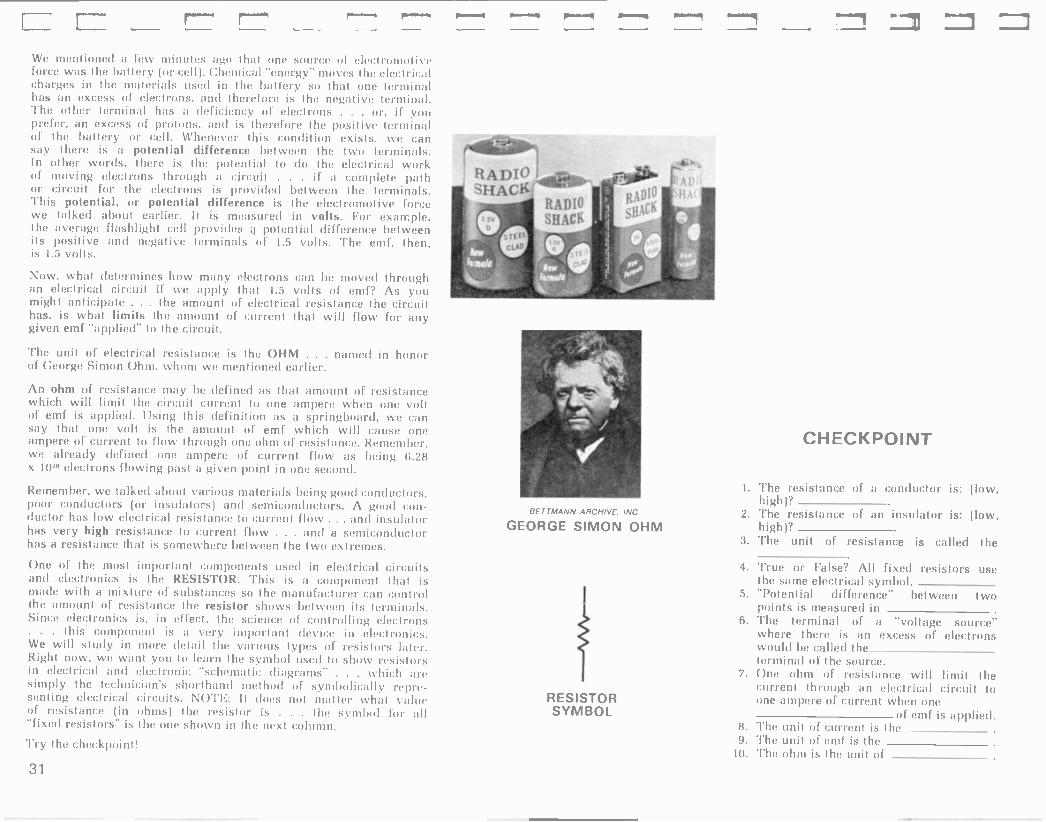
uwn¡oa ixau ay) u! uMoys auo ayo s! ,sJOIs!saJ pax!J Ile JoJ iuyutds ay) st .iois!saJ ay) (swyo u!) a:lueistsa.t Jo anien IeyM Jallew IOU saOp 11 ::1.LON sl!naJ!:l lea!Jlaa¡a lu!)uas -a.tdaJ dlie:lyoywds Jo poyiaut pueyiJoys s,ue!aiuy:tal ato rfldw!s aJe yutlyM . ,sw.tlet ep atieutayas a!uoJlulaia putt lea!Jlaata u! sJols!sa.t n1ntS 01 pasn 1ogwAs alp weal oI nod )UeM aM 'Mou Iyl!H Jaltrl sJois!sa.i jo saddo snotJen ay) itelap wow ut dpnls II!M aM s:nuoJl:lala u! a:ltnap )ueiJoduy riJan e st luauodwoa styl suOAl:laia liu!¡loJluoa JO atlual;ls ay) 'InaJJa u! 'st sowoJiaala aaulS sieultuJal sI! uaaMiag smogs Jo)slsaJ ay) aauels!saJ Jo iunowe ay) [odium ue:t .ta.tnlaelnueut ay) os saauelsgns Jo aJnix!w e 41!M apeut st ley) ivauodtuoa e st siyL '210.LSIS31I ay) s! s;ltuoJiaa¡a pue sl!naJia leal.tioa¡a u! pasn s)uauoduwa iuelaod(u! !sow ay) Jo auo
sawaJixa cm) ay) uaaMiaq arayMawos st ley) anueis!saJ e sey Joianpuoa!was e pue Moli IUaJJna 01 aauels!saJ yl!y dJaA sey JOlelnsu! putt moll IuaJJna 01 aaue)s!saJ ltt:)!Jlaaia Mol sey Joianp -uoJ pool y sJoianpuoa!was pue (sJo)einSUt Jo) sJOlanpuO:l Jood sJol:lpuoa pool lutay sie!Ja1ew snotJen wage pal¡lel aM 'Ja(lwawaH
puoaas auo u! lUlod uantl e ised lulMoiJ suoJlaala x l379 lu!atl se Moil IuaJrna Jo aJadwe auo paulJap /fpea.t¡e aM 'Jaytu Ni awaH aaus!saJ jo w ¡J yo auo ylnoJy) Mo ol luaJJnJ Jo aJade auo asnea i¡!M yOlyM Jwa JO Iwlowe ay1 s! lion auo !et]) des uea aM 'pJe.oylutJds e se uotllu!Jap s!t) lu!srJ pa!¡dde s! Jwa Jo Ilon aun uayM aJadwe auo oI )uaJJna IlnnJ!a ay) 1!ut!¡ ¡¡!M ya!yM aauels!saJ JO lunowe Iey1 se pau!iap ay deut aauels!saJ Jo wyo uy
JallJea pauolluaw aM utoyM 'wyo uowlS alroaO Jo Jouoy u! paweu N11-10 ayI s! aauels!saJ leUtJiUaia JO pun au,
otnaJla ay) ol palidde Jwa uantl due JoJ '`^OLI [pm ley) IuaJJna Jo Iunowe ay) spat!' leyM s! 'sey ltn:lJl:l ay! aaueis!sa.t ieU!Jloaia Jo iunowe ay) aled!allue iyltw nod st/ iJwa Jo swan 9-1 ley) dldde a.w J! I!nuJ!n iea!Jlaaia ue ylnoJyi panow aq uea suoJiaaia ÁUew Moy sau!wJalap ¡KIM 'MoN
SI¡OA S'I SI 'oat)) 'Jura ayJ s)ioA 5I Jo s¡eulutral anllelau pue aA!)!sod sI! uaaMiag aauaJaJJlp ¡e!Iualod é sapinoJd ¡iaa Iyl!¡yselJ aleJane ay) 'a¡dwexa .toy slion u! paJnseaw SI i¡ Jat¡.tea InOyP, pallle) aM aa.toJ aA!)owoJiaa¡a ayi s! aauaJaJJip lelivalod JO 'ie!)ua)od sly,L sieulut.tal ay) uaaMiag paP!noJd s! suoJlaala ay) JoJ pinup Jo toed a)aidwoa e J! i!na.t!:l tt ylnoJyl suoJlaala lu!now Jo l¡JOM ¡ea!Jlla¡a ay1 op oI le!)ualod ay) s! arayi 'SpJOM .r,ty)o ui sleu!wJal aM) 1141 uaaMlay aaualaJJ!p ¡e!)ua)od e st aray) des uea aM 'sls!xa uot)!puoa sp.)) JanauayM Ilaa JO dJalle(1 ay) Jo leulwJa) an!I!sod ay) arolarayl s! putt 'suoloJd Jo ssaaxa ue 'JaJaJd nod J! 'Jo suoJiaa¡a JO daual:ltJap e sey Ir.u!wJal into ay j, -leulwra) antielaEl ay) st aJoiaJayl pue 'suo.tl:taia JO ssaaxa ue sey ¡eutwJal auo ley) os ÁJalle(l ay1 ut pasn siet.taletu ay1 u! salreya ¡r.a!J):la¡a ay) SaAOw ,dl.taua le:llway3 (l¡a:t Jo) draIley ay) SUM aaJoJ an!)owoJiaaia Jo aJJnos auo lug) ole sainwtu ma] e pauotluaw am
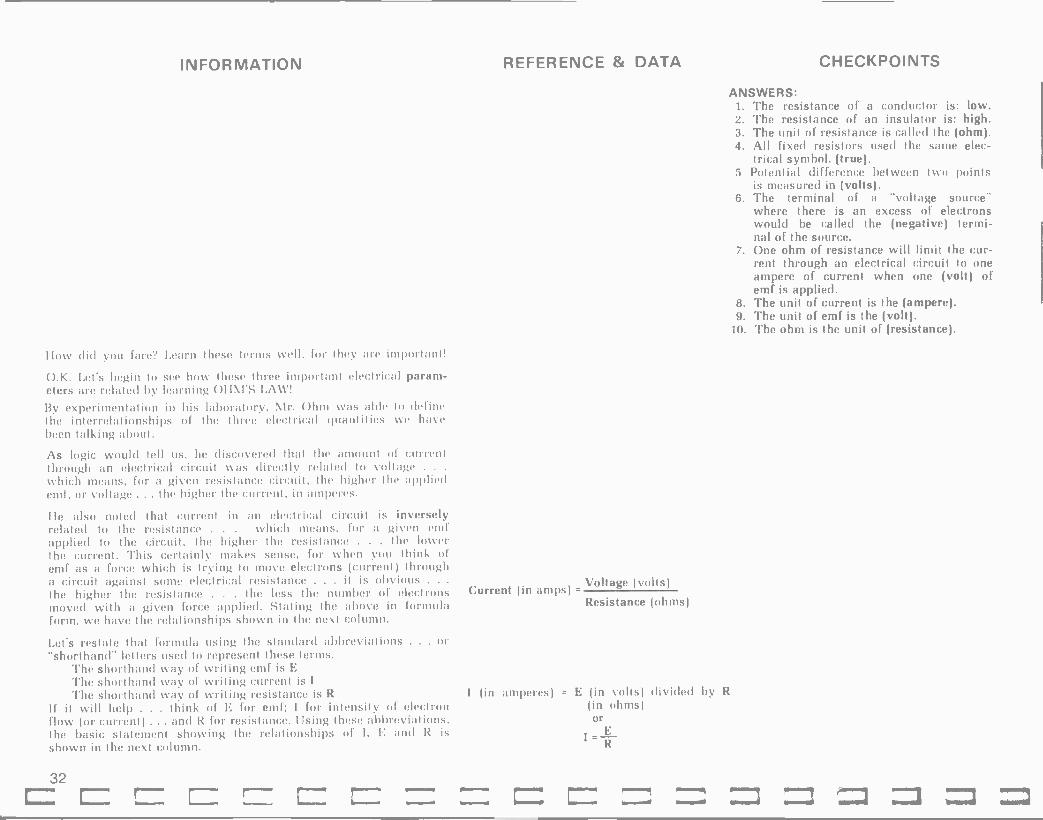
INFORMATION REFERENCE & DATA CHECKPOINTS
How did you fare? (.earn these terms well, for Ihey are important!
O.K. Let's begin to see how these three important electrical param- eters are related by learning OilTS LAW!
By experimentation in his laboratory, hlr. Ohm was able to define the interrelationships of the three electrical quantities we have been talking about.
As logic would tell us, he discovered that the amount of current through an electrical circuit was directly related to voltage . .
which means, for a given resistance circuit, the higher the applied emf, or voltage ... the higher the current, in amperes.
He also noted that current in an electrical circuit is inversely related to the resistance . . . which means, for a given emf applied to the circuit, the higher the resistance . . . the lower the current. This certainly makes sense, for when you think of emf as a force which is trying to move electrons (current) through a circuit against some electrical resistance . . . it is obvious . . .
the higher the resistance . . . the less the number of electrons Current (in amps)
moved with a given force applied. Stating the above in formula form, we have the relationships shown in the next column.
Let's restate that formula using the standard abbreviations . . . or "shorthand" letters used to represent these terms.
The shorthand way of writing emf is E
The short hand way of 1vriting current is I
The shorthand way of writing resistance is R I (in amperes) = E (in volts) divided by R
If it will help . . . think of E for emf; I for intensity of electron (in ohms) flow (or current) ... and R for resistance. Using these abbreviations, or the basic statement showing the relationships of I, E and R is E
shown in the next column. I R
Voltage (volts)
Resistance (ohms)
ANSWERS: 1. The resistance of a conductor is: low. 2. The resistance of an insulator is: high. 3. The unit of resistance is called the (ohm). 4. All fixed resistors used the same elec-
trical symbol. (true). 5 Potential difference between two points
is measured in (volts). 6. The terminal of a "voltage source"
where there is an excess of electrons would be called the (negative) termi- nal of the source.
7. One ohm of resistance will limit the cur- rent through an electrical circuit to one ampere of current when one (volt) of emf is applied.
8. The unit of current is the (ampere). 9. The unit of emf is the (volt).
10. The ohm is the unit of (resistance).
32

stu4o (££££) = a3ueslsaN £ sllon (0Z) = a8ellon 'Z
saJadwe (90) = IuaJJn3 1 :SM3MSNb'
sw4u = a3uels!saN ¿a3uelslsaJ Iln3.1l3 a4i s! Ie4M
SODA 01 Si aliellon paildde alp ua4n1 salad -we £ si iln:)J!3 e 411noJ41 Iua.IJn:) ay! JI '£
sllon = aIe1lon ¿Juls!saJ ayl ss0J3e
aáiellon a4p s! Ie4M saiadwe Z s! JopslsaJ win) 01 e glino.l4p IwaJJ03 a41 JI
sa.ladunt - = IuaJJnD 1IU8JJt13 Iln3Jl3 ay! aq !pm iegA1
sun() q Jo a3uelslsaJ e pue aleilon palldde sllon g Z se4 Iln3J!3 le3!Jl:)ala ue JI
INIOdN133H3
3
aaadwe I = I
sw4o 0Z
no7
-= 1
3
sa.tadule Z = 1
sesgo 01 =
AOZ
N =1
3
aJadwel=l swyo 01
Mil
N =1 3
££
¿up -101.10j ,11e1 s,w40 IU'IJo(lul! a41 1101 till ;331 1:10.1(1 nnri lal DI a.lay Iulodn3ag3 e wog!' moil
op leg 11 awls ria41 rig.vt ol sr. ..uuilnu rililioJ e liUlne4 Ino41tM selnulJoJ aziJOur,)w Áa.md ol well a0.11 elnulJoJ a41 anew imp sida3uo3 oyl puels.tapun nori 1041 lUr.l.lu(Itu! a.totu .nrJ s! I! .1a.1a.11o4 uteYe ries sp.! r.gng 43InJ:) )lll!I ripuell '(I rig papl.l!p s! ;I Jo) 1.lano st 3 loll aiou ... N pulJ
'(N rig pap!n!p ,I .to) 21 .1an0 l s,11 lint a10u uagp I Jo.) anlos 01 luenl I.II 'N x I pea.: ril(luns 3 J01 a.11os ol lue,vt I JI :alciwexa
tua41 gum op ol 1011m Hal unlp Jag!!! all Jo uo!Ilsod le3lsrigd agl ..1nJ ltui.11ns a.te nori riillut:nb a41 Jano3 nuñ J! 1eti1 a3!IoN
uun1103 ixau alI u! uMoys ..43In.13 a41 ripnis sw.)oJ aa.141 asagl JalwawaJ nori diay o,l, I/3 =N I)Ue N x I = Ua41 -.N/3 = I 1! leg' uAAO4s aq Uea 11
asn rilluanba.lJ IIlA1 nori g3!gM me.] s,w4O Jo su1JOJ .)alto um' a41 nori Mogs s.Ial = I Jo elnwJuJ :)!seg stgi woJ3
pat'011UaUl am dlgsUoll'1aJ as.lanut all s! sly,l, panle4 I pal(wop N st/ dine L ol (y Jn sduns paielnaJqqt:) sa..)dtue 7, tom] paseaJ3ap IuaJ.ln3 ayI swgo I1Z oI N pasea.l:)u! aM 1.104n1 silon OZ JO Ittla u' gum 1041 atON
Unelte utunlo3 pu7, agi 0! now! ¿1uaJJn3 ol suadclt:4 legnl . a:)uels!sa.l a41 alqnop pig (n) sllun 07, Ie aft o/ au' daan aM nap asoddns n1oN
axellon of leuollJudo.ld ri113aJlp s! lua.lJn3 Iegl liulnlogs IuaJJn3 alp palgnop a;iello^ a41 WUl19t1O(1 iaaS
Uutt11o3 Ixau agI u! sdals a4p Mollol u!elid ¿ase3 s141 J0J Iua.1.013 !NI aq pinonl IegM . Iln3.1!:) a41 u! a:uteislsa.) agp aliue43 loll pH) Intl 'aWellun ay' palgnop am asoddns s,Ial MoN
uumin3 plat' ali u! sdals alp nlollo;l ¿tuaJ.t'13 11n3.1!3 agi aq pinoM Ie4na . . sw4o 01, a.laM N pue stlon 01 aJaM 3 JI 'a11J1 s! sl41 '1nu1JuJ agI u! sanlen awos alnllltslns aM J! 'aldtuexa Jai aas ue3 no,k '(N) a3u0ls!sa.1 op palela.l rilasJanu! pue (3) alicllun 01 palelaJ ril133.1!1) seM (1) puaJ.033 10111 Jall.tea pl's am utelin elnutJ.l leutliuo Jnt' I' nnol sw.lol oM1 Ja4lo agI nori wogs am aJoJag
salllluenh le3lJl3ala asagl Jo sdlgs ullela.l ;Ili I puels.lapun 0I nori ILIUM ri1d110s 1n(I .1.10! !dal) dais -rig -claps au' uleldxa op aJa4 awlI a101 I.u0n1 aM U.''31 pue (INü.LSN3(1NI1 0I lu'l.tudul! rillenba a.te t1314.1n 5111J01 .10410 0A1 an!Jap ue3 !),w elnwJui a!s'd slyl woJ3
¡Ham 1! 0.1001 os anuepJodui! snopuawa.11 JO s! elntuJnJ slg.L

INFORMATION
O.K. You've used all three forms of the Ohm's Law formula now ... but we want you to begin learning how to apply this knowledge in a practical way by giving you some problems using circuit "schematic diagrams" to convey information to you.
Before we do that, however, let's talk for just a minute about what "instruments" are used to measure the three important electri- cal parameters we've been discussing. The instruments used are
really quite obvious: To measure emf in volts use a voltmeter. For our purposes we will use the following symbol to represent a voltmeter "schematically":
To measure current in amperes, use an ammeter. For our purposes. we will use the following symbol to represent an ammeter "schematically":
Incidentally . . . many times we will be dealing in thousandths of an ampere rather than amperes. As we mentioned earlier . . .
the metric "prefix" for one thousandth of a unit is "milli". Therefore. we use the term milliampere to indicate one thousandth of an
ampere ... and we abbreviate this mA.
The symbol we'll use to show a millammeter ín a schematic diagram is:
To measure resistance, an ohmmeter is used. We'll use the symbol:
While we're on the subject of resistance and ohms . . . we should point out that in many electronic circuits, we'll be dealing with thousands of ohms, and sometimes millions of ohms; and, again, you will find the metric prefixes come in handy. Remember that the term kilo means 1000. Our earlier example was that a kilometer is 1000 meters. Therefore, a kilohm is 1000 ohms. The common letter symbol, or abbreviation for kilo is K. 'Thus, if I am talking about a resistor which has 10,000 ohms of resistance, it would be general practice to say a 10K ohm resistor. For designating millions, we use the prefix Mega. Hence, a 10 Meg (we leave off the
a) resistor has 10 million ohms of resistance.
Now, let's get "down to brass tacks" in becoming familiar with schematic diagrams and using Ohm's Law to analyze these. circuits.
Initially, let's define a circuit as being a voltage source and a
complete path for electron flow from one terminal of the source to the other. Observe the diagram in the next column.
REFERENCE & DATA CHECKPOINTS
NOTE: The Greek letter omega, 11, is often used to symbolize the word ohm (or ohms).
BATTERY
RESISTOR
AMMETER
Zz1

5E 2íXI=3'E
=3 'Z 3 3
= I 'L 3
:Sa3MSNd =3
¿Mellon ilna.;la ay' Jai amos al asn noif p(noM elnwJoJ ieyM 'IlnaJla e Jai uMoun aJe sanlen aauelslsaJ pue ivalJna ay' JI
=21 ¿aouelslsaJ IlnaJla ayi JoJ amos o' asn no& pinoM elnucJoJ IeyM 'Imalla e Jai uMoun a!e sane IuaJJna pue Melton ayi JI
=1 ¿ivaJJna ay' JoJ amos oi asn nof
pinoM elnwloJ IeyM 'uMoui a!e ilnuJ!o e Jai sanlen aUellon pue aaue'slsaJ ayi Ji
INIOdNO3HO
'Z
L
saJadwe (sg) = IualJna :!l3MSNt!
saJadwe = ivaJJn3 ¿pea! Jalawwe ayi IIIM IeyM
1NIOdD1O3HO
T 1-
1- T+
n5Z
E uwnlo ul iulodYlaaya ayi ala(dwoa 'elnwJoJ Mei s,wyo ail' Jo SwJOJ aalyl Ile puelsJapun noR JI aas o, iiy8IJ IIV
luaJJou ay pinoM noÁ (saJadweilllw) duc sZ paJaMsue noif JI ¿aq ivaJJna ay' pinoM IOWA uayi suyo 01 Jo peaisul strum mot seM aaue'slsaJ atp imp SulsoddnS
uwn(oa pJlyi ayi ul 'ulodhlaaya ay' ti! Jai panse slaiaweled lump agi Jai amos 'Mey s,wyo Iulsn ifq pue 'uwnloa ixau ayl ul aliewayas ayi je looi
ipnls sselJ It'JauaD pue uelaiuyaa,L ayi al Ial-3 uayM sweJfleip allewayas inoge aJow weal II,aM
aJoJaq ilIIeIJu'ald uMoys ilnaJla ayi aiiewayas Jno s,aJaH
sleulwJai Jo 'sapoJiaala anlilsod ayi saw! JaWuul ayI !sleuluwai anlielau sllaa yaea IuasaJdaJ saw 'Joys ayi aI image ÁJaiieg ayi Jo.; anli sl awes aya, leulwlai aniiisod ayi aull la1uol ay' pue Ilaa atl' Jo IeulwJal anlielau ayi s'uasaJdaJ logwÁs alp u! au!! iJoys ay' imp anJasgo asea(d
:s! Ilan a(dwls e Jai logwifs ayy paivauuoaJaiul ifIleuJalul sllaa mow JO am' sl klai'eg t/
:sl e Jai IogwRs ay,J, wJoJ welfleip ai'ewayas ul ilnaJla awes siyi noif Moys uayi pue 'rfJaiieg ayl JoJ loqwÁs ayi uJeal s,iay weJ8elp lelJo'ald e Jo 'Jos seM 'eyy

INFORMATION
Do you have those formulas well in mind? I hope so. You will use them the rest of your life as an Amateur or technician.
We've been speaking of moving electrons through a resistance by applying an electromotive force. As you can imagine . . . when this work is clone, heal is generated. Even though we are talking about moving things as microscopic as electrons, heal is generated. In fact, a measure of how much work has liven clone in a given unit of time is called power. Electrical power is measured in units called watts . . named in honor of the scientist who studied work, power and energy. For your purposes at this time, it is
only necessary that you learn that the amount of power dissipated by a circuit (like we've been studying) is related to the three electrical quantities-E, I and R. For the lime being, you'll only use one form of the power formulas, namely:
Try the checkpoint!
We have been dealing with some "pretty heavy" electronics funda- mentals so far in this chapter. We felt that it was important to
begin to lay the "ground -work" and give you a good "foundation" upon which to build in later chapters. Because the Novice Class License test sloes not require "in depth" electronic theory knowledge, we'll just introduce you to terms and rules and regulations which you may encounter in the Novice Class examination. In other words, we will not go into detailed explanation at this lime, but simply will familiarize you with them for "exam" purposes. Later in the
book, many of these topics will be taken up in detail.
Most all electronic circuits are made op of a combination of some,
if not all, of the following six basic electronic components: Resistors, Capacitors, Inductors, Tubes, 'I ransistors and Semiconductor Diodes.
You should learn the symbols for these, and some of their basic functions. Let's go through the list, one at a time.
The resistor is used to limit current, and in some cases to provide a desired voltage drop across itself. You have already seen pictures of resistors and the proper schematic symbol, so let's move on
to the Capacitor.
The symbol for a Capacitor is:
REFERENCE & DATA CHECKPOINTS
P (power in watts) = E x I, where E is in volts and I is in amperes.
CHECKPOINT
If a transmitter circuit has an applied voltage of 100 volts and a circuit current of 0.75 amperes . . . what is the power "input" to the stage?
P = waits.
ANSWER: P=ExI P = 100 x 0.75 P = (75) watts
36

(sqwo¡ñoO) u¡ parnseaw sr aSreyO q
:si ro11aedea e roJ ¡ogwiCs ay; pue '(pere3) ay; s¡ aaueltaedea jo pun ay,j, 1,
aSreya e jo wroJ ay u RSraua ¡eaplaaja (arols) o; s¡ rolcaedea e jo uo;aunJ ay,j, £
--- :st rolsysar e roJ ¡oqwRs ay; pue (tuyo) ay; sy a3uels¡sar jo ;iun ay,j, Z
(aSel¡on) sdorp pue luarrna sltwy rolsysar y L
:S133MSNV
parnseaw s aSreyO g
:si ro13edea ro3 ¡oqwiCs ayl pue ay1 s¡ aauelpedea 3o nun ay,j, L,
aSreya e Jo wroJ ay; uy ÁSraua ¡e3p13a¡a ol rolpedea e Jo uoyl3unJ ay,j, £
:st r01SIS -ar e roJ ayl pue
ayl Si aauelsysar Jo 1un ayL Z
sdorp pue luarrn3 slOw[¡ rols!sar V L
1NIOdN103H0
30anos Ot! 30 31dwt/X3
AO ZH 09 1N3aa(lO 3S(lOH
331lnOS 30 30 31d1AIt/X3
AO 1 J11:1311t19
ns T
uo/u11-a0O/0 /o uo¡s¡e¡p s31U0u3e/3 eql 'qe/ei/uaa /o ÁseomoO oloqd
LC
s¡euóls Od ssed pue O nao¡g o1 pasn aq usa 1 pue 'uSysap linary3 ay; ynM aaueproaae sasea¡ar pue 'KSraua yeaplaaya sarols 1! :roliaedea e 3o uoilaunJ ay1 SUfzIreWWnS `os
rayloue ol lin3rt3 e uy luiod auo worJ ssed o1 luarrna ro saSe1¡on (luarrna Suileural¡e) Od ssed ro 'Moy¡e o1 pue rayloue 01 1[n3r¡3 e uy luiod auo worJ Su111a8 worJ luarrna ro aSel¡on (luarrna 1aarp) OQ luanard ro 9¡ao¡q ol si 'ra1e' inoqe arow urea¡ noif yaynn roliaedea e jo uoilaunJ raylouy
iluiodvaya ay1 fr 1
aSreya jo (suorlaa¡a 9101. x gZg) gwo¡noa auo arols 'um pay¡dde l¡oa aun ylyM y3yM aauelaedea Jo lunowe pere3 t¡ pere3 ay1 st aauelpedea Jo liun ay,j, aauelyaedea sly raySyy aq1 'paqdde aSeljon uanyS e roJ arols uea roliaedea e aSreya arow ayj
uwn¡oa 1Xau ay1 ui srolyaedea jo yeranas 30 arnlayd ay1 aatloN roljaedea ay; SuiSreyasyp pa¡iea aSreya ay1
3o Suiuierp siy,L JJo pauyerp st a8rey3 ay1 yylun luarrn3 ro/pue aSel¡on Jo aarnos e se as usa 1! 'paSreya roliaede3 0111 03u0 'aledi3ilue uea noR sy suorlaaya Jo ifauaiaijap e 'sale¡d Jo HS JO 'aleid raylo ay1 'suorlaa¡a Jo ssa3xa ue sey rolpedea ayl Jo saleid Jo 1as ro a1e¡d auo leyl os aSreya e Suyrols Rq syyl saop ll
ÁSraua ¡e3ir13aya arols ol si roliaedea e Jo uoilaun3 ayseg ayy

INFORMATION The next component on our list is the Inductor, sometimes called a coil. The capacitor stores electrical energy in its "electric" field between plates of the capacitor. The inductor also stores energy in a field . . . but the inductor stores energy in the form of a "magnetic field", which we'll learn more about later.
Whereas the capacitor has the characteristic of "blocking" DC, and "passing" AC with little opposition . . . the inductor, or coil does just about the opposite. This means the coil allows DC to pass with little opposition, but tends to offer opposition to the passage of AC. In fact, the higher the "frequency" of the alternating current . . . the more the opposition to its passage through the inductor. You do remember our "old friend" frequency don't you? Recall that "house current" is probably at a frequency of 60 Hertz . . . and it is, of course, alternating current . . . abbreviated AC.
There are two basic types of coils that you need symbols for: namely, the "air core" type . . . a around a form with nothing but air in the middle iron -core type. Note the pictures of these in the
to know the coil wrapped
. . . and the next column.
The symbol for the air -core coil is:
The symbol for the iron -core coil is:
The unit of inductance is the henry, named in honor of another scientist.
Iron -core inductors are used in circuits which are operating at relatively low AC frequencies. For example, at power line frequency (60 Hz) up through what is called "audio" frequencies (from about 20 Hz - 20 kHz).
Air -core inductors are used at higher frequencies ... often called RF (radio frequency). Many circuits in your TV set may use these RF coils. Almost all electronic equipment requires power supplies of various sorts, where Iron -core inductors are used fre- quently. So, you see, inductors are very important electronics component.
Verify your learning by doing the checkpoint.
REFERENCE & DATA CHECKPOINTS
CHECKPOINT
1. A capacitor tends to block but to pass signals.
2. An inductor tends to allow to pass with little opposition, but to impede signals. The higher the frequency of signal, the (greater, smaller) will be the inductor's opposition to its passage.
3. The unit of capacitance is the 4. The unit of inductance is the 5. The schematic symbol for a capacitor
is:
6. The schematic symbol for an air -core inductor is:
7. The schematic symbol for an iron -core inductor is:
38

ll :51 Jolunput aJou-uoJi ue Jo] logwRs alpewaqus ayy z
:sl Jolunpui aaoa-Jie ue Jol logwRs ailewayus ay,L g
T :s1 Jolluedea e Joj logwRs ullewayus au g (Raua[{) aqi Si aaue;anpui jo nun ay,L ti
(peae3) aqi si auuelluedea jo nun au E a8essed sll ol uoilisoddo
s ao;unput ay; aq lnM (aapeaa8) aq; 1eu81s at]; jo RauanbaJj alp JaySiy ayy sleu8is (Dd) apadwl 01 lug 'uoillsoddo alllll yuM ssed op bu) Molle ol spual aolanpul uy 7
s¡eu8is by) ssed op lug '(Du) nuo¡g o; spuai Jollaedeu y i
:SFI3MSNt/
t. .
,1
6C sleu8ls apejaua8 Ray L
sleu8is Rpldute RayL sleu8ls Rnluaa Ray,L
:suoi)uunj óUuMonOj all) Jo auO W.IOpad R1)UanbaJj sagn) wnnaen 'sOIUOJ)nala ul
uwnlOu )xau ay) ui saint wnnaen awos jo aJnluld ay) )e >looq lelaw sawi)awos JO 'sse18 si aJnsoluua Sly) R11enS(i aJnSoluua pa)enaena ue u! S)uawala 1eulJ)uala S)I seq aqn) u:nnuen ay) os aJnsoluua sse18 (Jie ou) R)dwa, ue apisul )uacuellj e gum pa)unJ)suou aJe asnoy Jno/1 U! sging )y8!) ay) se )sill (aplsui Jle ou JO a1)111) aJnsoluua ,pa)enuena, ue ul aje s)uawala saqn) ay) )eyi saildwi awn wnnaen Ulja) ayj,
'OM! JO loqwRs e sdeyjad pUe ' ' RJ)InuJlu SaIUOJ)Uala UI wjopad o) pau8isse R1)uanbaJj aJe Ray) suoi)uuni lejaua8 ay) 01
noR aunpoJ)ui O) )ueM RldUlis 1ng sagn) wnnaen lo sadR) snoiJen alli 11e jo uoi)eJado jo RJoay) all) o)ui o8 o) Ja)deya sit]) ul aun) ane) o) 8u1o8 )ou ale am agnL wnnoe/r, aqi si s)uauod -woa uluo)uala uiseg xis jo )sil RJauoJB Jno uo wan )xau ayL
noR dial] o1 swJa) lo )sil MainaJ e noR ani8 lliM aM Ja)deyu sup Jo [ma ay) Jea¡v 5IJOM poo8 aqi dn daam Jej os s)Jojja JnoR uo suoi)e1n)eJBuop )sa) auino(\l ay) Joj paJedaJd 11aM 8ulaq se 1laM se 'sasuaull Jna)ewd jo sassep pauuenpe ajow Jno C pJeMo) )Je)S peay snol7uawaJ) e 8ui))a8 aje noR suma) Mau asay) 11e dn Supluid aje aje noR Jl )ulodnuayu leg! uo 11aM pip noR Ism ,L

INFORMATION
Now, what do those terms mean? For the time being, let's give you a brief definition of each function.
A rectifier changes AC voltages or currents to DC voltage or current. One example of the need for "rectification" is your radio or TV. If there weren't a rectifier and filter circuit In the power supply, you'd hear terrible 60 Hertz hum all the time. In a very simple statement ... a rectifier changes AC to DC.
To amplify means to make larger or build up. A tube used to amplify simply builds up an input signal to a larger output signal. For example, one might put in a signal to an amplifier that is only 1 volt . . . but the "amplified" output voltage could be 100 volts ... etc.
When a tube is used to generate an AC signal, it is often called an Oscillator. The tube's function here can simply be stated as changing the DC voltages into an AC signal of desired frequency-this becomes the output.
Most vacuum tubes have a filament . . . called a heater. The heater is used to heat up a tube element called the cathode. The job of the cathode is to "emit" electrons when it is heated. These electrons are then available to he "collected" by the tube's plate. The plate is the tube element which attracts the electrons which have been emitted by the cathode. The tube we have just described is called the Diode tube, because it has two active elements . . .
the cathode . . . which emits electrons, and the plate . . . which collects them. The prefix "di" means two. For example . . . when you "disect" something, you cut it into two parts.
Look at the schematic symbol for the tube we have described is in the next column.
We've mentioned several functions of vacuum tubes as being rectifi- cation, amplification and their use as oscillators. The diode tube we just discussed often finds application as a rectifier. We will discuss how this is accomplished later in the book.
A tremendous "giant -step" forward was made in the world of electronics when Dr. Lee DeForest introduced a third major element in the vacuum tube. This element was physically placed between the cathode and the plate, and this third element was called the control -grid. Instead of being a solid piece of metal, such as the cathode or plate, the control grid has evolved to be a thin "spiral" of wire.
Because the tube now had three active elements, it became known as the -Triode -tube. The prefix-tri-means 3. Many examples of this prefix being used to designate 3 are available, but perhaps a very common one would be the common toy the "tricycle", which has three wheels.
REFERENCE & DATA CHECKPOINTS
PLATE
HEATER] IICATHODE
DIODE TUBE
. . .
, .
Dr. Lee DeForest
40

3a0Hltl3I I I2131d3H
31vidi
z sJawinag j Sli3MSNtf
¿aqni wnnnen e ui aieid ayi jo uoninunj ayi si leyM g
¿aqnl wnnnen apoiJi e ui p!JS -OJiUOn ayi jo uo!inunj niseg ayi si ieyM L
¿aqni wnnnen e ui apoyien ayi jo uoiinunj niseq ayi si leyM g
sivawaia alp lie ¡aye! pue apoiJi aqni-wnnnen e Jo.; iogwRs ayi rweJp
¿aney apo -!Ji e saop sivawala amine /Cuew MOH
aqni y ¿JaWldwe ue se pasn uaiio s; agni jo adrCi leyM £
sluawala laqey Jaieay ayi apninui apoup aqnl-wnnnen e Joj logwrCs ay; ,tieJa Z
se pasn uaijo ale sapoiQ ¿aney ualjo agn; apow ay' saop uoiien!idde niuoJinaia ieyM
INIOdN33H3 i
108WJ1S 3an1 3aOl1:11
3a0Hlv'3II 11131V3H
1t113141 a0 ssd-10 13d0-13AN3 38n1
31b'id
al2ia -10211N00
Lti
sinej pue swaal nnau asayi jo awos pauJeal an,noÁ J! aas oi iuiodynayn e Jo.; asned
Jawidwe ay; olui leu8is ayi uey; (asnn -luaJJnn Jo aciellon) apni!idwe UI JaleaJ`Ó saw!' ÁUeW SI ieu8IS ay; saWeis Jo abeis Jawidwe ay; jo indino ay; le ley; sueaw Áidwis leuxis e jo uoneawidwy uogenundwe algissod apew MOU py8 !tuition ayi jo uoi;ippe ayd, saqni apoiJi pue apoup ayi ui pasn saidinu!Jd a!seq ay; wo.y aleaado saqn; wnnnen niuoJinala Ile ÁlieniJin
'p!JB JoJiuon tun; ay; anuay aleld ayi yneaJ ;pm suoJinaia ayi jo ,Sew nnoy 404UO3 uen p!JS oJiuon ay iwayl sinallon aleid ay; pue 'suoJinaia si!wa apoyien ay; 'JaqwawaN ;y8;J ay; le unnoys si aqn; apop,j. ayi Joj logwÁs ayd,

INFORMATION
You may have noticed that we have changed our style in giving the answers. This is to conserve space and allow us to give you more teaching in a given space.
Now that you have had a chance to get used to the format of the book, you can see how to easily refer hack to the CHECKPOINTS when checking your Answers.
In the General Class section, we will expand on the vacuum tube, and discuss some other tubes that have been derived from the basic diodes and triodes. For now, we need to move ahead and briefly mention the device which has revolutionized the electronics industry ... the transistor.
One of the tremendous advantages of the transistor is its small size. Also, because it doesn't need "heater" power, the associated circuitry is less bulky. Because of the low power requirements to operate transistors, most all the associated components have also been "miniaturized".
Transistors are frequently referred to as semiconductors, and as solid-state devices. They are called semiconductors because they are made of materials that "atomically" fall into the semiconductor category. The two most popular semiconductor materials for transis- tors are: germanium and silicon.
Both of these semiconductor materials have four "valence" electrons. (Remember our discussion of conductors, insulators, and semicon- ductors?) They are called solid-state devices because the various materials that make the active part of the transistor are all in one solid piece, as opposed to vacuum tubes, where the various elements are separated by space. etc.
For now, you should learn the symbols for the two basic types of transistors, and briefly, what is meant by "N" type material, and "P" type material.
REFERENCE & DATA
171
Transistors vs Tube (size comparison)
BASE
EMITTERO COLLECTOR
Pictorial Concept of Transistor Materials
"Sandwich" for "NPN" Transistor
3. Triode 4. Three 5.
CONTROL GRID
CHECKPOINTS
PLATE -TUBE ENVELOPE,
GLASS OR METAL
HEATER) IICATHODE
6. To emit electrons 7. To control how many of the emitted elec-
trons reach the plate. 8. To "collect" the emitted electrons.
42

am llsod 17
adAl N '£
113111013
3St19 230103-1-100
.Z (saqnl ueq alll<eJJ ssal
sluaulaalnba.l JaMod JaMoi 'azls
:S1:13MSNb'
luasaad uoJloala ue aJay1 aaaM ag pInUM II JULIAN 01 paJedwoo aSJe4o (anlllsod 'anlleSau) e Sulney se paJapisuoa aq Aeul ~lanais olwoe ue us alog d
IeiJalew Jolanpuoo -iwas adAl palleo si "'mew 041 ySnoJg anow 01 paaJJ SUOJI -oala awOS aq IIIM amp imp os paloalul uaag se4 AIIJndwl ue goiyM u! IeiJaleNl
speal Joloalloo pue 'aseg 'Jalllwa ay Iagel pue 'Joss! -sueJl adAl NdN ue JoJ IogwAs 041 MCJp Z
aqnl wnnoen a4 oI paJedwoa Jols!sueJl 041 JO saSeluenpe OMI aweN
INIOd)103H0
(aseg pJeMol sIu!od Ma aae Ja11!w3 :aloN)
loqwfg Jols!sueJ,I, dNd
(aseg won ÁeMe su!od MOJJe JaI1!w3 :OWN)
IoqwAs JOIs!sueJ,I, NdN a311IW3
3Sá9 2101031100
Jns!sueJ,I, ..dNd jo IdaOuo3 eJo4o!d
- { d N d -- 2i01331105 133111W33St18
E17
AJI e Iulod)Ioayo ails amp liuiop aJ,noA Moy aas saq
sle!Jaleul d pue N Jo eapl alp pue slogwAs asp weal 'Mou 10,4 J01911I103 OUR aseq 'Jaiwa :suawala JolslsueJl ay] JO umlounJ aql Ino4e aJow Jadego IeJauaD asp ui JaeI Apns sum no),
uollen!s sop Jo.; aweu alp aweaag IelJalew adAl-d aaua4 (antis aJaM SuoJloala ayl p aq pinoM Aay1 Ie4,w nl paJr.dulno) paSJr.yo Alanlllsod paJaplsuoo ale SUI)Ioel aae suOJloala aJaqM salmq, Jo sa)Iaod asa4y Sul)Iael aae suoJoala aaa4M studs awns ane4 01 IelJalew al1sodwoa alp sasnea 4314M '(£ 'Alaweu) wow q:)ea L! suuJl:mla aoualen b Loup Ssal Sulney Jo 3IISIJ111oeJeqo 1141 seq golyM paleJSalul uaaq Sey .,IeiJalew AIIJnd -wl Ih.loads 4oIq,H 01u! Ie!Jalew Jolonpuoolwas sl IelJalew adifl d
IelJaew slit JoJ padope seM adRl-N u1JaI a41 'anlleSau aae suoJloala aouls sunJloala anow-os-aaJJ Alan!IelaJ awns ane4 U I! asnl:o IIIM golgM Ie1J01ew ApJndwl leloads, awns paonpoJlul Alasod.lnd se4 Jaanl:ntJnueul 0y1 4o14M ui IelJaeu1 Jolanpuuolwas sl adAl N'11114sinu e Li! 'IIaM 'IelJalew adA d I)UI? IelJalew adAl N Ág UeOLII am op planM a41 UI IP.LIM 'MON
slelJalew adAi cl = Joloalloa pue :adA1 N aseq tadAl d Jallswa a! 1e41 'uolleJnS!Juuo allsoddo ay1 gIIM JOISISUeJI e ol JaJaJ mom dNd 'Ie!Jalew adAl N sl Joloalloa 041 pue IelJalew adAl d sl aseg a41 IelJalew adAl N sl Jalllwa ag1 sueaw Aldwys NdN sJolslsueJl dNd 041 puY NdN 091 Jo] slogwAs a41 a1oN

INFORMATION
Two other transistor terms you ought to know (but don't need to know the "theory"): Alpha and Beta. Transistors have the capability of amplification, as many tubes do. These terms Alpha and Beta are used to indicate the amount of "gain" a transistor has. Alpha is simply the comparison of the "collector" current to the "emitter" current. The value of alpha for most transistors ranges between 0.95 and 0.99.
Beta, on the other hand, is the relationship of the collector current to the base current. The value of beta for transistors can range from 10 or 20 up to many hundreds. Beta is a very meaningful term for the design engineer, and is term that you ought to at least have heard.
Checkpoint!
REFERENCE & DATA CHECKPOINTS
While we are on the subject of semiconductors, we should mention that semiconductor diodes have replaced many vacuum tube diodes in application. Just as you learned the symbol for the plate of the tube (collector of electrons emitted by the cathode), and the cathode (emitter of electrons), you should learn the symbol for the semiconductor diode. The anode does the same job for this diode that the plate does in the tube . . . and the cathode basically
CATHODE ANODE performs the function of the cathode in the vacuum tube diode. Diodes, either semiconductor, or tube, perform quite a number of useful electronic functions. We've already mentioned rectification (changing alternating current to direct current). Diodes also are used in receivers as detectors. You've heard the term AM radio. This refers to the method whereby the "intelligence" (sound) is put on the transmitted radio signal. A detector is often called a "demodulator", because the detector circuit (diode and several associated filter components) recovers the audio intelligence from the complex "modulated RF" signal, and sends this audio signal on to the audio amplifier circuitry in the receiver (to be built up to a level to drive a speaker or earphones).
Another function that diodes are sometimes used for is to help "modulate" an RF wave . . . in other words . . . as a "modulator". Just learn the term for now.
Still other functions are electronic switching and limiting or clipping. (Limiting the amplitude of a signal . . . or clipping off part of the signal).
SEMICONDUCTOR DIODE
CHECKPOINT
1. The ratio of collector current to emitter current is called the transistor's
2. The ratio of the collector current to the base current is called the transistor's
ANSWERS:
1. Alpha 2. Beta
44

17 pase!q as.ranag
gloowg pau!Ijapun
uaaq aneg pinogs jal!w!I pue `ao'elnpow 'ao'e!npowap 'jolaalap 'jaddlp 'aa!J!loaa
~sod
300NV OOH1dO
e Z
L
:Sa3MSNV
(?J HDIH) ¿pase!g asaanaj
JO pjeMjoJ Molaq uMogs apo!p aqi sI
indino s1! le 3 (álulfeslnd 'y wows) ap!nojd o' s! aall!J Rlddns jaMod e Jo asodand a41,
jal!w!I 'ao'elnpow 'Joselnpow ap 'aoloalap 'aadd!p 'aa!J!Idwe 'aarJrlaaj
:pas!) ag Rew apo!p aqi ga!gM u! Molaq pals!I suu!InunJ aqi au!Iaapun
apoglea aqi ueyl (an!1eWau 'an!l!sod) wow aq ssnw apoue aq1 ',.lanpuoa of apo!p ag' joJ japao uI
'E
Z
apoqlea pue apoue aqi Iagel pue 'apolp jofonpuoa!was e joJ IoywRs aqi Mea L
1NIOdNO3H3
(Riddns jannod aqi pa((eo uaw))
IA13.LSAS 2I3.L113-a313I.LO3a O--
indino 0--
a 3 1 1
3
1 3 3 a
OO 30 H100WS 9NIlVSInd
3V
31:I0111 a3SV18-3S?I3A32I
(a HOIH)
31:IOICI 3SVIH-CRIVM2103 Aa311d8
+ I
24313W 1N3112100
Mo13 1N3aa03 NOa10313
a01SIS3a (a MO -1) 0NIl1INI-1 1N3aaf13 30010
2u!op aj,noR Moy aas pue 'lu!od)laaga aagloue joJ asned aallag Ram
31a 'sjolelllaso 'sjalJ!Idwe se gons sl!nua!o a!uojlaala aqs paaJ ol 3 yloows s! uagl I!najla aali!J agl Jo lndinu ay1 pue saw!f aie!adoadde aqi le Ráijaua Ieajlaala pajois Su!sealaj Áq 3p 8u!leslnd ay1 jo sRallen aqi u! IIlJ uaqi sluauodwo3 ?I3.LZId aqu, .3Q Uu!'eslnd o' au!I aannod aqi wojJ aSellon 3V ails S u!3uet'3 yo qol aqi wjoJaad (s)apo!p aqi ssuajana pue saáelion álu!'ejado 3 awos aa!nbaj sl!naa!u oruojlaala 'sow awns sfnaa!a Rlddns aannod u! Si sjolanpu! jo/pue 'sjoilnedea 'sjo's!saj ql!M pau!qwoo sapolp jo uo!1ea!Idde injasn Rjan auo '! aoJ pallea l!naj!a ay' uayM 1! asealaj pue 'RSjaua ajo's pinoa saolonpu! pue sjol!oedea Ieyl pauolluaw aM jarljea ieqi IleaaH
pase!q-asjanaj s! It Res aM 'uo!lanpuoauou Jo uo!'!puoa e u! Si apo!p aqi uagM pase!q-pjeMjoJ s! '! Res aM Surlanpuoa Jo uo!I!puoa e ui sr apolp aqi uagM
apoqfeo ay1 0l 'aadsaa y1rM anrl!sod Iou s! apoue aqi uagM (a3uels!saJ yx!g Rjan e set' ao 1! y:3noagl ssed 01 manna MoIIe I,uoM) fanpuoa I,uoM pue 'apoglea aqi o1 laadsaa gl!M an!s!sod s! apoue aqi uaqM (1! yInoat'i mot.; fuajjna o' aauels!saj MoI e set') lanpuoa II!M apo!p ay1 1ey1 1neJ aqi wojJ pan!aap aje suorlaunJ asayl 11V

INFORMATION
O.K., let's move on to some other terms that might appear on the FCC test. It is not neccessary at this time to know all the detailed theory for each term, but you should be aware of the basic concepts of each term.
In Amateur Radio and in Commercial Radio, many transmitters have stages referred to as frequency multipliers . . . or simply multipliers. The function of a multiplier stage is to produce some multiple of the input signal frequency at its output. (See the illustra- tion). In a practical sense, multipliers may produce useable output at 2, 3, or 4 times the input signal frequency. Efficiency factors prevent a single stage of "multiplication of frequency" to go much above 4 times. If more multiplication is needed, the output of one multiplier stage is fed to another multiplier stage as required. Incidentally, a multiple of any given frequency is called a harmonic. ri' For example, the 2nd harmonic of 100 Hz is 200 Hz; the 4th harmonic of 300 Hz is 1200 Hz ... and so on.
REFERENCE & DATA CHECKPOINTS
Another term related to transmitters is parasitics. You are probably familiar with the word parasite ... referring to the animal kingdom. Generally, this refers to something attached to "whatever" and drains off part of the resources of the main object to sustain itself. In the transmitter . . . a parasitic oscillation is one which is not at the desired frequency . . . and is often far removed in frequency. To sustain this "undesired" parasitic . . . some of the stage's useful energy is used.
Still another transmitter term is the word overmodulation.
Think back a little and you will remember that we mentioned the term modulation. Transmitters accomplish the feat of putting the audio "intelligence" on the transmitted wave by one of several methods. AM signals are those using Amplitude changes for doing this . . . hence, AM = Amplitude Modulation. 1'M signals use either frequency changes or phase changes to perform this function. In any case, overmodulation refers to a transmitter signal in which the audio signal modulates the radio frequency signal MORE THAN 100%. When this happens ... "spurious" (unwanted) new frequencies are generated . . . and the FCC frowns on this.
While on the subject of transmitters, let's quickly discuss what A-1 transmission means. This is the type transmission you will be using as a Novice Class operator. In essence ... it is "amplitude - modulated telegraphy" without use of audio . . . in other words "on -off" keying of an RF carrier. The "A" shows that it is Amplitude modulation; whereas the 1 inciates telegraphy by "on -off" keying.
Another term you might see, which is related to keying, is the term key -click filter. The purpose of the key -click filter is to reduce radiation of undesired, or spurious frequencies, which can be caused when the RF signal is turned "on and off" abruptly. The filler, in essence, smooths the beginning and ending of each "pulse" to reduce this effect.
46
INPUT
INPUT
01
FREQUENCY MULTIPLIER
MULTIPLIER
V V
OUTPUT r rl.11l-VV
-11111111111
MULTIPLIER
OUTPUT
RF BURSTS (Keyed RF) WITHOUT KEY CLICK FILTER
i
KEYED RF WITH FILTERING

2.17
.L '0L (dpls saiqeu3) d g
(s/aSels AH ow! olpne sijasul) 3 (sJalilwsueJi ul pasf1) 3 z
,apoo salidw[ fqdeJSalai-sieuS!s aolon jo uolsslwsueJi 01 sjaJaJ auoydalai,o!peH
(ÁydeJSalalotpeJ sueaw L -H) .4 '9 (wall
aanpaJ !seal' le 01 Jo sapuanbaJJ snoljnds luanaJd oi AH JaiilJ oi pase) dS
.L (sleuSls paJlsJapue) d '6
(zH 0S6 = OSI x E = oluowaeH pJE) , 3 Z L L
:SH3MSNV
SJeaA I L s! apila lods-uns au, 'OL
dpls sluanajd anent-Als y 6
DU 013y saSueqo Jolelnpow y sJanlaoaJ
Jnalewe u! Alu!ew pasn s! Joielnpow y suolsslwsueJl
auoqdalalolpeJ oI sjaJaJ uolsslwsueJ! I -V
Asap s,JoieJado o!peJ ato le Aan ay! Jo punos ayl lalnb oi pasn s! JalllJ 13!(o-Aan y
NOIltl1S NOIIVIS JNIAI30323 JNIllIWSNt12il
G 3ONb'1SIa dINS
9 3ndM ANS
S
%00L uegl wow paielnpow Suiaq s! leuSis AH aqi !et!! ueaw aM 'Su!JJnnao s! uollelnpowJano Iegi 'Jo paielnpow -Jano s! Jall!wsueJi e leg! Á e aM uagM ti
saSeis JalllwsueJl u!elJao ui paleJauaS aJe qo!qM sa!ouanbaJJ paJ!sap aje so!i!seJed £
'H OOE s! zH 091 JO o!uowJeq pJ!yl aq,i, 'Z
saw!! ala 'thZ 'zhl 01 !ou pue ÁnuanbaJJ Ind -u! SI! Jo aluowjeq awos 01 salouanbaJJ Ald!ilnw Aluo uea sjaild!llnin) AauanbaJA L
asleJ JoJ .4 pue anJ! Huy JaMsuy
1NIOd)103H0
\
323HdSONOI
21o.Ld7I1UOIN 3H.L 3O NOI.L3Nf13 JNIMOHS
213.L.LIWSNdH.L WH 7d3Id.[.L V
VNN3INV
aolvnnaow
dWV da
1VNId
39V1S a31Vina0W
'dWV H333dS TU
jne _I áo
lu!odnoaqo lsel aqi aouis AJoi!JJaI jo l!q e a!!nb paJanoo an aM aou!s 'iu!odyloago asle;l -anJ,L,, e noA an!S pue `sainulw jo aldnoo e JoJ asned Jailag Ram
sJnoq Jo salnulw MaJ e I(e ie w!q Jeag o! ame aq Iou uag! pue auni auo le ÁlJealo Jnaiewe olpeJ e SuiJeaq aq 01 alg!ssod s! I! AyM su!eldxa slq,i, aloño lods-uns JeaA IL agi 01 uolle(aJ u! pue Aep o1 lgS!u woJJ AJen ajaydsouo! aqi jo suo!l!puoa aq,I, dpls palleo sawilaulos s! siqI, u!S!Jo Jo !ulod si! woJJ aouels!p Suol e pan!aaaJ Swag pue glJea !memo! >loeq ivag Sulag uagl 'suaneag alp pJeMol alSue ue le Sullanej! 'u!S!Jo jo !ulod ay! Sulneal leuS!s pa!!lwsueJl aqi Su!Mogs aJnBIJ aqi a!o¡v ajaidsouo! alp paileo aoecls paz!uo! Jo JaAel e Áq giJea pJeMo! )loeq ivaq aje galgM sleuS!s o!peJ a.le saneM-AnS suo!sslwsueJl aouels!p-81101 JoJ apow aneM-Ans aqi uodn puadap spueq o!peH Jnalewy aq! u! suolss!wsueJl !sow !ep uo!luaw lgS!w aM 'sJalllwsueJl Jo ioalgns ay! uo al!gM
aleJ o!pne ay! le AN aqi jo aseqd ail Jo AouanbaJJ alp SulAJen /IC] JO taleJ owe aql le IeuS!s .H ay! Jo apn!lldwe ay! SULAJen Áq uo!lounJ s!gl wjoJJad ueo Joielnpoul aq,i leuS!s algelllwsueJ! al!sodwo3 auo wjol aouaSillalu! aq! pue dH ay' legi os saSeis ,4H-palelnpow ale!JdoJdde aqi ow! aouaSiilalu! olpne aqi slnd qolllM JalIlwSUeJ) e Jo aSeis aq! s! Jolelnpow ayL Jolelnpow s!
Moul pinogs nuA ley! sJalllwsueJl o1 pap -lad wja! Jayloue II!!S

INFORMATION O.K., let's move on now and talk about some fairly common problems related to Amateur transmitters . . . and what precautions can be used to reduce or prevent them.
First, let's mention the term chirp as it related to c.w. (telegraph) transmissions. Chirp is a quick change in transmitter frequency which can occur as the transmission is keyed on and off. II is due usually to the oscillator being keyed, and sounds to the person at the receiving end of the transmission like a bird's chirping . . .
hence the term "chirp". Common preventative measures include: Don't use a circuit which will key the oscillator (key a stage after the oscillator); use an oscillator with good frequency stability; use a stage between the oscillator and final transmitter stage (called a buffer stage).
Another problem in some transmitters is the radiation of harmonic frequencies (undesired). To hell) reduce this possibility, the following measures should be used: 1. Be sure final stage is being operated with proper electrical parameters. 2. The transmitter should lw designed with tuned circuits which are selective. 3. Ilse a good coupling circuit between the final amplifier stage and the antenna. (One which has good frequency selectivity).
A third problem in transmitters for which YOU should be very aware is SHOCK HAZARD. Most transmitters use voltages and currents which can be lethal. It behooves any user of a transmitter to know SAFETY PRECAUTIONS you should use ANY TIME you operate or work on a transmitter. In fact, these precautions should be used when working with ANY type electrical equipment. Some of these precaution are: I. Keep your body away from open electronic circuitry which is
on. (Usually, good equipment has enclosures for this purpose). 2. Be sure equipment is properly grounded. 3. Be sure antenna lead-in wires, etc., are kept away from power -
lines. 4. Use equipment which has good design (Such as power supply
bleeder resistors to discharge capacitors when equipment is turned off ... etc.)
5. COMMON SENSE
When an Amateur "puts" a transmitter "on the air", he must he sure he knows what the transmitter output frequency is-lo he sure he is "legal".
There are several methods of determining the operating frequency of a transmitter . . . hut, basically they all involve comparing indirectly the transmitter frequency with broadcasts of the National Bureau of Standards stations. (WWV, WWVH, WWVI3, etc).
REFERENCE & DATA CHECKPOINTS
48

6t'
3SN3S NOW NOD asn uá!sap poo8 jo ivawdmba /fluo asn
sau!l JaMod woiJ ÁeMe 3Ia'su!-peal daaN papunoJY ilrJadoid s) ivawd!nba ains aA
uo paujni s! ley) ivawd!nba woJJ ÁBMe ,Cpog daam
awl ' anj,L
pinoys) asle3 anJ,!,
Jalelllas0
(anlloalas aq
'S
'E
'l
=Sa3MSNtl
:ivawd!nba lea!Jlaala uo `rÍUI)IJOM uagM pa)laoys Wu!aq Jo Ál!IIq!ssod aqi wan -aid dray 01 sa(nJ rflaJes lejanas aweN 9
¿as(e3 Jo ann. uo!Ie1s SAN woJJ siseapeojq aje sinalewV JoJ uo!ie -ulwiaiap Á:luanbaJJ ioJ e!Jai!Js leu!J aq,l, S
ÁauanbaJJ Supe -lado s,Jai1!wsueJl e au!wialap dray ot pasn aq I(e Áew sJan!a3ag pue sjaial^I RauanbaJ3 'sJalaw-aneM ¿asied Jo will 17
uo!le!peJ ÁauanbaiJ aluow jey palueMun luanaJd 01 Jap.io u! anll
-aalas ItJan aq IOU pinoys euualue ayi pue aüeis indino !cup s,jall!wsueJi e uaaMl - aq 1!naJ!a Ku!ldnou aq,l. ¿asle3 Jo anJ,l,
Mels ..JaJJnq.. e yl!M jall!wsuejl ayi uli!sap oi s! Ifulivanajd jo /lam auo ¿as(ed Jo anJ,L
aWe1s paÁal aqi Xu!aq Jail!wsueJl e hq pasnea
ÁIlejaual si ya!yM Á:)uanbaiJ Jai1!w -sueJl u! aáueqa >I:1!nb e 01 sjaJaJ dJ!q3
INIOdN133H3
'£
'Z
'C
'ZH)I 0L9'7l pUe S£i:L '£E££ jo snluuanbaiJ as!aajd uo 51!w -sueJl yzngM (11H0) uo!lels e sey epeue3
ZHW SC pue 01 'S uo sale -jadu HAMM 'zHW SZ IiUe OZ 'SC '01 'S 'S'Z uu saieiado nMM ifaurdajas!p alnu!w e
mina auiwialap uI Álll!ge JnoÁ sassedjns JeJ
ÁJeJn7Je Jlayi leyi Mou)l 01 noÁ JoJ lua!a!J -ins spjepueis A:)uanbaJJ ap)Jnaae ÁlawaJlxa aje yn!yM s(euJ!s owe.] IsenpeoJg suo!iels uM1 asay,l, !!eMeH U! H/1MM pue opejolop u! AMM :suu!lels Xu!II!wsueJl o!peJ oMI su!elu!e)u spJepuels jo neainA leuo!IeN ayy
iiu!od>Iaaya e Jai aw!y sgde,Mejed MaJ iSel aqi u! sldaauo:) IuaJaJJ!p lejanas inoqe pa)11e1 an,a,M ily$!J IIV
7, uwnlu:) u1 uMuys uo!lewJoJu! sis)::1peoJg SUN ay,l, :aloN ÁlluaaaJ
sise:)peoJq SAN at!' paleJg!(ea uaaq sey (e!p asoyM auo uiehe Aaejn )oe uMoul JO Jan!aaaJ e gum >Inatn
(suo!ieis spiepueis jo neainA euo!ie!v into Jo AMM 'suo!sslwsuej SAN ayi isu!eWe paleiq!(e:) Á(ivanbaiJ s! yJ!yM) jaiaw aneM paleJgilea e
.10 Ja:aw RguanbaJJ e gum ÁuuanbaJJ Jall!wsueJl aqi aJnseaiN :a.ns uosijedwo:) I:)aJ!pu! s!yi JoJ spogiaw aqi jo awoS
'7
'l

REFERENCE & DATA CHECKPOINTS INFORMATION
Just before we leave the electronics portion of this chapter and proceed into the "Rules & Regulations" part . . . we need to teach you how to calculate the "input power" to a transmitter's final stage (the stage which sends the signal to the antenna). Since a Novice is limited to a maximum of 75 watts of input power to the "final stage"; you need to know how to determine what the input power is to YOUR transmitter's final stage.
Here's the simple procedure:
Power input = DC plate voltage (to the final tube/s) times the final stage plate current.
For example, if a transmitter final stage consists of two tubes in parallel, and: Their plate voltage = 450 volts, and each tube current is 50 mA . . . this means the total final plate current is 100 mA ... therefore: Pin = 450 x 0.1 = 45 watts. (Note: 100 mA = 0.1 amperes ... remember the units and milliunits study earlier in the chapter?)
Now, you try one! Solve the checkpoint problem.
Did you do alright? In most transmitters, the plate voltage to the final stage is virtually the same as the transmitters's high voltage B+ supply ... so don't let the term "B+" throw you.
O.K. Let's proceed to a section of the chapter where we will go somewhat against our basic philosophy of NOT MEMORIZING BUT UNDERSTANDING.
F.C.C. RULES AND REGULATIONS
When learning the F.C.C. "Rules and Regulations" regarding Amateur Radio . . . it is just about impossible to do it in any other way than "rote memory". So for this reason, we have "lumped" the rote memory learning necessary for the Novice test into this one section. The FCC test is sure to have many of these items included ... so study them well.
Let's deal first with information regarding the transmitter and transmissions from a Novice station.
As mentioned earlier, the maximum input power permitted to the final stage of a transmitter operated by a Novice is 75 watts. In other words, the product of the final plate voltage and the final plate current must not exceed 75 watts.
50
Pin = E (plate) x I (plate)
CHECKPOINT
An amateur transmitter utilizes a B+ value of 500 volts which is fed to the plate of the final amplifier stage. The final stage is being operated at a plate current of 120 mA. What is the input power to the final stage of the transmitter? Use column 2 space for your calculations.
ANSWER:
Pin = E (plate) x I (plate)
Pin = 500 (volts) x 0.12 (amps)
Pinput = 60 watts

LS
W AHN 'S
Sax '17
walgord s,aa!noN
oN Z
1z1-I1N Z'LZ) zNl o0Z1Z s! pueq raiaw 5L uo saaino¡v roj 1!w!I tiouanba.ij raddn uoileaado jo tiauanbarj uo N.O ION Ing '(siieM 5L s,it) indu! raMod uo )10 = uo!)eueldxa oN L
:Sli3MSNV
¿rali!wsuer) awes ay! WWI uo!ss!wsueri Wd pue ¡Aid Jo uo!! -eu!('woa e 0/q 1111 01 alglss!wrad )! s! uayM
¿ti3uanbarj s,rall!wsuer) sty 1041103 01 0:1A e asn aatnoN e ueO
¿roleraiio aa!noN ay! JO 'anlos 01 mot! -yli!au 041 wal('ord ay1 s! uS!sap pooS tilgeuosear JO s! las Al ay! Su!wnssV .las Al s,ro('yS!au s!y ({1!M Su!rajralu! st ay ley) Iu!eldwoa e s108 roierado aanoN y E
¿roie.iado aaino¡v e se J1asw!y say!Iuap! tilreala ay J! (aa!on) auo4d uo uoilels s!y alerado aainoN e uea
:IV IH7ciXa ¿i11 eSal
Suiera(io p5Z'LZ Jo tiauanbarJ e uo t¡ut (lol Jo luarrna aleld e pue silon 05L jo aSellon oleic] ieulJ e tlilM rall!wsuerl s!y Snlierado s! uyM roierado aa!noN e sI
1NIOdN133H3
'L
lu!odnaaya ay! ~pad rej os paureal an,noti IetlM aas s,la9
roierado aunJd ayl s! ay uayM suoissiwa aaion asn louuea al i "(tiluo ..apea ru AND) apow tiyderS -alai ayl u! uo!ieis.s!y alerado ,k9¡v0 uea aasuaail SseIJ an!noN b'
(tii!I!yeis tiauanbarj pooS yi!M uS!sap [moll jo aq isnw (.i!1 a4.L) lorluoa (O;jn) roie11!3so-R3uanbarj-alge!ren ro ti:ruanbarl rall!wsueri ay! jo luriuoa Ielstira raylla asn 01 a19nMolle MOO Si 11 aSueya luaaar tilrlej e apettt sey JJa ay! 'raiilwSneri aa!noN e lo Aauanbarj ayi Jo loriuoa ayi Su!prellatl
paMolle .LON s! uo!)elnpout W:1 pue INV snoaueilnunS 5
%olll = aSeivaara(I uolleinpow wnunxeW ir
sleuS!s snoirnds a)erauaS Iou ;sow uotlelnpow aau>n
l!w.tatl ll!M Ire ay! Jo aleis, ayI se alyeis se aq IsnIN
'£
'Z
uS!sap pooS Jo. (ti('reau) luatttdlnba ilulnlaJar y)!M arajraiu! Iou IsnW 1
rnalewe Ile :Su!MoIIoJ ayt tille!luassa sties ).)d ay! srattnusuert
tuoJJ suo!sstwa Jo Ri!l!geis pus tiiund ay: Su!preSaa
(pue4 ralalN 01 ay u!) zHW 7.43Z-I'SZ
(pue(' ralaW 51 ayl u!) zIIW Z'IZ-I'IZ
(putty ralaW ob ay u!) zip{ 115LL-001L
(puny ralaW 08 ay1 u!) 7.1-I1 o5L£-00L£
:SuyMolloJ ayI 01 paI!unl are sa!auanbarJ aa!no¡y

INFORMATION OPERATIONAL PROCEDURES
Moving ahead . . . let's consider some operational rules and regulations.
You should know that the maximum penalty for a violation of FCC rules and regulations is a fine of up to $500 for each day of the offense, suspension of operator license and revocation of the station license.
One of the infringements of rules and regulations would be the transmission of obsene or profane language. Also, transmission of false signals, or malicious interference are prohibited.
In regard to who may operate a transmitter licensed by a holder of the Novice Class license, the FCC says that any U.S. Amateur operator may do so. (Licensed operator, that is). There is a stipulation, however, if the operator operates other than within the limitation of the Novice Class license (let's say he's a General Class operator) . . . Both your station call letters and HIS must be used for identification purposes on the air.
A very important document to all amateur operators is the Station Log. The "log" is the station's written record of transmissions, and should contain the following basic information: 1. Callsign of station and written signature of the licensee. 2. Signature of the control operator (and his callsign, if not the S -
licensee). 3. Location of station. (If a "mobile" station operated within 100
miles of station address, use the term "local" . . . otherwise enter location for first and last transmission of the day.)
4. Input power 5. Type of emission (A-1 for Novice Class) 6. Frequency band used 7. Dates of operation 8. Information regarding any "3rd party" messages. 9. Time of starting and ending each given series of transmissions.
A Novice Class license is valid for two (2) years, and normally MAY NOT BE RENEWED. The exceptions are certain military service- men cases, and one may take a new test and obtain a new Novice license 12 months after expiration of any FCC amateur license. Hopefully . . . you won't let your license expire, and you won't take two years before obtaining a higher than Novice Class license.
When operating an amateur radio station (of any Class), the FCC requires that you identify your station (by giving the call letters) a minimum of once each ten minutes. Also, when ending a transmis- sion or series of transmissions, the callsign shall l given for the station with which you have been in contact.
52
REFERENCE & DATA
O.. D.11..
1/ .
Ridiethaek
Your Radio Shack store especially designed for some useful information
fum
heel Ha
hoar
has a fine Log Book, multiple use. It has at the beginning.
CHECKPOINTS

(sj3a(qo salaluno3 ayj jo auo jj jou) oN sajnww ua1 q3ea anuo lseai w
saeaR z So1
SHA ON
(sasuajjo jo Rep y3ea aoj) Rep e o09$
'E Z 'L
:S1i3MSNt/
¿jiwaad suompuo3 uoissiwsueaj oipea ji 'mom aqi ui auoRue yqM ajewunwwo3 noR ueD ¿
¿rie aqi uo uwjejs anoR Rjquapi noR jsnw ono Moll
¿piten asua3i¡ sse(D a3inoN e si Suo( Moj-j 9
owlets aqi paue3 s! uoijerado s uoijejs e spao3ar y3iyM juawn3op uajjiaM
¿UOIjE1S SSE(D a31AON e asn aojeaado sse(D lerauaO e ueD E
¿oipea rnajewy uo aeaMs 01 jySia tie 1! s1
Rep e $ ¿suoije(nSaa pue sa(nr Dad jo
uonje(oA aoj auq wnwnxew aqi Si jeyM
1NIOdN133H3
Z
cc pajdwajje ssep aqi aoj sjuawarwbaa (uajj!aM pue apo3) tie
jaaw oj Raessa3au s! li 'asuan ssep raySng e jaS o,j, asuanq ssep raySiy e preMoj 'pan Molle jou saop asuawr( sse(a a3inoN aqj,
aaySiy JO 'asua3q sseiD leaauaO e Suipwy rnajewe ue jo uoisinaadns aqi rapun jsaj a3inoN aqi R¡uo ue3 nOA
pew Áq Rluo a(geiiene s! uoijewwexa asuan sseD a3inoN ay,j,
awnj awes wit asuan ssei3 ueiniuy3a,j, e pue aninoN e ploy wuue3 noA
uaea( wogs noR s13ej snoaue((a3ww awos yj!M Rpnjs sarnpaaord uoijeaadO pue pue sawlj ano ysiuij s,ja( 'MoN
¡juiodpay3 aqi Ra,1, suoije(nSar (euoijerado uo tin 13ag3 >10
(ppoM aqi u! saiajuno3 9Z yqM juawaarSe ue y3ns SOL! Sil aqi) juawaarSe Rjaed-priqj e pa((e3 si imps aney pan(onui sairjuno3 oMj aqi ssawn paqgiyord s! sanajewe pasuaaq aqi ueyj aayjo auoRue jo Beqaq uo suoiewunwwon jeyj pajou aq pinoys 1! `osId
a(qnorj u arnoR ro-awo3u! riayl jo SwajsAs suwj0wunwwo3 lei3rawwo3 aniadap iota 1103 noR 'spaoM rayjo u1 swajsRs suoije3wnwwo3 iei3aawwo3 ySnoayj pa(puey aq R((ewaou p¡noM ywynn saSessaw a(pueq jou p(noys oipea wej.j
aanjeu jeuosaad jo saSessaw aanjeu (e3iuy3aj e jo saSessaw
:Oj pajlw!! aae ieaauaS u! saSessaw rnajewy
Z
suoijewunwwon y3ns 01 s13a(qo saujuno3 aqi jo auo j! saiajunon juaaamp ui sanajewe uaaMjaq pajiqiyoad si suwjewunwwo3 jeyj sajejs 11
8961 'uoijiP3 enauaO suwjewSaN oipeg aqi jo 1b a(3ijay woaj uwjewaojui SuiMo(loj alp Áq pazpewwns isaq si p(aoM aqi ui auoRue ymM aje3iunwwo3 ue3 noif rayjayM jo uwjsanb alp oj raMsue uy

INFORMATION REFERENCE & DATA CHECKPOINTS When you want to operate an amateur station in the "portable", or "mobile" operation modes, you don't have to give written notice to the FCC "Engineer -in -charge" in your inspection district-unless you intend to operate in this manner for more than 15 days. In this case, you must give notification in writing to him.
There are antenna height restrictions on amateur stations, however, we will not go into detail on these at this time. You just need to know that height restrictions are to prevent the antenna from becoming a hazard to air navigation.
There are only certain specific situations where "one-way" amateur communication is allowed. These are: 1. emergency communications. 2. information bulletins consisting of subject matter of direct
interest to amateurs . . . such as code practice transmissions, or "round -table" discussions involving more than two stations.
however, normally 2 -way communications is expected by FCC.
Regarding the proper procedure for calling or answering other amateur stations, the following is an example:
1. Give callsign of station being called. 2. Follow this by word "de" (meaning "from") 3. Then give call sign of station transmitting.
Here's an example:
"W2XYZ W2XYZ de W4ABC AR."
Whereupon W2XYZ. answers ...
"W4ABC de W2XYZ K."
This example means:
"W2XYZ W2XYZ from W4A13C W4ABC end of transmission (AR)"
Whereupon W2XYZ answered:
"W4ABC from W2XYZ invitation to transmit (K)"
As you get on the air after getting your license, you will find that many abbreviations are used by telegraphy stations in order to conserve time. As a result, a series of "Q" signals has been developed which are commonly used by Amateurs. A few of the more common ones are listed below, and may be found on the FCC exam.
54

Sc
¿W2íÓ t' (AJessa3au si II srfep si until
aiow JoJ papualut sí uolleaado p) SgA 'E
ON Z
(apllJo Dal alp le isal a3noN alp anel 4,ue3 norf I3eJ ui) ON 'I
:Sli3MSNtf
¿gliM paaaJJalu! Suiaq noR aJd Ise ol asn noif p¡noM ¡euSis b legM
¿pew Áq anJJo aad ay! 13elu03 01 rfJessa3au It s! srfep Lt JoJ (uoile3o1 Jagloue le) ame -IJod uollels Jnorf aleJado ol ue¡d norf JI
¿asua3q ssela uemuy3aZ ayI pJeMol lsal a3noN e laS ol passed noif leyl lsal open WdM s alp ñldde noR uea
¿Isal ao!noN JnoÁ ale' ol a3iJJo aa.i ayI ol oS ol IfJessa3au l! 51
INIOdM03H0
'£
'Z
'I
sI3eJ luelJodwo ayI Jo luau] -a3JoJuiaJ JoJ sawn aidno3 e Jaldey3 asuaaig a3!noN agI gSnoJgl oO (li aney pinogs aJolsnooq Jo rfJeaqoi !ex)! Jnorf) anSen rfe¡aa oipea ueaiJawy agl rfg pays!¡gnd tenueh¡ asuaori s rnalewd oipea aqy Jo Rdoo e uielgo noif imp 'a3ueansu JoJ isnl 'puawwoaaJ aM rfew 'JanaMoy Isal a3tnoN ayl JoJ adegs pooS ui aq p¡noys noif paJano3 uaaq seq ley! Moun norf J! 'R¡uoelJaa lsal a3lAON agl JoJ rfpnls ol uoilewJoJui ñJoleinSaJ pue leuoileJado sn¡d uotlewJoJui s31uoJI3a¡a Jo leap pooS e nof UanIS aney aM
luai3iJJns aJe asiM ayl ol spJOM oM,I, ¡ONI3113d1Id d33)1 norf oI apo3 paoM ayi pauoiluaw aM a3ws awil awos alinb uaaq seq II
imp uo IyS!J Ile pip noA IsnJj
¡1u1od)oag3 Jayloue JoJ awi,L
¿Suipuas dols I I¡egS-sueaw
¿rf¡Mois wow puas i ¡teyS-sueaw
¿3ilels Áq pa¡qnoJl norf aJtl-sueaw
¿goM paJaJJalui Suiaq norf aJd-sueaw
¿nib pue
¿s8b
¿N8Ú
¿IN 8ti ¿motels JnoÁ Jo aweu ay! s! IeyM-sueaw ¿dab

INFORMATION
Also, to help you, we are now going to summarize in "distilled" form most of the important terms and formulas. This will make a good study of the electronics part of the Novice lest in "Capsule form".
The rules and regulations will not be repeated here. . . so recycle yourself as required to get them down. Good luck!
REFERENCE & DATA
IMPORTANT TERMS: EMF = electromotive force
Unit of measure is volt
I = current Unit of measure is ampere
R = resistance Unit of measure is ohm
P = power Unit of measure is watt
Hertz = cycle kHz = kilohertz (1000 cycles) MHz = megahertz (1,000,000 cycles)
J1= lamda (greek letter) meaning "wavelength" (in meters)
for F = frequency (number of hertz per second)
C.W. = continuous wave (or code type trans- mission)
RF = radio frequency signal DC = direct current AC = alternating current Cycle = one completed chain of events out of
a series of repetitive recurring events Wavelength = distance an electrical wave can
travel during the time of one cycle (or Hertz).
Atom = smallest particle of matter which contains the characteristics of the element
Electron = smallest particle of negative charge (revolving about nucleus)
Proton = a positively charged particle (con- tained in nucleus of an atom)
Neutron = neutral (electrically) particle Valence Electrons = those in outer ring of
at om
REFERENCE & DATA
Ion = atom which has lost or gained elec- trons
Conductor = material with many "free" elec- trons ... and consequently has low electri- cal resistance to current flow.
Insulator = material with few "free" electrons .. high resistance.
Semiconductor = material with 4 valence electrons per atom.
Resistor = component designed to limit cur- rent flow
Capacitor = component that stores electrical energy in form of an electric field
Inductor = component that stores electrical energy in form of an electromagnetic field
Milliammeter = electrical measuring device that measures "thousandths" of an ampere of current.
Ohmmeter = measuring device for measuring resistance
Voltmeter = measuring device for measuring emf
Henry = the unit of measure of inductance Farad = the unit of measure of capacitance Rectifier = device that changes AC to pulsat-
ing DC Filter = device (circuit) that changes pulsat-
ing DC to smooth DC Diode = a vacuum tube or semiconductor with
two active elements Cathode = emitter of electrons Anode or Plate = collector of electrons Control Grid = element in tube that controls
flow of electrons from cathode to plate Filament or Heater = part of a tube that heats
the cathode to a temperature that will cause "emission" of electrons
REFERENCE & DATA
Amplifier = device to enlarge signals elec- tronically
Oscillator = electronic device which generates an AC signal (when supplied with appro- priate DC element voltages)
Triode = tube with three active elements Transistor = three element "solid state" device Emitter = element of transistor roughly simi-
lar to cathode Base = element of transistor which helps
control electron flow Collector = element in transistor somewhat
similar to plate in tube. NPN = transistor where emitter and collec-
tor are made of "N" type semiconductor material and base is "P" type material.
PNP = transistor where emitter and collector are made of "P" type semiconductor ma- terial and base is "N" type material.
Alpha = ratio of collector current to emitter current in a transistor
Beta = ratio of collector current to base cur- rent in a transistor ("current gain" of transistor)
Frequency Multiplier = Stage that amplifies a signal and produces harmonics in its output, from which it selects a desired multiple of the input signal as its output.
Sky wave = RF transmission "bounced" off of ionosphere
Skip = distance between origination of sky wave signal and its reception point.
Harmonic = multiple of a given frequency Log = document in which Amateur's keep
record of transmissions, etc., of their radio station
56

ale x awl(' g= u!d Iuaaana alelcl leulJ x aYellon aleld leulg =aaMod Indul, aa!Jllducy. lewd
I x 3 = d (saaadwe ui) I x (slion u!) g= slleM u! raMod
3=8
--=1 3 (swyo u!) H Ág pap!n!p
(sllon u!) ;1113 = (saaadwe u!) IuaaanD
d luawalels Suplaaya JO Sulla.º!a ,fq laays 'sal anoif alaldwoa pinoM noA
anoge ay! Jo auoN a aaues!nN leaaua0 p
aa.l leaaua0 a uo'SulyseM leaaua0 q
!uea0 leaaua0 e ¿quo)! s,luea0 u! palanq seM oyM g
:3'IdWHY3
swyo puesnoqi auo = wyo )4 L
aaadwe ue Jo y'puesnoyl auo = dw L
zlaal-I 000'000'L = Min 000'L = zHW L
(zHW u!) baaa 00£
JO
(z¡aaH u!) Áauanbaag 000'000'00£ = ylSualaneM
Sd711 W?I03 1.Nd.L?IodINI
L5
noif Jayloq l,uoM imp Inc) 'IewaoJ IuaaaJJlp ÁllySlls e u! aq II!M !sal 3a4 ag.L
¡Rem leg! weal I,uop noif-Mou leayn 1,uop-loog am) jo laeg ayl Ie ways aaMsue ay¡ gllM Jlasanoif Iaaga 'gSnoayl aa,noif uagM !u!odnaaya ay) uo lou 'fluo laays ¡sal ayi uo saaMsue anoif mew H3gIN3lN3H Sulyl ¡cal ato .iol Ápeaa aa,noñ J! aas pue LS9.L 3J1/1ON 3'1d1AIHS,. Ilea !Lam leyl Iu!odvaya ,Jadnp-aadns ay! Ka¡ ->ro ¿eap! ayl lag
luawale's at salaldwoa .iu 'uo!lsanb alp saaMsue ysgg nu!yl no/1 JaMsue ay' alea!pul IewaoJ uollsanh ayl Jo aldwexa ue noif uaniS an,aM aaylaSol Ind an,aM ¡sal ay! Áa,l,
suollsanb oz lsnl jo Is!suoa !pm sisal Dad ay,L llaM le!aa'ew ay) lie paaanoa an aM aans acl oI pue 'aallaead ealxa aoJ Isn! Isal aalnoN Opa lenlae ayi uo aney ll!M noR ueyl suo!lsanb aaow MaJ e noÁ anlS 'um am aae sisal 333 se lsnl 'aaloya ald!¡lnw ay IIlM suwlsanb ag,L
Isal ualllaM adÁl D3:I aldwes e 1fa¡ 01 rfpeaa aae noR lenueysl asuaarl IHHt! ay' Jo aaldeya asuam ao!noN ayl gSnoayl auo aney pue 'swaal luelJodw! ayl 'selnwaoJ luelJodw! ay! paMa!naa aney noR J1 ¡RAJ Ild
Z uwnloa u! uMoqs selnwaoJ luelaodw! ato Jo awos Mainaa 01 eap! pooS e aq II!n^ 1! 'paMalnaa lsnl swaal luelaodwu ayl pauaeal aneq norf amp

1. The schematic symbol for an NPN trans- istor is:
a.
b. -1E-
c.
d.
e. -141- 2. A conductor has:
a. 8 outer ring electrons per atom b. 4 outer ring electrons per atom c. 0 outer ring electrons per atom d. Many free electrons e. High resistance
3. Ohm's Law states that:
a.I=ExR b. R = I/E c. I = E/R d. R=IxE e. I = E + R
4. To measure current, use a/an:
a. Voltmeter b. Wattmeter c. Ohmmeter d. Watt-hour meter e. Ammeter
5. The unit of capacitance is the:
a. Ohm h. Henry c. Farad d. Beta e. Hertz
SAMPLE NOVICE TEST
6. An insulator is a:
a. Good conductor of electricity b. Poor conductor of electricity c. Material with many free electrons d. Material with no electrons e. None of the above
7. An "amplifier"
a. Changes AC to pulsating DC b. Changes DC to AC c. Increases the amplitude of a signal d. Changes the frequency of a signal e. Changes pulsating DC to smooth DC
8. An oscillator:
a. Changes AC to pulsating DC b. Changes DC to AC c. Increases the amplitude of a
signal d. Changes the frequency of a
signal e. Changes pulsating DC to
smooth DC
9. A rectifier:
a. b. c. d. e.
Changes AC to pulsating DC Changes DC to AC Increases the amplitude of a signal Changes the frequency of a signal Changes pulsating DC to smooth DC
10. A filter:
a. b. c. d. e.
Changes AC to pulsating DC Changes DC to AC Increases the amplitude of a signal Changes the frequency of a signal Changes pulsating DC to smooth DC
11. A multiplier:
a. Changes AC to pulsating DC b. Changes DC to AC c. Increases the amplitude of a signal d. Changes the frequency of a signal e. Changes pulsating DC to smooth DC
12. A sky wave:
a. Is an RF signal that never returns to earth.
b. Is an RF signal that is reflected off the Ionosphere
c. Is an audio signal used to modulate d. Is a DC wave e. None of the above
13. A-1 Transmission means:
a. I).
c. d. e.
Radiotelephone FM Continuous wave telegraphy TV None of the above
14. A modulator:
a. b.
c. d. e.
Generates the transmitter RF Varies the frequency, amplitude, or phase of a transmitter in accordance with the intelligence. Varies the height of the antenna Filters the pulsating DC None of the above
15. A key -click filter:
a. b. c. d. e.
Helps prevent spurious radiation Softens the key action mechanically Isolates the oscillator from the load Injects the intelligence None of the above
16. A detector is sometimes called:
a. b. c. d. e.
A modulator A demodulator A harmonic A plainclothesman None of the above
17. The symbol for a triode is:
a.
b.
PC?

anoqe ag) jo auoN a anoq ue sawl) uaj, p
uoi)eaado jo sa)nulw 01 yea auo dep e amp q
uol)eaado jo sainulw s qaea aaup e
:)Sea! )e ileo Uoile)s sly /Sip -uapl pinoqs aoleaado olpea analewe uy
anoqe ayl JO auoN a 'RIM 000'01$ 'p dep e 0001$ 'a
uoi)eioin jo dep yea ao_I dep e 009$ 'q uolleloln jo dep yea aoj dep e 0sZ$ e
Si: ppd al -11 jo suo!)elnSaa pue saw.] ay) jo uollel -oln aoj d)leuad leloueu!l wnw)xew a41,
anoqe ayl jo auoN a slleM 9ZL 'p SlleM OM 'o
s11eM gz 'q s)leM 09 e
:ag p)noys uollels ana)ewe paleaado aolnoN e ol aaMod )ndui wnwixew ay1,
'zHW Z'SZ-L'SZ 'a 'zHW Z'LZ-L'LZ 'p 'ZH/ 00ZL-O01.L 'a
'ZHW 9L'L-L'L 'q 'ZHn 09L£ -00L£ 'e
¿saolnoN ao,I loaaaoonl st Molaq pals!! spueq dauanbaaj alp jo gorgM
saead s a saead b p saead C a saead z q aead L e
'L£
'0£
anoqe agl jo auoN a saall)wsueal,
aoj IenuelAi luawuaanop p awl1, uea)N ga!Muaaap a
aa)l)wsueal, qlnoweyy o!)ueS)p q aalliwsueal, saololy ieaauap e
:sueaw ,I,N¡p uollelnaagge aq,I,
¿Sulpuas dols I ileyg a ¿di/v+ols wow puas I netts 'P
¿ile)s Áq Palqnoal nod aay u ¿y)iM paaa3aalui Suiag nod aay q
¿uoilels anod jo aweu ayl sl leyM e
:sueaw ¿w)ib ieuS)s b ay1
anoge a') jo auoN swqo uolil)w auo
wqo ue jo yluollliw auo swqo puesno'l auo
wqo ue jo 'Dual auo
a
e
:,Io aaue)slsaa e s! wqo x y saaadwe puesnoyl auo a
aaadwe ue jo gluollilw auo p '6Z aaadwe ue jo qipuesnoqi auo a
aaadwe ue jo q)aapunq auo q aaadwe ue jo qivai auo e
'SZ
:aol mien s! asuan sselp aalnoN y LZ
anoqe ayl jo auoN a %ooZ 'p %09I '3 %OOL 'q
%O9 'e
% uollelnpow alqeMolle wnw)xew a41, gZ
:s1 aaadwetlliw y anoqe aqi JO ily a
saw! aaMod woa; deMe ldan aae sawn euualue aans ag p uS)sap pooS seq luawd)nba aans a8 '3
papunoaS sl luawdrnba aans au q uo pauanl s! yalgM luawdlnba
aluoa)aala uado won dpoq daax e :wogs auo 'paezeq naogs aanpaa 01
--)1- a
'9Z
't7z
'£Z
'ZZ
'LZ
69
e
Si: apolp aolanpuoaiwas e aol logwds a41, 0Z
anoge agl jo auoN a zHW L'0 'p
zH 000'0L 'a zHWi'9 zH 001 'e
= ZI-.I)I 0001 '61
anoge ay1;o auoN a aleld pue plaS loaluoo 'apoylep p
aolaallou pue aseq 'apog)ep a wield pue aaleag 'apoylep q
apoue pue apo'lep e
:aae aqnl apolal e jo sluawaia anilae ay1, 'SL
a
P

32. One-way communications from an ama- teur station are allowed:
a. Never b. Anytime c. For music broadcasts d. For code practice e. None of the above
INFORMATION
SAMPLE NOVICE TEST(Cont.) 33. The frequency of a Novice transmitter
may be controlled:
a. By crystal only b. By VFO only c. By either crystal or VFO d. By the National Bureau of Standards e. None of the above
34. A novice station may be operated by:
a. Only Novices b. Any U.S. Licensed amateur c. Any foreign licensed amateur d. Relatives of the Novice only e. None of the above
Hope you made out well on the 'Sample Novice Test'. It is very similar to the one you will take for the FCC to get your license. If you did well on our sample test, then chances are you won't have trouble with the FCC test.
The procedure for applying for a Novice Class license and for obtaining the necessary test is as follows:
1. Obtain a copy of Form No. 610 from the nearest District FCC office. (See the list of district offices & addresses shown in columns 2 and 3)
2. Find a volunteer examiner who meets the following requirements: a. Is holder of an unexpired FCC amateur license of General,
Advanced, or Extra Class level,
b. or, Is holder of an unexpired FCC commercial RADIO -TELE- GRAPH, license,
c. or, Is currently the operator of a manually -operated radio- telegraph station in the service of the United States.
When your volunteer gets the necessary papers, he will administer the Code tests first . . . which will consist of five minutes of text at 5 words (25 characters) per minute. One minute of copying without error is required to pass . . . and, likewise, one flawless minute of sending is required at 5 WPM to pass.
After passing the code test, the examiner will give you the written test.
Within ten days after passing the code tests, the applicant must send the Form No. 610 to the FCC Licensing Unit ... Gettysburg, Pa. 17325. Be sure the examiner completes the proper certification on the reverse side of Form No. 610 before mailing it in.
Good luck!
Dist. No. 1
1600 Customhouse India & State Streets Boston, Mass. 02109
Dist. No. 2
748 Federal Bldg. 641 Washington St. New York, N.Y. 10014
Dist No. 3
1005 Customhouse Second & Chestnut Sts. Philadelphia, Pa. 19106
Dist. No. 4
819 Geo. M. Fallon Fed. Bld 31 Hopkins Plaza Baltimore, Md. 21201
Dist No. 5 Military Circle 870 Military Highway Norfolk, Va. 23502
Dist. No. 6 1602 Gas Light Tower 235 Peachtree St., N.E. Atlanta, Ga. 30303
Dist. No. 7
51 S.W. First Ave. Miami, Fla. 33130
Dist. No. 8 600 South St. New Orleans, La. 70130
g
35. When checked against NBS broadcast station(s), the following may be used to measure your transmitted signal frequency:
a. wave -meter b. frequency meter c. receiver d. All of the above e. None of the above
FCC DISTRICT OFFICES
Dist. No. 9 5636 Federal Bldg. 515 Rusk Ave. Houston, Tex. 77002
Dist. No. 10 Rm. 13E7; Fed. Bldg. 1100 Commerce St. Dallas, Tex. 75202
Dist. No. 11 Rm. 1754 312 N. Spring St. Los Angeles, Calif. 90012
Dist. No. 12 323 A Customhouse 555 Battery St. San Francisco, Calif. 94111
Dist. No. 13 314 Multnomah Bldg. 319 S.W. Pine St. Portland, Ore. 97204
Dist. No. 14 8012 Federal Office Bldg. 900 1st Ave. Seattle, Wash. 98104
Dist. No. 15 504 New Customhouse 19th St. btwn Calif. & Stout Denver, Colo. 80202
Dist. No. 16 691 New Federal Bldg. 4th and Robert Sts. St. Paul, Minn. 55101
Dist. No. 17 1703 Federal Bldg. 601 E. 12th St. Kansas, City, Mo. 64106
Dist. No. 18 1872 U. S. Courthouse 219 S. Dearborn Chicago, Ill. 60604 Dist. No. 19 1054 New Federal Bldg. Washington Blvd. & Lafayette St. Detroit, Mich. 48226
Dist. No. 20 905 Fed. Bldg. 111 W. Huron St. Buffalo, N.Y. 14202
Dist. No. 21 502 Federal Bldg. P.O. Box 1021 Honolulu, Hawaii 96808
Dist. No. 22 P.O. Box 2987 322 U.S.P.O. & Courthouse San Juan, P.R. 00903 Dist. No. 23 Room G-63 U.S.P.O. 4th & G Streets P.O. Box 644 Anchorage, Alaska 99501
Dist. No. 24 Room 216 1919 M Street N.W. Washipgtop. n . 20554

1.9
i.LOH S,N0211 3H.I. 31IHM 3>II21.LS
' S303 ONIAVS 010 3H1 SV
' ' ' MON dfl 131 .L,NOQ
iS3SN3313 2i3H3IH 3H1 ONI/131HOV
Q21VMO1 >1003 SIHI H3f1021H1
ONIP,01N d33>I 01 323IS3Q 21f1OA
NO aNV '3SN3O11 33InON 21f10A
ONINIV.LI30 NO SNOI.LV1f11.V213NO3
a3ll3e.id Supnlaaam madold mol paau noA IeyM sil apoa ueap poo8 sAeMle s! sup se manlaaam mnoA uo suoissas aapaemd apoa MVLM ayf oI ualslZ m!e 344 uo l! op Allnjadoy pue 3400 21f7OA ONIDLLHV2Id d33>I ' sasuaog ssela maysly ayi moj Apnis 04 anupuoa noA se 'noA aSemnoaua am AeyN Ail1lge pue aSpalMou)1 mnoA aauenpe ol sine lealwouoaa asa41 jo aSeiuenpe ale,1, )¡aeyg olpea leaol mnoA le siaploog Injdlay jo magwnu e ame amayi,
siyi op noA j! aseamau! Alleallewoine iilM olpea mnaiewt/ moj wselsnylua mnoA pue paads 31)03 mnoA mil pull Him no,, uea noA Ile m!e a4i uo I38 pue 'l! asn 04 Si noA anIS uea aM aalnpe isag ayI 'dn las uoiieis mnoA aney pue aia 'luawdtnba papaau ayl pam!nbae aney noA a3u0
luawd!nba ayl jo uuilemado Suipme8am suopanmisu! Aue Molloj pue 'peal Allelaads3 jean 4e44 04 ivaupmad lenuew luawdinba ay! QV321 AZg11.4321V3 ol aslM s! i! 'ivawdlnba aluollaala ANy 8ullemado amojag palaauuoa Aliaammoa pue pazlue8mo uolitsod Suliemado pue euuaiue 'manlaaam 'mall!wsuemi alp ian ui noA y11M )Hum pu3lml mnalewV paaualmadxa ue aney oi s! Injdlay Aman ag iilM Imp 8ulyiawog
paminbam se 'noA dlay 11lM leyl simed ale!mdomdde alp peas uea noA inq mauu!Saq ayl oi luaulllad aq i,uoM ieyi asayl u! yanw s! 31341 , mnalewd olpea e awoaag 04 molt. 'I)3!i!iva lal)luoq `IaaV puoaas e pue ' uopeig ()Tell mnalewV ue Suliemad0 'palipua lalnooq 1321V ayi jo Ado e dn na!d noA ie4i IsaSBns aM Aeyy ¿m!e ayi uo SupiaB inoqe oS noA op MoH
ivana auo ow! p311om Ile Sf10Zf1gV.LNVy QNV 'ONLLV2IVgIHX3 '9NI.LI3X3 'A21VOS s! iaeluoa lsmlj Imp noA amojaq punoj aney smayio Ile se pup IIIM noA
ill 3AVH fIOA MON '' 1I 3Sf1 sasuaail may6!4 pmenno; 6uplmonn mo} option ;sag mnoA aq Alleam II!n^ sl41
i}!e ay; uo ;a0 ' 3NO Id38 Wi1N
suo!;sa66ns nnai e s,amay smai;al Ilea uMo Aman mnoA y;iM Hew ay; u! sawoa maded }o weld awoolann ;e4; uayM
11X3N 1tfHM ' ' ' 11 109 3A,110A MON

CHAPTER 3 THE TECHNICIAN CLASS LICENSE
Again, congratulations on coming this far! You are now beginning to personally experience some of the excitement of "ham" radio, if you have gotten on the air with your Novice license. The ground work that has been laid by your diligent work in learning code and some basic electronic theory will pay great dividends as you continue to work toward the General Class License. In this chapter, however, we simply wish to give you an overview of the Technician Class license privileges, requirements and the like. May we repeat our- selves once more here and say that even though the Technician Class license does not require any more code proficiency than the Novice class . . . we strongly urge you to "continuously continue" your code practice . . . working toward the General Class 13 WPM requirement. The reason we keep telling you to practice, practice, practice is because in order to learn code it takes practice, practice, practice! Now, let's take a quick look at some of the features of the Technician Class license.
INFORMATION
The basic reason the FCC opened this class of license was to en- courage radio amateurs to experiment in the "higher frequency" ranges. Radio amateurs, over the years, have made great contri- butions to technology by being first to perform meaningful experi- mentation and operation in much of the radio spectrum.
The requirements for acquiring a Technician License boil down to the following:
1. Must be a U.S. citizen, or a resident alien who has filed "first papers" for citizenship.
2. Pass a sending and receiving code test at 5 words per minute (same as Novice).
3. Pass a written test on theory and regulations. This is the same as the General class.
The Technician tests are generally taken by mail under the direct supervision of a General Class or higher licensee. The reason we used the word "generally", is that there is an exception to this. The exception is-if you go to an FCC office to try for a General Class license and you should fail the 13 WPM test for code, but you get 25 characters in a row (equivalent of copying 5 consecutive words at the 13 WPM rate), you may take the written test and have the code credited toward the Technician Class license. If you pass the written theory test, and have met the above 25 character require- ment, you will be issued a Technician Class license. This successful passing of the written test at the FCC office can be credited toward your General license, so that to get the General, all that's left for you to do is to pass the 13 WPM code tests at the FCC office. (Sending and receiving).
REFERENCE & DATA
, ... ....
TL t c _ = S
Code Reminder . . . Hope you have a
receiver now and are getting daily "on the air code practice". Keep up the good work. Stop by your local Radio Shack store to select a receiver, antenna and other helpful accessories.
62

suo!ssiwa asjnd uotsinalai 'NA =
ajiwis3eJ Wd =
Áuogdaja¡ pa)elnpow-aseyd Jo '13uanbaJd =
AydeJSalai iJiys-Á3uanbaJJ oipny =
AydeJSala) IJiys-JaiJJeO =
1aiaJe3 ajnd palelnpowun 'Apealg =
uotsinalal =
ajiwis3ed Jaimme3 passaJddns Jo 'pa3npaJ
IInJ 41!m pueqapis-alqnop pue pueq -apis-aiSuis SUtpnl3ui Auoydala.L INti = AydeJSalal pa)elnpow-auoi apnfijdwH =
(JatJJe3 dH paAayI 'I3aJJa uI) saneM 4 4snonuiluo3 ajnd uo AgdejSalal, _
19ijae3 ajnd paielnpowun 'ApealS =
a3N133a NOISSIW3 30 S3dJll
d Sd 17,4
Ed Zd Id q)d
5V b t!
£N ZH
Lt! dd
slielap aoJ lenueyv asua3ig -IHHv ay' jo >j3eg aqi Ie (6) (g)L966 uoil3ag saw.' 33d ol JaJaH slie,vt 09 paaaxa lou isnw jaMod indui aiejd 'AJIuno3 ay) jo seaae uteiaa3 ul.
d pue Sd m1410.4
'5t! nayl Od Sd nJ4l 0.1 '5V mall iÁV
d pue 'Sd !U41 l d
'5H mull fid
d pue Sd nJqi 0,1 '5V n-141 ild 5d null 0d 'SH null 0v
5d null 0d 5e mull 0v
5.4 n-il íÁd 5d nag) 0v
5.1 'Ed 'Zd 'Id ' .1
5d mull OV
5,1 'Ed 'Z.1 'Ld '5V '17d 'EV 'ZV 'IV
uoissiwa }o sadAj
000017 anoge
000ZZ - OOOLZ
00501 - 0000L
5Z65 - 0595
005E - 00EE
05bZ - 00£Z
00£L - SLZL
,0517 - OZ17
SZZ - OZZ
8171 - 9171
0175- 01.5
04,5 - LOS
ZHW
E9
asua3ij sse¡g IeJauaO aqi joJ pue s3tu0J13a1a SUilsajafUi pue 8UISuaI(ey3 aqi Apnls oi utSaq Mou noA se ynj poo0
aSalinijd styi noA saniS ley) asua3il 0d ue Suiuiefqo ySnojyi sfleM 000L o) s1leM 5 woaJ )aS noA dlag o1 si noog sup ut jeoS Jno 'JaqwawaJ pue auo ixau ayl JoJ g3eaJ ol noA aSemno3ua ¡liM dn anow noA 43iou 4303 ix2íOM 0000 3H.L dfl d33x spaoM Jayio ul
JoJ ÁjluaSi¡ip os SuplJOM uaaq aney noA asua3iq sselg IeaauaO leyi anaiy3e 11tM noA os apo3 )eyI uo SU!mOM daal 'asjno3 jo 'put/ alep ajgissod isa1lJea aqi le asua3tl sse13 uet3iug3al anoA laS AEw noA Ieyl os (asuani ssen leJauaO) ma)dey3 ixau aqi ui Ajoaql ayi uo yOM pue Mou anuiiuo3 01 noA a8eJno3ua aM Aeym
noA of a1(r11ene sapow uoisstwa snotjen pue 'sai3uanbajJ Mau yliM Alqeaaptsuo3 pauapeojq seg uei3wq3a1 e se noA oI uado satiinil3e jo adoas aqi 'aas ue3 noA sH
31a tsmOMIau su0ile3tunwwo3 A3ua8Jaw3 '[saSessaw) 3tJJeJf Sutssed Jo sasodind ay1 JoJ sat3uanbaJJ pue sawil 3iJi3ads Ie Jie-aqi-uo iaaw oyM sweq Jo nJOMIau paziueSJo ue oi ui-13ay3 sana)ewe jo dnoJS e aaayM) sajnpay3s lau otpeH
'slapow palfoJlu03-oipeH 'sai3uanbaJJ ySiy ail' le mom leluawtaadxa :(Jie aqi uo sweq Jayio giiM Supilel) SuiMay3SeJ :se sSuigl y3ns apnj3ut pue pala3eJtllnw aJe saiitni)3e Jnaiewe sse1p uei3tuy3a1
S31.LIAI.L3d ttt,aai asua311 aqi jo syluow ZL Isel alp
Suimnp awil Sutiejado sJnoy S JO 'sgfuow aaJyl IseI ayI SutJnp awil SuileJado smnoy Z Jayiia Jo lelo) wnwiUtw e JoJ uoilefs oipeJ Jnalewe ue paieJado aney isnw noA ley) je,wauaJ le suoilelndtls aje amagi Ieyf aJeMe ag 33d ayi woJJ ' 3la 'swJoJ jeMauaJ jewJou Suisn 'ajqeMauaJ sI pue sjeaA aniJ JoJ mien st asua3ij ssejg uet3iuy3al aql
(31a 'sme3 'sleog 'sauejdJie) sjapow pa11oJluo3-oipem alejado oyM slstAggoq Auew Áq papaau si I! i0lf Si asua3tl ssejj uei3iuy3ay ay1 jo ainieaj SuilsaJaiui jagfout/
sai3uanbaJJ asayl le asn 01 sfleM 000L 01 dn 1oS an noR os-wel-.¡ sse1D uei3iuq3a,I, e 01 A1dde iou saop uotieitwtl Janñod ssejg a3inofv ayl, uolleuado sse1g uei3iuy3al, JoJ pafelndtls suoii0liwii Sutiejado pue A3uanbaJJ ayi 4)iM a3uepmo33e u! it alejado noA se Suoj os 03d aqi Áq pasua311 uotiels otpej Jnaiewe Aue alejado Aew noA uei3iuy3ay e st/
Mou noA JoJ Z uwnjo3 ui uotlewjoJut feyi Ind s, uwnjo3 uoissiwa jo sadAl ayi ut ueaw sJagwnu pue sJallaj asoqi Ile IeyM SuivapuoM jltis aJ,noA iag 11 ¡'y3InJ3 leyi gltM uang
pueq zE{yn1 00501 01 00001 aqi si g3tgM uotida3xa auo yliM (asind) d Mo11e osle spueq aqi 1je 'zyyv OOEZ anogy 5.1 nJgl Od pue SH 0141 OH Molje spueq aqi Ile 'zId1/5/ 511 anogy
:sl3eJ jeJauaS SUiMoIIoJ aqi JaqwawaJ noA Jt peq 001 lou s,ii inq JaqwawaJ 01 lot e an!' snow aJns legl,
Jaldeq3 a3tno¡v aqi JoJ pp aM se '7, uwnjo3 ut waoJ )meya Ui uei3tUy3al, e se asn ue3 noA uotssiwsuelf jo sadAl pue sai3uanbaJJ ay) is!' 01 SutoS aJe aM a3uajaJam Asea jod
é3AtIH f1OA Oa S3J311lt114d .LHHM

CHAPTER 4 THE GENERAL CLASS LICENSE
Well, this is it! This is the chapter you've been working toward. When you have mastered
the information in this chapter, you should be well prepared for the Technician and General
Class written examination. In order to get that coveted General Class license, it will require continued diligence, on your own, to reach that 13 WPM code proficiency .. .
but, we have confidence in you ... you can do it!
In early pages of this book, we tried to "spoon feed" you. Now that you have some back-
ground, we will begin to treat you like an electronic technician in this chapter. By this, we simply mean that there will be less "spoon feeding". We will expect you to "recycle" yourself when required, without having to be told. We will want you to carefully study any figures, charts or drawings associated with the text in order to get the full signif- icance-and we won't spell out every single detail in words. In other words ... we're going to force you to do some reasoning on your own ... just like you will have to do on
the General test.
Also, in this chapter, there will be a number of "schematic" diagrams given in which you
can either use a "pencil and paper" method of analyzing the parameters, and/or, you
can connect the circuits, if you have the parts, and make actual measurements to verify your "theory" calculations. Virtually all the parts and supplies can be purchased at your Radio Shack Store.
Generally, we will try to give the theory in this chapter by topic, so if you need more
study in a particular area of theory you can easily find the segment of the chapter devoted to that area for restudy (since information on a particular topic, for the most part, will not be scattered throughout the chapter.) Of course, there will be some cases of "overlapping" information.
Some of the basic topics include: Privileges and requirements of General Class; DC
and AC circuit theory; Active and passive electronic components; Various electronic sys-
tems; Applications of various electronics components and circuits; Significant electronic terms definitions; Antennas and feedlines; Rules and regulations; and various operating procedures.
Bon voyage through this interesting and challenging chapter!
R4

99 'zHW
01 WOJJ Si auoyd q
'zHW 01 WOJJ pue zF.I1nI 04
won sI suol)eaado No e :sJajaW SL JoA 9
'zH W 01 WOJJ si auoyd q
'zHW 01 zHW WOJJ pue 'z}J1nr 04 zHW
won Si uoileaado No e :SJalaw OZ J03 S
'zH W 01 ZI.-11/51 WOJJ SI uoileaado auoyd :pueq aajaw Ob ay1 J0,4
'zHW 01 zHIN WOJJ pue zHW 0j zHW won Si uo1leaado AND 'pueq Jalaw 017 aq) Jo,3 .E
'zH W o) z}I1nj wan SJ pueq Jalaw 09 ay) uo uot)eaado (a3ion) auoyd Z
zHW 01 zH1n1-woJJ pue z}11nr 04 zHW won ale pasn aq Áew 1ey) s)Uawáas ÁnuanbaJj ay1 'pueq Jalaw 09 ay) uo uotleJado AND IDA L
pfluo saSaliniJd asuanll SSN1D 1H213N3O 01 !mega.' uI suol)sanb 8ulMolloJ ato JaMSud
:1NIOdM33H3
S1NIOd)103H0
1983530 '938
1'441
0'841 1,
nl 80'3NOHd MO,
0598 H31311 Z 19101 3A089 80 1983539
6ñ] )ulodhI3ag3 =H110'b41ay) R11 uaqi spueq alp Jo g3ea Jo] SSeo IeJauaO JOJ salouanbaJJ ay)
'S3H
0'45 0598 831311 9 19101
3A089 80 1983539
l'OS1
uJeal pue slJey3 ag) Rpn1S pueg ayl Jo )uawlias (a3loA) auoyd alp Jo zlly S11 wolog,. ay) a0 'pueq MH a4 Jo zHpl SZ woog aq) asn 101111e3 IeJauaO ay) pueq Jaaw Og ay) u! :aldwexa Jo,1
Nod 006 saasuaall sselD eJ)xg JO pa3uenpy JoJ panlasaJ pueq y3ea Jo
[1141:11#14711143NO4 80 MO}1-71-f.4 L6Z 1
1983539
S-ee 1
0596 831311 01 19101 03Á83S38 1983530
s/1Jed ay) 'sl 1e41 sse13 leJauaO 01 N3dO ION aae pueq 43ea Jo suaw8as 43IyM rfpns 04 3?1r1S 38 pueq 113ea Jo SUOI)3aS ulelJaa 01 paIwil sl a3lon 'jnq 'pueq y3ea )noy8noJgl paMolle sI (1-d)
=H11oez MD leg' a3I10N '3310A PUe'( Awry ) AND Jo.; pueq y3ea ul sal3uanbaJJ ay) RlJeln3llJed weal pue Z uwnlo3 ui UMOIIs s/1Jeg3 ag1 Ápn1S
S38 S£'lZ Sz0'IZ
G 4 4 ZZ
0598 831311 Gl 19101 1983539 03A83938 1983539
saasua3ll ssen eJ)x3 Jna)ewtJ pue ssen pa3uenpd JOJ panJasaJ ale g31yM spueq ulelJa3
114110.1z jo s)uawSas ulelJa3 Jo uoijda3xa ayl 41IM sJoleJado oipeJ anajewe . o) uado spueq aqi jo /fue uI a)elado ue3 aasua3ll sselH Ieaaua0 ayj 'S38
6LZ'11 341 Sz0'bl 1
.3N0Hd 80M0 S£'1I
0599 831311 08 19101
1M3 1t
1983539 03A83938 1983539 sZ2'L 06I'L
i1.111111
'938 Jo 5101 Ádo3 le3ol pilos JO Xa poo8 aansul lou saop auole 920't1
3N0" 80 MO Ige:at
.
MOiii u.' i. -aí ... SS413
19113N30
=H W 0'L 0598 831311 O4 19101 .1 53S5413 8350114 SS913 53SSb13113149114 803 03A113538 19113539 1103'938
068'£ SLL'£ SZS'£ 3NOHd 80 MO
O' 4 0598 831311 08 19101
SdNVB 2Ifj31VWV
Ñ¡
t>'lVa '8 30N31:13331:1
2515 I£
'511eM OS JO SL uana JO OOZ 01 pawn!! aJe SaIJjUfl03 /Auew UI SW6I-I JaMOd MO! 01 santas -way) llwrl Ála)eJagllap o) 8uISualley3 ÁlJeln311Jed 4! pulJ swell
JJMOd legl nofi pulwaJ O) aylll p,aM )nq 'anJ) SI SIy,1, s)1eM 0001 o) dn rCeM ay) lie o8 1103 rfay) MON sseo IeJauaO ag) 01 )aS Cay) uay.a JaMod aaoW Jo swJa) Li! nuIy1 ÁIIe3i)ewo)ne swel..l Jo slol
S3O911A121d
Ja1)aq Jo °4,6L jo apeJ8 e )aS ¡sow noif ssed oj adrS) a3ioq3-aldl)Inw ay) Jo suoi)sanb OS Jo s)slsuo3 153) ua)1IJM ayj
'SH Pue .Lfl '>IgS ?Id :se g3ns 'sleuSls IeJnpa3oJd UOwo3 IeJanas pue 'uoI)e -ñ)3und púe SJagwnu awos apnl3ul IIIM pue a8en3uel uteld si lxal ay jJOJJa )noy)lM alnulw auo jo wnwlulw e Ádo3 )Snw norC y3IyM Jo
sa)nulw anlJ JoJ s)sel )Sa) apO3 ayj Osa) alp spa£/Z) rfJOay) olpeJ 31seq pue :(lsal ay) plE/L iljalewlxoJdde) suolleln3aJ pue 33113e1d Jna)ewe IeJaua8 8ulJano3 uotleulwexa ual)IJM e ssed ¡sow noR '0sly 93IJJo 333 ue 1e alnulw Jad spJOM E1 le )sal apo3 8ulpuas pue álulnlanaJ e ssed )snw noÁ asua3tl sseo leJauaO e ulelgo 01
NOI1Vw1:1OdNI
S.LN3W3211r1b321
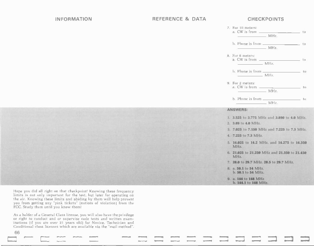
INFORMATION
Hope you did all right on that checkpoint! Knowing these frequency limits is not only important for the test, but later for operating on the air. Knowing these limits and abiding by them will help prevent you from getting any "pink tickets" (notices of violation) from the FCC. Study them until you know them!
As a holder of a General Class license, you will also have the privilege or right to conduct and or supervise code tests and written exam- inations (if you are over 21 years old) for Novice, Technician and Conditional class licenses which are available via the "mail method".
REFERENCE & DATA CHECKPOINTS
7. For 10 meters: a. CW is from to
MHz.
b. Phone is from to MHz.
8. For 6 meters: a. CW is from to
MHz.
b. Phone is from to MHz.
9. For 2 meters: a. CW is from to
MHz.
b. Phone is from to MHz.
ANSWERS:
1. 3.525 to 3.775 MHz and 3.890 to 4.0 MHz.
2. 3.89 to 4.0 MHz.
3. 7.025 to 7.150 MHz and 7.225 to 7.3 MHz.
4. 7.225 to 7.3 MHz.
5. 14.025 to 14.2 MHz, and 14.275 to 14.350 MHz.
6. 21.025 to 21.250 MHz and 21.350 to 21.450 MHz.
7. 28.0 to 29.7 MHz. 28.5 to 29.7 MHz.
8. a. 50.1 to 54 MHz. b. 50.1 to 54 MHz.
9. a. 144 to 148 MHz b. 144.1 to 148 MHz.
66

L9
6 allyM 8 ifeJJ L latol/1 9 anlg g uaaJD
b MottaA £ aSueJp
Z pall I UMOJg
o '1aelg
Hnzvn 11O1O9
1lib'HO 3ONt/OI3INJIS E10100
¡IulodYInayn pinb ay) Ájl ,Jagwnu leqM s)uasajdaj Joloa legM paJa)sew aneg norS Ja)Jy lJeyn anueniJluSis JOIOn alp aziJowaw o) noif lueM aM 'sJolon oMl asaql jo anueniJiuSls aql ujeal aM aJoJag Jantis pue plo0 ale sJotoa asa41, sJolsisaJ Suipon Jotoa ul pasn sJolon Ieinads Jaglo oMl aje aJagl lJego aqi ul uMogs sJolon asogl Ol uoilippe ul
JapJo Ieyl ui '6-0 sJagwnu agl Sui)uasaJdaJ sJoloo jo anuanbas aqi se awes ay) Si anua)uas agl ut pJOM pea ut sJallal IsJIJ Jo anuanbas aqi legl anloN ¡sulM ÁIleJauaO Ialoln Ing 'sung Suno,t Jnp aneb s,Sog Slg
:s! asn guys aM auo aqi 'JanaMoy 'óu[pon-JoIOn ul pasn sJoloo jo anuanbas aqi jo S,uiujeal rfsea atgeua 01 pasn salnlnJn snoJawnu uaaq aney aJaq f, Z uwnlO ul IJegn all a)oN pasn JOIOn gnea Jo anuentJiuSis leniJawnu aq) uJeal o) Si apon Joton ato SuluJeal ul dais Ief3iut ayd,
Jolon jo sadiJ)s Jo spueq se Jo)slsaJ aqi uo sjeadde Suipon JoIO ayy wa)sRs pueg aq) pallen si uJeal ol )ueM aM wa)sÁs ag,l
swgo ul amen SI! IeanaJ JolsisaJ aqi uo )nd aje sjolon ay) ÁeM ay) pue 'sJaqwnu luaJaJJip )uasajdaj sjotoa luaJaJJlp
slsaSSns aweu aqi sy Suipon Jolon pallen Si poglaw slg,l, JOlsisaJ e jo anlen aqi auuelS e le Ital 01 sueinlugna) JoJ alq!ssod )i salew ynlyM pastnap uaaq seg poylaw e 'suoseaj jag)o pue 'sigl Joá pua Jo apis aqi uo sjal)aI palulJd u! anlen niwgo magi aliJM o) alqissod -wi aq pinoM li 'azis u! Hews ÁllenlsÁgd aJe sJolsisaj Áuew asnenag
3003 1:10100 liO1SIS313 3H1
(sjolslsaJ asn Álsnoingo q3iqM) slinaJln 0y pue O4 Supfpnls uiSag noif se 'ajaq lgSij Suiujeal Jo Ilg leyl laaljalui mal os 'sal OOd aqi anel uagM apon Jolon aqi mom' o) paau 'l`IIM noif 'osty uo aiaq woJJ anllaeJd JoJ nof SutniS aq II,aM slinnjin aqi laauuon ÁIlen)ne uen noif os sJolsisaJ JoJ apoa JOton aqi nolf yneal JaI)aq p,aM 'legl op aM aJoJag inq
Mei s,w40 uo ani)neJd MatnaJ awos noÁ SuimS Áq uiSaq
S1d1N3WtfaNfl3 3V '8 30
asuany will ajmbne oI paau SuluJeal snae)sseJq aqi uiSaq pue uo anow II,aM 'IeJauaO eJo saSal[niJd pue sluawajinbaJ aqi SuipjeSaJ cap! IeJauaS aqi aneg noÁ ieqi MoN
lEJauaO ley! Sui)laS Jo leoS aqi qua 01 kjessannau Ápnls pue )joJJa aqi y)JoJ Ind noif ley) aJll JnoÁ Jo 'sal aqi JOJ Inplueql aq ll no,i,
salnuanbaJJ jo peiJrfw e asn JnoÁ JoJ algetiene aneq 'uolippe ui pue paujanuoa aje saSalinljd se jeJ se s)lenn 0001 01 slleM g woJJ auoS ÁlnJl aneg no,S 'asuantl sse10 IeJauaO JnoÁ IaS nolf uagM 'aas uen s
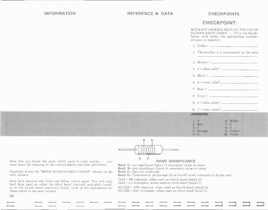
INFORMATION
Now that you know the main colors used in color coding ... you must learn the meaning of the various bands and their placement.
Carefully study the "BAND SIGNIFICANCE CHART" shown in the next column.
Now let's mention the Gold and Silver colors again. You will only find them used as either the third band (decimal multiplier band), or in the fourth band (tolerance band). Look at the description for these colors in the next column.
68
REFERENCE & DATA
B
C BAND SIGNIFICANCE
Band A-lst significant figure of resistance value in ohms. Band B -2nd significant figure of resistance value in ohms. Band C-Decimal multiplier Band D-Tolerance in percentage (If no fourth band, tolerance is 20 per cent. Gold = 5% tolerance, when used as fourth band (band D) Gold = 0.1 multiplier, when used as third band (band C)
SILVER = 10% tolerance, when used as fourth band (band D) SILVER = 0.01 multiplier, when used as third band (band C)
CHECKPOINTS
CHECKPOINT: WITHOUT LOOKING BACK AT THE COLOR SIGNIFICANCE CHART ... fill in the blanks below with either the appropriate number, or color as required.
1. Green =
2. The number 2 is represented by the color
3. Brown =
4. 3 = what color?
5. Black =
6. 9 = what color?
7. Blue =
8. Gray =
9. 4 = what color?
10. 7 = what color? ANSWERS:
1. 5 6. White 2. Red 7. 6 3. 1 8. 8 4. Orange 9. Yellow 5. 0 10. Violet

69
a3ue1aiol a/,0I qliM mOLt 'S a3ue.1aio4 %S 41iM )16C 'b
a3ue.1alol ooOZ 41iM Swgo O00I 'E a3uelajol "/,0I gl[M slugo OL 'Z
a3us.1aiOl %5 gIiM )I09Z 'i
:SiI3MSNt/
ranliS mop), lalotn MollaA g ping aBuerO aliyM a8ue.io y auoN pH veig timing E
ranl!S 'I3e1g nae¡g UMOrg 'Z
'Jam % swim PIoO
lollop tut MollaA
10100 Pr£ anlg
J0103 PuZ Poll '1 -
101op 1st
M0113A 03H
r/tII/fl \\1 0109 13101A
:1NIOd)133H3
39NtlHO NMOH9
031:1
£ uwnio3 ui uMoys 1ae40 asi31ax3 walsÁS pueg aqi ui Iiid ulnl rnoif s)i MoN
a3ueraloj %S e sueaw pueq ylb e se piog ayl pue tsragwnu oMl 1sri.I aqi raue soraz 6 sueaw pueq laildillnw e se pue 1 = Mof1aA aqi pue 'L = laioin .10103 puo3as alp :Z = pal '1o1o3 lsri} ay,1, a3ueralol %S 41!M Swyo 000'0LZ :si amen S11 rap.10 4e41 ui 'pioa-MoIIaA-laioin-pa21 papo3-roio3 Si lolsisa.1 d
:aldwexa arow auo s,a.1aE{
suoile3iii3ads sli ol dn pang li 'swgo »'bi pue N96 uaaMlag arayM fue a1aM rolsisaa s143 1i 'spsoM raylo 111 a3uesaio) ui aq Ilgs pue >IZL anoge %OZ se amen ui g8iq se .10 a3uerajo4 ui4liM
aq tills pup mu papo3-roio3 aqi Moiaq %oZ se ante ui Moi se aq pino3 rolsisal siga, siql rCldwiS ¿a3ue.1aiol Áq ueaw am op leyM
'%0Z Si a3ueraiol rolsisal alp '1o)sisal sigl uo pueq 10103 411no; ou seM alayj a3uiS
'SIZi .10 'sw4o 000'ZI st amen au, (sragwnu lue3i;iu8is oMl 1s.111 am' ra11e ppe 04 soraz Áuew Mo4 noR sflal Áldwis pueq laildil¡nw aqi a3uis) 'solaz aar41 paMoilol ZI uMop
alirM pinoM 'lolsisal ay) jo amen ayl la8 0l gay' ''' £
sueaw a8uero pue pueq satldilinw 10 'pueq prtyl ayl si aSue1O a3u[S Z = pag a3uis 'Z aq pinoM ragwnu puo3as ay f, I sluasaldar uMo.1g a3uis t aq pinoM anien s solstsar aqi u! lagwnu )sri} ayy
:li apo3ap norS Mo4 s,aray aSuelp seM pueq prigl pus 'pa21 seM pueq puZ 'uMo1g seM pueq 1st asoyM lolstsar e le 8uplooi araM aM JI :aldwex3
pal.1els la8 noÁ diay 431 saidwexa;o aldno3 e noÁ anta s,lal 'swaf9old a3j3e1d awos noK ani8 am aro,{ag lsn(
noÁ 01 arnleu puo3as awo3aq (IiM li .1an3inb ayl 'li Suisn a3113e1d noÁ a.1ow ay,1, ¡yI 3S11 SI 32I3H A3x 3H.L Puiw ui !jam apo3 1mo3 aq) aney noR ~jag awil )Joys e aq /quo IIiM li 'a3il3e1d Ien13e Áq UOilewrojul siyl asn noÁ se leyl pull iliM noy, apo3 10103 aqi Suipear a3ij3e1d noÁ jai pue .iaylaSol lle li Ind s,lag ¡Renp

INFORMATION REFERENCE & DATA CHECKPOINTS Did you catch that tricky one with Black as the third band? When- ever black is used as a multiplier (third band), it means to add "zero" zeroes . . . and simply read the first two significant digits . . . in our sample the value is 10 ohms. Remember this one, for it appears quite often in real life. Also, we could have tricked you by putting gold or silver in the third band position. All you have to do is move the decimal in accordance with the color. Example: if the first two numbers were decoded as 15, and the third band was Gold (a 0.1 multiplier) . then the resistor would be a 1.5 ohm resistor. If Silver were the 3rd band . . . the value would be 0.15 ohms.
THE ONLY WAY TO LEARN THE COLOR CODE IS TO USE IT! We realize that we don't have room enough in this book to give you all the practice you need . . . so it's up to you! Every time you see a resistor . . . "decode it". It's a lot of fun to see how quickly and accurately you can decode it. You'll be amazed at how quickly those colors will almost look like numbers to you, if you will practice. EA RI 10K CHECKPOINT: Look at the diagram in column 2 and fill in the appropriate blanks in If the current meter is reading 2 mA . .
the checkpoint in column 3. HINT: Start by writing the OHM'S LAW What is the value of the "applied voltage"? formula for voltage . . . then substitute the appropriate values of current and resistance into the formula. Use the blank space on these EA = volts. pages for your calculations, etc.
That wasn't bad was it? Here's another little hint ... whenever you multiply milli -units times kilo -units ... the answer is in units. The reason is that a milli -unit is "one -thousandth" of a unit and the kilo - unit is "one thousand" units ... so when you multiply one -thousandth by one thousand you "end up" with 1.
Let's see if you remember the power formula. For the same circuit .. .
how much power does R dissipate? Don't forget, in order to prevent simple errors ..
1. Write down the appropriate formula, then . . .
2. Substitute the appropriate values ... keeping track of the decimals.
Work out the answer and fill in the Checkpoint blank.
ANSWER:
EA = 20 volts
Here's the procedure:
Ohm's Law formula for voltage is: E=IxR Substituting, we get: E = 0.002 A. x 10,000 ohms = 20 volts.
CHECKPOINT: The power dissipated by Ri (PR1) =
mw. (milliwatts)
ANSWER:
40 mw.
70

lL
5110A8L=1213 S¡IOA ZL = za3
'VW I ZaI .VIII i = aI
:Sli3MSNV
s'ion = 1113
111 ssoa3e doap aSelion ay! alein3ie3 ue3 aM 'osld s'ion - = Zas :se Zs ss0a3e doap aSellon aqi aleinaie3 uea aM 'a3uelsisaa s,Z21 pue Z21 ySnoayl luaaan3 alp SuiMoux
Vw Vw
Si L21 ySnoayl lUaaan3 ay l aq isnw z2J ySnoayl
'uaaan3 ay1 '11naa13 salaas e si siy' a3uis
Vw (21/3 = I :WIN)
aq isnw c3 ySnoay' luaaan3 ay! 'sllon OL speaa aalawlion aqi JI
1NIOdN103H0
Z3 = d .Z
2I`I = d I a3MSNV
=d ¿asn noR pinoM einwaoJ y3lyM 'a3ue -'slsaa pue aSelion si uMoun Si 1e41 Ile ji
= d ¿asn noS pinoM einwaoJ aaMod y314M 'a3ue
s! 1e41 Ile JI lslsaa pue 'uaaan3 Si uMoun
INIOdNO3H0
'Z
'1
iNOn e Suisn jo laalgns aqi uo saysllgnd reys olpeg loog aqi le looi ol lueM lySlw 'll le aae noif ail4M ala 'saSelion aqi Sul -anseaw Á lien'3e Áq suoileln3le3 asaqi ÁJlaan ue3 noÁ '13e11s olpell le dn way' 13id 01 lueM JO 'sped aqi aney norf Ji leyi lsaSSns sn la`I
suwleln3lea anoR aoJ saSed asayl uo a3eds nuelq asn alelad -oadde se c uwnio3 ul snuelg aqi ul l¡IJ pue z uwnioa uI weaSelp aqi le 1001 13eJ styl sasn ley! walgoad leatl3ead e norC anlS s laj
slinaat3 salaas azÁleue noÁ Suidlay ul iSeM Suoi e oS II1M 1i-13eJ slyl aagwaw a21 iS3I>I3S NI S.LN3IN373 77d H9f102IH.L 31/11dS 3H.L SI .LN3N
-2If13 31-1.L :SI S1I1132I0 SHIMS .Lf1OHN 2I3HW3W321 O.L S.LOHd A3?I 3H.L .30 3N0 'saolslsaa alp ile ySnoayl sassed luaaan3 awes aqi ley' sueaw siy,I (Áaalleg) a3anos ay1 jo apis anlilsod ay' 01 )13eq uayl uay''zZl uayl'E21 ySnoay'ssed (ailewayas aqi Jo wolloq) Áaalleg aqi jo apis anileSau aqi anea! suoal3ala aqi ley) if ES
pino3 aM 11n3a13 sigl le Supiool 13aaao3 aaaM noÁ 'auo pies noif Ji
¿aas noR op luaaan3 ie3lal3aia aoJ SH.Ldd Ruew Moy 'm3ai3 saws e jo weaSeip s1y1 le Suploo1 uo os pue E21 jo pua auo ol sl3auuo3 Z21 jo pua aay'o ay1 'Z21 jo pua auo ol sl3auuo3 `21 jo pua auo ,1AO4 a3tloN
' lin3al3 saws luawaia-aaayl e jo 3lleway3s aqi ul palealsnlll si sly' Moy aas uley3 e ul snutl anii-wapue' ui pal3auuo3 aae s'uauodwo3 ie3lal3ala JO
sluawala aaow JO oMl aaayM llnaal3 e Ridwis si lin3ai3 saws y S1.Ifl3 211H S3I2I3S Jo s39sla913eae43 luelaodwi ay1 ssn3sip pue Mou uo
anow s,'ai os panionul luauodwoa auo uey' aaow aneq IIIM azifleue o' aney IIIM noÁ s'maal3 ltn3al3 ao'sisaa-L aidwis e seM 1eyL
11f1oM10 S3I1:13S 3H1
lulod>i3ay3 lxau aqi Áa1, suMoul se tie 3 pue 1
pey noÁ a3uis 'einwaoJ 21/;3 aqi pue einwaoJ 21 x Zi ay pinoM os pavoM aney pinoM'eg,l, ¡aans ¿einwaoJ I x s= d ay' asn norC pip

INFORMATION
Let's take a closer look at our three -element series circuit and "pick- up" some other very important facts regarding series circuits.
Fact: THE TOTAL RESISTANCE OF A SERIES CIRCUIT IS EQUAL TO THE SUM OF ALL THE INDIVIDUAL RESISTANCES IN SERIES! For our sample circuit then: RT (total res.) = R1 + R2 + R3 Thus: RT = 18K + 12K + 10K = 40,000 ohms (40K).
Another way we could have solved for R total is by using Ohm's Law as follows:
RT = ET/IT which simply means total resistance = total voltage divided by total current ... so for our sample circuit:
RT = 40v/ImA = 40K ohms.
Many, many times in working on electronics calculations you will be using this version of Ohm's Law . . . so here's another quickie hint at no extra charge! Whenever you divide units by milli -units . . . the answer is in K units. Most of the time when you are solving for resistance in electronic circuits you will be working with volts and milliamps . . . so remember this statement . . .
volts divided by milliamps = Kilohms.
Let's look at our sample circuit again and make another important observation. FOR SERIES CIRCUITS: THE APPLIED VOLTAGE (EA OR ET) IS EQUAL TO THE SUM OF THE INDIVIDUAL VOLTAGE DROPS!
For our sample circuit then, EA (E applied) must equal ER1 + ER2 + ER3, or in other words: 18v + 12v + 10v ... hence E applied or ET = 40 volts.
Putting these three important facts together (regarding series cir- cuits) ... you have tremendous flexibility in solving series circuits. Those 3 key facts again are:
1. Current is the same through all parts of a series circuit.
2. Total resistance is equal to the sum of all the resistances.
3. Total voltage is equal to the sum of each of the individual voltage drops.
O.K. Here's a "brain twister" problem to see if you can begin to apply these facts to a practical problem. Give it your best effort! Try not to look ahead to the answer until you've really given it "a college try".
72
EA 40V
EA 60V
REFERENCE & DATA CHECKPOINTS
I= 2 mA
10K
10K
CHECKPOINT: For the circuit shown in column 2 find the following:
ER1 = volts ER3 = volts ER2 = volts
R2 = K ohms IR, = mA.

(slleAIc1I1w) Mm OZL = yd 'VW Zxn09=jd
j[x =yd :e¡nwjoJ ay1 asn Aldwts
'Ie1o1 1 pus Ie)o) g MomI am a3uts 'ase) scyl ut 'jo jatiod ¡elo1 la8 ol dn wag) ppe uaqi uot)edtsstp jaMod s,joistsaj lenPln -cput g3ea amos jar{1a uea am '(uocledtsstp jaMod ¡e)o1) id s,ltn3jt3 aqi Joj an¡os o,I,
Ima.t13 sacjas Aue 1nogSnojyl awes ay) sc manna aqi aaurs 'dw Z Alsnopnqo sc (Erg) E21 Orion) Iuajjn) agy
H0L = HwZ/n0Z j0 zaI/za3 = z21
:e¡nwjoJ alp asn uaqi ue) noA ')tn3 -j1) satjas e sc scg) aaucs bw Z aq Isnw z3
g8nojgl manna ag1 Imp SutMoun pue 's)Ion OZ st za3 ;ey1 I)eJ ayl Sutsn )1n3jt3 all) 04
parldde s)Ion 09 sr alai) pue = Ea3 +
Lag a3ucs s1¡on OZ aq 0I seg za3 imp pue)s -Japun oi sc an¡en s,z21 pug 01 AeM jayloud
sljonOZ=?IOL xVwZ=zag Á e ue3 noA uaqi )I0I. = z2i )ey1 SucMoux
£L asn o1 yaeojdde
ay) azilenstn pue 'Sup¡uiyl Jnof. azlue8jo noA dial] Allensn !pm sly sI3eJ uMoui aq) gum Alaleijdojdde weaSeip aq) ¡age¡ uay)
uani8 )ou sl auo Jt wejSecp e alew 'algissod uayM SN3/1I0 QNd SNMONN 2If]OA g7d .L037103 04 st swalgojd )tuojl3ala áuinlos .toJ alnj lejauaS t/ jayloue uo sa8uty l)eJ auo M0y aas
'NM ¡enba Isnw z3 'olSo¡ Áq 'uayl 'saaue)stsaj ¡en -ptnlpul alp jo wns aq) slenba Itn3j13 sayas e u1 j.g a3ucS ')IOS =NwZ/n09 SniPlarA '(Ie1oI I Áq paptnlp patldde g) yI/va = y21
:elnwjoJ al]) Sucsn Aq gF/,I,O,I, g pur. :Alaweu 'yoeo.tdde joop >I3eq jayloue, gSnojyl st AeM puoaas
H ¡Si .LI QNt/ 73 Áq paddojp aq Isnw sl¡on in 8ulutewaj ay) sAes 31801 uay) s110n oz Suiddoap gaea aje pue '21 ley) pue
Irnajt3 saljas spy 01 palldde sllon 09 st ajayl ley3 SutMoun puE 13eJ s1y1 8ucsn sdojp a8ellon ¡enptncpuc agI ¡Ie Jo wns ato o; Ienba sc prima sacias e Joj Mellon pa1¡ddd jo Lelo,L ay) le141 13eJ ay) Sutsn s1 AeM auo
:asn IyScw n0A say3eojdde A;Jru onni aje alai) 'za3 pug oi jap3o ut :lljno.
*limn OZ IaS noA pue (>IOL( `21 saw!) (Hw Z) `2I y8nojyl Iuajjna at)) fldtllnw A¡dwls fag pu11 oi pjtg.L
sIIOAOZ=>IOL x 'VW g='ag L11x(11148110jy1)I=`ti3
:ase3 scgl ut sjagr:jnu aiecjdojdde ato aln)tlsgns pue Mel s,wgo asn ALdwts noA Lag pug 01 puo3ag
`2I y8nojyl osle pue z3 g8nojyl pue L3 gSnojy) SucmolJ Iuajjna Jo -dw Z sc any) 'ajoJajal]l
awes ay) s1 Itn)jta satjas e jo sped (¡e Orion) manna aqi IOW Ile3aj ;s.n.
:Joj pallen sjaMsue alp 8uc1la8 pue Itn)j13 sty) 8ucnlos o) y3eojdde ¡e3tdi1 aqi st ajaH
:S413MSN V uotl)as sjaMsuy ay) uc sjaMsue pue uotleueldxa
ay) Ie 1001 'All asallo3 aq) 11 uant8 an,noA imp Mo¡q ¡IyBcj Ild

INFORMATION
O.K. Let's make mention of a couple more facts that are very practical . . . even though you may not be called upon to analyze a circuit with these conditions on an FCC exam.
Fact number one relates to the effect of an "OPEN" in a series circuit. By an "open" we mean that for some reason or another, the current path is broken through a given part of the circuit. For example ... if a resistor were to physically break in half, it would create an open. If ANY PART OF A SERIES CIRCUIT IS OPEN ... THE ONLY CURRENT PATH THROUGH THE CIRCUIT IS BROKEN ... HENCE CURRENT WILL DECREASE TO ZERO THROUGHOUT THE SERIES PATH. Of course, an open can be caused by a wire becoming disconnected from a terminal or component, etc. When current is zero, then the IxR drop across all other components, except the open one, is zero. Across the open portion of the circuit, one would measure E applied, since there are no "IxR" drops to sub- tract from EA . . . THE POTENTIAL DIFFERENCE ACROSS THE OPEN WILL BE EA.
Fact number two relates to the effect of a "SHORT" in a series circuit. If any resistance is shorted out (becomes close to zero ohms), then R total will decrease ... causing I total to increase. If the current through the circuit increases ... then the IxR (voltage) drops across the "unshorted" components will increase proportionately ... and the voltage drop across the shorted part of the circuit will decrease to zero . . . since E = IxR, and R (for the shorted portion) has become virtually zero . . . anything times zero is still zero, hence E = zero.
Of course there are many adverse effects from a "shorted" part, or all, of a circuit. Everything from blown fuses to destroyed circuit elements can (and often do) happen when shorts occur. How much damage is done usually depends on how much "unshorted" resis- tance is left in the circuit to limit current.
Here's a summary of key facts regarding series circuits ... remember these and understand them, and you will be able to "think your way" through almost any problem involving series circuits.
Facts: (for series circuits)
1. Total resistance (RT) equals the sum of the individual resistances ...or: RT = R,+R2+...and so on.
2. Total voltage equals the sum of the individual voltage drops or:
ET = ER1 + ER2 + . . . and so on.
3. Total power equals the sum of the individual power dissipations,or: Pr = PR, + PR2 + ... and so on.
REFERENCE & DATA CHECKPOINTS
74

5L
'S.Ld3DNOD 3H L aNH.LS2I3aNf1 01 ing s1uel asagl azlaowaw Di lou /fa1, ajlI ano.f jo lsaa aqi Ham norf anaas IIiM pue s1siSleue llnano Ile 01 Ieuollepunol ÁIleaa sl paaanou lsn( aney legM dwnl auo ul Sluel Áuew os noif SulnlB Áq norf paWeanousip l,uaney am adoq 1
anlen auuelslsaa lsay8l4 ay1 jo aOISISaa ag1 SSOa3e 1sa48l11 aq IIIM (doa) 21 x I) 3 aqi `aa1laea suoseaa Jo{ 'pud aaMod sow aqi aledlsslp IIIM doap a8ellon lsay8111 041 91lM luauodwoa aqi uay! sluauodwou 11e g8noagl awes aqi s! 1 pue '1 x g= d auuls 'aas ueu noS s1/ (NOI Lf1HI21 LSIa 30H.L3O/1 31-I1 SV H3a1 3WHS) 'JaMod Isow 0y1 aledlsslp IIIM aolSlsaa amen IsaBael aqi `1ln3alu SOLIOS e ao3
¡a8ellon awes agl doap 11iM anlen lenba jo saolslsaa Ilnualu saldas e ul legl lno slulod osle pe.; si41,
'E21 paddoap aq IIIM palldde 3 jo 410i/L 'uayi auuelslsaa Ie1o1 llnualu 0y1 jo glOL/L o! lenba sl .Il sueaw sy,1,
..i3DNd1SIS321 3N.LO.L.40 SI 3111N/13aNH.LS1S321 S..LN3NOdWO3 SIH.L SV 3WHS 3H.L SI .LN3NOdWOD N3A13 ANV All 3dd021a a3I`IddH 3 dO 30N1.N3D2I3d 3H.L ''' lulod Sullsaaalut Áaan e inoqe s8ulaq sly,1,
'3 jo leyl alqnop aq pinoM doap aSellon S,z21 uagl j101, Sl i3 pue >IOZ St 21 II SpaoM aaglo UI llnaalu aqi u[ s,2í aaglo aqi ol paied -wou lI SI! 01 palelaa Si luauodwoa uani8 /fue Ssoaue doap aSeljon aqi leyl snolnqo sawouaq Il 'uagl sopas ui sluauodwou Ile y8noayl awes aqi sl 1 041 pue g x 1 01 lenba sl doap a8ellon guea OuulS
:s11n3alu sataas uo uolssnusip 0¡311¡ ano 8ulpnluuo3 ul Ino lulod 01 anll pinoM am suollenaasgo leull awos
auo slg1 uo a8uiy sluel aaglo ÁueW '.LIf1a21ID S3I213S b' .Lf10H0f102IH.1, 3WHS 3HL SI .LN32121f13 31-11 SI 2I3HW31N321 01. 1.3H.1 Aix 3H1. 'L
Mo11e pinoM lu0aanu pue aBellon jo auanos aqi se 48lg se oa pinoM luaaanu 1e1o1 041 pue swqo oaaz awoaag pinoM aouelsisaa 1e131 aqi 'palaoys aaaM .Llfla -21ID 370HM 041 JI aseaauul IIIM luaaana 1e1o1 pue ase0auap IIIM lln3alu 041 lo auuelslsaa 1e101 'llnualu salaas e ul SanuuO laogs e;l
g8lg ÁlallutIul sawouag llnualu 0y1 jo auuelslsaa 1e1o1 0y1 pue oaaz 01
aseaauap f11M luaaan3 lelo! aqi '31n3al3 sapos e ul sino uado ue J1
pazifleue 8ulag llnaalu 041 jo uoilaod 0y1 aoI sanlen aleladoadde ay1 8ulsn ifq rfldwis lmaalu a1oyM 0111 ao llnualu sayas e jo laed Áue aoI sanlen amos 01 pasn aq ueu selnwaoj aaMod ay1 pue selnwaol Meg s,wy0 ay,l,

INFORMATION
Let's see if you can "put it all together" and solve an interesting series -circuit problem. Get the "info" from the circuit in column 2,
REFERENCE
FROM
& DATA
and determine the answers asked for in the checkpoint. Calculate as required in the blank portions of these pages ... if possible when through . . . verify by actual circuit hookup and measurements.
VOLTAGE SOURCE +
Rl 4.7K
Good luck! EA R2 2.2K
=1.5V
ANSWERS:
As a form of review . let's "logic" you through this problem step-by-step.
RT, or total resistance, was the first electri- cal parameter asked for. By remembering that in a series circuit the total resistance simply equals the sum of the individual re- sistances ... you should have simply added 4.7K + 2.2K + 1.0K and arrived at 7.9K as your answer.
Next parameter asked for was total current. Here's a key step in solving a series circuit. Once you know the current through any part of a series circuit . . . you automatically know the current through all the components in series, since the current is the same through all parts of a series circuit. Just about everytime you have a circuit problem . . . the first thing to look for is any part of that circuit ... or any component about which you know . . . or are given TWO KNOWNS (or parameters). In this case we have such a condition for R3. We know its resistance value, AND we know the voltage dropped across it ... so we can easily solve for the current through it by: la. = ER3/R3. From this we get: IR3 = 1.5v divided by 1.0K ... and thus IR3 = 1.5 mA. Since the current is the same through all parts of a series circuit ... this is also the value for I total ... therefore, IT = 1.5 mA.
76
CHECKPOINTS
CHECKPOINT: Find the Following:
RT =
IT =
ET =
PT =
ER, =
PR2 =
What fractional part of EA is ER,?
Now that we know the current through all the components, and we were given each component's resistance value . . . we have TWO KNOWNS about each component and the rest is easy.
To solve for total voltage (ET) we simply use "good ole Ohm's Law" again: ET = IT
x RT, OR, ET = 1.5 mA. x 7.9K = 11.85 volts.
Next on the agenda was total power calcula- tion. You should have written down the for- mula: PT = ET x IT and substituted: PT =
11.85v x 1.5 mA to get the answer: 17.77 mW. (milliwatts). Incidentally, you could have used: IT2 x RT, OR ET2/RT and gotten the same results. Usually it's easier though . . . if you know both E and I, to use the version of the power formula that doesn't require any "squaring" . . . because then you have to perform two mathematical func- tions ... "squaring" and then either multipli- cation or division (depending on which for- mula you used).
O.K. To solve for ER,, just multiply the cur- rent through it by its resistance value to get its "IR" drop. Answer is: 7.05 volts.
To get PR2 requires two operations no matter what approach you use . . . so let's use IR22
x R2 here, and get: PR2 = 1.5 mA2. x 2.2K = 4.95 mW. (Watch out for those decimals whenever you square with them.)

LL
syinoaD lalteded o; uo anow o; awiy s,41 '>1'O
suMounlun antos o; pasn aJe setnw.io3 Jamod pus Meri s,wyp (oya `;sa8iel si N a.iayM ¡salmi aq
(PM Ix3 uaqy lle 0no110 awes s! )¡ aouis uo!ongla;s!p 3 ato se aldpupd awes) a;a ;sane! uo ;sa;eaa8 s! uoi;edissip .iaMod
(a;a ' oseal ag; g ;sallews 'a8e;ton ;sow sdoap ;sane) `aaoia.iayy) uo!; -nqia;sip aoue;slsa.' se awes si ;lnana punoae uol;ngh;sip a8eoloA
s.d Ile ,to wins = d 'cloy s3 lie Jo wns = 3 mu, sa2I lie Jo urns = a leyoy
;noySnoay; awes ay; s! ;uaa.inD ;uaa.ino .io) toed auo iftup
'L
'9 'S
'E 'Z
:aae ;inoaio saiaas ayy inoqe aaqwawaa o; sSu!y; &a>( ag; '8ui;eadai3 noÁ oy dlaq awos jo seM sJaMsue ayy jo uo!ssnosip days -Áq -days pue walgoad aim! yelp leg; ;snay
ueloiuqoa; oiuoa3oala ue ao/pue anayewv aipeg e se sawio Áuew ;oe1 yelp asn ll,no,t aoue;slsa.i ,lo uoiynqia;slp aq; se awes aq; s! ;mama salsas
e punose aSe;lon jo uoi;ngiaysip alp yelp loci agy si gSnog; aaay yno Sulsg o; ;ueM aM yuiod &anl ayy 3oasaoo /fl;oa}aad aq IiRs pue ' vg jo syysg'IL/S'I oy lenba seM elrd yell pies Áldwis aneq /few norf os - yelp Papel -noleo norf asneaaq s;lon ggLi seM vg imp main no& 'osly ;ely no& aneS aM asneaaq `sylon gi seM eyrd ley Main¡ Ápeaale no,t
= 6'L/n5e'ii HO ' v3 .i° 416'L/L do.ip IIiM y! 75 aoue
;slsaa leyo; ayy;o q36'L/0'L si aoueysisa.i s,Eg
xO (s;inoap saws ao3) ag jo y.ied leuoly -ow; s,yuauodwoo yelp se awes agy si ;uauod -woo &ue ssoaoe paddoap v3 jo ;aed aq; ;egy yuawa3eys ano aagwawag sso.ioe paddoap, seM aSe;lon palldde aq; jo ;sed leuo!p3ea1 ¡Kim ao.; pase aM ¡seal ;cu ;ng ;seZ
(1uo3) Sa3MSNV

INFORMATION
THE PARALLEL CIRCUIT
The reason we took so much time looking at principles and concepts in series circuits was because you will be using the same general approach in solving all types of circuit problems, and we wanted to give you a good foundation to work from.
Remember that a series circuit could be defined as a circuit where all the components were connected "in tandem", and there was only one path for current flow ... well, a parallel circuit differs in these two basic points. First, a parallel circuit is one in which there are TWO OR MORE CURRENT PATHS. Second, the components ARE NOT connected "in tandem". Study the pictorial and schematic diagrams in column 2 illustrating these facts.
Notice that when total current leaves the negative side of the source, there is one path . . . but soon it arrives at a "junction" where R, and R2 join ... and the current divides into TWO paths (I, and 12).
I, passes through Ri . .. 12 passes through R2 ... then the two cur- rents JOIN again at the top of R, and R2 at the junction of those two resistors, and we now have total current (II + 12) traveling from the junction back to the source through the single -wire path. As you see ... the parallel circuit offers more than one current path. Also, the components are not connected "in tandem", but rather "in a parallel configuration" with "ends common."
Since their ends are connected together, another valuable fact to remember about components "in parallel" is that the VOLTAGE ACROSS ALL PARALLEL COMPONENTS IS THE SAME! In the case of a "simple" parallel circuit, the voltage across all "branches" is equal to E applied . . . since they are each in parallel with the source as well as being in parallel with each other.
Notice, we used the term "branch" to indicate one path.
In our earlier illustration then, I, represents the "branch current" through R, and 12 is the symbol we used to indicate the "branch current" through R2.
This brings us to a third important fact to remember about parallel circuits. Each branch current is INVERSE to its branch resistance. This simply means that the higher the branch resistance . . . the lower the branch current. Makes sense doesn't it!
Ohm's Law told us that current is inverse to resistance when it says that I = E/R. This means that if branch No. ] has twice the resistance of branch No. 2 . . . then the current through branch No. 1 will be half that of branch No. 2's current . . .
since both R's have the same voltage across them.
REFERENCE & DATA CHECKPOINTS
CELL Pictorial of a
Parallel Circuit
Schematic of same Parallel Circuit
78

'Mw SI '6 .Vw S'L '8
5 Mw OL '9
'nOL `n0í `nOL 'S
Vw 5'0 17
Vw i '£ NOZ 'Z MOL 'L
:Sa3MSNtf
¿Id jo amen ays s! seism 6
Mw
Mw
jo amen ay, s!
jo arisen ay, si
V
_o arisen a4l sl
¿'a3 _o arisen ayl s!
¿9 luaJJn3 y3ueJg _o ansen ays Si
111911[19 yaueJq jo arasen ayl s!
.swyo x
swyo 3
¿Z3 _o amen ayo sl
¿2I jo alien ay' s!
:1NIOdM33H3
¿y1
let -IM '9
¿Zad Ie4M 'L
¿' ad le4M '9
¿ Za3 le4M '5
= Zs
Ie4M 17
_ '1
Ie4M '£
='2I Ie4M 'Z
=
sew '1
3`JNtYO Nov -t8
a 3h1
6L
()tn3Jla 0y1 lnoySnoJyl suolledlsslp JaMod senpinlpu! ays l¡ejo wns 041 ssenba Jannod sews 'sl ley,j,) ¡,j,Ifl32I13 3O QNDI ANIV 110,4 3f121.L SI .L3V3 SIH.L 'yI x v3 05 lenba osle si lensn se 'pug lin3Ji3 ay) ul suo!sedssslp Jannod lenp!nipu! ayl lle jo wns ays Si JaMod lesol ley) si alew ue3 am uoilenJasgo 1ay,ouV ¿1! l,usi sl!n3J13 saiJas woJ_ alisoddo alp s,ley,L ,.i213MOd LSOW 3H.L S3.LVdISSIQ HDNV2I8 3DNV.LSIS32I .LS3TIVWS a4 l' lin3Ji3 1a11e1ed e ui flaweu legs woJ_ sal am uolsn13uo3 Su1lsaJalul ue s aJasy ¿L oII yauelq Ág paledisstp ley, _ley /quo seM Z
oN yaueJq sly paledlsslp JaMod 041 say3ueJq ylog sso13e awes ays seM 3 ays a3uls legs a3lsou use noÁ plQ ¿sySlJ sn plol wyO uowlS aS1oa0 plo an!! lsn) ¿luaJJn3 ays _¡ey pue LoN yauelq jo a3uessisaJ ay, a3lMs pey ZoIv y3uelq ley, aallou noÁ pla
¡op s,lal os suolsnl3uo3 In_ -Su!ueaw awOs se anlJJe os aisle ay pinoys aM ¡aw!l uollenJasgO 'N'O
331Inos A 0 1T
suoiseln3le3 JnoR Jo_ sabed asayl uo sa3eds luelg ayl asn lul0dl3ayg ay) ul palmbaJ se suoileln3le3 wJo_Jad os uollew -Jo_u! slq1 asn ua4s Z uwnlo3 ul weJSelp sellos3ld ays se looq
pl3ny poo0 l!n3J3 tasseled e Sulnlonu! walgold e amos os
Jay:aSos -31a s,w40 'apoa Joloa snows ÁssnoinaJd pauleat an,noR lie snld slae_ 00141 asayl Ind noÁ aney s,lai il48!J ltV
ansen a3uasslsai ss! os asJanus s! yauelq uanlS /fue tSnoJys suaJJnf) £
awes asp s! ssuauodwoa 1a11e1ed ssoJ3e aSessoA y Mos_ suaJJna Jo] toed auo ueys aJohs L
:sl!n3J!3 salleled os pJeSaJ u! Je_ os pauolsuaw "am spej Iue,Jodw! aalys 0yl s,alay '>I.O

INFORMATION
OK ... here's another practice problem for parallel circuits.
é
Hope you did well on this. We'll think through it here so you can check your method of solution.
First ... we know that EA is going to be the same as the voltage across any of the branches. Since we have "2 knowns" about branch No. 1, we can solve for ER1 easily. 3mA. x 10K = 30v. Hence, we know that EA is 30 volts.
We can see that branch No. 2's current is half that of branch No. 1 . . . so we know that branch No. 2's resistance must be TWICE that of branch No. 1. This means that R2 = 20 K ohms.
We know that branch No. 3's current must be the same as branch No. l's . . . since it has the same E and R . . . thus, 13 = 3 mA.
Total current for a parallel circuit must equal THE SUM OF THE BRANCH CURRENTS! This gives us 7.5 mA. for the total current.
The power dissipated by each branch resistance can be calculated simply by using the product of the branch E and the branch I. This gave us 90 mW. for branches No. 1 and No. 3, and 45 mW. for branch No. 2.
80
REFERENCE & DATA CHECKPOINTS
IT
IT
CHECKPOINT Solve the circuit shown in column 2 for the following:
R3 10K
1.
2.
EA = V.
R2 = K ohms.
3. 13 = mA.
4. IT = mA.
5. PR, = mW.
6. PR2 = mW.
7. PR3 = mW.
8. PT = mW.
ANSWERS:
1. 30 volts. 2. 20K ohms 3. 3 mA. 4. 7.5 mA..
5. 90 mW. 6. 45 mW, 7. 90 mW. 8. 225 mW.

.swyo Hs
:!l3MSNV
swqo = y3
uwnioo luaae(pe aqs u! uMoys s!n!n ass Jo auuess!sar lesos aqs roJ apios pue einwroJ wns ass rano snnpord all asn
1NIOdM03H3 >101 Zd
1.8
uo os pue swyo NZ ro MOs JO glg/g INna3 Qqf]OM Ls sagnuerg xOl iaiiered an!J aneg aM J! 'anuall saqauelq 2i lenba Jo ragwnu plot ay) ,Cg pap!n!p s,)q yaueag aqs Jo auo sayauerg Iallered lenba asays lle Jo a3uels!sar lesol ,ualen!nba ato sagauerq anuess!sar Ienba q'!M lutr.n3 lallered e ul :s! ol uMop silog lie s!gs lelM gnuerq auo Jo legs prE/I aq II!M y3 'a! no& pips ssnI aM seyM anord pinogs ll lesos
ale¿n31e3 pue Meq s,w4O asn uags ¿elos i pue sluarrnn gnuerq alp asein3ie3 pue lion s: Jo pa!idde 3 ue pue iaiiered u! sross!sar NI amp Su!neq s!nnr!u e Merp os no& aSuailega aM
pa!idde 3 awes ass gl!M s!nar!o ross!sar aiSu!s e Jo luarrna all saw!, aarys aneg II!M satpuerg ¿enba aarsl gstM slnnrp e legs aas ueo no& u!eStl sayauerg ags Jo auo ifue s;/s o, ienba aq ii!M saynuerg aarls ags Jo nuess!sar (sua¿enlnba ro) iesos alp S3H3Nb'21H 2I Zb'17Ó3 332IH1 ql!M l!nurla lallered e aneg aM JI aarSap raysrnJ e o, pa!rren aq uen s!y,I,
21 ay] Zh = I ayl an!Ms Rg pap!n!p 3 awes alp 'sngs ts! u! s,Jl aqs Jo auo Aluo sslM s!narlo e Jo legs an!Ms aq
11!M suarrnn ielos ag1, sno!nqo s! uosear ag1, a 4311erg ragl!a Jo 31b'H 3NO aq ii!M oMs aqs Jo apuesslsar .LN3`Ib'A1f1Ó3 al -11
lal¿ered ut sross!sar anlen `ItInÓ3 oMl aney norf LanauayM ragwawar os soeJ Su!ssarasu! ue s,aral-1 ¿noÁ roJ )iroM s! p!p
¡wa¿qord sttis uo s! Áry
l! asn os ame aq os sue op aM snq einwroJ suss Jo suo!sen!rap len!'ewatisew al' lie u!eldxa os &rs s,uoM aM einwroJ Wf1S 31-11. 213AO 3H.1. pallen saw!' Ituew s! s! -1,L
Za+'2J ZN -ya
:s! r.21 Su!nios roJ slmnrp lailered roJ ragwawar os einwroJ Áa)I a41, aouess!sar ¿esos ass roJ anios os amp aq os sueM no& pue l!nor!o alp u! san¿en ross!sar alp mow! &luo !pm notf 'gSnoss 'sawisawoS iesos 2í Sulpn¿ou! 'smor!p e u! ralawered Áue roJ anios ueo norf 'suantS gSnoua aney nof uagM legs awl Si 55 ss!nnr!o laliered roJ HZf1W21Or1 .LNt/.I.21OdW1 A213A e os sn s8u!rq sum,
yI
173-= r2l pue yi ratiS!g aqs syled suarrnn arow ags 'anuag roJ suarrnn satlddns aarnos aqs legs tiled luarrn3 raysoue
saptnord l3uerq laea asnenaq s! 'asrnon Jo uosear a41, ¡FuNH2113 33NH.LSIS32I .LSd3'I 3H1 Nb'H.L SS3q SI 1!nnrla 'alluded roJ anuesstsar lesos alp legs Su!ssawsui swyo >ib =yw gL/n0E Sutn!S
. .
= r.g ñg Pase¿n31e3 uaaq aneg pinon ¿esos g 'Á¿¿eu!3
raMod tesos Mw SZZ paplalc s!yy suo!led!ss!p raMod ¿enp!n!pu! ass lie dn Sulppe rCq f¿dwls 'Jl0 r.i x J.3 Ág ragsta pasein¿en uaag aneti won raMod

INFORMATION
Let's show you how to use this to advantage . . . even in a
circuit where NOT ALL the branches are the same value but some of them are.
Look at the circuit in column 2, and follow our reasoning below.
If R2 were not present . . . the total resistance of the circuit would be 5K . . . correct? Sure, two 10Ks in parallel equal an equivalent resistance of 5K . . . even when you work it out by the "product over the sum" formula. Now . . . here's a nifty trick. We CAN say that the equivalent total resistance of R, and R in parallel IS 5K. Let's use the Re (R equivalent) of R, & R3 and combine it with R2's resistance to get R total. HOW ABOUT THAT! We now can easily see the equivalent total resistance of R2's 5K in parallel with R, & R3's 5K will yield a circuit total resistance of 2.5K.
All we've said is this. You can combine equal resistance branches . . using this technique, and then apply the product over the
sum formula, or any other means, to solve for RT. If R2 had not been 5K (for convenience sake); then, you would have had to apply the product over the sum formula to find the final results (R total for circuit). In fact, let's try a problem where you must use your "tricky technique" of combining equal branches . . . plus the product over the sum formula to get the answer. Solve the problem at right for total resistance.
Here's the pattern of thinking you should have used:
1. R, and R3 are equal resistance branches whose equivalent resis- tance would equal 0.5K.
2. R2 and R4 are equal resistance branches whose equivalent resis- tance would equal 5K.
3. Total resistance will equal:
0.5K x 5K divided by 0.5K + 51( Giving: 2.5/5.5 = 0.45K
Now, let's suppose Nou had a circuit where none of the branches were equal . . . now what? All right . . . one approach that will always work is to use the product over the sum formula to solve any two of the branches . . . then take that equivalent resistance (called Re) of the two branches just solved and work it with the next branch using the same formula. Look at the example in column 2.
REFERENCE & DATA CHECKPOINTS
R3 10K
R2 R4 10K 10K CHECKPOINT
Solve for RT for the circuit shown:
RT =
ANSWER:
RT = 0.45K ohms
R3 Son
SOLUTION
R,xR2 10x20 6.662 Step 1: RI + R2 10 + 20 =
Re x R3 6.66 x 30 199.8 - 5.452 Step 2:
Re + R3 6.66 + 30 36.66
RT = 5.4552
K ohms.
82

sw4o 6CL =1.11
:83MSNV swyo =13 Z uwnloa ta! uMoqs 1!naap alp Jo y3 aoJ an¡oS
INIOdNO3HO
Zf Sfi'S = d5'S/n0E = y2l :ti da1S vSS=I+S'I+E=yI Edais
`vSI = zi 'vt: = ' 1 :Z da1S v3 n0E 3Wf]SSv :1 da1S
1JLJ 1
£a7 ZEJ 7 UOZ
E8 sluammna gaueaq moJ an¡os ol g yaueaq pea ow!
apinip ol luawanuoa S! yaiyM aSe110n e awnsse ol s! /fan au san¡en ¡¡eq ppo ale ao/pue anien ivaaaJJip jo aae sa43ueaq aqi ¡ie aaa4M pooh niae¡nailaed Si poglaW aSel¡on pawnssv s!gy aSel+on pawnsse aqi Jo siseg aqi 110 paleina¡ea aI ifg pap!nip pawnsse v3 :si ley,i, Meg s,w403 Swsn fg ag aoJ an¡os (sluaaana 4auemq aqi ¡ie ppe !dwis) luaaanu ¡eloi aoJ an¡os
(luaivanuoa aae san¡en a41 J! peat{ anoR u auop aq uea siyf saw!' Áuelni) luaaanu 4auemg (pea aoJ amos v3 Jo an¡en luaivanuoa e awnsse
'E
'Z
aMolioJ se ame uwinios Jo pogiaig¡ aSelioA pawnssv agl aoJ sdais ag,i
mai¡aea a¡dwexa ue se pasn aM f[namia gauemg aamyl a¡dwes ano le >Ioo¡ mat s)¡aoM siyf Moq noif Moys o,i, poylai,v aSel¡oA pawnssv au se of paamalam ua1Jo s! ReM yai4M po4iaw Mau aqi s,amaLi
uaniS Áue aoJ aauelsisaa al asaanui si luaamna fe4f faeJ alp 01 reel paaeaf aq p¡noa 43Sf1 SQOH.I.3W 3H1. `I`Iv /1i1e3!lewayleIAI 'auo ñpueg .faan e si l inq poyfaw wow auo ¡silt noif Moys of fueM Mou aM
alq!ssod amayM 'sayaueaq aauelsisaa Ienba óu¡unqwoj E
e¡nwaoJ JAMS 31-11 2I3n0 .1.311402Id., aqi Z ala 'sluam.:na pue saSel¡on uMoul gliM Meq s,w40 SuisCi 1
Iinaaw lal¡emed e u! aauelsisaa !Pm moJ Swnios aoJ spoylaw atseg aaa4l uMo4s an,aM 1ey1 MoN
uo oá uea noR amoJaq R¡¡nJ satseq aqi dseaS lsnw pue-aiseq aae sSui41 asa41 inq 'aaay awn Jo lo! e Su!puads aae aM sail '((aM ¿uo anow ol SuioS aM aae uagM iaa(gns siyl uo aw!l ganw 001 aeJ Suilonap uaaq an,aM waas amay i4Snogi e papaw! s,ln
48no4l awes ay1 pavoM aneg wogs II ¿noif l,ump a(dwexa ano ui pip aM neap dais aaow auo gSnoagl oS o1 peg noA
¡auo s!yi noif 198!a ¡¡v

INFORMATION REFERENCE & DATA
It's about time that we summarize the key things we've told you about parallel circuits. These are things you should remember for sure!
1. Voltage across all parallel components is the same.
2. Current through any given branch is inverse to that branch's resistance. (This means the smallest R branch has the most current ... the highest branch R the least, etc.)
3. Total current equals the sum of the branch currents.
4. Total resistance is always LESS THAN THE LEAST BRANCH R.
5. The smallest resistance branch dissipates the most power. (And, the highest R branch, the least, etc.)
6. Total power equals the sum of all the individual power dis- sipations, and/or equals EA x IT.
7. Ohm's Law can be used to solve parameters anytime you have enough knowns to use it.
8. Several methods for solving for RT are: Ohm's Law; Product over the Sum formula; Equal branches trick; and the Assumed Voltage technique.
To bring into focus all the things that we've said about SERIES circuits and PARALLEL circuits . . . look at the COMPARISON CHART. If you will study AND UNDERSTAND . . . NOT MEM- ORIZE these facts ... you will be "money ahead" for the FCC exam.
THE SERIES-PARALLEL CIRCUIT
The final circuit configuration we want to discuss is the Series -Parallel circuit. As the name implies . . . parts of this circuit have series elements and other parts of the circuit have parallel elements. Sometimes you hear this type circuit called a "combination" circuit. We'll use the term series -parallel circuit most of the time . .. and for convenience, we'll sometimes abbreviate it an "S -P" circuit.
You have already learned the most important concepts needed to analyze S -P circuits. The key here is to use the rules for series circuits in analyzing the portions of the circuit where elements are in series . . . and use the rules for parallel circuits for the parts of the circuit for which that is appropriate. To get the final results . . . you merely combine the results, as you will see in our next example.
COMPARISON CHART FOR SERIES & PARALLEL CIRCUITS
Item being considered Series Ckt. Parallel Ckt.
Circuit connection Components connected "end -to -end".
Components connected "side -by -side".
Total Resistance Sum of all resistances Less than least branch resistance
Voltage Distribution ET = sum of all individual voltage drops; and largest R drops most voltage.
Voltage is the same across all parallel components. (= EA)
Current Distribution Same current through all components in series (_ IT)
Current splits or divides at "branching points"; inverse to branch R. Total current equals SUM OF ALL BRANCH CURRENTS.
Power Distribution Largest R dissipates most power. Total P equals sum of individual P dissipations or EA X IT.
Smallest R dissipates most power. Total power = sum of all individual power dis- sipations, or, EA X IT.
CIRCUIT COMMON FACTOR
Current Voltage

'Wu 'Mw
Mw n n dw dw yw swgo x
= 6 _
d g
= 'ad L
= 'a3 9 = ea3 g
= yI 6 = ZI S
= I Z
= y2I L
:saalawe,ed SUIMo¡loj aqi putj pue 'lja¡ le Iln3ap alp 01 ,ajag
INIOdN33H3 swqo xZI = y21
:!l3MSNV
swqo )¡ = ag ¡elol I9 pul,d
INIOdN33H3
swqo NSI = ,.g
:a3MSNV swyo x ¿Itn3,p a41 jo a3uelslsaa Lela' agl S! le4M
1NIOdN133H3
>101 bd vv
>101 NOE - n5l fia ta
T -d3
>101 £f
>101 za
99
slin3al3 ¡alleaed-sal,as Sulnlos aoj salmi a4l pue MeZ s,w40 8uisn a3113e,d ue3 noif os ,aseal ule,g ¡Pug auo s,a,a1-1 ¡lyS1a1y
¡os adoH ¿azifleue pue aulgwo3 01 moll jo 8uey ay) 8ullla8 no1S a,y
¡lln3.43 d -S S141
un3,p aqi jo suoll,od ¡a11e41ed agl gllm aulqwo3 suoll,od sal,as aqi a,aqm suoll,od la¡le,ed aya azifleue lsnw noif s1m3,p d -S ,03 g3ue,g a3uelsisa, Iseal agI uegl ssal aq p¡nom a3uelslsa, ¡elol a,agM '11n3,p lal¡e,ed aldwls e',o 11n3,!3 ayl ul saolslsaa agl lie jo wns aqi lenba p¡nom ,.g a,agM 'Ilnoap saws aldwls e ueqi lewlue lua,ajjlp ifllg8lls e Io8 "am aas swqo xgL = aauel -sisa, ¡clot a3uaq mot 6,'2I yltM sal,as ul Álanll3ajja sl Ng JO a3 s1y1 Áenp (¿¡a¡¡e,ed ul 3 jo san¡en lenba ,oj poglaw rfn3u1 ,no maqwawam) swqo xg aq Isnw a3uelslsa, pau[gwo3 Iualenlnba ,lay1
an¡en u¡ lenba ame pue ,agio 'pea gllm lal¡e,ed ul aae c21 pus z21 a3uls leyl sl amaq 31801 3lseq ag1, ¿,aMsue 11181, aqi aneg nof plQ
e2í pue z21 g8no,gi sluan3 alp jo wns aqi /Sl¡ea, sl s g8no,gl luaam3 aqi a3uls auo¡e auo ,aqua gllm Iou Inq c2í Pug z21
AO KOI.LHr1I8W03 `]333N21Kd 3H.L H.LIM sal,as ul sl '21 Z
wagl sso,3e a8el¡on awes aqi aneg if¡snolnqo /fag' pue apis-Ág-apls a,aM 1! se pal3auuo3 ame spua,lagl a3uls 213H.L0 ¡a¡le,ed ul a,e Eg pue z21
:Molaq suollenaasqo agI mown pus 'uwnlo3 lxau agI U! uMo4s 11n3,p d -S ,olslsa,-aaagl alp Ie n00i

INFORMATION
If you had any trouble with that problem, go back and review the pertinent information regarding series, parallel and S -P circuits until you understand the answers.
AC VOLTAGES AND CURRENTS
Now that you've had quite a bit of practice using "glorified Ohm's Law" circuit analysis of DC circuits ... it's time to begin learning how this same approach can be used for AC circuit analysis.
Let's quickly review the difference between DC and AC. Look at
the illustrations of DC voltage and AC voltage.
Observe that the DC voltage is at one level . . . and of one
polarity (in this case +). The AC voltage is continuously changing level (amplitude), and alternately is going in a positive direction ... then a negative direction (polarity).
As a radio amateur ... you will be working with both DC voltages and currents from DC sources and with AC voltages and currents from AC sources. A car battery is an example of a DC source. The outlet in your home is an example of a 60 Hz, AC source.
Probably the first thing we should do is to familiarize you with the important values of a "sine -wave" AC voltage . . . since this can appear on your FCC test . . . and besides, it will make you a
better technician if you learn it.
Study the sketch of the various sine -wave values . . . then we'll discuss some of the meanings.
The sketch shows one "cycle" (Hertz) of a sine -wave AC voltage. The reason it is sometimes called a sine -wave is that its value or amplitude at any given instant of time during the cycle can
be computed from the mathematical function called the "sine". For example, if we consider the cycle starting at 0, at 0 degrees
. the sine of an angle of 0 degrees is equal to zero. Since the complete cycle takes 360 degrees . . . then you can see from the diagram that after 90 degrees (1/4th cycle), the amplitude is at peak value . . . and sure enough . . . the sine of 90 degrees equals 1 (maximum value) ... and so on.
REFERENCE & DATA CHECKPOINTS
+10V
0 - DC VOLTAGE
)
AC VOLTAGE
"PEAK VALUE"(=1.414 X EFF VALUE) EFF.VALUE"(=0.707 X PK)
-"AVERAGE VALUE" (=0.637 X PK; OR 0 0.9 X E F F. VALUE)
"PEAK TO PEAK" VALUE
ANSWERS:
1. RT = 15K ohms 2. I, = 0.5 mA. 3. 13 = 0.5 mA. 4. IT = 1.0 mA. 5. ER3 = 5 volts 6. ER1 = 15 volts 7. PR, = 7.5 mW. 8. PR3 = 2.5 mW. 9. PT = 15.0 mW.
86

sIIoA 06 'b s)IoA g9691 'E
S)JOA OZ 7 s)IOn $j 'L
S!l3MSNV s)lon ¿anlen aSeJane, si! s! IPM sllon 001 s! aSe)10n 3d ue jo amen anitnaJJa ay) JI ti 'salon ¿amen dead s)! s! )eyM s)Ion 07L Jo amen an!)aajJa ue sey aSegon anent -aids y 'E
s)lon orlen (stud ao) 3AI.L33.333 s)! s! leyM . . sl¡on gZgZ s! aSe)Ion ad ue jo anlen >lead ay) JI 7
non ¿anlen >lead s)! sl )eyM s)lon O£ Jo apn) -!ldwe dead -o) -dead e sey aneM-auls e JI
1NIOdN3 H3
L8
sdlysuollela.t luelJodw! asayt moon nod J! aas ot lulodpay3 ay) d.t,L
sdlysuo!)elaa asayl ,Hoys ley) sJagwnu 3lSew, ay) aagwawaJ pue 'wea8etp .tno uo )no palle3
sanlen antlela,t ay) uJeal nod ley) Iuetaodw! s! 1! ley) des dldwls sn )a I aaSuol due )3aigns s!y) uo IlaMp o) paau l,uop olgegoad am
uolleuaa)le pea jo a8e.tane len!)ewaylew ay) uey) aaySi4 aq ol sey anlen 3AI.L33.3d3 ay) uay) 'lanai a8e.tane ay) Molaq s! I! Uey1 31N11 2139NO1 V 210.3 1anal aSeaane ay) uey) .19118t11 s! apn)lldwe ay) asne3ag adeysaneM ay) u! sag aaMsue ay,L ¿apnllldwe a8eaane le3!)eway)ew ay) )ou s! aneM -auls ay) jo anlen an!)3aJJa ay) awon Moy Ise )yStw no,l
)ol e pasn aJe day) saagwnu 3l8ew oM) asay) Jagwawaa anlen an!)3aJJa x 6I6'L = 3117H/1 XV3d pue ant" >lead x LoL'o = 3ITidn 3AI.L33333 'OL aq o) Ino suan) 17i6L saw!) awn ' y8noua dl8ut)saaa)uI 3Q sllon ill ay) se awes ay) ag pinoM ao)s!saJ ay) uo Papa Sulleay anll3aJJa ay) .N31..{y s)lon bL'bL ro s)Ion oL ay) saw!) bLb L seM anlen >lead s,oyM a8e)lon aneM-auls e palldde I J! 1ey) uanoad d¡le3!)eway)ew aq ue3 )! ')3eJ uI anlen >lead ay) uey) ssal s! pau.ta3uo3 s! .to)slsa.t ay) se aeJ se 'amen 3AI133.3d3 s)! a3ua4 a13Á3 ay) jo aw!) ay) jo uo!).tod llews e JoJ anlen lead le dluo s! aneM-auis 3N ay) ley) s! uoseal ay,1, ¡Ion asJno3 JO ¿paMod Jo) team y3nw se a)edlsslp o) .to)slsai ay) asne3 s!y) pinoM sljon OL aaaM anlen dead asoyM a8ellon 3H ue dldde o) a.iaM I JI )eay jo w.toJ ay) u! paledlsslp s! aaMod ayt dlle3lseg ¿JaMod jo Mw OL )ey) a)ed!ss!p ao)slsa.t s!y) saop MOH
uolled!sstp JaMod Jo Mw 001 = AOL x dwOL slenba JaMod ay) sny) )uaaan3 Jo dw !En 8utssed aq lsnw t! ssoane s)Ion OL 4)!M ao)slsaJ NI e'1laM ¿way Jo waoJ ay) u! a)edlss!p ao)slsai s!y) pinoM aaMod y3nw Mo1..I aols!sai >IL e 01 a8e)Ion 3p Jo s)Ion OL dldde Di aaaM aM ley) awnsse s,)aI am!! e )! dJ!ael3 o1, Inoge Moul oI anlen lue).todw! d.tan e s! (amen SiIN palle3 saw!)awos) anlen an!)3aJJ3
anlen dead ay) a3lM1 slenba asinoa jo pue snoingo osle st amen nead-o)-nead
uo!)euJalle an!)eSau ay) Su!.tnp Jo '(uo!)euaa)Ie ue pa11e3) a13á3-Jley anlllsod ay) 8uunp ray)!a say3ea.t anent -awls ay) apn)lldwe 1say8tm ay) s! amen Mead suosea.t snotngo JoJ 1041 paje s! amen ) ead
'Z
'L
y3lans ay) uo )no palle3 sanlen ay) jo awos ssn3slp s,)91 den0

INFORMATION
How did you do? If you missed any of these ... better review ... .
As you may have gathered from the discussion we just finished probably the most important value with reference to sine -wave
AC voltages and currents is the EFFECTIVE value. Be aware that virtually all AC measurement instruments, such as voltmeters and current meters are designed so that they measure effective value. Some do have provision for measuring peak or peak -to -peak . . .
however, these are special scales on the instrument. When you use an AC voltmeter or current meter . . . what you read is rms, or effective value, unless otherwise stipulated.
Now, you may be wondering . . . can I use Ohm's Law to analyze AC circuits, the same way I do for analyzing DC circuits. In a broad sense, the answer is YES! For purely resistive circuits . . .
you use the same exact procedures when using the EFFECTIVE VALUES of voltage or current. In other words . . . for all those problems we had you solve for series circuits, parallel circuits, and S -P circuits . . . if the values of voltage and/or current were given as effective values . . . your answers would be exactly the same as for DC. If the values were stated as peak values . .
you would have simply had to convert them to effective values by multiplying by 0.707 ... and then plug the effective values into the formulas. The same rules apply to a resistive circuit with AC applied, as with DC applied. That simply means that the rules for current distribution, voltage distribution, etc. hold.
Rather than waste your time working more problems with purely resistive circuits . . . let's move on now and begin to consider some components and circuits that operate a little differently with AC applied than does the simple resistor element.
Remember our old friend Frequency? Well, the elements we are about to discuss show different oppositions to current flow for different frequencies of AC applied to them. Because of this . . .
these components open up a whole new "vista" of controlling electron flow in electronic circuits.
REFERENCE & DATA
EA 20V DC SORCE
(AC SOURCE SYMBOL)
EA 20V EFFECTIVE AC
EA 28.28V PEAK VALUE AC
I= 1mA
10K 10V
10K 10V
IrrA=EFFECTIVE AC CURRENT
10V (RMS OR EFFECTIVE)
10V (RMS OR EFFECTIVE)
EFFECTIVE I = 1 mA
EFFECTIVE E=10V
EFFECTIVE E=10V
CHECKPOINTS
88

69 WHO ayl si aouMeaa enl3onpul ;o alun olseg
aoue;oeaa eni;onpul ao; IogwAs = ix
A!lN3H aq; sl aouelonpul ;o liun oiseg
aouelonpui ao; IogwAs = 1
aouelonpui alp aaow aqi aaoo aqi jo Álaadoad :l;au -new aqi aaySig aml 'puy a:uel:npui aaow sueaw aa;aweip aaSSlg aouelonpu! aagSlq sueaw suanl lion agI jo aaoo aqi jo sailaadoad oilauSew aml pue ilo: aml jo aalaweip aqi aalM jo swim jo aagwnu ayi uo spuadap iloo e jo a:uelonpui ay,L
Lial La p 31103-NO/II 31:10:- rI1 V
3S3H1 MONS AVIV S3IIVV 3HOS 213010
111
S10801AS 801:rrONI 3/100-NO/1I
Sl08WAS /lO1:nONI 3a0:-a1V
mp ie¡I YV 'M sr'sewsnpul peg Vo ÁseUnoo
-Ln
uwnloo le noo (sw4O ul) a:uel:eaa anipnpui pue (sAauai{ ui) aouelonpui aoj sioqwlifs ami noif aniS s,;ai op am aaojag Moun o; paau noif elnwaoj e olul sup pe jjrlsrp s,351 aouepeag anrpnpui amI aq llrM aa;eaaS aqi iloo aq; jo aouelonpui ayl aaleaaS al; '35q3 'pue aaySni si luaaan: jo aSueg:-jo-alea aql ji aaqSiq st a:uepea21 anlpnpuj iell pies an,aM aej os Moij luaaano ON oI uoilisoddo us sl 3! aaurs swqo ui palndwoa si aoueloeaa anlpnpul sig,L
aouepeaa anipnpul all aaleaaS aqi iloo ay; jo aouelonpu! agl aaleaaS al; osly a:ueloeajj anllonpuI s,jio: ayi aaleaaS alp 'aaojaaagl aSueyo sill 03 Mogs jliM ilo: ay; uollsoddo 943 aaleaaS all luaaan: jo aSuey: jo alea 943 nisei am; uoseaa lySlw noR st/
aouepeaa anipnpul papo sl aolonpul ue /lc! paaajjo (Dv) luaaano Supfaen ol uollsoddo siqy Suiseaa:ap woaj Ii daan pue luaaana aq3 ulelulew ol /fa; lliM jwa paanpul ay; iro: all gSnoagl aseaaoap of Supfal sr luaaano ji aseaa:ul slll asoddo 03 si (jwa n:eq jo asneaaq) aolonpur all jo rflaadoad 943 aseaa:ui 03 SuIAai si luaaana all ji ¡.413S.1.1 HHC1O21H.1. .LN3212111D Ni 30NVH0 ANV S3SOddO 21O.L0f7QNI NV :sup S! sueaw ..nlel-alqnop sup ¡sty Ild a:ejd Isarj aml ui li paanpul yolyM Plaij aqi pasnea iegi luaaana ui aSueyo 941 sasoddo pus jwa naeq pajie: Si paonpui jwa 943 leml ;no suanl li Molj o; pasnea aq liiM luaaana pa:npul ue 'ivaaan: aoj lled alajdwo: e si way; ji pue aaiM agl olui paanpul si aSelion ysuaddeg Suigl Sulisaaalui ue ¡lag :ilauSew SulSueq: e jo aouasaad aqi ui sl (aaiM ao) aopnpuo: e aanauay,yf sasdeilo: pin alp ÁeMe ualel si ivaaan: alp uayM dn las si pialj allauSewoapaia ue 'aopnpui ue jo aaiM 941 mSnoall sassed luaaan: awildue Ieyl aaeMe aq lsn( uoipeniis ayl jo s:isÁgd 944 pualaadwo: oI paau l,uop ,fiieaa noA plaij oilauSewoapala ue jo waoj 943 ui ÁSaaua le:upala .saaols aopnpui us ;eyl aaiiaea nofi pjol am aagwawa21
uwnlo: lxau alp ui UMols sadifl aao:-uoai pue 'lio: (,42{) aao:-ale alp aoj siogwifs oilewam:s aml le Moog lln:aro alp jo suoipod Suil:alas-uoi;els JO -lauuey: amI jo laud se oipea ao 'las ¡,i, anof uI se mans sluawala Suiunl se JO 'sluawala Suildnooap ao Sulldno: se pasn aq /few ,fame 'aaal..i sap -uanbaaj (Á:uanbaaj olpea) ,42í aagSly al; le pasn ale adÁl aaoa-ale 341 Jo saopnpui adlf; aao:-uo.n 941 jo Rllensn aae swap asali 'sat: -uanbaaj olpne pue sal:uanbaaj aaMod ;y sluawala Sulaallij., se swamp Áouanbaad oipnd ui asn pug osle Rayj, aaldem: aolAoN 341 ui Y¡oeq ifeM 03 noR paonpoa;ui aM D0 Sui;esind ami mloows diay oI sallddns aaMod ui pasn aae saolonpui Áliwej luauodwo: :luoapala all jo aagwaw luelaodwi &aan e si 'lro: ao 'aopnpu al.L
X aNt>' 30Nt11O(IaNI

INFORMATION
Now for the formula for XL.
When you think about it . . . that formula makes a lot of sense. As you recall . . . we said that the faster the rate of change of current . . . the higher the opposition, or XL That obviously relates directly to the frequency. Look at the diagram of two fre- quencies . . . as you can see, the higher the frequency . . . the faster the rate of change of voltage and/or current . . . so "sure enough" if frequency is doubled ... XL will double.
The same DIRECT relationship is true regarding inductance and inductive reactance. If we double the inductance of a coil . . .
it will give double the XL for any given frequency.
Try the little XL problem at this checkpoint.
Did you use the XL formula correctly? In this case the way you should have done it is: 1. Write down the formula:
XL = 2 77f
2. Then substitute the values: XL = 6.28 x 100 x 10 = 6,280 ohms.
To see if you understand the concept of how inductive reactance changes with frequency and inductance values . . . try the next checkpoint.
As you can see from the results on the checkpoint . . . Inductive Reactance is DIRECTLY PROPORTIONAL TO FREQUENCY AND TO INDUCTANCE.
REFERENCE & DATA
XL = 2nfL
Where: XL = inductive reactance in ohms 2 = 6.28 f = frequency in Hertz L = inductance in Henrys
+10Vr- I
11 =1f InPF -10VI-----t-
I
+10Vr-
f 2=2Xf 1
f= 1000 Hz
TIME -1>
CHECKPOINTS
f= 100 Hz
L= 10Hy
CHECKPOINT Refer to the diagram above and solve for the inductive reactance of the coil.
XL = ohms.
ANSWER: XL = 6,280 ohms
CHECKPOINT 1. Solve for XL for the circuit shown in col-
umn 2. XL = ohms.
2. If the frequency were doubled and the inductance were the same value, what would be the XL? ohms.
3. If the frequency were cut to 1/2 and the inductance were doubled, what would be the resultant XL? XL = ohms.
4. If the frequency were doubled and the inductance tripled . . . the resultant XL
would be times as great as the original circuit shown.
ANSWERS: 1. 9,420 ohms 2. 18,840 ohms 3. 9,420 ohms 4. 6 times
90

(swqo Z986'6
salJuaH swto swyo swqo
sapuaH SZ'£I b (papunoa) stuqo )I S '£ (papunoi) swgo mot Z
woJJ papunoJ) swgo mot 't : Sa3MSNV
= aouelonpul Iel°.L
= zgaoJ-iX = J°J lX
'E 'Z
suoilelnoleo Jnoif Ile
. of wqo >l Isaaeau aqi of Bo punoyi :alo¡v
INIOdN33H3
saipuaH SZ 'b swyo 00171£ 'E swgo 0178'8i Z SUIT) 09S'2I t SId3MSNV
saiguaH s! )inoJio aqi ui aoue)onpui Iel°) aq,L 'b
swqo si (J.'t}¿) aauepeaJ ani)anpui IinoJio le)°) ag1. 'E
swgo SI Zj JO "IX ag.L Z
swgo si1Z jo aauepeaJ anilanpui ai,¡,L t 1NIOdN133H3
Al -191
1HOI
ZH09
ZH OOZ _;
1.6
sagoueJq ¡enba asagl J° (aoueloeaJ go) aouepnpui lelol lualeninba luellnsaJ alp la8 11 norf pue sanlen yaueaq-auo alui satoueag panlen lenba jo gagwnu ay) apinip 'si ley1 ¡alleJed ut sgolsisaJ Ienba jo poglaw ÁlaIdI awes alp rfg palelnoleo aq uea lalleJed ui sJolanpui (enba paildwi RpeaJ¡e am sd
¡Dl e lutodloayn sit) ani0
aoueloeaJ anilanpui mot JoJ anlos ol saauelaeaa at) gliM yoeogdde awes s!yl asn osle ueo pue aaue)onpui ¡cm pug o) e¡nwaoj wns-aqi -Jano-lonpogd aqi asn 'uagl ¡al¡eaed ui saolanpui Jo3
1X yaueaq ¡seal alp ueg) ssal aq mown aauay . aouepnpul aqi Di pa¡elaJ RllaaJip sl aoueloea21 anipnpul alp 'ifJsnoinq0 (sJo)sisaJ JoJ pip noñ anll )sr( 'e¡nwJoJ wns-at¡-Jano -lonpoJd aqi 1! anlos uea no,d saiJuaH SZ Jo imp Jo nett auo aq pinoM aauepnpui 'quip ¡elol anipaJja lau ay) lalleJed ui age sJopnpui rfJuaH S oM) J! ley) sueaw siy,l, ¡alleged ui sJolsisaJ aiil ppe lalleged u! sJolonpul passanJ ifpeaJle aney flgegogd nof sy
¡)uiodvaga )Jogs aqI RJ,L
swqo 000E ag p¡noM aouepeaJ anlpnpui lelo) aq) swgo 000Z Jo aouepeaJ e y)iM lioo e q1tM saiJas ui swto 0001 jo anuepeaJ e 41iM Iloo e pet I J! sueaw siq.L S3I2I3S NI S33NH.LSIS321 3>IIg QaN S3I213S NI S33NH.L3H321 :aJag I1-18iJ Res s laq saiJuag OZ ol palelaJ l)( lelo) e)igitxa II!M saiJas ui slioo /fauag Ot oMI uaqi -1 ol IeuollJodoJd /flpaJip si aauls ¿aoueloeaJ anilonpui aqi lnoge IetM saiJuay OZ aq (I!M aouelonpul )inoJio few! an sa!Jas ui slioo ifJuay 01 OM) seg )inagiu e Ji sueaw stq,L 'S3I213S NI S2IO.LSIS321 3>1I1 aaH 531213S NI S3DNN.LDf1aNI ' RJdwis si JaMsue at,l, ¿salJas ui pa)aauuoq aie sJo)anpui oMI Ji suaddeq )egM

INFORMATION
So far we've talked about inductances combined with other induc- tances . . . and discussed how to find total inductance and how to find total inductive reactance. Let's move ahead now into a
"generalized" understanding of what happens when you combine resistors and inductors in one circuit. We do not need to go into "deep AC theory" and mathematics to give you the concepts you need ... so we won't!
The fact that an inductor "opposes a change in current" causes the current through an inductor to LAG BEHIND THE VOLTAGE ACROSS THE INDUCTOR by 1/4th cycle ... which is 90 degrees. A whole cycle represent 360 degrees, as you already know. Now a crutch to help you remember the fact that current LAGS voltage in an inductor . . . remember the man's name "ELI". The E in the name stands for the voltage ... the L stands for the inductance ... and the I stands for current. So to use this "crutch" ... think: E comes before I in an inductor (L). As you can see with the name ELI ... the E is before the I!
Because maximum current does not occur at the same time maximum voltage does . . . we say that the two are out of phase. In this case . . . they are out of phase by approximately 90 degrees. If the inductor were perfect . . . and only had inductance with no resistance . . . it would be 90 degrees . . . but since there is some resistance in the wire of the coil . . . the phase difference ís really less than 90 degrees for a practical coil.
Look at one way this 90 degree out of phase condition can be represented (showing the phase difference between E and I in
an inductor). Notice that when one parameter is at maximum amplitude ... the other is at zero ... and vice versa.
THE RL CIRCUIT
Now let's think about what will happen when we put a resistor and an inductor together in a single circuit. Look at the schematic in column 2, and follow our reasoning below:
We haven't really said it before, but in a purely resistive circuit, the voltage and current are in phase. This means that when E
across a resistor is maximum . . . the current through it is also at maximum. We have just finished telling you that in an inductor, there is approximately 90 degrees phase difference between the Et, and the IL. When we combine the two elements . . . logic tells us that the resultant total circuit voltage (ET or EA) will NOT be perfectly in phase with total circuit current (IT) since the circuit is not purely resistive . . . nor will they be 90 degrees out of phase . . . since the circuit is not purely inductive. The result will be the ET and IT are out of phase by some angle between 0 degrees and 90 degrees. Does that make sense? Sure it does ... and that is actually what takes place.
REFERENCE & DATA CHECKPOINTS
E
I
VOLTAGE AND CURRENT RELATIONSHIP IN AN INDUCTOR
E IS MAX. WHEN I IS MAX.
AND E IS MIN. WHEN I IS MIN.
-2

S1-1On 01=
S1 -10A Ol=
A01= 83
nbltl=d
)10 -1X
'10l =
r; ---v AOL =13
DV 3n1133333 S1-1On tl'tl
= e3
£6
1I1eiro13an pappe ag isnw Q3IZddN 3 GNU 01 ÁTIVDI.L3WH.L12IH Sd02IQ 30HZIOn OM.L 31-I.L QQH .LSfII ION NVD flOÁ OS aolslsaa agl ssor3e dorp age'lon aqi y'lM asegd jo ino sl l403 agi ssor3e do.ip ageiion ami sueaw sigl 'uaaan3 awes alp sl 11n3a43 salaas e.LfI0HJf102IH.L luaran3 aqi pue 11 ggnorgl luarrn3 alp gllnn asegd jo 'no sl 1403 alp sso.43e aSellon aq' a3ulS Iln3rl3 72I lalleaed aqi oi uo anow 'Lam uag' siln3r43 g3 Sulpregaa 43e} Sullsaaalul .4agio au0
14n3r13 anil3eas rflarnd e an¡l 'some 13e pinoM iln3al3 agi arm' aaaM asranar alp JI 1ln3al3 anlislsar Álarnd e will isowle l3e pinoM '4n3r43 ay' 'uauodwo3 anll3ear aqi jo a3uei3eaa am' sawn OL sl anlen asoyM .4oisisaJ e peg Iln31l3 ayl !l sueaw sly,L `IO2í.LNOD .LSOW 3H1 SVH 3fl`Ib'/1 OIWHO .LS3021H1 3H1 H.LIM .LN31/51333 3H.L S3DNH.LDd321 (INH S2IO.LSIS321 ONINIH.LNOD S.LIf132I13 S3I213S HO3 ¿Bap' am) Sut)lag noÁ aad (an¡13npul %OOL aq oi aney pinoM 143lgM) saargap 08 ueq) ssal ing (lenba aaaM pue 21
aJagM) saa4Sap gb uegi raleaag aq Mou pinoM algue aseyd ay' os 14n3.4!3 anll3npul Álaand e an!' arow sawo3aq l¡n313 aq1 Alsnoingo sl aaMsue aqd, ¿(anli3npul rflarnd) saaagap 06 01 JO (anlislsar Álarnd) saargap 0 0) aaso13 lag Mou pinoM algue aseqd iln3al3 aql leg' ssang noÁ pinom roi3npul aq,i, ¡IggR1
¿ro'3npul aqi JO 'aoislsaa aqI 'uarrn3 ln3rl3 ayi jo loa'uo3 )sow aqi Sutnem sl ivawala g3444M 'MoN )10Z o' algnop pinoM aq' sueaw leg' os palgnop aja a3ue)3npul agi )eyi asoddns s.ial MoN ¡uo igg4r araM noÁ saargap gb ples no/f JI ¿aq II!M algue aseyd aqi iegM ssanS noÁ ue3 luarrn3 4ln3rl3 am' uo I3alla lenba ue Sulney are l aqi pue 21 am' a3u4S
swyo >10L sl a3ue13ear anl)3npul ami pue 'swgo )10L sl a3uelslsaa ay1 aaagM ase3 e sl araH Iln3rl3 Z2I salras aldwes ayl ie nooq
i4n3a43 'i2I lallered e rof 'uagi 'ln3al3 Z2I salaas e rol )srtd sdais oM' ul uollsanb Ise( ley' rol aaMsue ue al ggnorgl ÁeM rno uosear s,1a'i
(¿aq iln3143 agi jo algue-asegd ato 'um )eqM sl slg' Sulrfes jo ÁeM rag)oud) ¿aae Áam) asegd jo ino Mom saulwra)ap 'egM 'MoN

INFORMATION
Vectorially is a big word. You don't need to worry about it because we are not going to go into a lot of vector math . . . but simply want you to get a concept.
If two fellows were tugging on two ropes that are tied at the other ends to a common "load" . . . and the two fellows are tugging with 10 pounds force each . . . but the ropes were aimed in directions that were 90 degrees apart, the resultant force on the "common load" point would not be 20 pounds . . . nor 10 pounds . . . but 14.14 pounds . . . similar in concept to our example of the voltage drops. You get the idea . . . the resultant is not as large as the sum of the two individual vectors . . .
but is greater than the largest one of the vectors. So for a series RL circuit, the applied voltage does not equal the simple sum of the two voltage drops ... but the vector sum.
Time to consider some facts about a parallel RI, circuit. As we have already hinted . . . the component in an RL circuit that has the most control over the circuit current is the one which has the greatest effect on the resultant phase angle between E
applied and circuit total current. Look at our simple parallel RL circuit diagram-which element do you think is having the greatest effect on the circuit phase angle? If you said the resistor in this case, you were correct. Why? Because there is more "resistive branch current", than there is "inductive branch current". What this says to us is that in PARALLEL RL CIRCUITS, THE BRANCH WITH THE SMALLEST OHMIC VALUE HAS THE MOST EFFECT! Notice this is just the opposite from the series RL circuit, where, the largest ohmic value component has the greatest effect on the circuit.
In parallel RL circuits, the voltage is the same across all parallel branches . . . and, of course is equal to E applied . . . so the voltages across all the branches are in phase . . . BUT THE CURRENTS THROUGH THE RESISTIVE AND INDUCTIVE BRANCHES ARE OUT OF PHASE. This means that the total circuit current, (IT) must not be equal to the simple sum of all the branch currents, like they were for DC circuits . . . or purely resistive AC circuits . . . but total current is the vector sum of the branch currents.
If the XL branch = 10K ohms, and the R branch = 10K ohms, then the circuit phase -angle will be 45 degrees. (Each branch current has an equal influence on IT). If Xi. is smaller than R . . . then the circuit will tend to act "more inductive" . . . since Ii. will be greater than la. Of course, if R is smaller than Xt., the opposite is true. Let's see if you have the general idea of series and parallel RL circuits. Try the Checkpoint!
REFERENCE & DATA CHECKPOINTS
o / J,
NET ( FORCE
LOAD( o
CHECKPOINT: 1. For a series RL circuit with a resistor of
20K and an inductor whose reactance is 30K, the phase angle between EA and IT
would be (more than 45 degrees; less than 45 degrees)?
IR
2. For a parallel RL circuit with a resistor of EA
20K an an inductor whose reactance is
IT 30K, thé phase angle between EA and IT
IL would be (more than 45 degrees: less than 45 degrees?
ANSWERS:
1. More than 45 degrees. 2. Less than 45 degrees.
94

s,lon 0=33 leltualod awes le are sateld doi pue wolloq Won aleld dot ol Z -g pus Z-14 g8noryt anow ateld wol -loq uo suoJ)aala ssaaxg-pasup Z oN g tuado I'ON S
NOLL3V 302:11dH3SId tON HOIIMS
Z 'ON H311MS
Á3uamIap sey aleld dot-suoJlaala jo ssaaxa sey aleld ~nog rolpedea alp SulSreya N3 Illun lmaJla ySnoJyl anow suoJlaalg-paso0 i oN yal!^^S
NOIlOV 3Da</HO I.ON HUMS
Z ON HUMS.'
fr M013 N01i10313 ON-1II10a10 N3d0 I.ON HO11MS
Sl08WAS 2IO110VdV0 378VIdt/A -{(- LIO
-108WAS 1IO1I0VdV0 a3Xld
)
vs; -r0
56
pa8Jey3slp Si Jolllede3 ay) Áes am lellualod awes ay) le rflleaiJluala are pue a3ueleq le3lJ)3ala jo lutod styl pay3eaJ aney Jolluedeu ay! jo same'ay) uayM
sllon o = 3'3 pue '..ÁIlenba palueleq are saleld ay) (Dun anow !pm suoJ)3a13 suoJl3ala jo Á3ual3nap e sey y3lgM aleld do) ay) 01 ZoN 431iMs pue za 48noJyl laneJl /few ifay) ÁgaJayM !lied e aney aleld wollog ay) uo SUOJI -3ala ssaaxa ay) 'sl ley,L y)ed a8rey3sip e sey Jo113ede3 pa8Jey3 ay1 pasop Z oN 931tMS pue pauado s! I -oN y31iMs uayM
DQ S>100'18 1! pa8Jey3 Si Jolpede3 ay) anuo '13a.).)a u1 pa8Jey3 sl Jo)l3ede3 ay) a3uo 'Mo1J luatJn3 ou oS anlen lenba jo sl pue 'a8ellon a3Jnos ayl ONISOddO saltas sl (8ul8rey3 y8nory) paJinbue) a8ellon Joll3ede3 ay) asneaaq MOM 111^ (SuOrl3ala Jo) luaJJR3 ou ley) JalJy palldde 3 slenba saleld ay1 uaaMlag auuataJJlp lellualod ay) !nun Jo) -pede3 ay1 aBJeyu pue anow 01 anul)uo3 IIIM suorl3a13 pa8Jey3 sawolaq Jo113edeu ay) ley) Si IlnsaJ ayl a3Jnos ay1 Jo ap!s anilsod ay) 01 awl(' do) ay) woJ.) suorl3ala sanow aleld do) ay) pus (suoJ)3ala ssauxa o) anp anile8au Mousl 113tyM) aleld wo11og ay) uaaMlaq plan 3lJlaala ay,1, rolpede3 ay) jo aleld wo1loq ay1 o)uo pue I2] y8noty1 autnos ayl jo apls an11e8au ay1 woJ.) anow suoJl3a13 ,sa8Jey3 Joll3ede3 ay) pasol3 s! I ojv 431iMs uayM
uwnlo3 ul sweJBelp ay) le loot (sa)eld ay) uaaMlaq auueleqwl 1e3lrl3a1a sly) 8ulsol pue Jaylo ay! 0l l3adsaJ yIIM aleld auo uo suoJ)3ala Jo ssa3xa pue 8uiule8) '8ul8Jey3slp pue 8ul8Jey3 ut JolpedE3 e jo Uol)3e ay1 0) se i{towaw .InoÁ ySaJJaJ o,1,
sa)eld ay) uaaMlaq plalJ 3lJ)uala ue jo wJo1 ay1 ut rfBJaua le3lr13ala parols It leyl pue a8ellon ul a8uey3 e pasoddo Il ley.) set JoIpede3 ay) Jo arnica.) /Can ay) ley) Jagwawaa
:loqwifs sly) sasn Joll3edeu algelren y
¿Jo)t3ede3 paxiJ e Jo.) logwifs ay) Ileuag
slin3Jl3 8ulunl uI pue slln3Jl3 8ulwtl 'spupl Ile Jo slin3 ,8ulldno3ap 'sJo)ellpso ul slln3Jl3 Bulldno3 '(sa8els Janlldwe
O se y3ns) sa8e)s 3luoJl3ala uaaMlaq slln3Jp 8ulldno3 'slln3Jp JaIIIJ Álddns Jamod ul uolle3ildde spulJ II ÁIIWeJ luauodwo3 3luoJl3ala ay) Jo Jagwaw luelrodwl ifJan e 'isle sl Jolpede3 ay,b Jollledeu ay) sl Mou le Tool 11,aM auo ay) 'passan8 aney flew sy Oy Jo saluuanbaJJ luaJa.)Jlp 01 suolllsoddo IuaJaJJlp smogs yulyM auo 'sl ley) Iuauodwo3 anll3eaJ )xau Jno ol uo anow 01 awl.L
DX aNt/ 30N`dlI0t/dt/0

INFORMATION A very interesting point regarding the charging and discharging of the capacitor is that the "charge or discharge" current must flow in order to change the potential between the plates . . .
that is ... current "leads" voltage changes on a capacitor. Remember our old friend "ELI" for inductors. Now we want to complete the "crutch" for you. REMEMBER THE SENTENCE . . . "ELI THE ICE MAN". Interpreting the "crutch" sentence . . . E Leads I
for an inductor and I Leads E for a capacitor. In other words . . .
E is before I in our crutch word ELI (where L stands for inductance); and I is before E in our crutch word ICE (where C stands for capacitance).
In our charge and discharge discussion, we showed a fixed DC voltage source. Once the capacitor charged to the source voltage, there was no more charging current in the circuit. (No more current flow). Now ... if we were to continuously vary the source voltage
. . guess what would happen. You're right . . . there would be a constant flow of charging and discharging current as the capacitor attempted to charge to the source voltage and discharge, as appropriate. In effect, that is what happens when AC is applied to a circuit with capacitance in it. Look at the diagram at the right.
Note two things from the diagram. 1. Current continues to flow as long as the source voltage is chang-
ing ... thus even though a capacitor BLOCKS DC ... it effectively PASSES AC!
2. The current and voltage are 90 degrees out of phase for the capacitor . . . with current LEADING voltage. (Our old crutch ... "ICE", I before E.)
Before we move on to look at series and parallel RC circuits in the same manner as we studied series and parallel RI, circuits, let's discuss total capacitance of capacitors in series and parallel. And the resultant total capacitive reactances, in series and parallel.
To help you understand this, we'd better tell you what PHYSICAL factors of a capacitor determine its capacitance value. You recall that one farad of capacitance was that amount of capacitance which would store one coulomb (6.28 x 10'" electrons) of charge with one volt applied. The THREE physical factors which determine the amount of capacitance for any given capacitor are: 1. Total area of plates facing each other. 2. Spacing between the plates (dielectric thickness). 3. Characteristic of the material, or dielectric between the plates.
Some examples of dielectric materials commonly used are: air, mica, waxed paper . . . and other non-conductive materials.
REFERENCE & DATA
Ec "LAGS" I BY 90°
ER "IN PHASE" WITH I
CHECKPOINTS
Q6
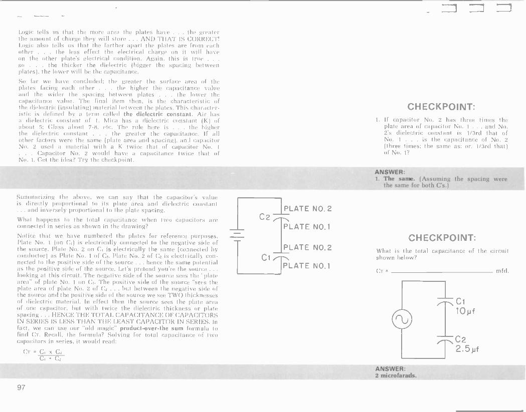
L6
pJw
spejeJoJO!w z
:11:13MSNt/
=13
¿Molaq UMolls 1!n3jl3 ayI jo a3ue1!aede3 lelos ayI s! 1egM
:1NIOd)133HO
(s3 gsoq Jo,' awes ayI aJaM Su!aeds ayI SutwnssF/) awes ay1, i :a3MSNt/
¿1 'ON J° (Imp pjEi1 'Jo :se awes alp :saw!s aaJgs) Z oN Jo a3ue1laede3 ays s! I oN Jo imp pJER. s! luessuoa a!Jl3alalp s,z o¡v pue IoN jol!3ede3 jo eaie aleld ay' saw!' aaay' sey z0N a0l!3ede3 J1 'I
:1NIOdD1O3H3
VON 31b' -11I 13
Z'ON 31did
10N 31t1id 33
Z 'ON 31dicT
1
7p X =
:peaj pinoM I[ sa!Jas ul SJOlt3ede3 oMl Jo a3ues!3ede3 le'ol JoJ Sutnlos ¿elnwjoJ ays 'IIe3a2i '13 pu!J 01 elnutJoJ wns ayI-Jano-l3npojd 3lSew plo Sino asn ue3 aM ''3eJ ul S31213S NI 210.1.13HdHD .LSH31 3H.L NHH.L SSW] SI S312135 NI S210.LI3ddd3 3DNH.1.I3NdHD It/ LO L 3H L 3DN3H ''' 8u!3eds aleld jo ssauNl31515 3!j13ala!p ay1 a3!M' y1!M sng 101!3ede3 auo Jo eaje aleld ay' saas a3Jnos ay1 uayl saaJJa us le!Jasew a!Jluala!p Jo sassaml3!ys OM1, aas aM a3jnos ay' jo apis an!I!sod alp pus a3jnos ays
Jo opts an!IeSau ay' uaaMsaq In 73 jo zoN aseld jo ewe awl(' ay' saas aaanos ay1 Jo apis an!Ilsod ay1 13 uo IO¡v awl(' jo eaJe aleld ayl saas a3Sinos alp Jo apis an!IeSau ay1, 1!13ata s!yI se Sullool
aaJnos ay1 aJnoÁ pualaJd S,lai aaJnos alp jo arms anil!sod ays se le!lualod autes ato a3uay aaJnos ayl jo apis anls!sod ayl os pas3au -u03 /1I1e3!tlaala Si Z3 JO Z oN aIPId 7p J° I'°N awl,' se (aopnpuo3 Aq palaauco3) awes alp Álle3!Ji3ala si uo zoN aleld a3Sinos ay' JO ap!s antleSau agI os pas3auuo3 Cllea!Jlaala Si (ID uo) I o¡v aleld sasodjnd a3uaJaJaJ JoJ saseld alp paaagwnu aney aM legs a3!lo¡v
¿Su!MeJp atll u! uM011s se sa!Jas ut palaauuo3 aje sJoslaede3 o,tis uayM a3ues!3ede3 Ieso1 ays os suaddeg seyM
Suiaeds aseld ayl os leuo!{jodojd iflasjanui pue Iuelsuo3 alJl3ala!p pus Paje algid sy os Ieuo!IJodojd si anlen s,Jo1l3ede3 ay' sey' ue3 aM 'anoge ays Su!z!Jewwns
sulod>laaya ay1 /1J1, ¿eaw ayl sap oN Jo imp a3!Ms a3ueslaede3 e aney pinoM zo¡v Jol!aedep I on! Joll3ede3 Jo legs aalMs >1 e gs!M le!Jalew e pasn Z o¡\I Jos!3Pde3 pue (Supeds pue ewe aseld) awes ays ajaM sjo'3eJ Jays()
lie JI -aaues!aedea ay' JaseaSiS ays 1ue'suo3 3!Jlaala!p ayI Jagli!y NI si aaag alnj ma 31a '8-L Inoge sse10 :g tootle J° (m) InR'snO3 a!jsaalaip e seq ealW 'I Jo Iuessu0 3!jlaala!p e seq J!d suelsuo3 3!J13ala!p ayI palle3 tuja e pauijap s! ails! -Jal3ejeya s!y1, saseld ays uaaMsaq le!Jasew (Su!selnsu!) 3ljsaala!p alp Jo 3!ss!Ja13eJeg3 ay1 s! 'uayl was! Ieu!J a41, anlen a3ues!aede3 ay' JaMOI ays saleld uaaMsag Su!aeds ays JapIM ay' pue anlen a3ue1!3ede3 ay' JayS!q alp Jayso yaea Su!3eJ saseld aqs Jo eaJe aaeJJns ay' ja'eajS ags :papnlauo3 aney aM lei os
aauel!3ede3 ayl aq II!M JaMul ays Isaseld uaaMsaq hu!aeds ayl JaS!q) alJsaalaip ays Jal3!g1 ato OS
awn s! s!yl 'uleSt/ uo!s!puoa lea!Jlaala s,aseld Jayso ays uo aney II!M 5! uo aSJega le3!J'aala ay' IaaJJa ssal alp Jayso yaea woJJ aje saleld ayl IJede JaysJeJ ags leys sn sllal osIR a!SuI 1.L33212103 SI .LtlH.L Nd ajoss II!M Mays aSJey3 jo sunowe aqs JaseaJS alp aney sa'eld ays Raje a.tow ays Ieyl sn slla' 3!1101

INFORMATION As a reminder, let's mention that because a farad is a huge amount of capacitance . . . (a capacitor with this value might be the physical size of a small room) . . . capacitors generally come in values of micro farads (millionths of a farad); and micro -micro farads (trillionths of a farad). A more modern term for the later is "pico farads" . . . meaning the same thing. A 10 microfarad capacitor is normally written as 10 uf or 10 mfd. A 10 micro -micro farad (sometimes written uuf) can he found frequently written as 10 pf (for pico farad).
REFERENCE & DATA CHECKPOINTS
PLATE N0. 2 PLATE NO.2
O.K. We've seen that capacitors in series add like resistors in parallel. - C1 C2
As you might already have anticipated . capacitors in parallel, add like resistances in series. This means that if I have a 10 uf capacitor in parallel with another 10 uf capacitor . . . the total capacitance of the circuit is 20 uf. Look at the circuit in column 2, and let's play our little game of pretending we are the source again. Now, the source sees the following;
T PLATE Il NO. 1
PLATE NO.1
1. The negative side of the source sees CI's plate No. 1 plate area AND C2's plate No. 1 plate area.
2. The positive side of the source sees Ci's No. 2 plate area PLUS C2's plate No. 2 area.
3. The spacing between all these plate areas is effectively ONLY ONE DIELECTRIC THICKNESS.
Therefore, following the concept mentioned earlier that the capaci- tance is directly related to plate area and inversely related to the thickness of the dielectric . . . it is obvious that C total will be the sum of the capacitances. (We have twice the plate area and the other two factors are the same: namely, spacing between plates and dielectric constant.)
Try the checkpoint!
As you can see . . . you simply add up the values of all the capacitances in parallel to get the total capacitance. So, summarizing: CAPACITANCES IN SERIES ADD LIKE RESISTORS IN PARALLEL . . CAPACITANCES IN PARALLEL ADD LIKE RESISTORS IN SERIES! (Just the opposite from the way finding total inductance works ... right? Right!)
CHECKPOINT: What is the total capacitance in the circuit shown?
Cl IC2 C3
-plow 5}tf 5f
ANSWER: CT = 20uf(10+5+5)
98

swqo Si£ '£ swap) S'6L 'Z swyo 65I 'L
SI:13MSNb'
swyo aq pinoM DX Mail alp `anlen aqi Jley aJaM Ing uo!I -sanb u! se awes aqi aJaM rCauanbaJJ aqi ji
swqo aq pinoM DX aqi 'palgnop aJaM
aSellon palldde aqi jo rfauanbauJ ay1 ji
swyo = 3X ¿a/loge 1!13J!a aqi ut uMoys Jol!aedea aqi Jo aauetaeaJ an!I!uedea ayl s! IeyM
JdO'I =3
'£
'Z
'L
ZR-10001=
:1NIOd)1O3 HO
JaMsue aqi laS 01
(65L'0) dot uo Jagwnu paxlJ ato ow! JaMsue Ieyl apintp uaqi aauelluedea aqi saw!l ÁauanbaJJ aqi Áldlllnw s! op o1 IJaI s! leyl Ile Mop; Jagwnu 6SL'0 all laS o1 L ow!
pap!n!p aM anlen awes aqi sfe.tile s! luelsuoa e s! la JOIaeJ ayl auu!S
xJ 691'0 = DX
swqo aauelaeaJ an!1laede3 = DX pue speJeJ u! aauellaedea =
zlJay u! RauanbaJJ = J
I1Z'9 =jtZ
3J11Z
:aJayM
L = (swqo u!) DX
66 1! IaS 01 pasn u!Sol alp
peauaJ pue aJow awos elnwuoJ aqi Su!sn au!IueJd 'Iou {1 ¿auuel!aedea pue /fauanbaJJ ylog 01 :ix Jo d!gsuo!IelaJ asJanu! agl al salelaJ s!yl Moy aas ¿palgnop auuelaeaJ aqi panley seM aauellaedeu uayM pa8ueq3un sJOlaeJ Jaglo Ile gl!M 'osld ¿panley auuepeaJ anll!uedea 'palgnop /CauanbaJJ se leql aa!lou noC p!
¡aueld lewlaap JadoJd aqi JOJ 100 491eM I1113aJJ03 elnwJoJ aqi asn uea no/C J! aas ot lulodnuayu aqi ÁJ,I,
:yl!M nJona o1 Ja!sea s! lell elnwJoJ anoge alp jo uollealJlldw!s d
:s! aauelaeaJ an!1luede3 s! 1! salea!pu! 3 ldlJusgns aqi pue `aauelueaJ sueaw X a.IayM DX wJat aqi ifq paz! -Ioqul/fs) aauelaeaJ an!l!aeden JoJ elnwJoJ aqi IegI 'uagl 'lno suJnl ll
aaue!uedaa 01 pue ÁauanbaJJ glog 01 patelaJ RlasJanu! s! aauelaeaa an!1!3ede3 Iey1 sluawalels anoge aqi woJJ aanpap Ilea!So1 uea aM
suo!Ien!Jap lea!Iewaylew daap ow! SuIoS inoyl!M :£ dais
(MoIJ IuaJJna DV 01 uo!1!soddo Jo) 3DNd.L3t1321 3l11.LIDdddy 3H.L 213M01 3H.1. 31gddH 3V d0 A3N311Ó321.4 3H.L 213HOIH 3H1 :s! 0.104 uo!lanpap Jn0 paauapina aq lsnw MoIJ IuaJJna 01 uo!l!soddo ssal Iflan!IaaJJa
sueaw awll 5581 ut moll uoJiaala wow auuay pa!idde MoIIoJ o1 JapJo u! aSJegustp pue aSJeya Isnw I! JalseJ aqi Jol!aedeu e 01 palldde yd Jo dauanbaJJ aqi JayS!g aq,l, :g dais
ap!sSuole saiou anew pue (uleJq Jnoi) nueg Ifuowaw le3!8o1o!g uMop leyl nJew os
anJ1 s! s!y,1 33NH,LI3Hd1f3 O.I. 1dNO1.L2íOdOild Al3S21Wl1NI SI 33Nd.L3d321 3n1.L13ddd3 spuoM Jaw ill 33Nd.Lyd321 213119IH SNtl31/51 3 33dWS '(aauelueaJ an!l!aedeu Jo) NOLLISOddO MO'I SNd3W O 302íd1 lell Iunpap uea aM uagl aq Isnw MoIJ IuaJJna 01 uoll!soddo aqi JaMol agl pa!Idde 3 uan!S e JoJ Mo11 IuaJJna aqi JaSJe1 alp 'aaulS pa!Idde 3 01 JoI!aedeu win aSJeyu 01 JapJo u! mop 'um IuaJJna aSJequ aJow ay1 'anlen aauel!aedea aqi JaSJeI aqi Iey1 awnsse 01 algeuosea.I s! I! seq JOIIae.dea ay1 auuel!uedeu ganw Mog ol palelaJ ÁllaaJ!p s! l!nuJ!a e u! MoIJ II!n^ legl IUaJJna aSJeyu Jo Iunowe aqi aau!S :I dais
elnwJoJ aauelaea.I an!I!uedeu aqi yl!M dn awoa ueu aM p aas pue 'luaJJna Od sasoddo Jollaedea e ifeM aqi ySnoJyl ÁeM Jno 318o -j 01 ÁJ! s,la aauepeaJ s! palgns ay,l, 3d pue sJol!uedea Su!pJeSaJ Iualgns SullsaJam ue o1 awou aM MoN

INFORMATION
Now then . . . let's relate the Xc and total capacitance concepts into one package.
Remember that capacitors in series added like resistors in parallel, and, capacitances in parallel added like resistors in series. This means when we put capacitors in series the total capacitance de- creases ... when we put capacitors in parallel, the total capacitance increases. Since the reactance (or opposition to current) that a
capacitor shows is inverse to its capacitance value . . . it follows that when we series capacitors, we will increase the total reactance, since CT decreases. THIS SIMPLY MEANS REACTANCES IN SERIES ADD LIKE RESISTANCES IN SERIES. This is true for any type reactance . . . either capacitive, or inductive. It is also true that REACTANCES IN PARALLEL ADD LIKE RESISTANCES IN PARAL- LEL. (In other words . . . the total reactance of parallel capacitive reactances will be less than the least branch reactance).
Try the checkpoint!
If you didn't get the answers, here's a hint, so you can try again until you understand. You should have used a form of the "product over the sum" formula to find the total capacitance in question 1. (CT = CI x C2/Ci + C2) ... and total reactance in problem 4. You should have simply added the series reactances in question 2 ... and added the capacitance values to find CT for question 3. If you missed these . . . recycle yourself through the reading material which is pertinent.
Now we've talked about factors that influence capacitance factors that influence capacitive reactance . . . and we have seen how total capacitance and total Xc can be solved for series and parallel circuits.
THE RC CIRCUIT
Let's move on now to a quick analysis of how current and/or voltage distributes itself in circuits that have both resistance and capacitance. We'll confine ourselves to AC voltage and current . . . since you already understand that in DC, once the capacitor is charged to EA, current ceases (since the capacitor "blocks DC").
Let's look at the simple RC series circuit first.
100
REFERENCE & DATA
TOTAL c = 5yt TOTAL Xc = 200 I1
SERIES C CIRCUIT
Xc2=10011
TOTAL c = 20 Pf TOTAL Xc = 5011
PARALLEL C CIRCUIT
CHECKPOINTS
CHECKPOINT:
Xc1 =30011
Xc2=1001l
1. What is the total capacitance of the circuit shown above? uf.
2. What is Xc total? ohms.
3. What is the total capacitance of the circuit shown below? uf.
C2 15 pf
Xc1= 300f1 Xc2=100II
4. What is the total Xc of this circuit? ohms.
ANSWERS:
1. 3.75 uf 2. 400 ohms 3. 20 uf 4. 75 ohms

(anley pjnoM asneaag) aseaaaaQ 1 saaaSap sb £
saaaSap st ueyl aaleaa0 peal L
aSa3MSNtl
¿awes agf u!ewaa JO
aseaaaap 'aseaaau! alSue aseqd aqi pinoM 'palqnop s! aoj!aedea alp Jo anlen ay1 J1 b
saaalap ¿saaaSap 06 JO saaaSap 46 'saaaSap
oaaz ifq palldde aqi yjlM aseqd jo lno aq juaaana j!naala aqi pinoM 'palqnop sl H JI S
¿saaallap 46 ueql aallews ao aajeaaS aq alliue aseqd I!naa!a alp ll!M Z
ilOi=Zi Zi
)109=DX
¿Melton pa!Idde aqi lei JO peal Molaq uMoys I!naa!a aqi aoJ luaaana IIIM 'C
:1NIOd)103H3
3SVHd NI
t --- d3=v3
(3 SOV31 1
33 v3
'3SVHd 301n0e06) 1
oSb=319N1 3SVHd 3X=lJ 111101,113 S3IM3S
v3 1. _
1.01-
esaan app pue ,lX aaqSly sueaw a IlewS aagjo (pea oi asaanu! aae Áag1 imp
aagwawag pasnJuoa aauefaea21 anlltaedeD pue aauej!aedea jaS oj luapnls aoJ aoaaa uOwwOa e s! I! 'sf!naa!a a21 yIIM Sulleap uayM
HOf1OH.L .Lf10 HaLHM luaaana lelol uo laaJJa IsajeaaS aqi aney !pm aaoJaaayj j! ySnoagj Juanita jsaleaaS alp aneg II!M juaaana ol uoll!soddo 'seal aqi yj!M gaueaq ayl, :s! as!waad aqi
pa!jdde 3 pue luaaana I!naa!a uaaMlag ajSue aseqd ayf pue juaaana l!naata uo papa aajeaaS aqi aneg II!M luauod -woa llu!paelJaa 's! jey,L anal sl sl!naa!a 'RI ul pasn (juaaana I!naa!a óuloaeóaa) aslwaad a!seq awes alp 'sj!naata a21 lalleaed ao3
Iu!ud)Iaagp jxau agl /III pu!w u! Slue.] anoge aqi Su!daaH
' ' HOv.L'1on '.LN322If1a u! aSuega e sasoddo aolanpu! ue
u! aSueya e sasoddo aoj!aedea agl aauassa tal
(uew 33I aq l Il3 pua!aJ pp) ano) luaaana speal aSejlon lump iN ay! ao,4 aSejlon speal luaaana . l!naa!a DH aqi aoJ leyl jaeJ ayj u! sail I!naa!a '121 ay' pue 1!naa!a DH ayj SulzA'leue uaaMjag aauaaaJJlp Ra)I ay,l
salj!juenb lea!alaala aqi Jo sd!ysuo!jelaaaalu! aqi puelsaapun dlay 01 wayl asn ifldulls-suleallelp aojaan alp az!aowaw 01 iCal l,uoQ
saaajlap 06 pue saaaSap
p Jo sawaajxa uMj ayj uaaMlag aaagnnawos aq II!M sllnsaa aqi uaqj juasaad aae :)X pue H qioq J! saaaSap oaaz aq
pinoM alSue aseqd atlj anljs!saa Álaand aaaM Imaala aqi J!
saaaSap 06 aq pinoM alSue aseqd ayj '(luasaad aauels!saa ou) anlj!aedea Alaand aaaM Ilnaata ay; J! asneaag srgl apnlauoa iIII'a)!Sol uea am jeyj Ileaa2í v3 gj!M aseqd Jo Ino saaaSap sti uetíj ssal aq II!M I uayj ;)X ueyl aaleaaS sl H JI 121
uey1 s! :)}¿ aajeaaS yanw Moy uo Su!puadap saa.lSap 06 pue si uaaMjaq aaaqMawos) v3 yI!M asegd jo Ino saaaSap Sb uegj aaoW aq IIIM juaaana 1!naa!a aqi '2J ueyj aaleaaS sl a)( JI '' pa!ldde 3 yj!M aseqd Jo lno saaaliap 917 aq IIIM juaaana I!naa!a aq) lenba a,:e :)X alp pue H ayj JI '1I1132113 531213S 3H.L 2iO.l 31121.L SI SINHS 3H.L aolaeJ Su!Iloajuoa alp seM juaaana DH aqi of swyo u! uoll!soddo Isajeaali aqi peg ga!qM luauodwo3 aq! (aolanpu! pue aols!saa) j!naa!a .121 sa!aas aqi u! leyj aagwawag

INFORMATION We can conclude then that if R = Xc in a parallel RC circuit
. . . the circuit phase angle will be 45 degrees. If R is greater than Xc . . . then more current will flow through the capacitive branch . . . and the circuit will act more capacitively .. . hence, phase', angle will be between 45 and 90 degrees. If Xc is greater than R . . . then the opposite is true and the circuit phase angle will be less than 45 degrees . . . and be somewhere between 0 degrees (a pure resistive circuit) and 45 degrees (a circuit where R= Xc. )
To see if you understand these principles . . . try the next checkpoint.
Trust you got those answers correct. If not . .. here's the thinking you should have used. For question 1 . . . we can make a general statement which is true in virtually all cases . . . If there is any "net" capacitive reactance in the circuit ... the resultant circuit total current will lead E applied by some amount. THIS IS TRUE FOR BOTH SERIES AND PARALLEL RC CIRCUITS. (By the way . . . if there is a net "inductive reactance" in the circuit . . . the voltage will lead the current by some amount). It may help you to remember the concept that inductors oppose changes in current . . . thus voltage leads . . . capacitors oppose a change in voltage . . . thus current leads. For question 2 . . . since Xc was greater than R . . . then there will be more current through the R branch (since E is the same across both components in a parallel circuit) . .. hence, the resistive branch has more effect on total current . . . therefore, the total current will lead Ea by less than 45 degrees. The thinking on question 3 is: if capacitance were decreased . . .
then Xc would increase (remember the inverse relationship?). If Xc increased . . . then the current through the capacitor branch would decrease . . . and the resistive branch current is even more in control of IT ... hence the phase angle would decrease.
REFERENCE & DATA Ic
Ic
Ic
IT
IT
IR
IR
or EA
CHECKPOINTS
CHECKPOINT: 1. Refer to the circuit below and determine
if the circuit current leads or lags Ea. IT Ea.
Y,c=20K
EA 2. Will the phase angle be less than 45 de- li
grees . . . more than 45 degrees . . . or exactly 45 degrees?
1.1 EA IR
3. If the value of capacitance were decreased . . would the phase angle increase, de-
crease or remain the same?
4. In order to achieve a phase angle of 45 degrees for this circuit, would the applied FREQUENCY have to be increased, de- creased or kept the same?
ANSWERS:
1. Leads 2. Less than 45 degrees 3. Decrease 4. Increased
102

lI
13
1:13H1t1a lna `3x+1:i 30 N011.IOOt1 31-11
nbn03 ION 5300 1Z
3J yJ1/Z = 1X 65L0 = DX
... +13 = 8,3 ¡allured JOJ 1V1013
ZZ +11 zri x'i = S.rI
Ialleaed JoJ lvJ.on
73 + '3
saiJaS JoJ wror.y '3x'3=5,3
sairag JoJ ivr.or0
S21O1I3VdV3 S210.L3fIaNI
Za+12i=12i
+ IItM DX ( f ) saseaJaaQ aauellaede3
} 1I!M DX ( + ) sasearaul aaueliaede3
} II!M TX ( f ) saseaJaaQ aauelanpul
1 I1tM 'IX ( + ) saseaJaul aauelanpul
/ IIIM DX
f11lM "IX ( f ) saseaJaaQ RauanbaJd
/ Wm DX
1 1IlM TX ( +) saseaJaul Rauanbaad
.L1f1S32H 213131AIV2IVd 9NI9NVH3
£0 l '33NVa3dWI 3H1
Q311t10 SI MOgd .LN32121f13 01 NOI.LISOddO .L3N ZV.LO.L SIH.L MotJ IuaJJna oI uolisoddo llqiyxa ¡¡iM 'Inoge Sume; uaaq aft am sluauodwoa ay; jo He JO 'Rue Sululeluoa IlnaJla atuoJlaa¡a RaV
Meq s,wyO oI are 2l pue '3 se (eluawepunJ se sl ya!yM slmaJla 3V u! Idaauoa e ol noR aanpoJlut mal 'any ;y812í (aauelaeaa pallea) sJolanpui Jo saoliaedea JOJ pue (aauelstsaJ patlea) sJOISIsaJ JOJ Mo11 IuaJJna ol uoi;lsoddo jo swyo ay; Inoge panic; aney aM aauelanpui Jo/pue aaue;laedea 'aauelslsaJ Sululeluoa sl!naJl3 3H ui sdlysuoilelaJ aSe;lon pue luaJJna Inoge panic; aney aM
30Ntla3d W I 30 1d33NO3 3H1
uollewJolu! Ran ay; ;08 an,noR lJeya alp uo sluawale;s ay; puelsJapun noif JI wJoJ IJeya
aldwls e ui o1u! alseg siy; lie Ind aney aM s;daauoa leraua8 ay; R¡IealydeJB aleJ;sn¡l! 01 pauo!luaw seM ;fly RJessaaau IOU si slsRleue Jo;aan ay j, Isal 33,4 JnoR JoJ seinwJoJ oX pue ay; mom; ;snw no,t, ;noqe Supiie; uaaq an,aM IeyM jo sldaauoa lerauaS ay; Ia8 ;seal le 01 lselsnylua sa!uoJlaala ue se noR 01 inJdlay aq ;pm I! lug saauelaear pue aauellaedea 'aaue;anpu! Su!pJeSar any RJoayl u! Rl!neay R;lard noR uo 1! p!el an,aM
a;a 'alSue aseyd ay; 'aauay IuaJJna IlnaJla ay; (aaJSap JaSJet e o;) SI0J11103 yauerg anien
a!wyo Jallews ay; sip -tarp ani;aeaJ pue anllslsaJ ¡allered ul sloJluoa anted\ JaSJet ay; aauelaeaJ
pue aauelslsaJ Sulute;uoa sIlnaJla saiJas Ui ley; Idaauoa ay,l, Z D pue J o; leuollrodord RlasJanu! Sulag a}( jo ;daauoa ay j, i
:puelsJapun oI RJI pinoys Inc; stle;ap weJSelp Jolaan ay; lie inoqe RJJOM I upinoys noR ley; Res s,la¡ 'arow nu()
(a)( pus j uaaMlaq dlysuolleiaJ asranu! ay; JagwawaJ 'u!eSe) RauanbaJJ ay; aseaJaui ;snw aM 'slgl op oI Japro ul ?j yElm ¡enba Ii HS 01 a}{ asearaap 01 paau aM
ueyl JaleaJB Mou si a?{ a.iu!S aX aSueya saop Inc; a aSueya lusaop RauanbaJJ SulSue43 ienba ay o; aney pinoM aX pue g saaJSap qb jo alSue aseyd e anatyae o; Japro u! boN 103

INFORMATION Impedance then, is the total opposition the source "sees" to current flow. Another way of stating this is to say that the ratio of Er to IT is the impedance . . . or opposition to current. Ohm's Law states that ohms of opposition equals E/I. Because the presence of any reactive component (I. or C) in an AC circuit causes circuit current/s to be out of phase with circuit voltage/s ... it is logical to expect that we cannot just simply add up the reactances and resistances to find total circuit opposition (impedance).
For our purposes . . . it is only necessary that you realize that the circuit impedance (commonly represented by the symbol Z) equals the circuit voltage divided by the circuit total current. The only difference between Z and R is that Z is made up of a combination of R and X (reactance). For PURELY resistive AC circuits . . . you can deal with R -total as always. For PURELY REACTIVE circuits (All C's or All L's) you can deal with the reactances just like you do resistances to find total opposition. When both resistive and reactive components are present in the same circuit . .
it takes vector type analysis, or other math to analyze . . . but in ALL cases . . . the total opposition equals E applied divided by I total.
Try the checkpoint!
How'd we get those answers? Well, Z = h/I ... thus. 100v/ 10 mA = OK ohms. If frequency is increased ... then Xc will decrease (look at the formula). If Xc decreases and R stays the same . . . then it is logical that the total opposition must go down. This brings about a
very "nifty" general statement regarding circuit total resistance and/or total impedance.
NO MATTER WHAT KIND OF CIRCUIT .. . SERIES, PARALLEL OR SERIES -PARALLEL . . . IF ANY ONE OR MORE OF THE ELEMENTS CHANGES VALUE OF OPPOSITION ... THE TOTAL CIRCUIT OPPOSITION WILL BE CHANGED.
REFERENCE & DATA
ZT = ÍT IN ALL CASES
R2 RT = RI x R2
R1+R2
ZT DOES NOT EQUAL
R x Xc R + Xc BUT RATHERIT
CHECKPOINTS
CHECKPOINT: 1. What is the Z (impedance) of the circuit
shown below? ohms.
I=10mA
EA= 100 V
2. Would the circuit impedance increase, de- crease, or remain the same if frequency were increased?
ANSWERS:
1. 10K ohms. 2. Decrease
104

aseaJaul C aseaJnul 'Z aseaJnaQ
:Sa3MSNtl
¿awes ay) ulewar JO aseaJnap 'asearnul z Ilnarla ay) pinoM 'anlen ul palgnop si Zg JI E
¿awes ayl mlewaJ JO aseaJaap 'aseaJaui Z ay1 pinoM 'anlen ut paseaJnui sl S JI Z z1
¿awes ay) uiewaJ Jo asearaap asearatp z IlnnJla ay) pinoM pasearaap sl pal ay) le uMoys llnaJla ay) JoJ ;Mellon palldde jo rinuanbaJJ ay) JI
:1NIOd)133H3 I.
aseaJnaQ £ aseaJaul Z aseaJaul [
:SlI3MSNt!
¿awes ay1 ulewaJ JO aseaJnap 'aseaJaul Z IlnnJla ay) mom anlen ul palgnop sl JI S
¿awes ay) ulewaJ Jo aseaJnap 'aseaJaul Z ay) pinoM anlen ul paseaJaul Si 2l J¡
¿awes ay) ulewar ro aseaJnap aseaJaul Z )lnaJla ay) pinoM paseara -ap sl ~Hon palldde jo ÁauanbarJ ay) JI
:1NIOd)133H3
ZH 000L
901.
¡au() sly) ir) Mo¡v
¡Iutodvaya ay) ul alipalMoul siyl ,ilddd
N011.3:I2114 3INHS 3H.1. aliueya !pm uolllsoddo lelo) s,)ln:)Jla ay) 'saliueya uolllsoddo jo anlen awry!! s,luawala Aue Ji iml/1eS uaag an,ann IeyM liulzlJewwns IlnaJla aAIIsISlJ Álarnd e s)l asJnoa jo 'ssalun palueya Iuawala ay) se anen awes ay) Ay a11ueya 'pm uol)isoddo lelo) ay) ply) liuplulyl olul palooJ ay I,uop rauepadwl IlnaJta ay) aliueya IIIM (panlonul are sIuauodun09 ani)aeaJ aJayM) palldde AauanbaJJ ay1 -;ulliueya ro (1 ro '21) )uauodwoa e JO amen ay Iulliueyn 'sn41, aseaJnap 'pm (sllnarw Dd JoJ Z) uolllsoddo lelo) llnarta ayl " awHS ay) ulewaJ s)uawala ray!!! He apyM saseara -ap rolllsoddo Jo anlen s,)uawala UP Jl 'ilasJanuoD aseaJaul lpM aauepadur ¡war !a wpm ay) paseaJaul si Iuawala auo JO uolllsoddo ay) ply !mien ul )uelsuoa ulewar SlUawala Jay)o ay) He JI

INFORMATION
THE RESONANT CIRCUIT
Since we have now studied inductance, inductive reactance and
RL circuits . . . capacitance, capacitive reactance and RC circuits . . let's put all these components together and study a very interesting phenomonon called Resonance.
We'll start with a series RLC circuit and the phenomenon of series resonance.
Look at the circuit in column 2 and note the values of reactances and the resistance value.
Because XL (inductive reactance) and Xc (capacitive reactance) affect circuit current and voltages in "opposite ways" ... some interesting things happen in this circuit. In effect . . . the XL and the Xc cancel each other out . . . so the source sees a circuit where the only effective limitation on current is the R value within the
circuit. (This is assuming a perfect coil with no resistance and a perfect capacitor, with no resistance . . . in which case they would perfectly cancel.) Assume the theoretically "perfect" condition ... what would be the current in this circuit?
Well, using common sense and Ohm's Law . . if the reactances cancel each other, the circuit impedance is equal to the R value of 1K ohm. Current = voltage divided by resistance (or impedance) ... thus 10v/1K = 10 mA of circuit current.
That was easy wasn't it? Nov, here is where the fun begins. Since the current is the same through all parts of a series circuit . . . then the 10 mA of current must be passing through the Xc and the XL as well as the R. Using Ohm's Law to solve for voltage drops we find that 10 mA times XL of 10K = 100 volts . . .
AND, 10 mA times Xc of 10K = 100 volts. Wow! With only 10 volts of E applied, we're getting 100 volts across the coil, and 100 volts the capacitor ... THAT'S RIGHT! The secret is that these reactive voltages are equal. . . BUT OPPOSITE IN PHASE . . . thus, as
far as the total circuit is concerned EA is dropped across the
R, and the reactive voltages cancel each other. Nevertheless, there REALLY IS 100 volts across each reactance, individually. If we
were able to have a meter (voltmeter) which did not "load" down the circuit ... we could actually measure that voltage. This unusual circumstance occurs in series resonant circuits. In fact, one way of judging the "Quality" of the reactive components is to note how many times greater their voltage drops are than E applied. This is called the Q of the circuit. It's obvious then that this ratio is directly related to how many times greater the XL or Xc:
is, than the R.
106
REFERENCE & DATA CHECKPOINTS
EA= 10V
I=10mA
1K ER=IxR=10mAx1K=10V XC=10K EC= Ix XC=10mAx10K=100V
XL= 10K EL= Ix Xt_=10mA x 10K=100V

{asellon palldde uanlS e yIIM I aamol sueaw z raySly) JaMo7
"OM 'L (swqo Noe Jo aoueloear anllonpul Hu e sI arayl ro DX ayI pue alp uaaMlaq ?(OE Jo aouaraJJip e SI arayl laa;Ja ul os
>IOL ro 'palgnop seM Rauanba.)J uayM >IOZ Jo artier) IeulSlro SI! Z/L 01 IuaM pue palgnop ÁuuanbaaJ uayM xOb oI
x0Z won palqnop asneoag) swyo x0E '9 scull() x06 'S
OZ 'b slIon OL '£
sllon 00Z 'Z d OL 'L
:Sa3MSNt/
¿aoueuosar le seM II se awes alp JO raMol 'raySly aq luarrna Ilnona ay' pinoM
¿aoueuosar fe seM II se awes alp ro raMol 'raySly aq (z) aouepadwl Ilnu.tla ayl pinoM L >IOZ=1X
aoueloear finarla Iau 041 aq PInoM IeyM 9 >402.0X
swyo
¿palgnop si ÁouanbarJ ayI JI
¿palqnop sl tfouanbarJ JI aq X Plnon^ legM
b aulwrafaa
Ng aulwralaQ
13 aulwrafaQ
l aulwrafaQ
'£
'Z
1
:Z uwnloo ui llno.Ilo ay! 01 SulrraJa2l
:1NIOd)103H0
LOL
sasodrnd ifpnls-)Iolnb roJ Iinana luPUOsar sauas e Jo SUIISIdaIUPdP,yU alp Jo ifJewwns e noA anlS II,aM uall paniaap araM Rall Mol pue SraMSUe all ysnoryl um! >Iolnb e anel S,laq
IulodyIoayo all wroJrad slinana Iueuosar salras Sulpresar sfulod u;ew ayf aney noif ll aas s,Ia-I xO
aauepadwl all aulwralap uayl pinoM all 41!M salras ul 'Imp sauueloear oMI ayl uaaMlag aouaraJJip ayI aq wpm llnorlo ayl U! 33NH.LDH321 .L3N aq.L 'llnaaln -321 ue JO 'IinorPo 3 ue raylla Jo lualenlnba ayI aney uayl pinoM aM pue raylo alI laoueo ueyl arow wpm ralears seM ranalolyM snyl :)X lenba rasuol ou pinoM ¿asueyo pinoM IP.lM MoN '.LNHN -OS321 3g .LON uayl pinoM llnorlu ay,I, 'papa malo yoea laoueo snyl pue Ienba ÁlfoaJrad aq raSuol ou pinoM pue 'aSueyo pinoM sauueloear ayl 'llSlr s,legy aSellon palldde all Jo ifouanbarJ agI JO 1 'D raylla Jo anlen ayI paáiueyu am JI uaddel pinoM IelM
luarrno alp Sululwraiap pue Sulliwll aaaM saoueluear all JI uell anlen ralea.iS yonw e Jo sl pue 3DNHNOS321 S31213S IV WIIINIXHW SI LN32I2I(l SI ANNA. ' ' ' 21 ifg /fluo paflwll st Iuarrno linoalo alp asneoaq algissod sl aSellon JO uolleolJlusew sly.l, 'OL =
x1/x01 ' aaMsue awes alp sn sanlS elnwroJ ay! Suls¡7 01 = 01/001 = Ó snyl SIIon 01 SeM palldde 3 sllon 001 adaM saSellon luauodwoo anlloear ayI aldwexa rno ul v3/13 ro v3/33 slenba osle Itnorlo IUeuosar sayas e roJ Ó imp sueaw slyl palldde 3 Di olfer awes sup are sdoip Mellon aniloear alp uayl saoueluear alp pue g alp lsnoryl awes alp sl I alp asneoag 2í/ -Ix = llnorlo lueuosar saWas P, roJ b SprOM raylo uI

INFORMATION For question 1 ... I = E/Z. In this case Z=R because the reactances cancel each other, since they are equal in value and opposite in type. I = 10v/1K = 10 mA.
2.-EL = I x XL = 10 mA x 20K = 200v
3.-ER = I x R = 10 mA x 1K = 10v.
4.-Q = XL/R (or EL/EA) = 20
5.-XL is directly related to frequency and/or inductance. In this case L stayed the same and frequency was doubled . . . then XL would double. (Remember Xi. = 2 ft. formula?) Since the 2 pi and the L were constant, but f doubled . . . the product, or answer is twice as great.
6.-Explanation given in answers column.
7.-Since the circuit impedance would now be made up of 1K of R and 30K of "left -over" XL . . . rather than just the R, as at resonance . . . obviously the circuit Z would increase.
8.-Since circuit current is inverse to circuit impedance, and impedance increased ... then I must decrease.
In column 2 we have put a little "Summary Chart" for series resonance. Try to learn these key facts!
Moving on ... let's talk for a few minutes about Parallel Resonance.
Again . . . resonance (for our purposes) occurs when Xt. = Xc. We will only consider the theoretical "perfect" coil and capacitor (no internal resistance). In a practical sense, all these components are not perfect . . . but the characteristics we mention are true in a
general sense for parallel resonant circuits . . . and you need to know these "generalizations" for your FCC test.
Look at the circuit in column 2. If XL really does equal Xc . . .
then both "branches" should have equal currents . . . because in parallel circuits E is the same across all branches. Each branch current = E/opposition in ohms. In our example I = 10 volts/10K = 1 mA for each branch.
108
REFERENCE & DATA CHECKPOINTS
CIRCUIT CHARACTERISTICS AT SERIES RESONANCE
1. XL = Xc (net reactance = 0) 2. Z = R (thus Z is minimum) 3. I = maximum 4. Circuit Phase Angle = 0° 5. EL or Ec = Q times E applied 6. Q = XL orXcp EL Ec
EA= 10V
XL=10K

s!gl an!! now PInoM waoJ -aneM alp 'sassol I!na,ila ou aaaM aaayl JI
:YIN¿Z ao :Mr` aJ
[ 691.0
ASaaua aqi dn asn I!na.1!a u! sasso¡ I!lun .tano pue aano sleadaa aouanbas anogy
leu!Swo woJJ uo!l
/ -oaa!p aIlsoddo u! J ySnoay{ saSaeyostp D
013 Ál!sie¡od al!soddo ' o{ O Su!Saeyo pue dy\ig Su!onpu! 'sasde¡
-loo pin I!oo 'paSaeqo`!P AllnJ s! O uayAri ySno.iyl saSaeyostp 3 y31!Ms uadp
an¡en oI saSdego O yol!Ms aqi asol0
r---------
W? GAMau!S PedweO,. Od 3AVM ( ((
L - - -- ----!
(l!na.no u l Ol Jo ap!slno) aaanos woaJ luaaano = au!li
aut¡I aut¡I
Iao I-b 9
I!noa!ai b = I S
00 = alSue asegd b wnw!u!w = ¡ g
wnw!xew = Z Z
DX =1X i
30NVNOS3a 1311VaVd E103 S011SIli31OV tiVHO 11f101i10
60l
:s! II riouanbaaJ s!y1 Su!pu!J aoJ PinwaoJ e s! aaay,i, 3X = X aaaqM osle st riouanbaaJ Slip aa!iaea pawls se puy ifouanbaaJ iueuosaa aqI palieo s! san000 oIa 'plalJ o!aloala s,aol!oedeo alp 01
. . o!IauSewoaloaia s,i!oo ayI ol
. . . o!aloala
saolloede3 ay' woaJ riSaaua Jo aXueyaxa purlieu sup tlu!gM le ifouanbaaJ aq,i, 1!n3a!3 aqi u! (sluauodwoo JO ssol En 01 anp sassol way) sassol, aqi aoJ dn anew oI gSnoua s! ap!noad o{ spaau ao.mos aqi riSaaua riluo aqi asano3 Jo nUel ay 01 aaJnos 0t/ ue goelle riluauewaad aM uayM aneM auls Od aeiliwPJ ano si I!nol!a nu0i s!yI ssoaoe saeadde imp aSellon aqi ySnoua ÁISuilsaaalul uo!Iua.i!p al!soddo aqi u! awii s!yl lug aS.rnyosw u!eSe il!M aoitoedeo aqi pasdel¡oo seq Pla!1 s,I!oo ayI aalJb sleadaa ssaamd aqi uaqi pup 8 IPyI 01 JoI!uedeu aqi anew Il!M ya!yM l!o:, ayI ssoaoe ril!aeiod a{lsoddo lo aSelion 11:!3npu! sasdelloo pia!J s,l!oo ayI paSaeyos!p rfllnJ SeM a011:)Pde7 aqi uayM uagi l!oo dill 100(10 pialJ o!¡auSew aqi dn PI!nq PInoM yo!yM I!oo ayI suoaloala sI! aSaegos!p pinoM aoqoedeo aqi ya!yM Ie riouanbaaJ leanleu ayI s! I! 'l!nai!o nuOl., lalleaed alp aod sueaw 1.11.191 legl IeyM rilloexa noif 01
uw!eldxa Inoyi!M aaueuosaa waal agI pauo!{uaw aM 'rilieivap!oui
aanaiegM ao p!nbii saaois nuel e se qanw riSaaua leo!alaala aaols sluauodwoo an!Ioeaa asaqi imp 13eJ aqi woaJ pan!aap s! Ii s!naa!o J'I !alluded ol auuaaaJaa u! paso rflluanbaaJ s! l!naa!a nuel mat
3 ay,i, laeya riaetuwng ayi u! noA aoJ waai Mau e pauolluaw aM
Isa{ aqi aoJ sioeJ rian asaqi meal aoueuosaa Ial¡eaed aoJ suo!I!puou I!noa!o pazuewwns an,aM aoueuosaa le wnwtu!w aq pinoM luaaano ay1 lug Iuaaano jo uo!Iellaoueo papad aq lou pp -tom aaay{ aouay papad loll ale sluauodwoo aqi 'aJ!I leaa ui K!u!Ju! = aauels!saa aI!u!Ju! jo aouepadw! 1!n3a!o e pia!R p¡noM uo!I!puoo I!noa!o ¡eo!Iaaoayl s!gi 'uayl o!Sol ,cg oaaz aq pinoM (an!loeaa riiaand aaaM Inq aoueis!saa ou peg sluauodwoo J!) Iuaaano I!noa!a {au atu, iaoueo riayl ailsoddo pue ¡enba aae sluaaano asaqi aou!g (uo!loaa!p allsoddo alp u! JO) ti gI!M aseqd Jo 'no saaaSap 091 s! youeag aol!oedeu ag{ gSnoagl Iuaaano ay1 {eqI sueaw s!gy saaaSap 06 rig aSel¡on sSel Iuaaano 'l!oo e aoJ 'saaaSap 06 Rq aSellon speal luaaanu 'aol.!oedeo e aoJ ley' ¡team

INFORMATION Another way of looking at the resonant frequency is to imagine that you are pushing a swing with someone in it. If you push "at just the right moment", the person will continue to swing at the same level. If you push at the wrong moment . . . you will change the level of the swing . . . or may even slop it. The "frequency" at which you push, is the natural, or resonant frequency of the swing. In the electrical circuit . . . the resonant frequency is the frequency at which new energy "injected" into the circuit will sustain the level of voltage and current and overcome :he losses. It's not too important that you know any deep theoretical knowledge here . . . but if you have the concept that there is one natural frequency . . . the resonant frequency . . . for any given LC combination.
Try using the "resonant frequency formula" on the problem. HINT:
fr = 0.159/ C Where fr= the resonant frequency in Hertz.
L = inductance in Henrys C = capacitance in farads.
Watch out for your decimal places. Good luck with the checkpoint!
By the way, you can find the resonant frequency of a series I.C. or RLC circuit using the same formula.
THE ELECTROLYTIC CAPACITOR
Time now to move ahead from the DC and AC circuit theory portion of study to look at several components you will need to have a basic knowledge of for the FCC test. These components include some information about Electrolytic capacitors, semicon- ductor diodes (including Zener diodes), basic vacuum tube infor- mation and transistors.
You have already learned that a capacitor is composed of conductive plates separated by a non-conductor material, called the "dielectric". There is one particular type of capacitor that is unique; you need to know some of its characteristics. This is the Electrolytic capacitor.
110
REFERENCE & DATA CHECKPOINTS
"Photo Courtesy of Centraleb, the Electronics Division of Globe -Union, Inc."
L 9Hy
CHECKPOINT: Solve for the resonant frequency of the cir- cuit shown in column /.
fr Hertz.
ANSWER:
fr = 53 Hertz.

111
1:13N3Z 03StlI8 3S1:13n3l1 '1)IISI.11)13F'.JL'yJ a`fellon IUelsuuJ slyt lali al JapJo u! Seim al!sodclo ac!! alejado ol
3atlW aJe sJauaZ apoue oI apoyleJ wOJJ moll SuoJlJala os paleJadO aje sapolp lewJO¡v uollJaJ!p asJaAaJ ayI U! Al!neay slJnpuoJ apo!p ato pue u,wopeaJg JO agauelene s! aJayl aJagM lu!od e
sawoJ wail! paseaJJu! si apuyleJ pue apoue uaaMlag aJuaJaJJ!p - lellualod ay! sV aJ!Aap sp.!! Jo aliesn leulJou ayI aney am 'apoyleJ
ay! Uo pJeld S! 111!)11010dan!t!sod e pue apoue ayl uU()paJeld s!
T+ lellualod aA!leliau e uayM a! pase!g asjanaJ st apolp snit uayM
30010 113N3Z !yS!J le uMOgs s! app JauaZ ayI JoJ logwSs ayy
aJuajaJa.e aSellon e JO Jo)e1nSaJ aSellon e se pasn ualJO s! I! 'uuseaJ snit JUd Sa1JeA I! ySnoyl IUaJJn:) ay! ySnotll uana Jlasl! ssoJJe doJp aSellOA IUelsuoJ SJan e sutelu!ew I! (apo!p lewJou ay! 01 paJedwoJ) uo!1JaJ!p asJanaJ ay1 u1 JIas1! tOno1yI luaJJnJ ItullJnpuoJ SIJelS I! aJuo eyl s! 3!Is! -JalJeJegJ u!ew si! asneJag aSesn spU!J luauodwoJ sigI, apolp JauaZ ay¡ s! Ia.S passnJslp Iou anal.' am ap0!p Jo¡JnpuoJ!was adSl au0
3a01a 1z13N3Z 3H1
AJI!nJJ!J agnl wnnJen JoJ s1!nJJ!J Alddns JaMod ut Alu!eyAl Jta sJo!!JedeJ ssedÁg 'sJalltJ Slddns JaMod :apnlJu! aSesn jo saldwex3 S.L117021I0 0a u! aJuellJedeJ Jo sanlen 411ly Jo paau s! aaayl JanaJatlM uo!IeJlldde pulJ 'pawn ua1Jo aJe Saql Se 'sJlISIoJlJa13 Jlasl! sAOJlsap pue dn swag !no sIJogs It Sens SUOJM agl JOIIJedeJ ay! ySnoJgl passed s! IuaJJnJ uayM J!JlJala!p pinbll!was agI u! panlonut AJIslwal.lJ ay!. 01 anp s! sno!JsuoJ AI!Jelod s! JoilJedeJ adSl slyt uoseaJ ayy
a:IAO21.LS3 liu!aq jo ssa:)OJd ayl u! si I! al!gM Jopo Aa)lows SUOJIs e !no !al pue dn 11aMs ¡seal Ie JO dn molt! Sew II i.MOd ' saóueyJ aSelloA pa!ldde Jo Sl!Jelod ay! aJatlM 1lnJJ!J JV ue ow! It Ind 01 /Ill Jo SpJeM)lJeg 1lnJJlJ ayl ow! !MO Ind noS ji anllexau ag! st yJ!yM pue apls an!I!sod aqi s! JollJedeJ ay! jo peal yJlyM Mou)l nuA ley! os panJew aje SayL AVM 3NO IlnJJlJ 0a e u! palJauuoa aq Atila ueJ It win sueaw ley,l, S1]OI0SNO0 A.IJ21V3 -Od s! I! ley! s! JollJedeJ JtIAIoJIJala ay! Su!pJeSaJ JagwawaJ 01
31lS1Jal32Je43 Iueljodw! AJBA V Su!wjoJ palleJ s! ssaJoJd le!I!u! will IJeI ul JoI!JedeJ ay! al palldde Allelllu! S! aSetlon e
uayM uO!!Je leJlwayJoJlJala yonojyl J!JIJa¡a!p lenlJe ayl swJoJ ley! sateld ay! uaaMtag le!Jalew pinbll!was e seq pue saleld SI! JoJ lloJ-wnulwnle sasn JollJedeJ adAl sly,L ZZVWS A213/1 s! ssaulJ!y! J!JlJalatp ayt Iey1 s! sty! JoJ uoseaJ Uiew aq,l, az!s si! JoJ aJuel!JedeJ JO IO1 e sap!noJd I! Imp SI SJ!Is!JaIJeJeyJ San SI! JO auo

INFORMATION Let's see if you have picked up the most important points regarding the Electrolytic capacitor and the Zener diode. Try the checkpoint!
VACUUM TUBES
Moving on now . . . let's give you a quick refresher regarding vacuum tubes. You remember that in the Novice chapter we
talked about the diode and triode tubes. Here, we'll briefly review and then we'll add basic knowledge regarding the tetrode and pentode tubes.
At this point, it may be good to "flat out" state a law of electricity that we have implied over and over again in our discussions . . .
but have never really said in so many words. The "law of electric charges" is that LIKE CHARGES REPEL . . . UNLIKE CHARGES ATTRACT.
112
REFERENCE & DATA CHECKPOINTS
CHECKPOINT: 1. Two key characteristics of electrolytic ca-
pacitors are: they have (high. low) capac- ity for their size? they (can, cannot) be connected into AC circuits?
2. True or False? Probably the most common usage of electrolytic capacitors is as power supply "filter elements".
3. The most important characteristic of the Zener diode is (hat in operation it has a
relatively constant (voltage drop across it; current through it)?
4. This characteristic becomes evident for the Zener diode when the voltage applied to it reaches a level to cause "breakdown", "avalanche", or, its "zener" point. True or False?
ANSWERS:
1. High capacity for size; and Cannot be connected into AC circuit.
2. True 3. Voltage drop across it 4. True

300HIV3 01119 1O1I1N00
ONt! 314'ld N33M138 30Ndl10tldtl0 3001110313831N1
d60
31V1d
Ell
sal3uanbaJJ Jay AJ!Idwe oi AJI noA se Jam()) pule JaMol malt p!Jx pue weld uaaMtag :lj{ aqi 'os A3uanbaJJ o1
leuo!)Jodoad AlasJanu! sr :lh 'Mou>I noA se algeaJ!sap Iou s! sl,I,
l!naJla aqi al >I3eg 1!n3J!a aleld ayl woJJ leuü!s saldnoa tuawala p!Jt IoJluoa ayi pue lUawala weld aqi uaaM)ag a3ue)t3edea aqi 1ey) s! uoseaJ alu, IIaM )IJOM lou p!p Ii 'A3uanbaJJ e ySly o01
0I210 AJqdule o) paid) auo J! lell seM agnl apo!.il all JO axelUenpes!p 101:11N00 u!ew a11 ueds Jr:aif AlJ!J e JoJ s3!uoJlaala U! luawa3Uenpe 111e3
-iJ!UY!s 150w ay) rflgegoJd seM IsaJJodaO aag Ay palua,ww apo!Jl ayI
sa!Iddns a6ellon aleld an!llsod pue sew an!le6aN 43!M -300I81
Ad311b'8 SdI9
uo!1!puo0 6u!13npuo0 u1 -300I0
f- M0TI3 N01:1133-13-1 300H1V0 12:131V3H
3d013AN3 A21311V9
31V1dj
g xU!ueaw wadpue u!ueaw Ia,l, agnl apoJ¡3d ayt pue agnl apoJy3,I, ay) Ie now s,Ial Mo¡v aaJyl sueaw 121L x!Jaad ay1 apola,l, e pa11ea s! sluawala an!13e aaJyl yl!M agnt t/ OM) sueaw 14 xrJaad ay,I, apol e pa11e3 s! sluawala oMl yl!M agn) e ley) ¡le3aa
Inlasn aaow uana aim e anew ue3 ya!lM sluaulala Jaylo oM1 xUl3npoJlu! ~Jay P!Jx IoJluO3 aqi jo asodJnd ay) Ma!naJ 01 pa)UeM aM JanaMog 'Jalel I!elap aJow ur sup 01U1 )loot II!M aM uo!Ie3wIdwe paile3 s! s!yu, agnl aqi Jo weld ayl IR 1eu1i!s a1iJel e a3npoJd 'sluauodwo3 l!n3J!3 Jo a3!oy3 pue su.nlaauuo:) I!naJ!3 JadoJd Aq pue'1l!Jli 0111 uo leux!s pews e a3e!d 01
alg!ssud Si I! sup Jo asneaag luaJJn3 a1e1d u! aluey3 a1iJe1 e
aunt) asnea ue3 p!18 a41 Uo iellualod u! aáUe43 pews e sPJOM Jail() ul aleid aql sao) Limit apoyle3 ay1 woJJ suoJl3ala Pall!wa aqi Jano 1OJIU03 wow ttanw sett p!Jx ay) uo ie!luatod ay)
avid ay) pull apottlea ay1 0l Jasola y3nw s! p!JW 10J1UO3 alI asne3aq pup s! uoSeaJ atty s3!uoJl3ala u! )¡Jed1leg Mau aloyM e dn pauado IOJ)uou al) 'ayn) aqi u! tuawaia pJ!yl
paleJado s! agnl aqi (luaJJna aleld JJo sings imp uorl!pu03) selg JJoln3 01 asol3 Moy 01
un)op sPoq Á11maJ s!yI 1u!od xLiiieJado s,agni alp au!wJalap II!m agril ail uo serq Jo lunowe aqi dale' aas 11 noA se -apoglea aqi 0l I3adsaJ lI!M s! p!Jli ay) an!Iexau aJow aqi soul aqi atu, selg pa11ea s! apollea ail pue (p)J1-1 IoJluo3) p!Jli aqi uaaA)lag a3UaJaJJ!p le!lualod Ja situ, an!t!sod aJaM aleld ay1 ylroyl uana moll pinoM tinkling aleld ou y8noua an!le)iau apeui aJaM JI ateld aqi pJeMol uo uayl pue
eaJe p!Jli aqi Orion') apoyle3 aqi woJJ 1aneJl pInOM suoJl3ala Aueui Mott IOJIUO3 P1no3 aM apoyle3 ayI 0) I3adsaJ yl!A) anrleau (ssal Jo) aaow p!J1-1 situ iiu!)1ew AU plJó 10J111O3 0y1 01111ea ' Iuawala pJ!ll e pappe aM 'ixaN AJ!)aaJ 01 pasn aq pino:) aim))) aqi uoit3e anlen AeM-auo, sryl jo asne3ag 1e91
IIm3a21 sMOIJ ,IuaJJn3 aleld ou aauay aleld ay1 0l o1 IOU
oi, suoolaala ail apoylea ay) ul I3adsaJ ttl!M an!Ieliau s! aleid ay) UayM 'asJno3 Jo 'pud apollea ali ueyt an!I!sod wow aiosw si t! J! agn) aqi jo a)eld Jo 'apoue ayI 01 paI3eJlle aJe apoqlóa pleat! alp Ag pall!wa suoJlaala ay) 'apo!p ay1 U! RyM suimldxa s!l,l. -lump Iea!Jlaala ue u! 'seaae JO 'sIu!od aAlI1SOd A1tP.31JI -aala Ag pal3mJlle aJe sala!IJed pa)iJeya Iiuraq 'suoJI3a13

INFORMATION To reduce this plate -to -grid capacitance, so that higher frequencies could be amplified, someone got the idea of introducing a fourth key element into the tube, called a screen grid. The screen grid is located between the plate and the control grid. This in effect put two capacitors in series . .. thus reducing the total capacitance between plate and control grid. (Output circuit and input circuit.) note the schematic symbol for the TETRODE.
To make a long story short . . . this idea of /the extra grid, the screen grid, worked! It was now possible to amplify higher frequen- cies. By the way . . . the screen grid normally operated at a DC positive potential with respect to the cathode. Because the screen grid is positive, it was found that under certain conditions, the screen might "drag away" some of the plate current. This was generally undesirable, for the plate circuit is the output circuit. The electrons that were being drained from the plate circuit, were electrons which "bounced off" the plate due to high impact electrons coming from the cathode. These secondary emission electrons tended to be attracted to the positive screen. To reduce this undesired effect, a third grid was added to the tube, called the suppressor grid. It suppressed this undesired effect. Because the suppressor grid is electrically at the same potential as the cathode ... negative with respect to the plate . . . electrons bounced off the plate are "repelled" back to it by the negative suppressor grid.
Note the "cutaway view" of a typical tube; it shows the internal construction of these elements we've been talking about (plus others).
This' really completes the BASIC family of vacuum tubes. The diode. triode, tetrode and pentode are really the key types of vacuum tubes. There are some special-purpose tubes which have been in- vented for particular jobs . . . but generally, all tubes are derived from the basic types just mentioned. The advantages of the tetrode and pentode over the triode are that they can amplify at higher frequencies . . . and there is good isolation between the input circuit (control grid) and output circuit (plate circuit). We look a little more deeply at how these tubes are used to amplify later in the book. Try the checkpoint to see if you picked up the needed terms and idea.
114
REFERENCE & DATA
CONTROL
GRID
PLATE
SCREEN GRID
TETRODE TUBE CATHODE
PENTODE TUBE
Courtesy of RCA
CHECKPOINTS
CHECKPOINT: 1. A "tetrode" is a tube with four main ele-
ments. True or False?
2. Name the five elements in a pentode tube ... not counting the heater.
3. The screen grid of a tube is normally op- erated at a (+, -) potential with respect to the cathode? potential.
4. The suppressor grid in a pentode is phys- ically located between the grid and the
5. Which can amplify higher frequencies .
a triode or a pentode?
ANSWERS:
1. True 2. Cathode, Control Grid, Screen Grid, Sup-
pressor Grid & Plate. 3. Positive 4. Screen grid and Plate 5. A Pentode

luaJJna aseq = q1 luaJJna Jol3attoa = 31 aJatlM
eI
31= elag
aleld oI Jeltwls le4Mawos -ropallo3 ptr>O loJluoa 01 Jeltwis IegMawos-aseq
apogie0 01 .iellwls leyMawos-Jall-w3
aqny pue rolstsueJ,l, uaaMiaq ÁltJeltwtg asoo'l 38(11 30011i1 Fi01SISNVlil 11BdN
300H1V0 f-- -- - - - - -I213111W3 r------- - I I
+ I
01219 3SV8 -10211N00
31Vid 41- 2101031-100
Jayainb Rggog JnoR Áolua oi utáaq oi uo aJaq woJJ yaeordde IuaJaJJtp rf(lyát(s e anal oi 1u0 are aM lsal 003 ay! Jo,' oI pasodxa aq oI paau siaalgns jo laiJen pue ado3s peorq aqi Jo asneaag Swop Rq sureal ÁpoqÁJang Ágqoy Jtay! Rolua ol uiáaq oI _Jiro u! ~al Állenluana IIiM ¡fagl IulylÁJana uJeal oi paau l,uop slspiggoq pue saiuoJloala ut weal 01 st aray! 1leiap pue Doayl aqi Ile ureal oi uosrad e JO) algtssodwi 5! I! ieyl Motn¡ aM
-lt Sutssed pue Isa! sse10 IeJauaD aqi Jo leox le4l pJeMol noif aleJalaaae o! [iUIU`ti aJe aM uo lulod sly! woJ,J ¡sllag seas Jnoif ualsed
a!a'NdN dNd Jo a3ue31.1tuxts aqi uJeal oI paau pue eiag al"' aqi puelsJapun noiC arns !ou aJe norf Jt IelJalew jo uotiJod sly! uo Jaideg3 aatnoN agi o! n3ecq ieyl lsalilins oi Iulox aJe aM 'paMatnaJ aM speJ MaJ asay! uo Iutodnaaya e noR anili uey! JagleN
:ejnwroJ aqi urearl Jalawered JolstsueJl luelJodwt ÁjJteJ e st lt 'sny,l, JolstsueJl alp ylM ajgtssod uotlealJljdwe Jo ' uteá, aqi jo aJniatd ¡eJaua8 e sant3 styl '' paJJa u{ (luaJJn3 Ioaluo3 lndut) luaJJna aseq aqi of (luaJJna indino) JuaJJna Jojaalloa aqi jo otleJ aqi Si otleJ JaJsueJl luaJrn3 preMJoJ pallea sawiiawos elag aJay !1 leadaJ s !at 'lug noR JoJ !1 pautJap aM 'Jaldey3 a3ino¡v aqi ul >t3eg
elag wJal ag! si pauoiivaw uaiJo os sl i1 asneaag 'sJolsisut.'ri MomI ol paau norf twat auo
sJoletil3so Jo swJoJ snotJen ut pue uot! -eaiJtldwe 'uoilealJllaaJ 'apnlaut asay,l, saqni wnnaen se suoilaunJ aiuorlaala jo adÁi awes ayi wJoJJad oi pasn ÁlleJauaá aJe sJolslsueJ,l,
ItnaJta aqni wnnaen ag! ut aleld alp 01 gol Iualeninba ue saop 'spn3Jt3 Auew JoJ 'JolstsueJl aqi jo Jopallo3 aq,I, agni wnn3en e ui asodrnd sty! JoJ pasn sl ptr8 IoJIUoa ayi al!! lsnl 'Iin3Jta indino oi lndul woJJ suoJlaala IOJIuoa oi pasn Si 'sase3 Áuew ul JolstsueJl a4! Jo aseq ag,l, aynl aqi ut apoyle3 ay! o! Jeltwis Ályáno.t si JolsisueJi aqi ut Jalitwa
ay! ley! Mowl ol pooli Si !l aatnap paieJado-luaJJna e Álletivassa si JolsisueJl aqi allyM a3tnap paieJado-alielion e st agni aqi asneaaq 'JanaMOq 'uostJedwoa s141 ssaJls o! WPM l,uop aM agni apotJl ayI pue JolstsueJl agl uaaMiaq uosiJedwo3 asool e st aJa41,
MOUl pinoys noR lutyi aM leyl speJ InJáutueaw MaJ e Ranuoa ol lUeM op aM wexa OOd a4i jo asodrnd aqi .toJ papaau I! st Jou a3inap styl 8utpre8aJ rfJoayl Jo lot e olut oá oi uotlualut Jno lou st !I 13aJJa pue pedwt sit ul luelJodwt aJow uana s! RlgegoJd y3lyM ivauodwo3 e awo3ag seq JoislsueJl aqi s3iuoJpata Jo ptatJ ayi ul preMJoJ dais aány e seM agni wnnaen aqi se uan3
IJOISISNVlil 3H1

INFORMATION
Up to this point, we have generally gone into quite a bit of detail on
each subject covered ... mainly because we felt the subjects were significant and foundational. If a person learns his "fundamentals" well ... he can learn the rest far more easily. We felt that you, as a
hobbyist or student, would find the understanding of Ohm's Law, basic circuits, and the fundamental components of which all elec- tronics circuits are made up, to be well worth learning. After all, ít's from these components (resistors, inductors, capacitors, tubes and transistors) that single function stages, such as amplifiers and oscil- lators, are made up . .. and from these stages, systems are built (con- taining combinations of these stages and components to perform a
useful task).
Obviously, it is beyond the scope of this book to delve deeply into each and every one of the myriad topics associated with Amateur Radio.
Our approach from here on out will be to try to organize the many topics into general categories. We will not attempt too detailed a study of any given item, but will endeavor to give you the information you
need to know to procure that coveted General Class License.
Good Luck! Stick with it . . . you're closing in on your goal!
APPLICATIONS OF COMPONENTS
RECTIFIERS
Remember us mentioning the term rectification (changing AC to pul- sating DC) back in the Novice chapter? There are three basic rectifier circuits that you should he able to recognize, or draw, in schematic form, for the FCC test.
These are: the Half -wave rectifier, the Full -wave rectifier and the
Bridge rectifier. In the next column you will see a diagram of each
of these types ... both in vacuum -tube type, and semiconductor diode type. Learn to recognize these circuits ... or, better yet, learn to draw them yourself without looking (use the 3rd Column).
The reason the half -wave rectifier is called that is during only one half cycle (one alternation) is the plate positive with respect to the cath- ode (or anode positive with respect to cathode for the semiconductor). As you know, the only time these diodes will conduct is when the plate, or anode is positive with respect to the cathode ... therefore, no cur- rent flows during the other alternation of the AC signal ...and there is no output for that half cycle ... hence, a half -wave rectifier.
REFERENCE & DATA CHECKPOINTS
(Vt] rA)-1
PULSATING DC OUT
H.W. (Half -wave) RECTIFIERS
qA)] AC IN
PULSATING DC OUT
o
qA)]II[- 1 Y F.W. (Full -wave) RECTIFIERS
"16

S2JOlSIS31:1 9NIZI1VnO3
(uol;e.1n6l;uo0 u )
11311Id 1f1dNI-8O1I0`dd`d0
1no 001 IL NI 30 T `JNI1VSind
o .,
o
1n0 30 031331113
113111d 1ndNI-3)IOH3 NOI103S-OM1
1n0 30 0 3133111
1no 3a JNI1VSnd
V_-)
Z Z
1:331113 111dNI-3)IOH3 NOI103S-31JNIS
NI 00 9NI1VS1nd
NI 30 3NI1VSlnd
Sli3IdIl03li 30O1EI8
NI 3V
Lll
.1olslsar Sinz4enba wral a4l wear' aSellon ay l Jo are4s si! ue4l a.1ow ael 1llM srollaedeo 341 jo auou leyl os rolloedeo qaea ssoroe sdorp aSellon ayl azllenba 131 st qo( rla4l rolslsa.1 Sulzllenba ue palleo s! .1olloede3 43e3 4tlm lalle.1ed u! uMo4s rolslsar leloads ay! auole rolpedea auo Jo Suiler aSellon 3y1 milli saSellon .13yS14 ralllJ o1 rapro ul auop Si slyl I09 le se'salaas 11! paluauuon are srolloedeo a.1ow.10 oMI saw¡lawoS
uwral leollewaylew 341 Jo ade4s 0141 wroJ 31o43 041 pue sroltaedea oM1 041 asneoalI 'ratllJ adrfl ld e pallen ualJo Sr uollernSlJuoo 1m3.1l3 5141
ÁeM 3y1 ,fg apls 'ndu! rallJ ay1 01 rasolo sl .1olloede3 391 leyi saeadde 1! ollewayos 041 ul Suluosear awes ay1 ifq paweu s! rall¡J Indu!-.1olloedea a4l ollewayos ay1 wOrJ snoingo sl suolloas JO ragwnu ayl a>logJ e sl (lndul 0 Sulles¡nd pa.1alllJun ag1 paemol apls) ratllJ ayI Joapls?ndu! ay l ley, 13eJ ay1 rig pazluSooar s! ralllJ lndu!-anoyo ayl
saweu rla4l mom' pue way! Me.1p ro/pue 'way' azluSooar uea norC plain asay! rCpnts ro11uede3 ay1 pue .101 -onpul 041 spuai.1J plo ano alon¡ srallJ rflddns raMod punoj éluowwoo aary! aoJ Swe.Jrietp 3llewa4os ay1 paler,snll! ane4 am 00 Sulleslnd 341 aalllJ '1I aolloerd 11oww03 Si I! '0Q 410ows e ueyl rayler 0a Su!leslnd e sI swalsrfs Jaw p.m snolren 3y! wo.1J indino ay1 asneoag
St13111d AlddflS 133MOd
aweu rfq sllnorlo 043 az!uSoaar 131 meal op 1nq swroJaneM indino pue Indo! ay1 azIJOwaw Wort ley! rfressaoau Iou Si 11
¿Ieyl lnoge Mo4 suolleuralle y104 uo Ind -Ino IaS am. pue aSellon Rrepuooas alo4M 9y1 asn am araiJ lalJlloa.1 a8pl.1g ay! 4llM dn aweo auoawos sdeolpuey asayl awoorano 01 os au!) e le pasn ag plum aSe'Ion rirepuo3as a41 Jle4 riluo 1e41 laeqMerp 341 pey raJlloar aneM-IInJ ay1 alorfo Jley auo uo indino sapinoad riluo 1! leap 13egMerp ay1 pey ralJlloar aneM-JIe4 341 'A°oN
auc1l e le palJtlaaa Su1ag st aSellon rfrepuoaas raw.1oJsuer' 3y1 JoJlP4 auo ñluo leyl sueaw sl4l uo11lpuo3 slit analyoe ot rawroJsuerl 341 uo del-.1a,ua3 e sasn ra1J¡tuar aneM-llnJ 341 leyI a31lou Il,no,t uoltenJl aneM-I1nJ '331134 Indu! Jo salorfo-Jle4 ylog Sulrnp ratJlloar 341 worJ IndIno ulelgo am pue s1 auo .13410 ail; Su! -Ionpuoo lou s! auo allyM 1ey1 os tlnorla 3y1 u! paloauuoo a.1e rfayl pue 'sap!!!!) oMi sasn ralJlloar (aneM-l1nJ) 3y1 pueq .1a410 3y1 up

INFORMATION
RF FILTERS
While on the subject of filters, we might as well mention a couple of
names, or types, that may appear on the FCC test. These are not low
frequency filters such as the power supply filters we just looked at. This, you can tell by the fact that the coils are not iron -core, such as
those used at power frequencies, or audio frequencies, but rather are air -core inductors.
So you won't be caught off -guard, these filters are sometimes referred to as the Constant -K type.
The most important thing to remember about these filters Is that the
reactive elements layout identifies whether its pi- section, or T -
section ... and whether it's a high-pass, or a low-pass filter. As you
can see . . . if the reactive elements form the shape of the term pi
. . . it's called a pi -section filter ... íf they form the shape of a T
... it's called a T -section filter. Now, for the "high-pass" and "low- pass" terms ... let's quickly explain. High-pass means that it passes the high frequencies along ... Low pass means that it passes the
low frequencies along. With your knowledge that inductor's oppo- sition increases with frequency, while capacitor's opposition to AC
decreases as frequency increases, you can reason why the circuits are as shown. In the low-pass filters the inductors are "in series with the signal path", and offer low opposition to low frequencies . .
but high opposition to high frequencies . . . therefore, the low fre- quencies are passed along.
In the high-pass filters, the capacitor/s are in series with the signal path, and offer high opposition to low frequencies . . . but low
opposition to high frequencies . . . therefore, high frequencies are passed along.
THE AMPLIFIER
The next application of components we'd like to talk about is the
"tying together" of resistors, capacitors and the vacuum tube to create an amplifier. Really, what you're going to study here is just a "hot
rod" application of Ohm's Law, which you've already learned. (Now, you can see why we worked you over so thoroughly back there .. it makes this easier.)
Look at the diagram of a typical triode amplifier stage. First let's
analyze the DC voltages and currents. As you can see by looking at
the Equivalent DC circuit diagram . . . R2 and tube and R3 form a
simple series circuit. We've shown the tube as a variable resistance,
since that is the way it acts. When the grid is made more negative . . . it's resistance increases. When the grid is made less negative
(with respect the cathode), the tube conducts more ... so it's resistance is effectively lower.
INPUT SIGNAL
REFERENCE & DATA
L
C 1,--
o C j o
"PI-TYPE" LOW-PASS FILTER (or Pi -section)
"PI -TYPE" HIGH-PASS FILTER (or "Pi -section")
o T` o
"T -TYPE" LOW-PASS FILTER (or "T -section")
"T -TYPE" HIGH-PASS FILTER (or "T -section")
C2
R3 47K AMPLIFIED
SOUTPUT SIGNAL
=200V
TRIODE AMPLIFIER
DC EQUIVALENT CIRCUIT
118

(silon Ob = )i0Z x dw Z) S11OA 015 C (1113 7g '4113 - A 00Z) S11OA 9S1 Z
(nb = )IZ x dw Z) s1IOn 15 C
:Sli3MSNtJ
siion = t113 (Jois!saJ
peol aieid agl) 13 SSOJOe alielion a41, '£
sllon = g3 (..q3.. Se paielAaJgge pue
aliei(o\ afeld,. palle:)) apogien oI aield woJJ agni alp SSOJae damp aSeflon a4,j,
= (-131 aSemun sew aSemon sum jo anlen a4,L
Z
l
:au!tuJafap pue Z uwnioa u! weJlie!p ay) of daJaJ
:1NIOd)103H0
AOOZ
Ell
Iu!ott)Iaa4:) ay) ÁJ1 'MoN
(x21) Juis!Sad apuqiea aqi Ssudae dodp 2J x I agl ri(I padolanap S! (apo -yie:) pue p!.11 luJluo:) uaaMla(, le!lualod jo a:)uaJaJJ!p JQ) axeilon se(q aq,l, Iu!y e S,aJaq op a.\t adopt' 1!n:)J!:) a(lnI Lunn:)en a(dw!s e 01 MeI s,tug0 liu!SIdtie u() iu!Ody:).ty:) a111!) P nOÁ an!li s lay
leuli!s e sag!(dwe aqni e mold u! palsaJaiu! ag 14S!u( ayM asut(I JoJ . 1S0:) eJixa ou JOJ
731!elap a,"uqe aqI u! A)a.igl aM NOLLHJI:II'IdWd 3Jd.L`]Ut1 aneq am victim) ay1 u! aliueya alieliu.) aliJei e paleada sea indw aqi ie )l uega alieilo..) mews e aau!5 al)'lrfian indino u! aSuega aSJei /f(J1eJ e alew u) agnl aqI y>nu.141 IuaJJn:) aield u! aliuega ySnoua asnea imA) aleflo.) p!dl', u! aliuey:) mews e fey) liu!Ces tfg dn i! tuns s,1ag
5'lld.l.:l(] aS:II LI. 'I'Id :IZI?101V:IW .L.NOa (apoqlea ato of IaadsaJ 4f!m a.)!I!Sod aJuw awuaag pInaM aleld at))) aseaJau( pinoM dodp .u111i aqi pue . .)seaJaap aJolaJagi pinuM '113 pue i:113 ' ' aseada .tp pinum 11.).).)11:) agni ' useadal! pin0.ti se!ia I:IaJJa ai(soddo
at)) a:)npuJd p(nunt (pulps indu! Jt/ ue jo uo!IeuJalie ixau a4,L
.x)au duJ 1iu14) Mau)( el1oS., e Iou s.1! ' .L'Jd:1 .I.d1I.l. 111011V ANNUM .L.NOQ JAR ' indino of indtn toad) iJ!gs .tse4d aa.tliap (Jill e s! way) da!J!(dwe JO ad)Cf s!gf Ju l uoil:),t.i)p .+.\)1)sotl ssal e ui Suu)li s! agnl aqi ssodae indino mu uo(taad!p .).\!i!sod e u1 lululi seM (euli!s Indu! aqi ai!gM Ieq1 Yu!IsaJoiul Suadde4 ,f11ea.1 Ieqm s! s(gi 'IaeJ ui agni aqi ifq pdddudp ag 111 e:.i (u ssai liu!neal ase )J:)ut 11!M ''3 pue 73 ssoJae dodp ;t1 \I dill 'SM11J luaJJna aJaw J1 MoIJ pinoM IuaJJna adow liutue.ttu paseaJ:rtp aq pInam aauefs(SaJ !elm ua41 paseada -ap 21 .tgnl i(q) pm an)e.) alluega I,up!p 'a pue 3 aau!S IuaJJna J(1 uI mini a41 JO aaueis!sad .)ill aséaJaap pinoM I! 'SpJOM daylo 11 Jdl).na4 I:)npuua oI agni aaI asnea pino.v) udnf u! i(:yi pue (apo41e3 a41 of faatisad qI!M SPAN p!Jli ayI an!ieliau Moa) sum 341 ase.tJ:),tp pinunt s!gI Su!oS-aA!Ilsod adaM uo!IBUJaIie IsJ!J 34 JI 113M 'J Jol!aedea Su((dnoa ySnoJq1 p!.1l a41 olu! ieuS!s Jd ue fylinodq am
uadde4 pinum IeqM s!y1 ñes uI JapJO u! e4 Ile p!es an.aM 'MoN
S11on 701 JO 'aauaJaJJ!p aqi ag isnw dodp agnl aqi ua41 " (n b6 + n(>) sf(on 8i3 = e113 + 7113 JO u1115 ayl maul am pue SIOA OOZ S! Mou)I am agni 9y1 SSOJ3e d0.11):4 ayI aJnY,!J ilea a.ti 'pa!Idde 3 lenba isnw e2J pue agni aqi 'z2J jo sdodp aliel)on agl jo tuns a41 Iegl Mou)I am aauls sllon l76 =)ILü x dtu 7 ='3 x I= a l ñq'3 ssudae dodp aSef(on a41 aleinaleo pinoo am 's pue Will; 341 'sluawaia oMI Ja4io ag1 4SnoJ41 10wwO3 Si dw Z a41 Iey) Mou)1 8M 1!naJla Sa!Jas e s! slyl aau!S dul Z S! JaMsue ayj 72I/7113 = I'. MeJ s,tu4O asn aM g 4linoJgl IuaJJna ayf pu!J swy0 )iZ sienba Iey) pue siio.x 6 s! 7113 leaf Mou)i aM l!naJ!o saldas aidw!s s!gf JOJ saxel(on pue fuaJdna ato aZ/f(eue uea am J! aas s ia3

INFORMATION
Without going into great detail, we'd like to mention that the
amount of bias (negative voltage on the grid with respect to the
cathode) used for any given amplifier tube stage . . . determines its general operating characteristics. This is termed its class of operation. There are three main classes of operation for amplifiers and you should know these for our friend "Frank Charlie Charlie" (FCC). We've implied that these classes of operation only refer to
vacuum tube operation . . . Let's clear that up . . . these classifica- tions apply to BOTH TUBE AND TRANSISTOR AMPLIFIERS!
First, there is class A operation, in which plate (or collector) current flows all the time. (During.100% of the input signal cycle). This class operation produces the "highest fidelity" output . . . or, the most
faithful reproduction in the output of the input signal. Because DC
power is being used at all times, with, or without signal, Class A operation is the least efficient when comparing the DC power sup- plied to the circuit with the AC signal output power.
Class B is amplifier operation where the tube plate current (or transistor collector current) flows only during 1/2 the input cycle
. . because the tube or transistor are biased at cutoff. In other words, only the half cycle (or alternation) of the signal which "reduces bias" will cause conduction. For audio circuits, it takes a
special arrangement of two tubes (or transistors) in a "push-pull" circuit to amplify without distortion. However, the class B amplifier has higher efficiency than the Class A type . . . because with no signal, there is very little conduction, thus little power required from the power supply. For RF circuitry, class B operation can be
used where there is a tuned circuit to "fill in the other half cycle" ... even with one tube or transistor.
Class C operation is the most efficient . . . but is only used in RF
circuits where the "tank circuit flywheel effect" can complete the
output waveform and prevent distortion of the input signal.
While on the subject of amplifiers, we'd better mention one "special" type that has an application in electronic circuitry. The cathode follower is a circuit often used for "impedance matching". The input impedance of this amplifier is high ... the output impedance is low. So, when it is desired to transfer a signal from a high impe- dance circuit, such as the conventional amplifier stage, to a low impedance load (speaker, cable, etc.,) this circuit is useful. You won't be required to recognize or draw this stage ... but should be
familiar with the name cathode follower, and its principle charac- teristic of high input impedance, and low output impedance.
REFERENCE & DATA CHECKPOINTS
Key things to remember here are: 1. Class A = conduction for 100% of input
cycle 2. Class A = least efficient 3. Class B = conduction for 50% of input
cycle 4. Class B = more efficient than class A 5. Class C = most efficient-conducts less
than 50% of time 6. Class C = used in RF circuits with tuned
circuits (to prevent distortion)
190

paddel-Jaivaa 9 Z indino .Mo( pue Z indu! y8!}{ S
3 `d 'b %0S '£ %OS 'Z
%00I ' I
=Sli3MSNV
Jawa°JsueJl ivawellJ aqi Uo pasn Wu!pu!M Iuawel!J
e pug of uoWWOa aI!nb s! I! 'aJ!l agni JaII!wsueJl uayilual oi pue leu8!s sJaylldwe Jaii!w -sown e JO uo!Ielnpow-wny ivanaad oI,
aanleaJ sup aq!Jasap AIJa!Jq spJOM uMo JnoÁ Ul atislJaial?Jeya fca>l auo seq Ja!J!Idwe JaMolloJ-apogiea ayy
ssera Si rCaua!a!JJa isaql!y alp ing 'Ja!J!ldwe sselO e up aueld sa>lei uo!iJois!p iseal
ala)fa indu! aqi Jo % uegi ssai JoJ aaeld sale! uo!ianpuoa
Jay!ldwe imp sueaw uo!IeJado O sselO
ala/fa Indu! a4i J° % xuiJnp aaeld sa>lei uo!Ianpuoa Ieyl sueaw uo!IeJado 8 sselO
alafa indu! ay! jo % JOJ smog IUaJJna .IoIsISUeJI JO aqnl atli leqi sueaw JaiJ!ldwe ue jo uo!IeJado d sselO
:1NIOd)103N0
'£
'Z
'I
li0lV11I3SO OISV8
(S3I) A3N3f1031:13 0311 IS30 IV 1f1d1f10 OV .
M3W2iO3SNV?il 1N3WV-I13
.OSO
NI 0V
lZl
)I.IOM Jnaiewe u! SadÁi pasn Rluouiwoa agI Jo awos Jo sweJYetp agi az!UxoaaJ noÁ drag pue nJOM 4agi Mog jo Idaauoa atseg aqi 01 noÁ asodxa am ieyl AJessaaau si I! ing sJOiP.Illaso Jo s!sÁleue Uulsega-uoJiaala ue noti ant >loog sup Jo adoas ayi puoRag s! pIJos awos jo letni!s OH ue ow! sivaJJna pue saYeilon Álddns JaMod 0Q aqi slJanuoa Joil'II!aso ue ieyi Jaideya aa!no¡v aqi u! >raed pau0!ivaw am
ñJI!naJla adÁi s!gi wage suolisanh awos )Ise pinoM 30d agi ieyi sno!nclo s! i! sJaiilwsueJi IIe pue sJania)aJ Ili' ÁIleniJln u! punoJ aJe sJOielltaso asneaal( sJnaiewtJ o!pelJ oi IuelJodw! /Inn s! ssnas!p oi inode aJe aM Iaa(gns agj
801V11I0S0 3H1
ivawel!J ayi jo aJ!l aqi sxuoroJd anbtulpai dei-Jaivaa s!yi oslt/ pa!J!ldwe Iiu!ag leux!s paJ!sap ayi uo pasodw!Jadns iou s! aKeilon JH IuaWel!J ziaa(i 09 ayi swim Jayio uI paivanaJd sl leuli!s ay' jo uo!IelnpOW Wny 'dei Jaluaa aqi oi si!naJ!a aield pue p!.111 aq! ciu!uJniaJ agni ayi Jig suoJiaala Jo Jaiilwa aqi se Jlasi! Jaieag alp sasn inq ivawala apoyiea aieJedas e aney Iou saop apt' ayI uayM silnaJ!a aield pue p!Jii aqi JoJ iu!od uo!iaau -uoa ,uJniaJ e se sWutpU!M ivaWel!J aqi uo dei-Jai.uaa e ap!noJd I)i aa!ic)eJd UOWWOa s! i! SJaiitwsUeJI UI J8WJ0JSUeJi ivawel)J Jo 'JaWJoisUeJl JaMod e jo AJepuo:)as ay! woJJ (Árddns Jaieay) aXeilon iUaWeIIJ J!ayi antaaaJ sJanlaaaJ pue sJalliWSUL'JI u! sagni iso(^j srgi xu!pJe3taJ isai JJ3 aqi uo uoiisanb e aq Itpw aJagi asneaaq sJa!J!ldwe u!pJeIaJ pauo!Iuaw aq pinogs Iegl iu!od isel auo
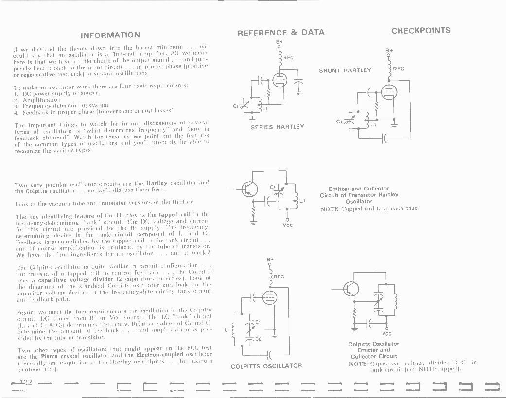
INFORMATION
If we distilled the theory down into the barest minimum . . . we
could say that an oscillator is a "hot -rod" amplifier. All we mean
here is that we take a little chunk of the output signal ... and pur-
posely feed it back to the input circuit ... in proper phase (positive or regenerative feedback) to sustain oscillations.
To make an oscillator work there are four basic requirements: 1. DC power supply or source. 2. Amplification 3. Frequency determining system 4. Feedback in proper phase (to overcome circuit losses)
The important things to watch for ín our discussions of several
types of oscillators is "what determines frequency" and "how is
feedback obtained". Watch for these as we point out the features
of the common types of oscillators and you'll probably be able to
recognize the various types.
Two very popular oscillator circuits are the Hartley oscillator and
the Colpitts oscillator ... so, we'll discuss them first.
Look at the vacuum -tube and transistor versions of the Hartley.
The key identifying feature of the. Hartley is the tapped coil in the
frequency -determining "tank" circuit. The DC voltage and current
for this circuit are provided by the B+ supply. The frequency -
determining device is the tank circuit composed of I., and C. Feedback is accomplished by the tapped coil in the tank circuit .. and of course amplification is produced by the tube or transistor. We have the four ingredients for an oscillator . . . and it works!
The Colpitts oscillator is quite similar in circuit configuration ... but instead of a tapped coil to control feedback . . . the Co!piIts uses a capacitive voltage divider (2 capacitors in series). Look at
the diagrams of the standard Colpitts oscillator and look for the
capacitor voltage divider in the frequency -determining tank circuit and feedback path.
Again, we meet the four requirements for oscillation in the Colpitis circuit. DC comes from B+ or Vcc source. The l.0 "tank" circuit (L, and C1 & n) determines frequency. Relative values of C, and C:
determine the amount of feedback . . . and amplification is pro-
vided by the tube or transistor.
Two other types of oscillators that might appear on the FCC test
are the Pierce crystal oscillator and the Electron -coupled oscillator (generally an adaptation of the Hartley or Colpills . . . but using a
pentode tube).
Lr
REFERENCE & DATA B+
SERIES HARTLEY
VCC
B+
COLPITTS OSCILLATOR
SHUNT HARTLEY
CHECKPOINTS
Emitter and Collector Circuit of Transistor Hartley
Oscillator NOTE: Tapped coil L, in each case.
Vcc
Colpitts Oscillator Emitter and
Collector Circuit NOTE: Capacitive voltage divider C, -C2 in
tank circuit (coil NOTE tapped).
'22

apoi.uad g (Indui Jo) pw8 ay>I pue aleld 5
anjll3ede3 aJ0113ede3 (Jol3npu!-padde) 'Jo) 1!03 paddel g
I1a1 aas Z J)a1 aaS ¡,
:Sa3MSNV
aqn' adrfi e sasn Jo'ell!3so paldnoa-uo.l3alg .ayi, 9 agnl ay) jo ay pue aqni ay' jo a l' uaaM'aq sdeadde IeiskJ3 ay) ley) s! Jolelipso lels,113 a3Ja!d ay' 10 aJn'ea1 Su!R1!Iuapi rfal a41,
Jap!n!p aSellon e se o' paJJalaJ aq lrl3!w yo!ynn
'sa!Jas u! onnl aqj Si Jo'elll3so s'I!dlo0 ayi jo anneal Su!n1!Iuapn nal ayd,
Si! 5! JOIeIIf3S0 rCallJeH aqi 10 aJnleal 8u!rf1!'uapi rCal ay,I,
Jall!1 ssed-nnol e se pasn aq pino3 leyl JaII!1 >I Iuelsuo3 adR' y e jo weJSelp e MeJQ
(papaa-J s! dei -Jai -ua3 e 'uo!'e3!1!I3aJ aneM-llnl Joj 'IaaJo1 I,uoQ) ilaM se walsrfs Jail!1-Ja!1!i3aJ ay) Su!paal JawJolsueJl ayl Moyc (Jols!saJ [mol) Jo's!SaJ ,Japaalq pue 'JaII!1 'nd -u! anil!3ede3 adrC1-!d yi!M Ja!1!IoaJ aneM -In e jo (11a1 ayl je) weJ8e!{3 e MeJd
:1NIOd)103H0 uo!>teJnó!;uo0 Jo;ellp3so AaI1JeH
2iO1V1110S0 031d1100-NOa10313
+9
3JV1-10A N331d3S+
s
Z
1131113 SS Vd MC1 111V1SN03 3d.1_ 1 o o
o -a r -O
1131311033 ./13
ao1slS=a a3033-9
1f1d10 \«:
3dnl Jo)ell!3so s!y' S1!'ap! sdlay lelsfrc 10 uo!Ie3og :gyON
801V1110S0 1V1SAa0 30!{3Id
indino. 01
1V1SAa3
+9
1ndN1 3V
EZl
Su!ssnus!p uaaq an .am sinoJi3 3iseq pue sivauodwo3 jo suo!le3!¡dde asay' Io awos padseJJ noif 1! aas cl aJay )u!odbl3ay3 ami( e Inoge mol{
sJolell!3so jo a do) ay' uo snoog poo8 jo Jagwnu e aJe aJayl uo!IewJolui aaow a1l p,norf 1! ''nq 'aJay slalluassa ay' non uan!8 an,aM (a)a 'sIooq -¡Nay u!) npn)s aJow op pinoys norf srol'II!3so 8u!pJeaaJ sl!e)ap Jaylanl Jo1 leyl puawwoaaJ am ncin)
Joic(l!3so aqi jo aield ayi Su!aq uaaJas ayi pue agn) 3po'uad ayi aie I!nJJ!3 sup jo sJa!ltluap! algeio¡v leu8!s
Joiell!3so ayi nld!11nw rf3uanbaJl sutil pue leuS!s Jolell!3so ay) jo ald!ilnw awos os paur I aq 1.1e3 1rnaJ!3 a'eld ayi 'osld Jo) ell!cso ayi Jo1 nl!l!ge)s n3uanbaJl pooS ap!noJd sdlay pue 'poo8 s!
siy,l, uo!)rJado Joiell!aso 3!sey ay) woJ1 pal3auuo3 peol ay) saielos! .11anr13a1Ja (I!n3J!3 aleld ayi) agni ayi j° I!n3J!3 Indl ro ayi ieyl sueaui s!y l a)eld Jolell!3so zyi se sanaas uaaJ3s ayi - apoluad ayl ja i!n3.r!3 alele] ayi uo puadap iou saop JadoJd )!n3.1!3 Jolell!3so ayi 'spdoro. Jaylo ul aqn) Joielll3so ay) jo aleld ayi anti palead' si agni ay) jo p!J8 uaaJ3s 3y) pue pasn si agnl apojuad e ley) I3e1 ayi ng alge!1!)ua3! s! Jo'ell!3so paldno3-uoJI3a13 ay,l
;asea su') u! 'p!.18 ayi) '!n3.:!3 Indu! ay) pue )!n3J!3 a'eld ayi uaaMian sJeadde lelsnJ3 ayi ley) si 1!n3J!3 a3Jai,1 ayi jo Ja!1!luap! rfan ayu, uo!)eaado Jo)ell!aso Jo1 slua!paJBu! papaau b .no aney am sny,1, s)uauodwo3 leudalxa ay) pue saauel -lJede3 aqni apoJ)aaladalu! jo uo!)eu!gwo3 e ny payslidwo33e si 13egpaal pue sa!1!ldwe agnl ayi '0Q ay' sa!lddns +g u!e8t/ Jo' -eIl!3so ley) Jo1 rfauanbaJl jo Jau!wJa'ap aw!Jd, ay) s! nlleJauaB ll weJáe.lp Jo)ell!3so ue u: uMOyS le)srfJa e aas noñ JanauayM
a3Jaid ay) jo weJBeip ay) ie non7

INFORMATION
THE SYSTEM APPROACH
We've spent a great deal of time so far teaching you about single components, such as: resistors, capacitors, inductors, tubes and transistors. We have brought some of these components together to
form basic stages or circuits, such as amplifiers, and oscillators. Now it's time we give you an overview of some systems that com- bine the components and stages into a total functional system. The two most important systems to radio communications, of course, are the transmitter and receiver.
As you already know, the transmitter has the job of producing a
radio wave, which is in turn radiated into space by an antenna system . . . and then it's the job of the receiving antenna to pick up this transmission and feed it to a receiver ... which processes the incoming signal and retrieves the "intelligence" contained in it
(code, music, speech or teletype).
Every system ... your phonograph, an automobile, a transmitter or a
receiver, etc. . . . has three basic elements . . . at least. These elements are: 1. An input 2. A processor 3. An output.
In the case of the phonograph . . . the input might be the grooves in the record ... the processor includes the pickup, the audio ampli- fier and the speaker system . . . the output is the sound waves, or disturbances of the air in front of the speaker/s.
The automobile takes fuel as its input .. . processes it through its engine and power train . . . and creates the output of motion of the wheels. Are you beginning to get the idea of what is meant by a "system"?
REFERENCE & DATA CHECKPOINTS
INPUT
INPUT- RECORD
OUTPUT PROCESSOR
A SYSTEM
PROCESSOR (PICKUP, AMP, SPEAKER)
SOUND WAVES) )
A PHONOGRAPH "SYSTEM"
FUEL IN ENGINE AND POWER TRAIN
MOTION OF WHEELS
AN AUTOMOBILE "SYSTEM"
CHECKPOINT: Every system has at least 3 impertant parts. These are: 1. The 2. The 3. And the
ANSWERS: 1. Input 2. Processor 3. Output
124

G I.
lJ3111WSNVa1 'WO
SNIVW L+3MOd WOad NI DV
J.-Iddf1S 213MOd
VNN3INV
dWV VNId a3d3f18 'DSO
)ndino ou (dn) uado i! gilM euuaiue aqi oi indino 32J SulanpoJd s!
Jai!wsueJl aqi 'pasop rfan aqi g!M dn I! sa( pue uMop rfan Su!puas aqi spioq joieJado aqi Suol nnoy uo Su!puadap sqep pue s1!p
Jo wjoJ aqi u! s! aouaSyla)u! aqi 'Ja)!wsueJ MD aqi jo asea alp ul
¿i! I,us! aidw!s waisÁs euuaue aqi oi indino se paj s! ÁrieulJ pue saSeis (eu!J pue jaJJng aqi ñq pa!J!ldwe pue passaooJd si golyM leuS!s /fauanbaJJ o!peJ e ow! s!q sassaaoJd Jo)eillaso aqi Do oiu! Álddns JaMod aqi rfq passaooJd si ÁSJaua leo!Jioala s!ql rflddns JaMod aqi Su!paaJ sau!l JaMod Dv aqi jo ndu! ue seq Ja!wsueai s!gi uagi RjewwnS ur
paJ!sap J! saSeis Su!paaaaJd ay' jo auo u! paica aq p(noa i! inq aSeis reu!3 agi u! (apoo puas 01 JJo pue uo pauJni) paifan aq Ár(eJauaS ((!M pup s!yi Jo JaI!wsueJl e ey ppe iyS!w aM
waisrfs euuaue alp ñg aali!wsuej ag o argelins lanai e o reuS!s 32J aqi salJ!(dwe jay;jnJ eyi ('y d) Ja!J!idwe JaMod leulJ al -11 s! y d leu!3 agl ti
Jolel(!oso agi wojJ (JalJ -Owe reu!J aqi asen s!gl u!) peor aqi alelos! oi pue lanai (euS!s aqi dn piing of aSes jalJlldue 321 ue isnl si a8eis JaJJnB aqi,
ÁauanbaJJ owed paparas awos ie (euS!s indino ue ow! i! 01 paj saSei(on aqi sljanuoo il reuS!s 32J aqi sap!noJd Joieli!asp aqi,
Jali!wsueJi agi u! saSeis jagio aqi Áq papaau sluajJn3 pue saSei(on aqi tie sap!noJd Á(ddns JaMod agl ¡
:SMOiIOJ se d(le!luassa s! weJSe!p 13orq s!qi u! >loorg gaea jo uo!I3unJ aql
suo!ss!wsueJl JoJ rfayi apoo e Á parSan aq prnoo leqi Jai!wsueJ aSeis-E aidw!s e Jo weJSe!p >13o(g aqi ie >looq
E
7.
¡IJeis pooS e oS an no!S aas noÁ os swaisrfs a!uoJ13a(a (ie 10110,141 pasn ale sluawala pue g'H Suisn siin3Jl3 Su!un pue Sulldnooap '8u!(dno3 sno!Je¡f paiejado rfJaieq ssalun 'ivawd!nba 3!uoJiaa(a ire Á((enlJ!n u! punoj aje (sJal(!J pue sJa!J!ioaJ) sa!(ddns JaMod sJantaaaJ pue sJalilwsuej yoq u! pasn aje sjoeii!osp pasn gonw aje (32í) R3uanb -ajJ o!peJ pue (3y) Á3uanbaJJ o!pne gioq sJa!J!rdwd SuluJeai uaaq aney noÁ saiseg alp jo uo!eu!qwo3 awos aq ii!M yl!M >ljoM am swaisÁs aqi ire imp ySnoy Áes o uaiseq s iag JaaJe3 jnorf u! iu!od slip le ÁJoayi )!n3J!3 pueisJapun ¡(!M noÁ )eyI paoadxa lou s,i asagi jo q3eoJdde swasRs aqi IaS o noÁ iueM frdw!s am Jail!wsueJl (l3ss) puegap!s-a(Su!s e se uMoun 'Jall!wsueji INy Jo wJoJ le!oads e pue Jall!wsuej adÁ W3 ue 'Jali!wsuejl adÁi IWy ue 'Jal!wsuej (apoa Jo) imp y :aje le Tool ILaM sadÁi ayl waisifs Ja))!wsueJi aqi jo MalnJano n3!nb e anei Mou s iag
IN31SJlS lJ311IWSNVIjl 3H1

INFORMATION
Now, to add audio intelligence directly, via microphone, tape deck or whatever ... a couple more blocks are added to our basic trans- mitter block diagram.
Note in the diagram that we have added a speech amplifier and a
modulator block. The speech amplifier obviously amplifies or builds up the level of the audio signal. The modulator stage builds the audio signal up further, to a level that can he fed to the modulated RF stage. The modulated RF stage, in addition to building up the RF signal level, as in the CW transmitter . . . also, combines the audio information with the RF to produce a modulated RF output signal . . . which is fed to the antenna system to be transmitted. The inputs to this system are: the power line AC plus the audio speech, music, or whatever. The transmitter processes this and generates an output of modulated RF wave or signal.
There are several systems of generating an F.M. (frequency modu- lated signal). The most direct method: the transmitter's oscillator is directly caused to change frequency by the audio signal. This method is called the "Direct" method of F.M. A simplified diagram is shown in column 2.
A quick "tour" through the transmitter yields the following: The oscillator generates an RF signal. The frequency multiplier stage amplifies and multiplies the frequency of the oscillator sig- nal. The final RF power amplifier (P.A.) builds up the signal to an appropriate level for transmission by the antenna. The modulator takes the audio signal as input and processes it so that the output of the modulator changes the frequency of the oscillator in accord- ance with the audio intelligence . . . thus directly an F.M. signal. The power supply does its usual job of providing appropriate DC
voltages and currents for all the stages ... having processed the AC
input from the power mains.
Now, our special type of A.M. transmitter . . . the SSB (single- sideband) transmitter. Look at its functional diagram.
Incidentally, this is known as the filter -type sideband transmitter. There is another way of creating a single sideband signal . . . the phasing method . . . but we won't discuss it here. as the more popular method by far is the filter method.
"Walking our thoughts" through this transmitter, we see that there are several new blocks not shown in our other A.M. transmitter. DON'T GET WORRIED . . . YOU DON'T HAVE TO MEMORIZE THIS! Just get the concepts in mind ... and you've done well.
REFERENCE & DATA CHECKPOINTS
OSC --*BUFFER --« RF AMP
vANTENNA
f
I
MICROPHONE
POWER SUPPLY
SPEECH AMP MODULATOR
A.M. (amplitude modulated) TRANSMITTER
OSC. -- -
MO
FRED. MULT.
RF P. A
I
POWER SUPPLY
1
ANTENNA
AC POWER IN
DULATOR AF INPUT
SIMPLIFIED FM TRANSMITTER
OSC BUFFER
OUTPUT BALANCED BAND BAND LINEAR
MODULATOR PASS FILTER
MIXER PASS FILTER RF AMP
1
AF
I ) SPEECH
MICROPHONE AMP
SIMPLIFIED SSB TRANSMITTER
OSC.
126

lndinp E 30SS0301d z
sleuS!s L3uanba,IJ olpnd aqi pue u! raMod Dy aqu, 'L
:Sa3MSNt/
waisis rall!wsueri aqi jo aqi parap!suo3 aq iyS!w wai
-sis euualue agi 01 rawIdwe AH Ieuq ayi wor3 paj sleuS!s 3g paiElnpow agu
a4.L ¿waisis 3!seq
e jo ired ieyM se paz!rewwns aq 1ySlw sralilwsueri aqi jo saSeis sno!ren ayu,
aweN sindu! jo sadLi 3!seq He srail!wsuerl ass pue W
agi raMsue panIel aneq
ay 1 g aqy
'E
waq i OM! aneq
94.1. l :SuIMOIIoj
'swaisLs se ti!Ienb inoqe aM srail!wsuerl aqi He a3uls
:1NIOd>133H3
LZl
¡iu!odrag3 aqi Rru, L3uanbar! Ay Su!lelnpow aqi 01 lenba lunowe ue Rg t3uanb -arj ra!rre3, ay1 Molaq pue anoge readde sleuS!s puegapls asaqi aas ue3 nL sy zHW S00'L le leuS!s puegap!s raddn, ay' pue
AON3n03a3 'zHW 566'0 le ra,Hol aqi 'aseo s!yi uI palerauaS aq o1 1HWI
0
13A31 L13MOd
puegap!s sal3uanbar, Mau awos asnea Lileni3e aM IeuS!s AHue aielnpow -apni!ldwe aM uaqM )eqi suaddeq os i! L3uanbar} ra!rre3 aqi Molaq zH OOOS pue 'L3uanbar oal.iaPo ayi anoge zy 000S luasard LSraua awos ()sip inq zHW lo Rauanba ralrre3 ayi le LSraua R3uanb
/1 =Hw 500.1 =HIN
966'0
xvw -an owe.' R¡uo lou s! aragi leyi Mogs aM 'golans ise¡ .ino u! a3!1oN
38 031V'000w 3o
NOI1V1N3S3lJd311 1V3IHdVa9
a
31Vd olOnV lV 3anllldWV NI ONIAaVA
d3IddV3 3a
a0IN
3N01 olonV 03131n1d1K V
V
o1OnV 031311dWV
AVM 3d lVNI3
L1lU
dWV olanV
3d a31311d1NV
833408
38 3O N0I1V1N3S38d38
lV3IHdaaO
3N01 OIOnV 'H 0009
---Q 01W
o 03I3 38
'OSO
auoi aneM-au!s zlral-i 0005 e ql!M zHW L jo ra!rreo e g1!M rail!wsuerl Wy ue aielnpow aM uagM suaddeq ieyM aiou pue a3uanbas aie!rdordde aqi u! z uwnlo3 u! say3lals aqi ie now] aneM palilwsuerl aqi u! ivasard t3uanbarj auo ueqi auow Llleni3e s! aragi palelnpow-apnilldwe Su!aq s! aneM AH ag1 uayM legl puu pinoM aM ra11!wsueri Ivy ue Lq paiilwsueri Su!aq s! raMod agi aragM 1e naad e anel 01 araM aM !i
wayi inoqe ivawow e isnl ro.; >lle1 s,lal s/puegap!s wral agi pauolluaw aneq aM a3uls
indino si! le lanai pa.l!sap aqi 01 ieuS!s ass iueilnsar aqi dn spl!ng rawldwe
aqi asrno3 jo 'pue IeuS!s ay1 srall!j raylrnj roiell!oso-rax!w aqi Su!Molloi rail!{ ssedpueq agu indino jo R3uanbarj par!sap aqi le an!rre oi rapro u! sroielll3s0 pa)eu!proo3 r!ayi gl!M srax!w jo saSeis leranas aneq Lew ralilwsueri gss ue ioei ul wnrl3ads o!pe.l aqi u! i! iueM aM aragM o1 leuS!s ass aqi jo L3uanbarj alp anow oi pasn are i! Sulpaaj rolelll3so ixau pue rax!w aqu, Indino si! ie leuS!s ra!rre3 pa3npar 'puegapls-alSu!s e aneq Mou aM 1no parail! s! spuegapls agi jo auo aragM rail!] ssed-pueg aqi 01 pa.; uaqi Si IeuS!s pueqapls-palqnop, raIr1e3 pa3npar s!qy leuS!s L3uanbarj ra!r1e3 pa3npar LliearS e pue a3uaSl(lalu! aqi u!eluo3 g3!q.nn sleuS!s pueqapls rannol pue raddn agl Llle!luassa s! a8eis s!qi jo indino aqi iegi Les Lldw!s trig arag ¿LgM jo Lroagl daap ay] o)UI iaS I,uOM ant IeuS!s L3uanbarj ratrrP3 agi lno a3ue -leg ol s! gol si! roielnpow pa3ueleg aqi Nloolg Mau e oi awo3 aM MON i! Lj!ldwe uayi 'leuS!s AH ue aierauaS saSeis asaqi 'aro!aq sy aSeis raiinq pue rOielll3s0 ue seq osle rail!wsueri s!qu .(lanai leuSls olpne aqi dn pl!nq o1 asod.md awes aqi roi) ra1ltwsueri Wy aldw!s rno an!! isnl rau!ldwe goaads e seq rali!wsueri s!yu,

INFORMATION REFERENCE & DATA
How did you do on that? Do you know how to find the upper and lower sideband frequencies now? I hope so! Since we are on the subject of the modulated wave and transmitters . . . here's some- thing that might be on the test you're preparing for. For an A.M. signal (single -frequency modulated), what are the relative powers of the carrier, sidebands, etc?
Look at the illustrations in column 2 . . . then come back to this column and we'll discuss the important facts.
Without modulation, the power out of the transmitter is the carrier power ... whatever that might be. When we 100% modulate the RF with a sine -wave, single -frequency audio signal . . . the amplitude of the RF wave changes at the audio rate. As we said before ... we create sidebands. Note from the sketch that the peak amplitude of the modulated wave is 2 times the amplitude of the unmodulated carrier. Assuming that the RF is fed to a constant impedance load (50 ohms for example) ... if we double the E across the load, the current through it must double. Since E is double and I is double, and power equals E x I . .. then we have 2E x 21 ... thus 4 times the power . . . at the "instant" of peak amplitude of the modulated wave. This business of calculating power at a given instant of time gives us an instantaneous power answer. If you were to find the average power in a 100% sine -wave modulated RF wave you would find that there is the carrier power + the power in the side - bands coming from the audio signal . . . the result is 1.5 times the power of the unmodulated carrier. So, briefly listing the important numbers for you to remember ... 1. Average power of unmodulated RF = carrier power 2. Average power of 100% modulated RF = 1.5 times carrier power. 3. Instantaneous peak power for 100% modulation = 4 times carrier
power.
By the way ... it is possible to see this "graphical" representation of an A.M. signal by looking at the output of an A.M. transmitter using an oscilloscope. The oscilloscope is an instrument that you will probably want to put high on your list of test equipment you should obtain.
"ENVELOPE"
Eo
t UNMODULATED RF (CARRIER)
MODULATED RF
AVERAGE POWER HERE= POWER OF CARRIER
PEAK OF ENVELOPE INSTANTANEOUS PEAK ENVELOPE POWER
BECAUSE EP .2 x Eo AND IPK 2 x 10 P=E x I, THUS PEAK POWER= 4 x CARRIER POWER
AVERAGE POWER OVER COMPLETE °CYCLE'' 1.5 x CARRIER POWER DUE TO ADDITION OF SIDEBANDS
CHECKPOINTS
CHECKPOINT: 1. If a transmitter's carrier frequency is 3.5
MHz, at what frequencies do the upper and lower sidebands appear if the modu- lated RF stage is being modulated by a 10 kHz. sine -wave audio signal?
USB freq. = MHz. LSB freq. = MHz.
ANSWER: USB freq. = 3.51 MHz. LSB freq. = 3.49 MHz.
128
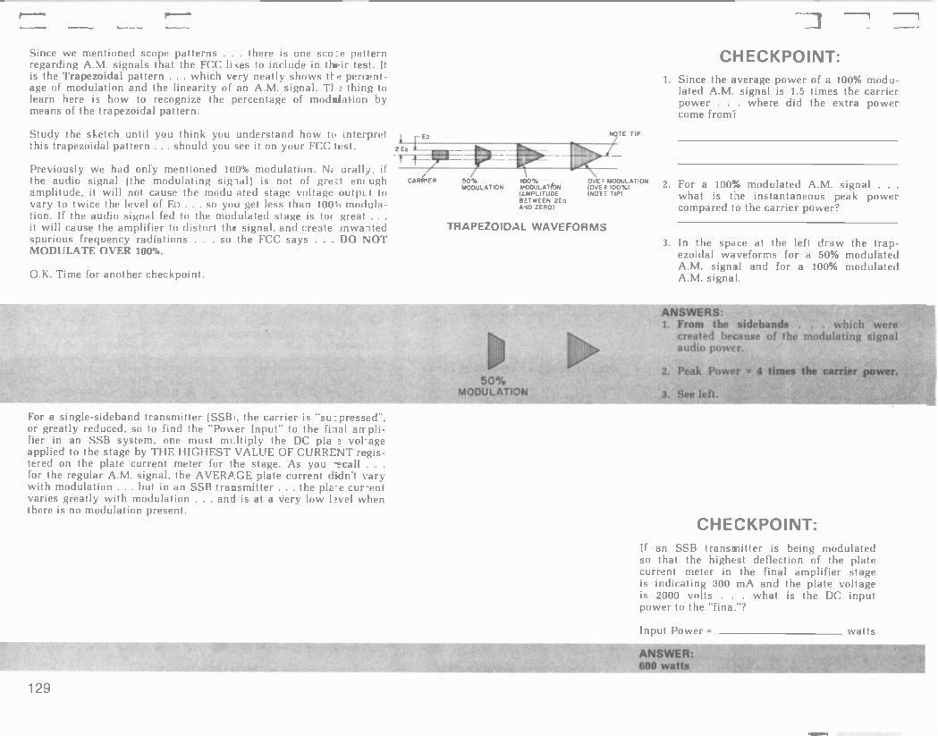
SIIeM
s;leM 009 1:13MSNV
= raMod Indul
¿eulj ayi 01 raMod Indu! OQ ayi st leyM sllon 000Z s! a8ellon aleld ay) pue t/w 00E Su!Ie3!pu! s[ a8e)s ragIdwe Ieug ay) u! ralaw luarrn3 aleld ayi jo uo!l3a)jap IsayS!y ay) imp os palelnpow Swag s! rall!msuerl eSS Ue II
:1NIOd)103H3
I,lal aas 'E
raMod, rai.ue3 ayI sawn 6 _ raMod Mead Z
raMod o!pne jeu8!s 8upejnpow ayl ,Io asne3ag palear3 BraM yatyM spuegapjs mil won I
:S!l3MSNV
IeuS!sWd pale)npow %OOi e ro,l pue Ieu8!5 Wd pa)ejnpow %OS e roj swroJaneM jep!oza -derl ayi Merp gal ay) Ie aaeds ayi uI E
¿raMod ra!rre3 ay) oI paredwo3 raMod yead snoaueluelsu! ay s! )eyM
IeuB!s IrsId pale)npow ÁOOI e rod Z
;wor1 awo3 raMod er)xa ay) p!p arayM raMod ratrre3 aq) saw!) g L s! )euS!s inn/ pale) -npow %00L e jo raMod a8erane ay) a3u!S i
:1NIOdM03H3
Ii0IlV1)100W %05
SWliOd3AtfM lt'QIOZ3dV)dl
(dll lON) (x001 l3nO)
N011Vln0oW :3A0
(oa3Z anV 032 N33M1:6
3anllldW7) Ng1VlnaoN N011Vlnaow
% 001 %os a31áaVo
6Zl
luasard uollelnpow ou s! arayi uayM land Mol fran e le st pue uollelnpow yIlM Allear8 salren lua,:rn3 aie)d ay) rall!wsaerl SSS ue u! my uo!Ielnpow y)!M rfren l,up!p luarrn3 oleic! 3Oá2I3At! alp jeu8ls W V re)n8ar alp ro,}
IIe3v norf sy aSels ay) roj ralaw Iuarrna aleld ay) uo paral s!8ar ,LN32I21f10 AO 3I1yVA .LS3H9IH a8e)s ay) o) palldde
a8e_Ion a:eld 0a ayi rfld!)Iiw Isnw auo 'walsrfs flSS ue u! rag -!Id.ne Ieu!1 ay) 01 Indul ratiod alp pug oI os pa3npar rfllear8 ro 'passard_ns s! ra!rre3 ay) 'i ENS) ra)Ilwsuerl puegap!s-a18u!s e rod
lurodyaaya ra(4loue ro} aw!l 'y0
'%00T 213A0 3.L\/7f111OW ION Oa ' ' srfes 00d ay os suo!le!per rf3uanbarl sno!rnds palcennur a)ear3 pue leuSls ay) Irolslp o) rag!Idwe ay) asnea )I!M 1!
)ear8 301 s! aSeis palelnpow ay) o) paj leuS!s o!pne ay) p uoll -ejnpow 11-00L ueyl ssal Ia8 norf os 03 jo lanai ay) a3!MI 01 Áren oI -id)no aSe))on a8els pa)e-npow ay) asne3 Iou IItM 1! 'apnl!Idwe y8n3ua I1ar8 jo Iou s! [IeuS!s Su!Ielnpow ay)) jeu8!s o!pne ay) j! f)Iern 3N uo!lelnpow goODi pauo!Iuaw rf)uo pey aM rtlsnolnard
a3z Isal 33.4 rnorf uo I! aas norf p)noys uralled Iep!ozaderI s!y) c3J f Iardralu! .n Moy puelsrapun naif yu!y) Wort Illun plays ay) rCpn)S
uralled lep!ozaderl ay) jo sueatu rfq uo!Ie¡npow jo a8elua3rad ay) azlu8o3a1 01 Moy s! aray weal ol Su!yl 11. IeuS!s w t/ ue jo rfI!reau!I ay) pue uo!lelnpow jo a8e -Iuaorad 041 smogs rflleau Áran 11314M uralled lep!ozadery ay) s! )1 Isal r!ayl u! apnl3u! oI say!' 00d ay) Ieyl sleuS!s KV Su!pre8ar wailed a=o3s auo s( arayl suralled ado3s pauo!Iuaw aM aau!S

INFORMATION Another area of information we want to mention before leaving the broad subject of transmitters . . . and that is the topic of neutralization of RF amplifiers.
If you will think back a little, you will remember that we said an oscillator was simply a "hot rod amplifier". As you can recall .. .
it really boils down to the fact that any amplifier that has some feedback "in proper phase" can become an oscillator.
It's undesirable for an amplifier to function as an oscillator when the circuit is to be used as an amplifier. In a transmitter ... if an amplifier goes "into oscillation" ... it will generate spurious radia- tions that can interfere on the radio bands . . . not to mention it causes loss of efficiency and other unwanted side effects.
The method that is used to minimize the effects of unwanted feedback in an RF amplifier is called neutralization.
Generally, this unwanted feedback from output circuit back into input circuit is due to the "interelectrode capacitance" between plate and grid of a tube.
To neutralize the EFFECTS of this Cgp . . . there are several methods of "balancing out" this undesired feedback. The main thought here is that a signal path must be provided which will ALSO feedback a signal from output to input ... but will cancel the effects of the undesired feedback signal. The most common way of achieving this is with a NEUTRALIZING CAPACITOR. The two basic methods . . . from which other methods are derived, are shown.
Plate (sometimes called Hazeltine) neutralization is characterized by the Cn being connected from the "bottom" of the plate tank (LC) circuit and the grid. Grid (sometimes called Rice) neutraliza- tion is identified by the C being connected directly at the plate ... and going to the bottom of -thegrid inductor.
You are not required to be able to "draw these circuits from scratch". You should be able to recognize them ... or be able to draw in the neutralizing capacitor between the two correct points if you are provided a drawing with everything but Cn.
REFERENCE & DATA
PLATE (Hazeltine) NEUTRALIZATION (CN = from bottom of plate tank directly to grid)
GRIDE (Rice) NEUTRALIZATION (CN = directly from plate to bottom of grid circuit inductor)
CHECKPOINTS
CHECKPOINT: 1. For plate neutralization of an RF ampli-
fier, the neutralizing capacitor is con- nected between
2. For grid neutralization of an RF amplifier, the neutralizing capacitor is connected between the
ANSWERS: 1. Between "bottom" of the plate tank and
the grid of the tube.
2. Between the plate of the tube and the bottom of the grid inductor.
130

'%SL = 001 X SL' = Á3uala[JJ3 001 X 006/00E = aaoJaaayi R3ual3lJJa
M OOfi = JaMod indino DV M006 ='dw 006 X "0001 = JaMod indut pQ
:lJ3MSNV
LM 00E se paJnseaw sr JaMod indino AH alp pue dw 006 sr ivaJJn3 afield sil '"0001 sl Mellon afield Si! Jl a8els AH reu[J Jaipwsue.l e jo if3uala!JJa afield all si fegm
:1NIOdM03H0
il3N3I3I333 31t11d 1:103 v1111A180A 3E11
aSeis of fndui JaMod = NI d peor oi JaMod DV JO d21 = -WO d
% U! if3ualalJJa = JJ3 :aJagM
lCl
zHpl SSbJ pug 0001 lo salauanb -adJ IeulSlJo oMi ato oi uotilppe ul aq pinoM asagy (zyn SS17) zyn 0001 - S461 pue (Min SSbZ) zH1 0001 + SS61 aq pinoM salauanbaJJ Mau alto IeuSls zypI SS61 e pue IeuSls zip( 0001 e paxlw am jr 'ardwexa JoA sal3uanbadJ' o,Mi aqi jo aauadalJip pue wns ayI aq IIiM salauanbaJJ Mau asaq,L salauanbaJJ Mau aanpodd oi dagfaS -of sieuSls oMi xiw of sueaw auÁpoaaiay waal agi satuoJfaala ui
adrfi sito inoge mom) os paau noif siaeJ rfan ayI Suissn3sip auto Jno puads rLaM Sulnia3aJ jo waisrfs auifpoaiayaadns aqi asn sJania3ad isow asne3ag
snJOM wafsiSs suoile3lunwwo3 agi jo Jleg puo3as slgi Mol aas s ia`I JanlaaaJ ato S!
Jley dayfo aqi sainuiw Mal ised ayl JoJ Suissn3sip uaaq aneg am y3igM JafilwsueJl agi sr waisrfs suollealunwwo3 e jo Jleg auo
1:13n1333E1 3H1
Iua3Jad OL aq won't
(4) d /f3uatalJJa ayl (M 001 = ivaJJn3 afeld sawli aSeilon aleld lo Ianpodd aqi 'sl ieyi) sileM 001 aJaM aSeis ayi oi indui JaMod Q
001. X = JJ3 agI pue Jaiaw d21 ue ¡lc) padnseaw se '(aldwexa JoJ 'euuaiue ue (33) Jno d jo amid ul peor ani slsad e)peor fwwn e o JaMod jo sileM I P I i,.P I P i .32I
0L padarttrap JalllwsueJi e ul JalJildwe d21 IeuiJ alp ji :aldwex3
SuiJidsueJi sr r13ualatJJa jo aSeiva3Jad IeIM auiwJalap uaqi (penl Jagio Jo euuaiue) peor ato oi paJanlrap Sulag sr daMod
d2I qanw Moq sueaw awos ñg auiwJaiap (ivaJJn3 aleld sawil aSellon aleld) aSeis ato of indui daMod alp aieln3le3 si padinb -ad s,legi ile aSelua3Jad ui rf3ualaiJJa ayi pull 01 'sJaiJildwe 32J JoJ 'og Indlno s,aSeis agI se peor ato 01 padanilap si daMod qanw Moy 01 paJedwoa aSeis aqi of ui Ind si JaMod qanw Mog oi sJaJad ÁlledauaS i 'pauolivaw si aSeIs e JO K3ual3iJJa danauagM
auo sigi uo ul norf anla s,iar os 'aiel -nare3 oi aldwis ailnb Head sr Ii sdaiJiidwe da iºulJ Jo if3ualoiJJ3 aierd aqi SuipJeSaJ ¡sal Jlall uo uoiisanb e nse of swirl DDd
sJanla3aJ of uo anow ant adolaq SuluJeal Jo ilq !cur.) auo

INFORMATION The superheterodyne receiver takes the incoming signal ... mixes it with a signal developed by an oscillator stage in the receiver .. .
and produces new frequencies . . . from which ONE band of fre- quencies is selected by tuned circuits to be passed along to the rest of the receiver circuits for further "processing".
This "new" frequency (really band of frequencies in which there is the "carrier" and the "sidebands" in which the intelligence is contained) is generally chosen to be much lower in frequency than the transmitted signal . . . but much higher than the audio range ... or "super" audible . .. hence the term "superheterodyne" receiver. The reason for Mixing and producing this new frequency (called the Intermediate Frequency) is it is much easier to build stable, high -gain amplifiers at lower frequencies. Also, if we design our receiver oscillator so that we tune (change) its frequency at the same time we are tuning to different stations ... we can make it so that the Difference Frequency between the local oscillator signal and the incoming RF signal is always the same. This means our intermediate frequency (I.F.) amplifier stage(s) can be "fixed tuned" . . . and we don't have to "track" several stages' tuning mechanisms to make the receiver work. Do the Checkpoint.
ANTENNA
All right! turn on your "biological computer" (your brain) and let's take a mental walk through a typical superheterodyne receiver and follow the signal as it travels from the receiver antenna . . .
through the various stages of "processing" . . . on out to the speaker and of course, you know what happens from there on.
Let's think our way through the "block diagram" of a receiver at the right. We'll try to mention the key job (or processing) each block performs in this functional "system" ... the receiver.
First, the RF amplifier does just what its name implies ... it builds up the RF signal coming from the antenna.
132
REFERENCE & DATA CHECKPOINTS
RF AMP
"CONVERTER" r 1
MIXER
LOCAL OSC.
I.F. AMP.
2ND DETECTOR
f
B.F.o.
BLOCK DIAGRAM OF SUPERHETERODYNE RECEIVER
WEAK MODULATED RF SIGNAL
AMPLIFIED FF SIGNAL
RF AMPLIFIER -BUILDS UP WERK SIGNALS
1.
CHECKPOINT: The term heterodyne means
a. To mix two signals together to produce new signals.
b. To separate two signals in order to isolate them.
c. Neither of the above.
2. The new frequency (or band of frequen- cies) produced by mixing action in a superheterodyne receiver is called the
frequency.
3. This new frequency is usually (lower? higher?) than the "incoming" RF from the radio station ... but is higher than the
range.
ANSWERS: 1. A 2. Intermediate frequency 3. Lower than RF incoming
. higher than audio
AUDIO AMP

OS
1VN9IS '0'3'8 ® I
1VN9 S' 1 1 H 130 010nVInoJJJ
Ino 1aN91S (IOnV
1VN9IS 3'r 031311dWV
80133130 ONZ
1VN9IS dl
1VN9IS hc 031V 100i1
S39V1S 80 39 VIS 03Nn1-03XIJ
!!31!l3NNO3 ao a3xIW
Woad 1VN9IS
3'r
dWV dr
£El- (jol3a)ap )3npoJd e paiie3) Jo)3aiap adÁ) gSS
le!aads e 4)IM uo!)auniuoa u! pasn s! pue (pa)i!wsueJi Su)aq s! g3 ou asne3ag dn s! /fan ay) uayM a3ua115 pue g3 SIIWSueJI pue /fan s!y sasop aapuas ay) aw!l ÁJana punos RJ!e ue Sulaeay füdwls noÁ ueyi aayiea) auo) o!pne ue aanpoJd ol uo!Ida3aJ Mp JoJ pasn s! aSeis Ogg ay) ley) aagwawaa rfidw!s 'Mou Jog sJan!a3 -aJ ggg u! pasn l!n3Jl3 joi3alap jo adrf) Iel3ads e JoJ pasn osle si Ogg y laSUeJ olpne ay) u! s! Á3uanbaaJ a3uaaaJJ!p J!ayI pue Jay)aSo) ,)eaq aje sieuS!s oMi ay) uayM) auo) aiglpne ue aanpoJd o) IeuS!s g 1 ay) g)!M pax!w s! IeuS!s Ogg at)) 'apo3 Su!nta3aJ uayM aidwexa Jog ifjessa3au rfia)niosge s! aSeis sup '(ggg) sieuS!s -pueqap!s-a!Suls Su!n!a3aJ JoJ Jo sieuS!s apo3 Su!n!aaaJ Jog aoi -eli!3so-Á3uanbaaJ-leaq sueaw sl41 Ogg palagei n3oig a41 aa!IoN
awoy ie o!pea a(gel iniy JeinSaJ JnoiS u! jeadde l,usaop ley) sJan!a3aJ suo!)e3lunwwoa Áuew u! sJeadde ley) n3oiq auo s! asay) walsÁs ay) u! )ulod sup )y
(olpne /quo 81.1!A P91 'IeuS!s AN ay) sanowaJ) uo!IewJoJu! o!pne ay) Jano3aJ 01 leuS!s ay) saleinpowap Jo)3a)ap ay) 'Jan!a3aJ ay) u! 'xO IeuS!s ayl uo a3uaSliialu! o!pne a41 Ind o) JapJo u! g3 ay) paleinpow am Jall!wsueal ay) le 'Jagwawa3 I! saleinpowap pue leuSls gi paleinpow ay) sassa3oad ,Jo)3a)ap pug sum, Jo)aa)ap 1514 ay) paiiea saw!lawos s! pue IeuS!s ay) Jo aJn)eu ay! Su!Sueya osie s! aSe)s Ja)Januo3 ay) asneaag (JantaaaJ )ayaadns ayI u!) 101331ap puo3as ay) mica saw!)awos s! aSe)s s!y1 IeuS!s g1 paleinpow ay) woJJ uollewJoJu! (!pne ay) poop 0) s! I! gol asoyM 210.L3313Q e o) paj uay) s! IeuS!s Ji palJlidwe slyl
Indino sit w IeuSts JaSuoa)s ganw e 0) lndw s)! Ie IeuS!s >teaM RIJ!eJ a41 dn pi!nq 0) s! uo!)aas Ja!J!idwe g) ay) jo go( ay j, (s)a8els aa!J!idwe gl ay) 01 Suoie )t ssed pue JalJanuo3 Jo Jax!w ato jo indino ay) le )uasaad sieuS!s sno!Jen a41 Ile woJJ IeuS!s gi s!y) Daps Mou (sjawaoJsueJ) gl paile3) s)!n3J3 paunl
(aSels Ja)JanUo3 Jo) Jax!w pue Joleii!3so ayI Áq RauanbaaJ g i ue 01 palJanuo3 uay) aSe)s aa!J!Idwe 33 ay) Áq palJlidwe uaaq sey uotlels owe.) ay) woJJ leuS!s Su!woau! ay) JeJ os
rfauanbaJJ Mau e oI ¡euS!s Su!wo3u! 341 S.I.213ANO9 I! asneaaq s! s!41 a8e)s 2I3 L213AN0 041 palie3 s! I! aseo sup ul uo!I3unJ Sutx!w pue ao)e¡i!aso ay) wJoJ -Jad i!!M aSe)s auo saw!) Áueyl (sieuS)s gi ayI /fiuo ssed r Suoie si!naJ!a paunl ay) 'JanaMoy JallJea pauo!luaw am 513410 ay)
3S0 staid) Á3uanbaJJ gi ay) s! Jaxiw ay) jo indino ay) pue Jax!w ay) 1VN9IS '3S0 1,1901
-® ',V3°,
uI pax!w aje sieuS!s oM) 35941 Ja!J!idwe AH alp woJJ paJ g21 ay) pue leuS!s Joleii!3so ay) :slndu! oMI Su!l)aS si JaX,w ay) 'aas noÁ sy 1VN9IS
a)e!paw AON3n03Md dl=Indino 113XIW
I
J a31M3nNO3
dWV3M woad
3a
(g'l) if3uanbaJJ -Jalu! ay) ilea am ñauanbaJJ Mau ay) aanpoad 01 Japao u! uo!l.els o!peJ ay) woJJ IeuS!s 8u!wo3u! a4i 4l!M paxlw aq 0) s! y3!4M ieuS!s ay) sdoianap Joleii!3so ay) )no pajnS!J ÁpeaJie rfigegoJd aney noÁ sy uo!I3unJ Jax!w a41 pue ao)eil!3so 15301 aq) se J9n93 aJ )ayJadns ay) u! 01 pajaaJaa saw!lawos uo!l3unJ ao)e11!3so
ay) :suo93onJ oM) aJe n3olg 5!41 u! imp aa!lou iI!M noA JalJanuo9 ay) aJoJag pauo!)uaw ),uaney am aweu e sasn volg )xau s!4,1,

INFORMATION
Out of the 2nd detector circuit comes our long-awaited audio signal. This signal is then amplified by the audio amplifier stage(s) and built up to drive the speaker.
There ... that trip through the receiver wasn't so bad after all, was it? Try the checkpoint to see if you picked up the most important facts.
How did you make out? Learning the block diagram of ANY system will help you understand it. It sort of gives you "pegs to hang your thoughts on". Makes it easier for you to "think" your way through a system. It gives you what someone has jokingly called the "GO- ZINTA-GOZOUTA" theory. Meaning: it helps you to learn what signal or input "goes into" a stage, or functional block . . . and what signal "goes out of" that stage or block. Once you have learned a system's block diagram and what type signal should go into each block and come out of each block ... you've gone a long way toward understanding how the system works. It also helps in practical troubleshooting of electronic systems. For example, if you know that all the appropriate signals are arriving at the input/s of a stage ... but the output is missing or abnormal ... you are pretty sure that the trouble is in that stage ...
REFERENCE & DATA
2ND DET.
nnAF
AF AMP
AF
2.
3.
4.
5.
CHECKPOINTS
CHECKPOINT: 1. What stage in a receiver demodulates the
modulated I.F. signal?
What stage(s) in a receiver changes the incoming signal(s) to a new frequency range?
Which stage or stages in a receiver build up the I.F. signals to a higher level?
Which stage in a communications receiver is needed in order to produce an audio tone for C.W. reception?
Which stage in a receiver builds up the incoming RF signal to a larger amplitude signal?
6. What is the job of the audio amplifier?
7. What stage(s) in a superheterodyne re- ceiver is sometimes referred to as "fixed - tuned" stages?
ANSWERS: 1. 2nd Detector (or detector) 2. Converter (or mixer & local oscillator) 3. I.F. amplifier 4. B.F.O. (beat -frequency -oscillator) 5. R.F. amplifier 6. Builds up audio to level needed to drive
speaker. 7. I.F. amplifier stage(s)
134

S£l
N3A1303LI
VNN3INV IIWOOdVW
H1JN37 3Ab'M t7/1
alod!p agl PaIIe3 sawqawoS VNN3INV Z1I33H
3NIl NOISSIWSNVal
3OVdS
k-H19N3-1 3AVM+1 Z/l
213111WSNVa1
VNN3L1 V \\\l\\ll VNN3INV
euualue ,!uo3Jeys1 aqi palle3 uno) aneM-Jalxenb aqi pue 'euual -ue (z)Jay alp palle3 ualJo) aneM-Jleg aqi :aJe sadÁl oM1 asa41,
sadÁl Jaw rfuew ol leluaw -epunJ aJe ya!yM seuualue jo sadÁl a!seg OMI lsnl ssn3s!p I,aM
alq!ssod axatlM 'Su!puelsJapun yl!M Suole anb!Uy3a1 ÁJowaw ay) Su!sn sI3eJ plo3 awos JagwawaJ al noA JoJ Iua!3!JJa axow .ieJ aq ¡pm 1! laalgns aqi jo ifl!xald -W0:) aqi Jo asne3a8 s13eJ pI03 Su!zpowaw Ueyl JayleJ Su!ylÁJana Su!puelsJapun jo tfydosoltgd 3tseq Jno woJJ awos a1e!Aap 111M aM axagM eaJe ue s aJay Jnalewy o!peH e se aSpalMOUn leJauaS a!seq pue Isal 33,4JoJ papaau aq IItM Iey1 s13eJ luelJodwt yl!M nof azlJell!weJ ol st aJay asodxnd Rluo Jno (saop pue) snooq Áuew II!J Plno3 Áldaap pa!pnls J! ÁJoagl au!) uo!ss!wsueJl pue euualut/
au!l uo!ss!wsueJl pale!3osse si! pue euualue aqi s! walsÁs Satn!a3aJ ato 0101 anenn pale!peJ e woJJ pue aneM owe.] palelpeJ e 01u! xa1liwsueJl aq1 woJJ paJJaJsueJ1 st rfSJaua o!peJ aqi RqaxayM sueaw aq,L Jan!aaaJ ay) ow! a3eds wok! /fSJaua pa11!wsueJl s!g1 aldno3 ol ÁJessa3au s! 1! pua SutAla3aJ aqi li! rfS.taua otpeJ alp aleSedoJd o1 paau aM spJOM Á3ueJ u1 a3eds ow! 1! aldno3 sueaw awos pue Ja111wsueJl at!' woJJ KSJaua ato laS oI ÁJessa3au st 11 spua yloq le 1uelJodw! ÁllellA s! g3!yM walsÁs suollea!unwwo3 !elm aqi jo lied ay1 Su!pxeSaJ SI3eJ awos notf aAtS s,1al Mo¡v walsRs ay1 jo spua `ÚUInIa3aJ pue Su!IltwsueJl ato Su!pnl3u! swalsÁs uo11e3!unwwo3 lnoge Sume1 uaaq an,aM
S3NI1 NOISSIWSNVal '8 SVNN3INV
Janeads aqi an!Jp 01 papaau lanai e Di o!pne ato dn spl!nq Ja!J!Idwe o!pne aq,I, L
aNnos
Ja1J!Idwe o!pne ay) 01 Suole 1! sassed pue leuS!s palelnpow aq) woJJ uo!IewJoJu! 1euS!s otpne aqi sJano3aJ Jol3alap ay,1, g
dWV AV 130 dWV
dl ANOD dWV
da r Jol3alap puZ Jo 'Jolelnpowap ay'
1111111 GO 01 paj pue Ja1J!idwe ,31 ay) Áq pa1J!ldwe axe sleuS!s ay,1, g
sleuS!s A1 oI leuS!s AH ,
lVN9IS AV olanv 031dIldWV 031V1n00W
1VN9IS di d21 4010001,
Al 031V -moon 0313I1dWV 031V11-10019
ay1 slJanuo3 saSels Jax!w pue Jolell!aso Jo JalJanuoa a41, ti xalxanuo3
031dlldWV aqi 01 paj ixau s! leuS!s d palJtldwe aqi (aneg op sJan!a3a suotle3!unwwo3 Isow g3tgM) aSels JatJ!ldwe 3H ue Su!wnssd E
=HN 9Sb1 1V aSe1s Ja!J!Idwe AH alp Jo 2i01V1113S0 1V301 ONV =WI 0001 1V Ad 9NIW03NI 9NIWnSSV
'213A133311 13Hlf3dnS. AS 9NISS33oMd 1VNOIS d0 31dWVx3 Ja!J!ldwe 32J ou s! aJag1 J! aSe1s JalJanu03 alp 1a411a DI paj s! 11 Z
euualue Su!n!a3aJ alp le saA!xJe leuS!s AN au, .1
:óUIZIJeWwnS pue SUtMatAaZl

INFORMATION
IF you'll take your "memory banks" back quite a few pages ... into the Novice chapter, you will remember we talked about radio energy and electrical energy traveling at the speed of light . . .
which is approximately 186,000 miles per second ... or, 300,000,000 meters per second. This is how fast radio energy travels in "free space". We also mentioned that a wavelength is the distance that a given frequency of energy would travel during the time of one cycle (1 Hertz) of that frequency. You will recall that the formula for wavelength (symbolized by the greek letter lambda A was the velocity of the energy divided by the frequency.
Try the checkpoint!
I'll bet you are ahead of me already regarding why the half -wave and quarter -wave antennas are so -named. Yep! It's because their physical length is about 1/2, or 1/4 wavelength, respectively.
Because antennas are normally reasonably close to the ground, surrounding buildings, trees and objects . . . there is a "fudge - factor" involved when coming up with a useable and practical formula for determining the length of these antennas. It has been found that this "fudge -factor" is about 5% .. . that is, the antenna will end up being about 5% shorter than it would be if we used "free space" numbers for determining its length.
For example: the "free -space" formula for a Hertz (1/2 wave) antenna is:
The number that we'll call the "magic number" for a practical situation is:
In words, that says that the length of a half -wave Hertz antenna equals the "magic number" 468, divided by the frequency in MHz. The answer will be in FEET. See, we did all the converting from meters to feet for you. MEMORIZE THIS FORMULA! Try the prob- lem in the checkpoint.
Naturally, the Marconi 1/4th wavelength antenna would be approxi- mately half the length of a Hertz.
REFERENCE & DATA CHECKPOINTS
Á = 300 - 10 meters ;
30 MHz.
HERTZ ANTENNA LENGTH IN FEET
(t- 468/F(MHZ)+(
Antenna Leng h = 492
F (Mhz)
Hertz antenna length = 468
F (Mhz)
CHECKPOINT: 1. By what means does radio energy "get
transferred" from a transmitter into space?
2. What is the wavelength in meters of a frequency of 15 MHz.?
ñ = meters
3. The higher the frequency ... the (shorter? longer?) the wavelength?
ANSWERS: 1. antenna & its transmission line 2. 20 meters 3. shorter
CHECKPOINT: What is the proper length, in feet, for a Hertz antenna which is to operated at approx- imately 14.3 MHz.
FEET.
ANSWER: Approximately 32.72 feet.
136

(aneM q 1uo31eHl (aneMaleq 'alodtp) eiraH Z .
. (alodlp aneMyleg JO) ziraH I :Sa3MSNV
¿uoleper Jo alSue-Mol e sey euuaiue adÁi leyM £
¿(zHW) d/896 elnwroJ aqi Rq jo qua aq aietn3ie3 noJf pinoM adJf euuaue y3iyM Z
¿swyo £L ÁlaaewixoJdde jo a3uepad -w! uiod-paaj e sex.' euuaue edRi eyM I
:1NIOdD133H3
11388n8 80 3I1SVld AO 9NI83n03 831no
3181331310
8013110NO3 831N33
01V88 8013n0NO3 831n0
3NJ1 38IM N3d0
oNn080
á 1v3I183n
xv03
lV1NOZI8oH
310d10 803 U cc , z INI0d0333,;
LEI. Jayioue o ulod auo wog JSSraua olper ails SuliJodsueJ si ey uo!3unJ awes ails wroJrad asaqi J! Ilt/ lelJaew Su!elnsu! ag Áq paeJedas pue Jo3npuo3-Jaaua3 alp SulpunoJJns lellaaew Joanpuo3 paggaM lei3ads e uay legaew Sulaelnsu! s! aray y3lyM punore 'arlM ,Joa3npuo3-Jaua3 e jo saslsuo3 y3lgM 'alge3 lelxeo3 o spoyaw uo!elnsde3ua 3laseld sasn g3lgM 'peal-ulM adJS /\.I, os giSual si! anoySnoJga wroJlun sa11M agi uaaMaaq a3uesip aga daan oa sra3eds Sulielnsui y!M saJ1M uado uleld asn( worJ swJoJ Jo ragwnu e u1 awo3 sauit uolsslwsueJ,l,
euuaaue aya wog Jo oa ÁSJaua olpeJ agi alodsuer os s! ! qot asogM 'ault uoisslwsuel aqi se suawow e JoJ nool s,al
seuuaue ag 'JfSraua owe.' Jo sroeiper ag roJ y3nw os XO
seuuaiue aneM b/I pue aneM Z/I ay jo s31slraa3ereq3 Ran aqi paureal an,noJs J! aas oi aulodn3ag3 aqi JfJ,I,
uolsslwsueJa a3ueaslp-Suol Jo; pooS s! sly,l, uo2elpel jo alSue-Mol e soy euuaue aneM gi7/I le3liJan aqj,
yrea o 3adsaJ 4lM paivalro ale euuaaue ue wag spialJ paaelpeJ aqi eya uo!3arlp aqi oi slaJar wrai le3luy3a sl4.I. pazirelod JSIle3liran si le3!Jan s! iegi auo . . . paz! -.mod Jflleuozlloq s2 punolS 01 3adsar gi1M Mlleuozlroy paivawo s! aeq euuaaue ue sell) awnsse ue3 noA Jfidaap ow! anlap oi paau sou op am euuaiue ue Jo uoiezirelod wJa aqi 'ÁIteivapl3ul
partsap J! le3liran aq ue3 inq .
pazile(od AIleiuoziJog JflauanbarJ isow si alodip JO zaral..l ag,l, paz! -Jelod rfl(e3liran Állewrou s! uo3Jeinl aqi JallJea pauolauaw st/
= a3uepadw! ulod paaj lewrou
= a3uepadw! uiod paaj lewrou
swyo g£ inoqe (euuaaue anent yti/I) !uo3Je N
swyo £L (alodip aya palle3 uaijo) ziJaH
euuaue aqi oi s3auu03 auil uolsslwsueJa aqi arayM iulod agi ie a3uepadw! alp si sigJ, a3uepadw! iulod-paaj aqi uolauaw s,al isJl4 seuuaaue Jo sadÁ oM aya Jo pea Jo s3!slJaa3eJeg3 Áa>1 ag ssn3stp iSlJalJq s,arl
paaunow ÁIte3laJan sReMle sowle si tuo3Jelnl ayu, paunow JflleiuozlJoy Si euuaiue adÁ slyi awn aqi Jo a8eua3Jad JaSJeI e rflgegord inq paiunow rflle3!Jan zraF.l anee,+. Z/I aqi pug lllM noÁ saw!awog punoJS o 13adsaJ q!M ÁIle3liran paivalJo luo3Jeinl aneM yti/I ails pug oi pue 'punoJS alp o !altered ySual s! galM papuadsns 'a! 'ÁlleauozlJoy paaualJo euuaue ziraH aqi pug o uowwo3 s! ! eyi aray aySlJ uoiuaw s,ia9

INFORMATION Each of the above -mentioned types have certain characteristics ... but let's just mention the main ones to remember.
Each has its own impedance characterisitc. This is called its char- acteristic impedance and is symbolized by: Zo. This is also some- times referred to as its surge impedance. Don't get frightened by all these terms ... just be able to recognize them if you see them again. The things that effect the Zo of a transmission line really boil down to just a couple of items. Namely, the spacing between conductors . . . and the characteristic of the insulating or dielectric spacing material.
One formula that you should at least be able to recognize if you see it again relating to the impedance of an air -insulated parallel conductor transmission line. The formula is:
Without going into a deep discussion of this formula . . . you can see that if the spacing between conductors for the "open -wire" transmission line is increased . . . the Zo will increase. Also, the smaller the radius of the conductors ... the higher the Zo.
You, as a radio amateur, may want to construct an "open -wire" transmission line ... but chances are pretty good that most of the time you will buy ready-made transmission line in the form of "coaxial cable". Cables are designed with various values of Zo . .
so normally, you would simply buy coax (as it is called for short) that is approximately the Zo you need ... and which can handle the amount of power used.
While we are on the subject of impedances in transmission lines and antennas ... let's talk about a very important subject to radio amateurs. The subject is standing -wave ratio, abbrieviated SWR. If you listen on the amateur bands much at all . . . you will hear hams using this term frequently.
If we terminate a transmission line (no matter which type) whose characteristic impedance (Zo) is 73 ohms, with a dipole whose feed -point impedance is 73 ohms ... we would say that there is an impedance match between the two. In real life, if we did this .. .
virtually all the electrical (radio) energy traveling along the trans- mission line would be transferred to the "load" ... in this case the antenna. When the impedances are matched as in our example .. .
the SWR (standing -wave -ratio) would be considered "1". You'll see why in a moment.
When there is an impedance "mismatch" between "source and load" . . . we cause a situation where some portion of the energy is not absorbed by the load but is "reflected".
REFERENCE & DATA CHECKPOINTS
o SPACER
e -- END -VIEW
OPEN -WIRE LINE
Zo = 276 log b/a
where: Zo is the characteristic impedance b = the center -to -center distance
between conductors a = radius of conductor log = logarithm (base 10)
138

yalews!w aauepadw! aqi jo oriel = HAAS 'osry
(au!1 aqi Suole) u!w 3ixew 3= 2IMS (au!! aqi Suore) u!w I/xew I = HMS
avoi
S3AVM 9NIONVIS
3N11 NOISSIWSNVifl
0=
o-=
6l
¡Iu!odpay3 ay1 ÁJ,I,
(au!1 ay1 Suore
ssol Jou!w Jo] Idaax31 anren waoJ!un e le s! au!r ay) Suo(e aSelron pue luaJJna alp pue 'I = WINS Q3H3.LdW s! aauepadw! uayM
:sÁeM SUIMo1roJ aqi palern3re3 aq uea HMS
Z= HMS ayIswyO g9E SI aauepadwn aus!JaIOeJega asoyM aUlr uOlSslwsueJl e gIIM 1! paaj 01 pue swqo cz s! z euualue arod!p 341 J! :aldwex3
Z aq 11!M (o!IeJ aneM-Sutpuels) uMS aql 'I:Z Jo yalews!w aauepadw! ue aney am JI pasn pue peor ay1 01 paJJaJsueJl s! ÁSJaua
ay) jo aJow ay) pue o!leJ aneM-Su!puels ay) JaMor an au!)
uolss!wsueJl pue euualue ayI uaaMlag qaiew aauepadw! ay) Jallaq alp imp st saneM Su!puels lnoge JagwawaJ 01 Su!yI 1uelJodwl
JaleM ay1 u! 13aJJa aneM Su!puels e Jo Iualen!nba ayl alean am pue aneM Su1wo3Uo Ixau aqi
slaaw I! (pi alp Jo arpp!w alp pJeMol >r3eq saaunoq pue gut ay)
Jo ap!s ay1 sin] aneM aril!' ay) uagM a1eJ IUeISUo3 e le puey Jnoif
SutISS!M Rq qnlgleq Jnoif u! saneM jo Su!JIs e a1eaJ3 not( J! suad
-deq Iey Jo )(tut') ol sI saneM Wu!pues Jo uo!IeaJ3 aqi jo RSoreue
ySnoJ t/ au!l uo!ssnwsueJl ay1 Suore IuaJJna wnw!uiw o1
IuaJJn3 wnw!xew JO aSel'on wnw!u!w 01 aSeljon wnwlxew jo o!IeJ aqI s! 'Pa11e3 s,Ii Se HMS JO 'OLLH2I 3AHM ONIQNH.LS 3H1
ÁeMe ylSualaneM qlbiI wnw!uIw lnq awl ay1 u!
Iu!od auo le wnwcxew aJe sane rea!Jl3ara aJayM SaneM Su!puels aanpoid am 'aauaH au!' uo!ss!wsueJl ay) Suo'e suo!1lsod snoiJen
u! l3aJJa 8u!llaaue3 pue Su!ppe ue Su!ney pue saneM palaalJaJ
aq) SU11aaW saneM ÁSJaua pJeMJOJ Jo SUIwoaUO 391 ifg palean aJe asayy saneM Su!puels paI'ea aae IeyM asnea am ployaq pue
or pue aneM Iuap!3u! JO 'pJeMJoJ Su!woauo ay1 slaaw (aaanos
ay) pJeMol laeg peo( ayl woJJ Su!IaneJ1 ÁSJaua) aneM palaa13aJ
ay) 'g3lews!w Jo aseo e g3ns uI y3lews!w a3uepadwr Ieo!J13ala ue
sI aJayl UagM I!n3J!0'ea!Jlaara ue u! suaddey Su!yI adÁl awes aqi
HLHWSIW 33NHQ3dWI 1dDINHHD3W 31E1?1/I31 e seM aaayl asneaaq ('(eg Su!'Moq 341) peor ay) pagaosge awn ÁJan pue )(3eg Sul3unog (leg
JIoS ayI jo wJoJ ay1 ut pal3a'JaJ aq prnoM ÁSJaua alp Jo 1sow
Ileq Su!(Moq Su!l1!s ay1 le lief] HO e MOJyI 01 aaaM I'JanaMoy 'JI yalew aauepadw! lea!ueyaaw e seM anti' asneaaq (Ireq (I!ls ay1)
peor aqi o1 (Ireg Sutr'oJ ay)) aaanos aqi woJJ paJJaJsueJl ÁIIua!3!JJa
s! ÁSJaua alp asneaaq IIoJ prnoM (peo( Ie3!ueyaaw 391 Ilea rpm y3!yM) auo Ir!Is aqi pue 'dols prnoM nee' Su!IIoJ ay,L auo "!1s ay1
oI paJJaJsueJl aq pinoM ÁSJaua'e3!ueyaaw aqi Jo ¡sow auo rrtls ay) I!y rleg Su!rroJ alp UayM aJay SutII!s Isnl seM y3!yM Ileq SunMoq JaylOUe OW! JoorJ ay) ssOJ3e'reg Su!IMog e IIoJ 01 aJaM I Jr!
:sMor(oJ se aq IyS!w ÁSJaua palaarJaJ jo a(dwexa adfl tfeprCJana uvd

INFORMATION
One other term we will mention so you won't be "shaken" if it appears on a test is the term feedline. This term is sometimes used instead of the word transmission line. It means the same thing. Its the line that "feeds" the energy to the antenna.
140
REFERENCE & DATA CHECKPOINTS
CHECKPOINT: 1. If an antenna feed -point impedance is
100 ohms and we are feeding the antenna with a transmission line whose Z0 = 25 ohms ... what is the SWR along the line?
2. Transmission lines may come in several forms. Among them are: the open - line twin- and
cable.
3. If we double the spacing between the conductors of an open -wire transmission line . . . what will happen to its charac- teristic impedance? . . . will it increase, decrease or remain the same?
4. One other name that is sometimes used for the term "characteristic impedance" is? " impedance". The symbol used to represent charac- teristic impedance is
5. If the minimum current value points along a transmission line where there is an SWR of 3, is 1 ampere ... what would be the maximum current value points along the line? A.
ANSWERS:
1. 4 2. open -wire; twin -lead; coxial cable 3. increase 4. surge -impedance; Zo 5. 3 amperes

ueyl Jallaq Z zHW 0'G ueql JaMol L
:Sa3MSNV
spueq ÁJuanbay Jamo! is (ueyl JaJood ueql Jallaq) uoneJlunw -W03 awn/Up aJuelslp Suol algeua spueq ÁJuanhaJj JaySlq ayl Sul)leads ÁIleJauag Z
i.zHW 0'G anoge JO JBMOI puP, zl.lW OG jo salJuanb -an asn OI pUal noÁ pinoM pegs JnoA won sallw uaI MollaJ e)iJoM o,l, 'I
:1NIOd>103H0 suollipuoJ aIJÁJ Iods-uns ulelJaJ Japun alglssod saJueislp Suol
UOwwOJ uolssiwsUeJl lySls JO au!! pueq zHW 0"8Z
pUeg zHW 0'b[ 01 Jellwts pueq nib! 0IZ
r(AeM Rls uolleSedoJd isow mom aAeM punoJS leJol JoJ pooS ool Iou
IySIU le algissod osle saJuelsip Suol awilÁep ui algissod saJuelslp Suol
pueq MAIN 0bi
lySlu je algissod aJuelslp Suol zl.lW q E ueyl Áep SulJnp aálueJ Jaóuol IeyMawos
pueq zHW o'L
!Ow le alglssod aJuelsip But)! Áep SulJnp aJuelsip lJogs
pueq nib! S'£
(IySlu le ÁllelJadsa) aslou J(Jaydsowle gSly lySlu SuiJnp aJuelsip Suol oá sawnawos ueJ
Áep SulJnp aJuelslp lJoys pueq zHW
ZHW OE ^^olae S3I1SI8310VaVH0 NOI1VJVdO1:1d 1V83N39
¡IulodvayJ alllll ato ifJl puiw ul wail aney nof )Iulyl nOÁ uayM sanileJauaS luelJodwl asayl Joj lJeyJ aqj Ápnls
Isa1 OOd adÁl aJloyJ-aldillnw e uo pazluSoJaJ aq 01
paau IySlw uonewJojul slyl atuos legl Állilglssod e st aJayl pue aJUaluanuoJ Su1leJado uMo JnOtf Joj multi UI sanlleJauaS asagl
daan oi IueM Áew no,t lJadxa uolleSedoJd e awoJag 01 noA IJadxa l,uop aM 'JanaMoy paluasaJd seapl Ulew alp JagwawaJ oI RJI 01
noR Joj lnldlay aq pinoM II 'zHiN OE Molaq spueq weq pasn !sow ayI SulpJexaJ suollezlleJauaS awos is!! 01 SuIOS ale aM aJay IySI
JIa 'lySlu le saJuelslp Suol laneJl II!M sJaglo alJÁJ iodsuns Jo/pue rfep ayI jo sawn utelJaJ le saJuelslp Suol Jano aie8edoid lllM salJuanbaJl awos sJnslJalJeJeyJ uoneSedoad luaJailIp aney salJuanbaJ} luaJaJJlp legl aq /few Ham
RJan uoseaJ auo ing suoseaJ ayl !le Mou)l l,uop aM llaM sala -uanbaJj jo pueq Slg leaJS auo sJnalewe Sunolle Áldwls ueyl JayleJ '(salJuanbaJl) saJeld luaJawp jo Jagwnu e le wnJlJads ÁJuanbaJ3 jo snunyJ alllll se 003 ayt Ág paleoolle uaaq aneg spueq o!peJ Jnalewe aq! ÁyM JapuoM Áew noÁ JanlaJaJ ay! pue euualue Sul -nlaJaJ aq! euualue pue aun uolsstwsueJl alit JalllwsueJl ayl sanlonul yJlyM walsRs suoneJlunwwoJ ayt SulssnJslp uaaq an,aM

INFORMATION
SMORGASBORD!
O.K. Fasten your seathelts! We've come to the portion of the book where we will expose you to a big variety of facts ... some related ... some not . . . for you to glean for test preparation purposes. It
would be impossible to go into detail on all these ... but we want you to al least get a glimpse of these facts so you'll recognize them if they appear on the FCC exam.
Our first course in the Smorgasbord deals in the general area of significant terms and definitions.
The FCC has certain designations for the various types of emissions, or transmissions. Two broad categories of classification are . .
the type of modulation used (amplitude, frequency or phase and pulse), and the type of transmission (CW, phone. TV, etc.)
The type of modulation is indicated by the letter at the beginning of the FCC designation and the number denotes transmission mode ... for instance A3 transmission is amplitude modulated phone ... F3 is frequency modulated phone . . . and pulse modulated trans- missions use the prefix P.
We don't expect you to memorize the whole chart at the right . . .
but you should look at it until you think you could recognize the definitions if you saw them. We'll point out in a couple of minutes which designations you will see most often as a radio amateur.
Wow! Looks like a lot of info! It is ... but the main ones to be aware of are A0, Al, A3, A3J and F3. AO is simply unmodulated and un - keyed carrier. Al = keying of an unmodulated carrier to send code. A3 = standard A.M. phone; A31 = single-sideband phone (which is
SSB-suppressed carrier AM). F3 is F.M. phone operation. That's not so bad, is it? You'll get a chance to see if you can recognize some of these designations when you take the sample "multiple- choice" FCC type test we'll give you at the end of this chapter.
Next on our "variety show" is the term TVI. This means television interference. This can be in many forms ... but basically is disrup- tion of the picture and/or sound on a TV receiver due to electrical radiation from outside sources. Some sources of TVI can be: machin- ery (such as diathermy machines), electric ovens, amateur trans- mitters and so on. If the transmitter has good shielding, and uses good engineering practice in design (by-passing, shielding and filtering), then the problem probably lies with the receiver. Two good methods of at least decreasing the possibility of TVI are: make sure the transmitter has a good "low-pass" filter in its output circuit (to eliminate frequencies which might appear in the TV channels ... and, on the receiver that is being troubled ... properly install a "high-pass" filter (which will reduce the strength of any signal from a nearby amateur transmitter).
Checkpoint.
142
REFERENCE & DATA CHECKPOINTS
Designations for Types of Transmissions
0 = absence of modulation (just RF carrier) 1 = Telegraphy without using a modulating tone (unmodulated C.W.) 2 = Telegraphy in which an audio tone is keyed on and off with the carrier (tone -modulated
C.W.) 3 = Telephony (including broadcasting) 4 = Facsimile (sending pictures, etc., by radio) 5 = Television (visual portion of transmission only) 6 = Four frequency diplex-telegraphy 7 = Multichannel voice -frequency telegraphy 9 = Cases not covered by 0-7
Other special designations regarding transmissions are:
Suffix A = single-sideband, reduced carrier H = single-sideband, full carrier J = single-sideband, suppressed carrier
B = two independent sidebands C = "vestigial" sideband (one sideband partially suppressed as in a TV transmission)
For Pulse type transmissions, the following:
D = amplitude modulated pulse transmission E = width (duration) modulated pulse transmission F = phase (or position) modulated pulse transmission G = code -modulated pulse transmission
Note: these designations are used as "suffixes", for example A3J = amplitude modulated phone using single-sideband, suppressed carrier transmission.
TRANSMITTER
ANTENNA ANTENNA
TV RECEIVER

s;leM 00£ fiseal iV :!l3MSNtl
M ¿..agn1 aqi dn Su!urnq finoql!M aneq pinogs aqni aqi uo!led!ss!Q aieid wnw!xel^i wnwiuiw aqi s! leyM slleM 00L si raMod indino sit pue sfifieM 0001. si raMod indu! aield DQ sfii os paierado Suiaq si aqni indino raii!wsuerl e JI
:1NIOd0103H0
rail!; ssed-ySty e iie;su! E ra;il; ssed-Moi e iie;su
aauaaa;.ta;u! uo!s!naia; :S!l3MSNtf
¿I/1.L alq!ssod Áue jo sioaJJa aqi aanpar oi ran!aoar aqi fie auop aq ueo ¡CUM E
¿ra;;!uwsueri aqi Jo uSisap 1!nor!o pooS sap!saq 'Il1.L Jo Á;!itg!ssod aqi aanpar oi pua rafii!wsueri alp le auop aq ueo fieyM Z
¿ueaw i¡,I, saop iegM 'L
:1NIOdD103H0
EI7l
uo os pue zyyv b= zyy\¿ L Jo ÁouanbarJ oipeJ e jo o!uowrey yirnoJ ay,I, zy 000Z s! zH 0001 Jo o!uowreg puooas alp 'a¡dwexa roA rfouanbarJ uan!S Áue jo ald!linw e oi sraJar s!g,L ¿ueaw Áagi op leyM sa!uowreg ro o!uowreg wrai aqi asn swey reay ua1Jo 11lM noA
¡iu!odb¡oaqo aqi Rsa Su!ier uo!ied!ss!p aieid wnwixew ay' rayS!y ayi wafisrfs Su!i000 ay; rai;ag aqi pue eare aleid aqi raSrei 31a l! tip SuiMoiq uej e seq aqni aqi rayiayM eare aield aqi Jo azis lea!sÁyd aqi :are s!yi aouaniJui win sroioeJ awos aled!ss!p ueo aleid aqi way qonw Moy oi paielar Si s!yi asrnoo JO NOLL -VdISSIQ 3.LV'Id WIIWiXVW si! paileo si aleid s,agni uan!S eÁq paiedlssip aq iflaJes ueo raMod 'pow Moy siial ieyi Su!ier ag,I, aqni aqi jo afield aqi Áq pafied!sslp aq isnw I! ssanS iySlw noÁ sv ¿raMod indino ay aqi pue raMod indu! aield uaaMiag raMod u! aouaraJJ!p ayi oi suaddeq iegM JaMod indino ay inJasn sawoa ay Aileniae imp aqni aqi o1 raMod ludo! Jo aSeivaarad aqi si sill' ieyi pawls pue 'sagni jo Áoua!o!JJa aield pauo!ivaw am ra!ireg
sJaii!wsueri jo aSeis indino agi u! pasn (s)aqni ra!J!idwe raMod-gS!q leu!J aqi oi saielar Áiiewrou pue sagni ralJ!ldwe o1 aouaraJar ut pasn s! sum, uo!led!ss!p aleid wnw!xew wrai ayi s! olui unr, igS!w noÁ wrai rayiouV

INFORMATION When dealing with radio frequencies, you sometimes hear someone talk about skin effect. This refers to the fact that high frequency electrical energy traveling along a wire or conductor tends to con- centrate its current flow on the outside surface of the conductor . . . or on its "skin". This is due to the way the "induced counter- emf" is distributed throughout the cross section of the wire . . .
so there is less opposition to RF currents on the outside of the con- ductors. This phenomenon of the current traveling along the outside surface of the conductor is called skin effect.
Another rather important term we'll mention in our "smorgasborg" of terms is the decibel, abbreviated dB. This has to do with the comparative power levels of two signals. The mathematical formulas that you should recognize for this are:
O.K. Let's try a checkpoint on our variety of important terms.
144
REFERENCE & DATA
dB (gain, or loss in decibels) =
P2 10 10g10
P,
where: logro means logarithm to the base 10. P2/Pr means the ratio of the higher power level to the lower power level.
The dB gain or loss can also be found by comparing voltage levels. Here the formula is:
dB = 20 logia V2/V,
CHECKPOINTS
CHECKPOINT: 1. What is the third harmonic of a frequency
of 2.5 MHz? MHz.
2. Skin effect has to do with the way low frequency currents travel along a conduc- tor. True or False?
3. When calculating for the number of deci- bels gain, or loss . . . the term 10 logo is used in conjunction with the power ratios . . . or, the voltage ratios of the signals being compared?
ANSWERS: 1. 7.5 MHz 2. False (high frequency currents) 3. Power ratios

uo!lezJjealnau .noj paso oN Z 'z111N Z l:
:Sil3MSNV
al -II Jo ¿ralJlldwe 321 ,.plrS-papunorh
aheluenpe a!seq auo s! leyM
O09L le palerado hulaq s! rolell!aso alp pue 000L le s! u! paunp leuhls parlsap aqi j! 'zHpl OOS s! ÁauanbarJ aSoyM Janlaoa.i au fporalay -ladns e jo ifouanbalJ ahem 341 s! 1egM
:1NIOdD133H3
uo!lewaoJu jo splgpll lsel asaqi dn pa)la!d noR J! aas s,laq
salnuanbarJ 321 isow Ie uana 'papaau lou s! uollezllerinau papunorS s! pirh ay1 asnenaq leyl s! Ilnarp ad/fl slyl Jo aheluenpe auo papunorh s! pl.iS ay1 punorh leuS!s le Sulag apoglen aqi jo pealsu! pue apoyleu 341 le paj s! ralJlldwe adÁ1 slll oI lndu! leuhls ay1 Ieyl are Iinarin apoglea-papuno18 leuolluanuon 341 pue s!yI uaaMlag anuaraJJlp /fax
aa1ltwsueil e jo ahels indino ay1 u! pasn sawtlawos s! ralJ!ldwe p!rh -papunorS aq,1, Mou 1! uolluaw II,aM os sralllwsuerl lnalewe u! punoJ sawllawos Si peyl uollelnhl}uo3 lelnads auo uolluaw lou p!p aM 's1alJlldwe inoqe panlel am uagM lapuor4 veg AeM
anlnn asuodsal rlagl uo uMop /feM aroJara41 ol paunl ale sl1nnrin paunl 3y1 Aauanb -arJ aqi worJ panowar reJ a11nb aq ¡I!M leuhls ñauanbarJ ahew! 391 imp gSnoua y$!q ÁIlerauah Si /SauanbarJ 341 1ey1 pej ay1 Áq pue s11nwln paunl alp jo Rlln!lnalas pooh ,cg sranlanar pooh u! awonrano s! walgord s14,I, rCnuanbarJ-ahew! agl pallen s! auo parls -apun aq,1, lunowe awes leyp Áq /SauanbarJ rolelllnso alp MOg38 laglo 391 pue aqi jo. Iunowe aqi /fq ÁnuanbarJ rolelllnso aqi 3A08V aq II!^^ /fnuanbarJ auo anuaraJJlp rfnuanbarJ aqi annp -o1d op /fauanbarJ rolelllnso 391 gl!M xlw uen legl salauanbarJ oMl aq sReMle ¡Pm 31341 uo1lerado ad/fl au/fporalayradnS aqi rod :slip 01 uMop llog hulsn uaaq "am sqran pue sunou asayl Hy
Inoge ar,aM /fnuanbarJ ahew! ayI s,aragy ¡VI -1V zHl 006 aq os -iv pinoM rolelllaso alp pue I! uaaMlag aauaraJJlp 391 ''' 0081 le uolpels e aq o1 pauaddeq way! JI 006E Ie aq pinoM lolelllnso ay1 uayl ' 000L 01 paw:p ranlaaar rno pey aM J! '14h1r IIV ¿MP 006 aq PInoM ÁnuanbarJ 3I aqi 'uagl RnuanbarJ 321 hu!woau! ay1 3/1OHV alelado oI pauhlsap seM rolelllaso 1no Ieyp asoddns s,lag ÁauanbarJ rolell!aso aqi pue /CnuanbarJ 321 hulwonu! aqi uaaMlag anuaraJJip ayl aq oI Ino paurnp rS3uanbarJ slyl imp ragwawar Il,no/f no/f
Jl )s)aheEs SulMolloJ aqi o1 Suole passsed aq ol /fnuanbarJ a41 pannpord pue uollels e worJ leuhls 321 hulwoaul aqi 41!Án leuh!s lolelllaso lenol e paxlw lanlaoar auÁpolalayradns alp 1ey1 lleaa21
Sr3Alan3r auÁporalay -radns oI aauaraJar u! asuodsar a8ew! wral ay1 o1u! uni Ifew no,1
INFORMATION
RULES & REGULATIONS . . . OPERATING PROCEDURES .
& MISCELLANEOUS INFORMATION
Key fact to learn! What is the maximum permissible plate power input to the final stage of a transmitter as stated by the FCC? The basic answer to this is 1000 watts. This means that the DC plate voltage times the DC plate current must not exceed 1000 watts. There is one exception to this rule ... and that is on the 1.8 - 2.0 MHz. band the power is restricted to lower levels ... and is dictated by where you live. If your transmitter does not have accurate meters for measuring these parameters ... the maximum permissible power is 900 W. The FCC likes amateur stations to use the MINIMUM power necessary to carry out the desired communications . . . so there's less possiblity of interference with other operators. One other time we mentioned the regulation that the FCC says that the maximum permissible percentage of modulation is 100% ... but it bears repeating here. Remember that fact! It should be mentioned too, that you cannot modulate even 100% if your transmitter is not capable of producing a "clean" signal with 100% modulation. If a
transmitter is well -designed, however, the standard is 100%.
You may be asked why crystal control of transmitters is sometimes used. The basic answer to this is that crystals (used as frequency - determining devices) are capable of much higher Q's than coils and capacitors ... and hence are more accurate and stable. The FCC may ask you to know what precautions can be taken to avoid danger from shock from high -voltage electrical circuits. Sev- eral of the preventative measures include:
Don't allow high -voltage (including AC line voltage) circuits to be exposed where people can touch them.
Never work on a "live" electronic piece of equipment. This means be sure power is removed when working on equipment which has power supplies, etc., that contain high voltage circuits.
BLEED THE CHARGE OFF all power supply capacitors by shorting from the B+ side to chassis or ground with a "shorting bar". The shorting bar consists of a conductor connected to ground .. with an insulated handle that you can use to position the other
end of the conductor on the "hot" side of B+ ... thus, discharging any charge on the power supply capacitor(s).
All metal cabinets, chassis, etc., should be permanently connected to a good ground in addition to the normal AC power mains ground. Time for a Checkup!
REFERENCE & DATA CHECKPOINTS
CHECKPOINT: 1. What is the maximum permissible DC
plate power input to the final stage of an amateur radio transmitter? watts.
2. What is the maximum percentage of mod- ulation that can be used with a well - designed amateur transmitter?
3. Which type tuned circuit gives better fre- quency stability and accuracy ... an LC tank circuit, or a piezoelectric crystal?
4. Name three precautions that can be used (on transmitters for example) to avoid shock
ANSWERS: 1. 1000 Watts 2. 100% 3. crystal 4. Be sure things are enclosed and no high -
voltage circuitry is exposed so someone could touch it. Discharge capacitors by means of a short- ing bar. Be sure all equipment is well-grounded.
146

Ll
seuS!s ayl Jo uo!sJols!p sno!Jas saanpoJlu is se age's t/ ssesj e JoJ uo!llpuoa asgeaJ!sapun ue Si s!y,l, suamJno MCJp os p!JS asl asnea pue (aSess agnl wnnaen JoJ) apoyseo aqi os padsaJ qyM an!s!sod uan!Jp aq uea plJS aqi aSJes oo' ss seuS!s sndut ayl Jo Mess ayl uo selg apps oos aney nori p 'JanaMog 'arms s! siyy uo!lJols!p 'seas aqi paanpomd aSels Ja!Jsdwe sses3 aqi imp now] asp u! Jatsmea leyMawos nori psos am paseJado rislaamJouu! Swag saSess Jo aSe's ay' aSewep Áig!ssod pue 'IeasS paJ!sap aq' Jo uo!sJoss!p asneu UO3 saSess Ja!J!sdwe jo uo!seJado Jadomdws
ssoeJ pase!uosse selMawos jo asdnou e uo!suaw s,sas uo!seJado JadoJdw! jo loasgns ass uo ame am as!yM
asuas uowwou asn riouanbaJJ imp uo Jass!wsueJs mnorf dn Su!uns amoJag
JanlauaJ ays uo Su!uals!s rfq asn os sueM norf rfauanbaJJ aqi Jol!uosN Jals!wsueJs e do Su!uns ualM peos riwwnp e asn
asq!ssod uayM 'seuuasue seuo!loaJ!p asn (¡Jass!wsueJl sNd ue asesnpow os JalJ!Idwe o!pne e
asn l,uop spJOM Jagso us) dJessaaau ysp!Mpueg wnw!u!w asn rfJessauau JaMod wnwlulw asn
uMos ssoJoe Sumes lsns aJ nori uayM 'ppOM aqi punoJe sase!peJ imp pueq e asn l,uop spJOM Jalso us Su!ldwasle ame nori uo!sen!unwwou adr4s ayl JoJ pueq ase!Jdomdde ays asn
.9
E Z
I :MOI)OJ
01 saJnpa3omd Su!seJado pooS seJanas smosemado Jayso 01 aauaJaJ -Jaws jo sunowe ags Su!seaJaap Jo stfeM aqi jo awos uo!suaw s,sa¡ 'suo!sen!unwwou uo riJJeu os asg!ssod wnJsuads o!peJ pue JaMod wnw!uiw ags asn os smnalewe an!s 3a3 ags imp pauo!'uaw SusneH
pa'l!wsueJs sou Si puegap!s auo asneuag wnmsaads ays peg auo risa¡ew -ixomdde satdn000 seuS!s Eiss alp 'ÁouanbaJJ Su!sesnpow awes aqi Jod
ÁiSu1pJo33e saseanut ysp!Mpueg als uasl ssed os sa!auanbaJJ Su!sesnpow o!pne JayS!s moue ss!M rfJl!naJ!u o!pne JalslwsueJl agl Js (zHpl 9 ysp!Mpueg sesos snys Ja!JJea ays Mosag zHn E 'pueqap!s JaMos e pue JaiJJeo ayl woJJ panowaJ zH1 s puegap!s Jaddn ue s! aJays asneuag zHi 9 sanes s! aas no,t) 441 s snoge jo RauanbaJJ wnwlxew e os seuS!s Su!sesnpow o!pne ayl ow!' Jasl!w -sueJs aqi Jo su!sslJasueJeso uo!lesnpow o!pne al¡ legs sawnsse s!ly wnJsuads jo zips 9 snoge do ales (auoqd pasesnpow apn¡!sdwe) suorss!wsueJ¡ si`i (zsJaH Jo) sap/0 pampuny MaJ e Jo apio ags uo ^sseJauaS 'gsp!Mpueq ¡seas alp dn ales (apou) suo!ss!wsueJl IV
aaeds wnJsuads wnw!u!w all asn o¡ Wort an!s (sweH mom.' Ise pue) 33,3 Jaylo yuea os paJedwoo dn anes uo!ss!wsueJl Jo sadrfs sno!Jen op (wnJsuads rinuanbaJJ o!peJ) wnJsoads yanw MOH Jolemado Jnasewe ue Suiag 'moon os aaiu ss imp uoslJedwoo e s,aJaH

INFORMATION
In an SSB transmitter, if the final amplifier stages are improperly loaded and/or there is excessive driving signal voltage (input signal), the stage(s) can be driven into a condition of "saturation". This simply means that further increases in driving voltage do not cause appropriate increased power output from the stage . . . in other words . . . the stage is not operating "linearly" and produces distorted output signals. If you were to look at the output of the SSB transmitter on an oscilloscope . this condition would be seen as flat -topping of the waveform. This shows that the peaks of the signal are being "clipped" due to the non-linear operation of the amplifier. We've talked about the Class A amplifier and the "linear" amplifier(s) used in SSB transmitter output stages. Now let's get in one last "tidbit" on amplifiers and mention something about the Class C amplifier. It is possible to have too much plate current flowing in a Class C amplifier if it is operated incorrectly. Some of the main causes for excessive plate current: incorrect load (too heavy a current drain from the circuit); too little negative bias (improper biasing); the plate circuit tank circuit not tuned to resonance (plate current dip . . . or minimum plate current is present when tuned to resonace); too small an input signal (driving power too small) ... particularly if grid -leak bias is being used to develop some of the operating bias.
Let's have another little checkup on these miscellaneous facts just before we move on to give you the final bits of information we want to convey before you try your SAMPLE FCC TEST at the end of this chapter.
As a radio amateur, you must always be alert to the "edges of the band" you are working, or transmitting on at the time. YOU ARE RESPONSIBLE to make sure that NONE of your signal "slops" over the edge of the band. One thing that is very important to keep in mind is that all the equipment you operate has "tolerance" ratings. For example, if you are using crystal control of your transmitter frequency . . . the crystal has a tolerance rating . . . and you must be sure not to get closer to the edge of the band than the amount of frequency which the crystal can he "off" (and still be within its tolerance rating). This is true of variable frequency oscillators, frequency meters for measuring frequency, etc. NEVER operate closer to the band edge than the tolerance of your equipment would dictate as being safe!
REFERENCE & DATA CHECKPOINTS
CHECKPOINT: 1. Which type transmission takes up the least
bandwidth in the radio spectrum . . .
Al, or A3?
2. Which occupies less spectrum or band- width ... A3 or A3)? What is the approximate comparison in bandwidths of these two types of trans- missions?
3. To help prevent interference on the bands ... a "dummy load", or "dummy antenna" can be used during what part of the oper- ating procedure?
4. Should a class A amplifier stage normally draw "grid current"?
5. When observing the output of a SSB trans- mitter with an oscilloscope . . . is "flat - topping" a sign of good operation?
6. Excessive plate current in a class C RF amplifier can be caused by too much bias. True or False?
7. When a class C RF amplifier plate tank circuit is tuned to resonance ... is plate current minimum or maximum? -
ANSWERS: 1.'A1. '
2. A3J"(about 1/2 as much as A3) 3. Tune up of 'the transmitter "
4. No 5. No ,
6: False -
7. Minimum
148

6171-
¡>INIH.L pue 'ÁiInlaJe peag ¡>10f1`I QOOH
smaMsue Jowl )I3a43 0) looq ay) jo n3eg ay) le pap!nomd laays JaMsud ay' asn ue3 noÁ Ise) ay' ySnomyi ame noÁ uayM
ay) sJaMsue ,1,538 ley) Jala! uollsanb
aq) )IJew-Jaqwawa8 ¿noÁ l,uop 'S)IJOM I! Moy JagwawaJ noÁ
'313
11
z I
:sMolloj se'aays ¡sal mnoÁ aialdwo3 P1noM noÁ
anoqe ay' )o auoN a a3uesnN ¡emaua0 p
aa ¡ ¡emaUaD 3 Uo'Su!yseM leJauaO q
lueJO lemaua0 e ¿qwo¡ s,uo'SultiseM u! pa!mnq seM oyM 'E
31dWVX3
sJaMsue mnoÁ >Jew oi Hays Ise) ¡e!3ads aq) asn 01 noÁ 'ueM aM 'u!eSd a3uiy3-ald!Ilnw aq II!M ,,wexa Ie!JI s!y) loog atii u! ma!IJea Isa,¡, a3!noN aldwes ay' u! se
NOIlb'NIWt1X3 3SN3011 SSt/10 1b'1:13N39 3dA1-003 31dWt1S
(wsluey3aw deS-Ymeds Ie!3ads e) mo'samme Su!u)yS!¡, e asn o) s! pooS se a'!nb 'ou s! ley) poy'aw mati'oud ¡le le auou uey' asmoM aq sawllawos uea auo mood tl ¡NO1.LD3NNO0 aNflO2I0 GOOD V 3/\HH flOA 321s 38 'aSewep Iuauewmad Áue asne3 Ála)¡!I IOU Il!M pue punomS oI tiled a3ue)stsam MO¡ e sey I! sayJ's Su!u)ySt¡ J! ÁeM Sp)) ui euua)ue ay! punoJS Sngd asn u! lou ua4M euua) -ue ay) womj 'uawd!nba mnoÁ ¡3auuo3sip uea noÁ 'oslH y3I!Ms Su!punoJS euua'ue ue emu) 0) s! wa'sÁs euua¡ue pue )pegs J110Á Su1Pualap jo SeM UIeW ay_[ ¡In() 1.131eM OS punoJe 13algo !claw lsayS!ti ay1 aq lI!M euua'ue Jna)ewe ay) saw!) ÁueIN wa'sds euua'ue aq) s! anOJIs Su!lyS!I e al!nU! oI auoJd 'sow s! ley) uo!Ie's weq e jo Imed ay) MI) sno!ngo s! Il '!y e ÁgJeau su!4l uana Jo s)!q I! Sut4'Áue o) Su!¡eise.sap aq Ue3 SUiul4S!1 MOu)¡ noÁ se
sWJOIs Ie31m¡a0¡a womj Iuautd!nba uoi;els mnoÁ I3a¡oJd al a)1e) ue3 nOÁ suUi¡ne3aJd Iemanas uol)uaw Il!M am ,aleutl e se jo ale!) ale) ol ¡ueM noÁ ¡i u! luawd!nba aneti f1Uielma3 pue veils weH UMO JnOR aney o) adoq Jo aneti noÁ a3u!S
NOIlt/W13O3NI
iSS3N3/\I.L1-01->I3I.LS 21f1OA NO SNOI.LH'If1.Ld210 -NOD iWHX3 00d 'Id321 3H1 NO >lOfl'I 213.L.L38 N3l13 QNbY
INHX3 31dINHS 21f10Á NO >DM GOOD ')ol e paumeal aney noÁ ley) pue óUIUJeaI jo alÁ's sly) paÁolua aney noÁ adoq aM
Uoliemado Jna)eWe SUlpmeóaJ SUoilelnSam )Ue)JOdWI pue a3i13emd Jnalewe ¡e.JauaS 'ÁJOag) 3ISeg SmaAOa wexa Ua))WM
Sd PUe L8 'ms '21H :apn¡au! 4a!yM sleuS!s amnpa3omd uoWwo3 ay) jo awos ame Á¡¡ensn amayi Os¡H Jeg lue¡s pue )pew uoi)sanb paliad 'ewwo3 ay) apnlau! Áew uolien'aund ayl uo!¡en)3und pasn Áluowwo3 pue smagwnu awos apnpu! II!M pue 'aSenBue¡ Weld Jo 'ixal weld Jo s)s!suo3 le!Jalew alum aq,¡, -Liam puas o' M0y mom) noÁ pa3u!nuo3 Si ay I! spuo3as ,uaj e Á¡uo ma'Ie noÁ do)s Áew mau!wexa ay) imp u! 'y'Sual u! sa!men ¡sal Su!puas ayy smomma ou y)!M a'nulw I'sea! le Ádo3 isnw noÁ 113!yM jo sa)nUiW g sise¡ ¡sa¡ Su!Alaaam 01303 041 wexa ua)I!JM adÁ) aa!Oya-ald!llnui uot)sanb pg e jo Su!ssed ay) 'pue 'a)nu!w -.tad-spmoM El le !sal ap03 JNIaN3S PUe 0Nl/1133321 e ssed noÁ ley) ame sivawam!nbam ay) imp Ile3aJ ¡¡!M no,t wexa ual)!JM ay) ane' noÁ ¡al II!m Áay' oat)) I! ssed noÁ 11 .LS211.3 'sal apoa aq' noÁ an!S Il!M Áay' se apo3 mnoÁ uo SUpJoM dean oI ualloSJol ',uaney n0Á adoq I asuaarl sse¡D ¡eJauaO mnoÁ laS pue a3!Iio 00i 04' i!s!n 01 Ápeam am,noÁ 1! aas ol INHX3 adÁi 0D3 aldwes Iey' Jul aun,L ¡JoI Su!ileM pue 'pmeMO) SUI)IJOM uaaq noÁ awn alp s,aJaH
sn'e¡s )uammn3 ay) JO IseaJge daa! o) weLl e se Álnp mnoÁ s,'t os awl) o' aun¡ womj aSueti3 '3)0 ¡ uop imp as0y) . 3!IIeJI /Wed p.lE moue imp sa!J'uno3 jo s)s!I asa41, suo!lea!Ignd ()Tell Jnalewd leuimou moipue 0a3 aq) inn asayl jo 'seamge daa)¡ isnw noA manaos -IeyM pa.v"011e s! ,NOLLHJINf1ININ00 ON aJatiM 'manaMo4 'pIJOM ay) ui sa!m'uno3 ¡emanas ame amayj, SU!lpuey 3!IIeJI ON lug san¡as -wag! 5210.LF/213d0 a3SN3J1'I ay) uaaM'aq uolle3!unwwo3 Mo11e II!)s II!M luawaaJSe ley¡ ane4 Iou saop S¡1 ay) y3!yM y11M sa!J) -uno3 isopA¡ ¡uawaaJSe Álmed pJ!y¡., s!41 papa U1 aney ¡Ou op ley) saiJ)uno3 uaam¡aq 3iIIeJi Á)Jed pJ!y)., SL181H021d Me¡ ¡euo!¡eu Ja'ul (s)molemado pasua3!I a4) NVHI 213H.1-0 suosmad jo Ileyaq uo
521113.1.dWd A8 saSessawlo aSueg3xa ay) saz!Joy¡ne y3!yM sap lunoa ayi uaOMlaq luawaa.t)ip ue Áldwls sl siy,1, 5p1 ay' y)!M ivawaaJSe Shied pm!yi e pallv3 Si Ie4M a.\eti pIJOM ay) punoJe saim)uno3 u!e)Ja0
wey e se JoI a¡q!suodsam aq I'iM n0Á I3eI SU!'emado JayIOUe Suole ssed s,lal samnpa3omd uo!Iemado IeSa¡ plow? SupIei ame aM a3u!S
NOI1t1w1:1O3NI

1. The maximum input power to the final an amateur transmitter should not exceed:
a. 5 watts b. 10 watts. c. 100 watts d. 1KW e. 1000 KW
2. A series resonant circuit is characterized at reson- ance as having:
a. b. c. d. e.
Minimum current Maximum impedance High resistance Maximum current None of the above
3. The main characteristic of an Electrolytic capaci- tor is:
a. b. c. d. e.
A high capacitance -to -size ratio Not polarity conscious A low opposition to DC current Economical None of the above
4. The inductance of two 5 Henry inductors in series is:
a. 5 Henries b. 2.5 Henries c. 10 Henries d. 25 Henries e. None of the above
5. A 1 of capacitor is connected in series with a 2 of capacitor. The total capacitance will be:
a. 0.66 of b. 3 of c. 3/4 of d. 1/2 of e. None of the above
6. The formula for finding the resonant frequency of an LC circuit is:
a. fr = 2 ft. b. f r = XL + Xc c. fr = 0.159/ CT or d. fr=ZxQ e. None of the above
1
2 A CLC
SAMPLE FCC -TYPE GENERAL CLASS LICENSE EXAM
stage of 7. When XL = Xc in a parallel LC circuit . the circuit: a. current will be maximum b. impedance will be minimum c. phase angle will equal 90 degrees d. will not be at resonance e. current will be minimum
8. If a series resistive circuit has a 10K and a 20K resistor in series ... what is its total resistance?
a. 10K b. 20K c. 15K d. 30K e. 6.66K
9. What is the inductive reactance of a 10 Henry inductor at a frequency of 1000 Hz?
a. 628 ohms b. 6280 ohms c. 62.8K d. 10K e. None of the above
10. Using the same transformer in each case ... what would be the average DC output of a bridge recti- fier (unfiltered) compared to a conventional FW rectifier (unfiltered)?
a. The same output voltage b. Twice the output voltage c. one half the output voltage d. three times the output voltage e. None of the above
11. Which of the circuits below represent a "capacitor - input" pi type filter?
A.
B.
C.
INPUT OUTPUT
o T o
D. 0------1K o
INPUT OUTPUT
o o
E. None of these.
12. The main elements in a triode tube are:
a. emitter, base and collector b. cathode, control -grid, screen -grid, plate c. plate, control -grid, cathode d. heater, plate e. cathode, grid, screen supressor, plate
13. Between what two points is Cn appropriately con- nected to obtain the proper schematic for "plate neutralization".
a. A & B
b. B & D c. A & D d. A & E e. None of these
II
CN
14. If the maximum voltage along a transmission line is 4.5 volts, and the minimum is 2 volts ... what is the SWR of the line?
a. 2
b. 4.5 c. 2.25 d. 1
e. None of the above
15. Which of the trapezoidal waveforms shown below represents "overmodulation"
A B
E . None of these
C
IIIIIIIIIIIII
D
150

asayl Jo auoN a sJalaW 0001 'p sJa1aW 001 'O
sJa1aW 01 'q JaIaIN 1 e
¿IP.uS!s zHW 0'E e jo weds aaJJ ui 4lSualaneM a4! s! 1egM 'OE
zipl 559 'a zHP1 00ZI 'p z1-1)1 558Z 'o
zH)1 556 'q zH1 5591 'e
¿zip' 5591 le Sulle -Jado s! Jolellloso !cool aqi 'zypj 00Z1 01 paunl s! las aqi uayM J! tfouanbaJJ d1 s,Janl3oaJ e s! !eyM
SH 'a 6d 'P £t! 'U
Zd 'q Id 'e
zH 001 'a zH 00S .p zH 05Z '3
zH 05 'q zH 01 'e
¿zH 05 Jo oluowJeg 41JlJ a41 s! 1egM
anoqV a4! Jo auoN a aoeds
ySnoJy1 u!is o1 SSJaua o!peJ Jo Rl!j!ge ag1, p uo!leJadO ajgea le!xeou uo Su!
-.tattoo ollse'd an!loaloJd Ja1no 341 Jo papa au, o sJoionpuoo Jo aoeJJns ap!slno Suoje
janeJl ol 1uaJJno RouanbaJJ 4S!y Jo ifouapuay q upIs s,JoleJado ay1 SulleJlauad ÁSJaua 3N e
:01 SJaJaJ 1oaJJa-upIs wJai
anoge ag! JO auON a 6Z pueq Jalaw 08 ay' uo l!wsueJl loN p
JalltwsueJl s!y uo JaljlJ ssed-4S!4 e paw' o euualue JaMoI e as[I q
Jall!wsueJl s!q uo Jan ssed-Mol e asjl e :pinoys
Jnalewe olpeJ e 'In,I, Jo Á!!j!glssod ay! uassaj Oj '£Z
¿Su!sn uo!lels auoqd 'I/Tv ue s! uolss!wsueJl Jo adM! 1egM '9Z
asagl Jo auoN a pa'dnoo-uoJloa13 .p
ÁallJey o aoJald
s11!dlo3 e
¿Molaq weJSelp aqi u! UMo4s s! Jolelj!oso adif1 le4M 'LZ
anoqe ay1 Jo auoN a peo' aqi ap!n!p O1, p
saSellon indino oMl aptnoJd o,1, o uollelnpow wnq 3uanaJd o,I, q
aSellon alp apinlp o,I, e :s! sJawJoJsueJ1 luawellJ agnl Su!ll!wsueJl uo pasn si Sulpu!M luawej!J paddel-Jaluao e uoseaJ '9Z
'SZ
>i0L uegl Ssarl NOZ ueqi ssaj inq 'N0I uegl aJol,y
NOZ ueyl JaleaJO N5
NOZ
3
e :aq lj!M 1tnoJ!o a4! jo
aouepadw! a4! 'sw4o x0I s! o}{ aso4M Jol!oedeo e yl!M salJas ut Jols!saJ N01 e jo s181suoo 1!noJlo e JI
anoqe a41 Jo auoN .3
>I 8'I£ 'p swyo 81£ 'o
sw4o 9IE0000'0 'q Sw40 651 'e
¿'zH 0001 Jo ifouanbaJJ e le Jo! -loedeo pJw 5 e Jo auueloeaJ antl!oedeo a41 s! leyM
5Z N01 N01
UMO4S 31nOJlo ay! JO aouelslsaJ Ielo1
anoqe ay1 Jo auoN .3
o >ISCZ 'p >199'1 'o
xS 'q xS'Z 'e ¿main
a41 s! 3e4M
'6Z
'ZZ
[Z
lentil) Ild 'a 'N l, 1.14 o 'N'q ,N P
¿doJp Mellon 1saMoj ay! aneo II!M JOIS!S3J 93!4M 'Mojaq UMo4s 1!nojl3 3y1 uI '61
>16
N0£
NOZ
>101
anoge a4! Jo aUON .3 'enba iit/ P EN .3
ZN q
N e
¿1! ySnoJg1 luaJJno lsow alp aney ll!M Jols!saJ 4o!4M 'Molaq uMo4s 1lnoJ!o ay1 uI 91
N0f: NO? N01 sa za a
0
d3
-0
sN
eN
EN ZN
'N
a
e
¿JaMod 1sow alp aledtss!p jltM JolslsaJ go!4M 'Mojag UMo4s 1lnoJ!o 341 uI LI
anle4 II!M 11 a ajqnop 'um 11 'P
awes a4l u!ewaJ IIIM 11 'U aseaJoap ll!M ll q aseaJou! II!M 11 e
(N3MSNH .LS38 3H1 3SOOH3) ¿IUaJJno 1!19J10 a41 01 uaddeq II!M le4M 'awes 3y1 u!ewaJ 1!noato 341 1no -10110J41 sauuelslsaJ a4! pue 'palgnop s! 1!noJ!o e o!
0Z aSellon pa!Idde a41 J! 'MeI s,wgO ol SulpJ000d '91

31. What is the power in the sidebands single -tone modulated A.M. signal if power is 200 watts?
a. 200 watts b. 65 watts c. 265 watts d. 100 watts e. 33.3 watts
32. SWR is caused by:
a. Too high an antenna b. An impedance mismatch c. Transmitter out of alignment d. A "matched" load e. None of the above
of a 100% the carrier
33. If a final RF amplifier tube in a transmitter has a maximum plate dissipation rating of 100 watts; could it safely be used if the DC input power were 200 watts and the plate efficiency 60%?
a. Yes b. No
34. Which circuit below represents a "constant K Pi section high-pass" filter?
A.
B.
INPUT OUTPUT
INPUT ¡ o
V--\----0 OUTPUT
o
35. What is the Beta of a transistor whose base current is 10 microamperes, emitter current is 1 mA, and collector current is 0.97 mA?
a. 1
b. 100 c. 97 d. 10 e. 9.7
36. Which type antenna is noted for having a
angle of radiation"?
a. The Hertz b. The Marconi c. None of these
37. Equalizing resistors are often used across series capacitors, or rectifier diodes to:
a. Equalize the voltage across each element b. Equalize the current through each element c. Equalize the power dissipated by the circuit d. To increase the circuit impedance e. None of the above
38. How much power is being dissipated by a 10K resistor which has 0.2 amperes passing through it?
a. 20 watts h. 40 watts c. 400 watts d. 4000 watts e. 200 watts
39. Is it safe to operate a crystal -controlled trans- mitter within 10 kHz of the 7.0 MHz "bandedge" if the crystal tolerance rating indicates a frequency accuracy of plus or minus 1%?
a. Yes b. No
40. Is a Zener diode "forward", or "reverse" biased for normal operation?
a. Forward b. Reverse
41. What frequency can a General Class licensee use for phone operation on the 40 meter band?
a. b. c. d. e.
7.2-7.3 MHz 7.225 - 7.3 MHz 7.025 - 7.150 MHz 7.150 - 7.225 MHz None of these
42. A class B amplifier conducts:
a. About 50% of the time during each input cycle. b. about 100% of the time during the input cycle c. less than 50% of the time of the input cucle d. 10% of the time during each input cycle e. None of these
43. Are there countries in the world with which the "low U.S. does NOT have "3rd party agreements" hut
yet amateur operators can talk to other amateur operators from that country?
a. Yes b. No
44. Which of the items listed below can help reduce interference to others on the band? a. Use maximum power for transmitting b. Use a directional antenna c. Use 100% modulation d. Tune up using your regular antenna e. None of the above
45. To help avoid shock from electrical equipment in your station, you should: a. Leave power supplies uncovered so you can
see them. b. Only work on equipment with power on, so
pilot lights illuminate your work area. c. Open all "bleeder" resistors d. Ground metal cabinet and enclosures. e. None of the above
46. Which symbol below represents an NPN transistor?
A. B.
47. Some causes of grid current flow in a Class A amplifier might be: a. Too much bias and too much input signal b. Too little bias and too little input signal c. Too much signal input, and too little bias d. Bad grid in tube e. None of the above
48. One cause of excess plate current in a Class C RF amplifier might be:
a. Too "light" loading of final amplifier b. Plate lank tuned to resonance c. Too little plate voltage d. Too little bias e. None of the above
49. Which circuit shown below represents the conven- tional FW rectifier system?
B.
RI_
50. What might be done to protect the amateur station equipment from lightning? a. Use a lower antenna b. Be sure equipment is properly plugged -in c. Use an antenna "grounding switch" when sta-
tion is not in use. d. Paint the antenna e. None of the above
152

sleu8ls BuoaIs RlawaaIx3 = 6 sleu8ls 8uorlS = g
sleu8ls 8uorls RlalerapoW = L sleu8ls poo0 = 9
sleu8ls poo8 Rlrled = S
sleu8ls J!ed =
sleu8is >leaM = E
sleu8is neaM Rra¡, = z alqlldaarad Rlareq 'sleu8ls Iuled = I
:H.LON32i.LS 3HNOIS
alqepeaa RllaaJrad = S pue 'RllnoiJJlp ou Rlleallaerd gliM algepea2i = b'Rllna -Lipp algerapisuoa gum algepeaa = E'algepeal Rlareg = z'algepealun =
:A.L11Iab'ad3a
(auol-gl8uarls-Rl!l!qepear) :walsRs ,I, -S -a snoweJ ag' s,ara}I
auol J01 6 -I pue 'yl8uarls 1oJ g -I 'Rµliqepeal aoJ S -I :ale walsrfs siyl aoJ pasn saleas aaryl ayL
(uolssiwsueal M0 Jo auoi) auol pue y18uarls leu8is, RI!I!gepear leu8is 8ui'aodaa Jo walsRs plepuels BulMolloJ alp spuawwoaaa gaad aq
03/SI3031:1 9N139 S1VNDIS 30 AlIlVf1O 3H1 JNI18Od38 30 1/5131SAS a381Af1N aNV 1331131 3H1
st uolleaol RW 'ro ¿uoileaol 1noR sl 1eyM = Fab
(Z}pI - uo ro) RauanbaJJ aagloue uo uoissiwsuerl ol a8ue40 'ro ¿Rauanba.q ragloue uo uo!ssiwsueal 01 a8uega 111e4S = ASÓ
( 48norgl Sep.( Sq ro) laaalp ypM alealunw -woa uea I'10 ¿Relaa Sq ro laarlp y11M alea!unwwoa noR ue0 = OSÓ
Idlaaar 8ui8palMounae we I'JO ¿ldiaaal aBpalMouve noS ue0 = qga
Sq papa 8uiaq are noA 'JO ¿aw 8ullleo si oyM = nib 8urpuas dolS 'ao ¿8uipuas do's i lleyS =1,11b
ai)els Sq palqnorl we iao ¿aile's Sq pal: -1o.1' noR aad = N21Ó
yliM paraJaalui 8uiag si uoissnusuerl rno,S 10 ¿yllM paaaJralul 8upaq uOlsslwsuell Stu sI = IAiajJ
l31tf 3H1 NO a!lV3H A1NOW WOO S1VNDIS .,0..
cc I-

SAMPLE NOVICE EXAM ANSWERS SAMPLE GENERAL EXAM ANSWERS
1. C 2. D 3. C 4. E 5. C 6. B
7. C 8. B 9. A
10. E 11. D 12. B
13. C 14. B 15. A 16. B
17. E 18. D 19. B 20. D 21. E 22. C 23. B
24. B
25. C 26. B
27. B
28. C 29. B
30. B
31. C 32. D 33. C 34. B
35. D
1. 1)
2. I) 3. A 4. C 5. A 6. C 7. E 8. D 9. C
10. B
11. B
12. C 13. B
14. C 15. C 16. D 17. E
18. D 19. D 20. C 21. C 22. D 23. A 24. B 25. C 26. B 27. C 28. C 29. B 30. C 31. D 32. B
33. A 34. A
35. C 36. B
37. A 38. C 39. B
40. B 41. B 42. A 43. A 44. B
45. D 46. B 47. C 48. D 49. B
50. C
1 4

- - -

NFL OISM S33V1S 'Aan9S3NO3M 3NNINVN OUlS 911Z 'AKS'N '383W1V0Aa OVOa NO1S119 3NNINVN 30 nudism' OaVd OVOa VI90101A 9lE'08Z
'n wn19139 vllvalsnv
NOIlb'liOd1300 JldNV1 5MV 1A1ti1 Vdt/NtíO "O11:1t/1NO "3I1:I1AVB :dadNtíO
ZOL9L SVX31 "HlaOM 11iO3
NOI1t!13Od1300 JlaNV1 3O NOISIAIa V Ó)IOdHS Olab'IA