Volume 53 2008 Issue 2 - IMIM · A R C H I V E S O F M E T A L L U R G Y A N D M A T E R I A L S...
5
A R C H I V E S O F M E T A L L U R G Y A N D M A T E R I A L S
Transcript of Volume 53 2008 Issue 2 - IMIM · A R C H I V E S O F M E T A L L U R G Y A N D M A T E R I A L S...

A R C H I V E S O F M E T A L L U R G Y A N D M A T E R I A L S
Volume 53 2008 Issue 2
T. MATSCHULLAT∗ , D. RIEGER∗∗ , K. KRUGER∗∗∗ A. DOBBELER∗
FOAMING SLAG AND SCRAP MELTING BEHAVIOR IN ELECTRIC ARC FURNACE – A NEW AND VERY PRECISEDETECTION METHOD WITH AUTOMATIC CARBON CONTROL
PIENIENIE ŻUŻLA I PROCES TOPIENIA ZŁOMU W ELEKTRYCZNYCH PIECACH ŁUKOWYCH – NOWA I BARDZODOKŁADNA METODA DETEKCJI Z AUTOMATYCZNYM STEROWANIEM WDMUCHIWANIEM WĘGLA
Foaming slag in electric arc furnaces is one of the topics that engage many steelwork operators around the world. Since
the 80’s a variety of methods, such as FFT analysis of the electric current or also directional microphone investigations, have
not led to successful detection of the foaming slag height and nor, therefore, to complete automation of the electric arc furnace
process. Therefore Siemens Industry Sector, Metals Technologies Division developed a new possibility to detect the level or at
least the quality of foaming slag in the furnace. In different publications [1, 2, 3, 4] the topic of this special development was
reported. In February 2005 research and development was launched to investigate detectability by means of structure-borne
sound. Second step was to develop a control algorithm for the injection of carbon. The successful commissioning of the carbon
control at the arc furnace No.1 of Lechstahlwerke GmbH led to further steps: The first results, details are explained later in
the paper, are extremely good, so that an entirely full automated arc furnace operation seems to be possible in mid time range
from the authors side of view. Siemens is setting up a research and development program for the next 3 years.
Keywords: Foaming Slag Detection, Carbon Control, Electric Arc Furnace, SIMELT electrode control, structure-borne
sound, vibration sensor, foaming slag manager
Pienienie się żużla w elektrycznym piecu łukowym jest jednym z tematów, który angażuje wielu stalowników na całym
świecie. Od lat osiemdziesiątych różnorodność metod, takich jak analiza FFT prądu elektrycznego, czy badania mikrofonem
kierunkowym, nie doprowadziły do poprawnej detekcji wysokości pieniącego się żużla, ani udoskonalenia automatyzacji procesu
elektrometalurgicznego.
Dlatego Siemens Industry Sector, Metals Technologies Division opracował nową możliwość detekcji poziomu przy naj-
mniejszej jakości pieniącego się żużla w piecu.
W lutym 2005 roku rozpoczęto badania i rozwój wykrywalności z użyciem dźwięku structure-borne. Drugim krokiem
było opracowanie algorytmu sterowania wdmuchiwaniem węgla. Sterowanie wdmuchiwaniem węgla z sukcesem zostało prze-
prowadzone w stalowni Lechstahlwerke GmbH. Pierwsze wyniki są niezwykle dobre, więc w pełni automatyczne sterowanie
piecem łukowym w trakcie procesu wydaje się możliwe. Siemens powołał program badań i rozwoju na najbliższe trzy lata.
1. Introduction
Foaming slag in electric arc furnaces is one of the
topics that engage many steelwork operators around the
world. Since the 80’s a variety of methods, such as FFT
analysis of the electric current or also directional micro-
phone investigations, have not led to successful detection
of the foaming slag height and nor, therefore, to complete
automation of the electric arc furnace process.
Therefore Siemens Industry Sector, Metals Tech-
nologies Division developed a new possibility to detect
the level or at least the quality of foaming slag in the
furnace. In different publications [1, 2, 3, 4] the topic of
this special development was reported.
In February 2005 research and development was
launched to investigate detectability by means of
structure-borne sound.
Objectives:
Examination of the feasibility of the specified vibra-
tion sensors
Comparison with other methods
(FFT current analysis and directional microphone)
∗SIEMENS AG INDUSTRY SECTOR
∗∗SIEMENS AG CORPORATE TECHNOLOGY
∗∗∗HELMUT SCHMIDT UNIVERSITAT HAMBURG, GERMANY

400
Second step was to develop a control algorithm for the
injection of carbon.
Objectives:
Carbon – control algorithm for different valve types
Optimization function with fuzzy logic
Independent carbon input over 3 valves
The successful commissioning of the carbon control at
the arc furnace No.1 of Lechstahlwerke GmbH led to
further steps:
Objectives:
Diagnosis of scrap type in the furnace
Diagnosis of melting down behavior
Determination of singular effects (e.g. scrap cave in)
The first results, details are explained later in the paper,
are extremely good, so that an entirely full automated
arc furnace operation seems to be possible in mid time
range from the authors side of view. Siemens is setting
up a research and development program for the next 3
years.
2. Technical partner Lechstahlwerke GmbH
The technical partner in the program, as mentioned
in chapter 1, is Lechstahlwerke GmbH in the south of
Germany near Munich. Lechstahl operates 2 arc furnaces
with a tapping weight of 100 mt, 2 ladle furnaces, one
VD plant, two 4 strand billet caster, and beside the melt
shop also a rolling mill.
The foaming slag detection and carbon control unit
is installed at arc furnace No. 1
Description of the characteristic data:
⇒ Product mix: 80% reinforcing bars, 20% SBQ grades
⇒ Average 73 min. tap to tap time
⇒ Tapping weight 100 mt
⇒ 3 bucket operation
⇒ Capacity of arc furnace transformer: 75 MVA
⇒ Dynamic compensation plant (SVC)
⇒ Burner system with multi-point carbon injection
⇒ Siemens SIMETALCIS SIMELT electrode control
system.
3. Foaming Slag Manager installation at arcfurnace No. 1
The installation of the foaming slag detection and
carbon control unit looks like this:
page 1 9th European Electric Steelmaking Conference – KrakowPoland – May 2008 © Siemens AGDr. Matschullat, Dr. Rieger
Installation of SIMELT FSM at EAF No.1 of LSW
Carbon injection, O2,
Signal aqcuisitionCalculation
Control
Current signal(Voltage signal)
Capturing of signalsHigh current system
Electrodes
Structural sound
Sensor 2
Structural sound
Sensor 3
Furnace vessel
signal
„slag height“
˜
amplifier / optical converterFiber optic cable (100 m)
Protected cablingdouble screened
Control room
Furnace PLC
Fig. 1. Installation of SIMELT FSM at arc furnace No.1 of Lechstahl
It can be seen that a total of 3 sensors is used. Vibra-
tion sensors were attached to the furnace panel opposite
to the three electrodes, with an adapter plate having been
welded to the panel. On the next figure one can see an
example for the actual installation of a single sensor.
page 2 9th European Electric Steelmaking Conference – Krakow Poland – May 2008 © Siemens AGDr. Matschullat, Dr. Rieger
Sensor mounted on furnace panel;actual situation at LSW Furnace No.1
High temperature cable
High shielded
Sensor mounted in an area
with ability to vibrate
Fig. 2. Example for sensor mounting on furnace panel
In addition to the measuring instruments shown on
the previous slide, the current signal of the SIMETALCIS
SIMELT AC closed-loop electrode control system was
also picked up in order to be able to investigate the FFT
method as well, which is the usual method on the market
at present.
The electric arc serves as the acoustic source for de-
termining the height of the foaming slag. As the genera-
tion of the sound cannot be measured at its source itself,
the current signal is used as a reference signal for the
subsequent evaluations. The signal at the furnace wall is
then nothing other than the weakening of the generated
signal, which ultimately is equivalent to attenuation. The
attenuation depends on the foaming slag height, as the
vibration transmission path mainly passes through the
steel phase and only to a minor extent via the gas phase.
401
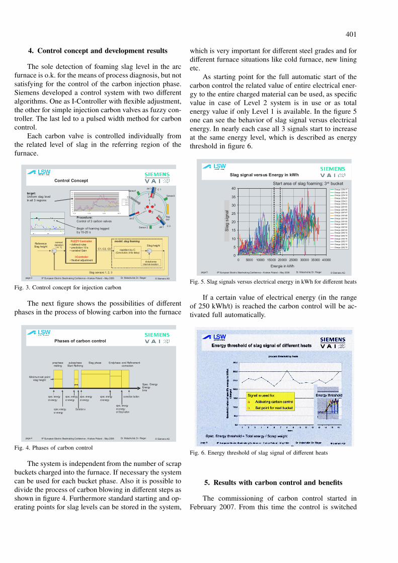
4. Control concept and development results
The sole detection of foaming slag level in the arc
furnace is o.k. for the means of process diagnosis, but not
satisfying for the control of the carbon injection phase.
Siemens developed a control system with two different
algorithms. One as I-Controller with flexible adjustment,
the other for simple injection carbon valves as fuzzy con-
troller. The last led to a pulsed width method for carbon
control.
Each carbon valve is controlled individually from
the related level of slag in the referring region of the
furnace.
page 3 9th European Electric Steelmaking Conference – Krakow Poland – May 2008 © Siemens AGDr. Matschullat, Dr. Rieger
Control Concept
0
5
1 0
1 5
2 0
2 5
3 0
3 5
4 0
4 5
11 20 12 20 13 20 142 0
Ks1
Ks2
Ks3
ReferenceSlag height
+-
normeddeviation
(+/- 1)
+-
disturbanceinternal reaction
Slag height
model: slag foaming
C1, C2, C3
FUZZY Controller
• defined rules• prediction 10 s• variabel Gain
I-Controler
• f lexibel adjustment
reaktion by C(Convolution, time delay)
Slag sensors 1, 2, 3
target:Uniform slag level
In all 3 regions
Procedure:
Control of 3 carbon valves
Begin of foaming lagged
by 15-20 s
Slag-door
Sensor3
1
Jet 1 C 3
Jet 2
Jet 3 C 1
C2
Sensor1
Sensor 2
3
2
Fig. 3. Control concept for injection carbon
The next figure shows the possibilities of different
phases in the process of blowing carbon into the furnace
page 4 9th European Electric Steelmaking Conference – Krakow Poland – May 2008 © Siemens AGDr. Matschullat, Dr. Rieger
Phases of carbon control
Minimum set pointslag height
prephasemelting
pulsephaseStart Refining
Slag phase Endphase end Refinementcorrection
Spec. EnergyEnergytime
spec. energy
or energy
spec. energy
or energy
Duration s
spec. energy
or energy
spec. energy
orenergy
spec. energy
or energyor Stop button
correction buttonspec. energy
or energy
Fig. 4. Phases of carbon control
The system is independent from the number of scrap
buckets charged into the furnace. If necessary the system
can be used for each bucket phase. Also it is possible to
divide the process of carbon blowing in different steps as
shown in figure 4. Furthermore standard starting and op-
erating points for slag levels can be stored in the system,
which is very important for different steel grades and for
different furnace situations like cold furnace, new lining
etc.
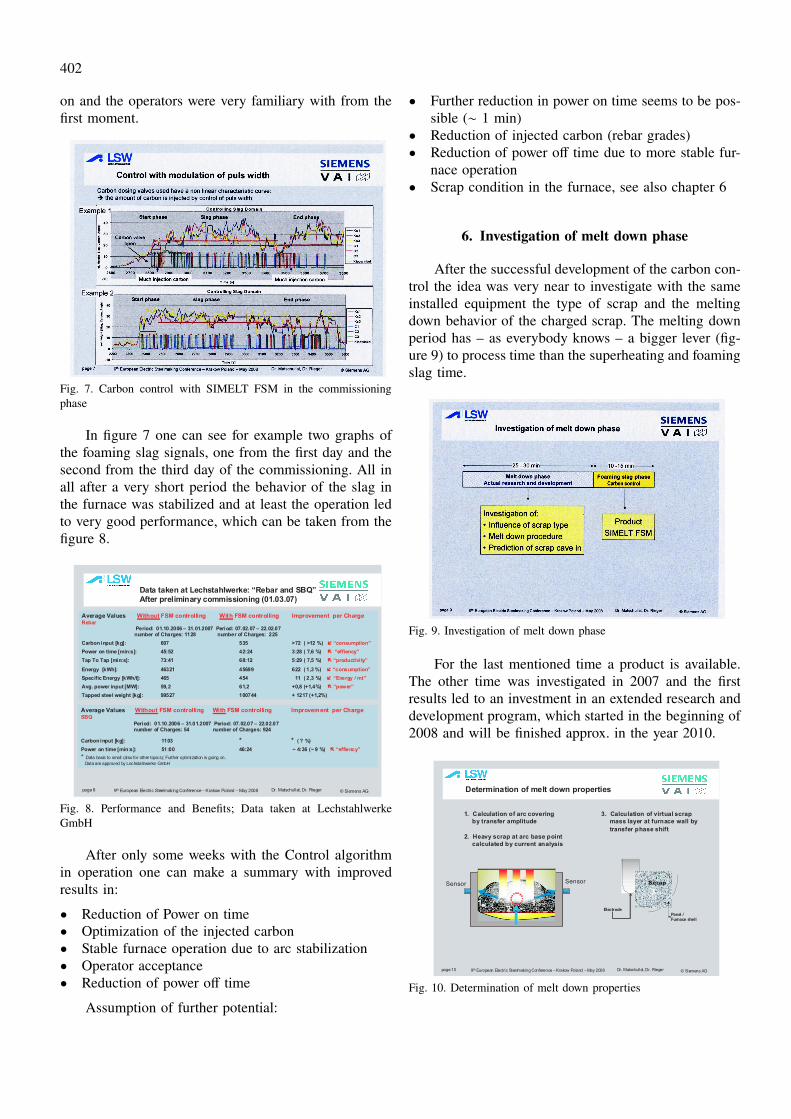
As starting point for the full automatic start of the
carbon control the related value of entire electrical ener-
gy to the entire charged material can be used, as specific
value in case of Level 2 system is in use or as total
energy value if only Level 1 is available. In the figure 5
one can see the behavior of slag signal versus electrical
energy. In nearly each case all 3 signals start to increase
at the same energy level, which is described as energy
threshold in figure 6.
page 5 9th European Electric Steelmaking Conference – Krakow Poland – May 2008 © Siemens AGDr. Matschullat, Dr. Rieger
Slag signal versus Energy in kWh
0
5
10
15
20
25
30
35
40
0 5000 10000 15000 20000 25000 30000 35000 40000
Energie in kWh
Körp
er-
Sch
lacke
nsi
gnal
Charge 225417
Charge 225418
Charge 225419
Charge 225420
Charge 225421
Charge 225422
Charge 226165
Charge 226166
Charge 226167
Charge 226168
Charge 226189
Charge 226190
Charge 226191
Charge 226192
Charge 226193
Charge 226214
Charge 226215
Charge 226216
Charge 226217
Charge 226218
Charge 226219
Sla
gsig
nal
Start area of slag foaming; 3rd bucket
Fig. 5. Slag signals versus electrical energy in kWh for different heats
If a certain value of electrical energy (in the range
of 250 kWh/t) is reached the carbon control will be ac-
tivated full automatically.
Fig. 6. Energy threshold of slag signal of different heats
5. Results with carbon control and benefits
The commissioning of carbon control started in
February 2007. From this time the control is switched
402
on and the operators were very familiary with from the
first moment.
Fig. 7. Carbon control with SIMELT FSM in the commissioning
phase
In figure 7 one can see for example two graphs of
the foaming slag signals, one from the first day and the
second from the third day of the commissioning. All in
all after a very short period the behavior of the slag in
the furnace was stabilized and at least the operation led
to very good performance, which can be taken from the
figure 8.
page 8 9th European Electric Steelmaking Conference – Krakow Poland – May 2008 © Siemens AGDr. Matschullat, Dr. Rieger
Data taken at Lechstahlwerke: “Rebar and SBQ”After preliminary commissioning (01.03.07)
Average Values Without FSM controlling With FSM controlling Improvement per ChargeRebar
Period: 01.10.2006 – 31.01.2007 Period: 07.02.07 – 22.02.07number of Charges: 1128 number of Charges: 225
Carbon input [kg]: 607 535 >72 ( >12 %) í “consumption”
Power on time [min:s]: 45:52 42:24 3:28 ( 7,6 %) ë “effiency”
Tap To Tap [min:s]: 73:41 68:12 5:29 ( 7,5 %) ë “productivity”
Energy [kWh]: 46321 45699 622 ( 1,3 %) í “consumption”
Specific Energy [kWh/t]: 465 454 11 ( 2,3 %) í “Energy / mt”
Avg. power input [MW]: 59,2 61,2 +0,8 (+1,4%) ë “power”
Tapped steel weight [kg]: 99527 100744 + 1217 (+1,2%)
Average Values Without FSM controlling With FSM controlling Improvement per ChargeSBQ
Period: 01.10.2006 – 31.01.2007 Period: 07.02.07 – 22.02.07number of Charges: 54 number of Charges: 924
Carbon input [kg]: 1103 * * ( ? %)
Power on time [min:s]: 51:00 46:24 ~ 4:36 (~ 9 %) ë “effiency”
* Data basis to small (also for other topics); Further optimization is going on.
Data are approved by Lechstahlwerke GmbH
Fig. 8. Performance and Benefits; Data taken at Lechstahlwerke
GmbH
After only some weeks with the Control algorithm
in operation one can make a summary with improved
results in:
• Reduction of Power on time
• Optimization of the injected carbon
• Stable furnace operation due to arc stabilization
• Operator acceptance
• Reduction of power off time
Assumption of further potential:
• Further reduction in power on time seems to be pos-
sible (∼ 1 min)
• Reduction of injected carbon (rebar grades)
• Reduction of power off time due to more stable fur-
nace operation
• Scrap condition in the furnace, see also chapter 6
6. Investigation of melt down phase
After the successful development of the carbon con-
trol the idea was very near to investigate with the same
installed equipment the type of scrap and the melting
down behavior of the charged scrap. The melting down
period has – as everybody knows – a bigger lever (fig-
ure 9) to process time than the superheating and foaming
slag time.
Fig. 9. Investigation of melt down phase
For the last mentioned time a product is available.
The other time was investigated in 2007 and the first
results led to an investment in an extended research and
development program, which started in the beginning of
2008 and will be finished approx. in the year 2010.
page 10 9th European Electric Steelmaking Conference – Krakow Poland – May 2008 © Siemens AGDr. Matschullat, Dr. Rieger
Determination of melt down properties
3. Calculation of virtual scrap
mass layer at furnace wall by
transfer phase shift
1. Calculation of arc covering
by transfer amplitude
Scrap
Panel /Furnace shell
Electrode
3Sensor
1 12
Sensor
2. Heavy scrap at arc base point
calculated by current analysis
Fig. 10. Determination of melt down properties

403
In the first investigations defined scrap charges were
melted down. After evaluation of the measured signal
from vibration sensors and the current three different,
but consecutive calculation methods (figure 10) describe
the procedure of scrap melt down very well.
These methods describe 3 different situations:
Method 1: The charged scrap covers the electrical
arc and influences the vibration transmission to the sen-
sor at the furnace panel. The calculation is done by the
transfer amplitude.
Method 2: The “heavy scrap” at arc base point is
calculated by the current analysis. “Heavy scrap” at arc
base point means nothing else than an agglomeration of
partially melted and caved scrap.
Method 3: Calculation of virtual scrap mass layer at
the furnace wall by transfer phase shift.
In figure 11 one can see an example for the arc
covering. The signals were translated to an arc covering
factor, what can be compared to the inverse covering of
foaming slag. On phase No. 1 a free burning arc was
detected.
page 11 9th European Electric Steelmaking Conference – Krakow Poland – May 2008 © Siemens AGDr. Matschullat, Dr. Rieger
Arc Covering, free burning arc
0%
10%
20%
30%
40%
50%
60%
70%
80%
90%
100%
0 10 20 30 40 50 60
Zeit in min
Lic
htb
oge
ne
inhü
llung
Strang 1
Strang 2
Strang 3
Arc phase 1
Free burning in front of the panel
Arc
Cove
rin
g
Time in min
Fig. 11. Basic record with qualitatively slag height and actual distri-
bution of slag in the furnace
Fig. 12. Typical scenario of scrap movement leading to scrap cave in
and free burning arcs
All in all the combination of these 3 methods includ-
ing the current root square method is able to describe a
typical scenario of scrap movement and melting down,
which is shown in figure 12.
As can be seen from this figure, scrap detaches from
the furnace panel (sensor 3) (method 3), scrap accumu-
lates at the arc base point (method 2; phases 1-3) and
the arc is burning free at the panel (method 1; phase 1)
7. Summary
The benefits of the foaming slag manager show en-
couraging results. The SIMELT FSM (Foaming Slag
Manager) is either available as module of the SIMELT
electrode control system or as stand alone product, which
also fits to other controllers or furnace automation sys-
tems than Siemens. 3.5 min reduction in power on time
and 2 min in power off time show the encouraging results
of the system.
The development of the scrap melt down mechanism
model is just at a beginning. It shows new possibilities
for diagnosis. But in the future not only diagnosis is
the target; also the creation of measures to the process
itself will be developed. More and more it seems to be
possible to operate the furnace in an entire automatic
mode.
REFERENCES
[1] W. W i c h e r t, Th. M a t s c h u l l a t, D. R i e g e r,
Foaming slag in more dimensions – A new detection
method with carbon control, AISTECH May 2007, In-
dianapolis, USA.
[2] T. M a t s c h u l l a t, W. W i c h e r t, D. R i e g e r,
K. K r u g e r, New method of measuring the level of
foaming slag in arc furnaces – or foaming slag in more
dimensions, Seminario de automacion da ABM, plenary
report; October 2007 Porto Alegre, Brasil.
[3] Th. M a t s c h u l l a t, Slag detective, Siemens, Metals
and Mining 1; 29-31 (2006).
[4] W. W i c h e r t, Th. M a t s c h u l l a t, D. R i e g e r,
The electric arc furnace fully under control. 4th. China
international steel congress, April 2006, Beijing, China.
Received: 3 April 2008.