U.S. National Report on CPT - Georgia Institute of...
16
U.S. National Report on CPT Proceedings, International Symposium on Cone Penetration Testing, Vol. 1 (CPT95), Swedish Geotechnical Society Report 3:95, Linkping, 263-276. Paul W. Mayne Jay A. Auxt Georgia Tech, Atlanta, Georgia Hogentogler & Company, Columbia, Maryland James K. Mitchell Recep Yilmaz Virginia Tech, Blacksburg, Virginia Fugro USA, Houston, Texas SYNOPSIS: Over the two decades since its introduction into the United States, the CPT has now established its position as a routine, reliable, and expedient means for site characterization, stratigraphic profiling, evaluation of soil engineering parameters, and geotechnical design. Piezocones provide measurements of penetration pore water pressures either midface (type 1) or at the shoulder (type 2). The latter is necessary for the proper correction of tip resistance in soft soils, while the former provides better resolution and detailing in stiff fissured materials. Most areas of the U.S. are now serviced by specialty firms with cone trucks for optimizing production, penetration depths, and areal coverage. Portable cone systems are available for small projects and remote locations. Research on CPT testing and analysis continues to have high priority within many organizations. The incorporation of additional sensors has increased cone versatility, thus favoring use of seismic- geophones, resistivity- or conductivity-, natural gamma-, and chemical-cones. This is attractive on geoenvironmental projects for expedient contaminant mapping while minimizing site damage and wastes generated from testing. 1. GEOLOGICAL REGIONS The vast expanse of the United States of America includes many complex, mixed, and varied geomorphological formations throughout the 50 states. An overview of the surficial geologies of the U.S. is given by Hunt (1986). While CPT is not possible in the very rocky and mountainous regions of the country, the test is very applicable to the coastal regions, inland sedimentary deposits, residual soil types, as well as reclaimed lands formed from hydraulic fills, dredgings, and mine tailings. The cone has become particularly popular for use in the marine sediments of the Atlantic and Pacific Coastal Plain Provinces, the deltaic and marine sediments of the Gulf states, glacial lacustrine deposits around the Great Lakes to New England, and floodplain alluvium from the Great Plains and following the Mississippi River. Throughout these regions, a number of specialized testing firms with cone trucks or trailers to provide CPT services. 2. TYPES OF PENETRATION TESTING Penetration tests common to U.S. practice include the standard penetration test (SPT) and cone penetration test (CPT). In some regions, the flat blade dilatometer test (DMT) is used. Testing procedures for these three tests are essentially standardized, for the most part, excepting local practices that accommodate a the specific geology or needs of the region. Other kinds of penetration tests are employed throughout the U.S., but are unique and localized to certain parts of the country. For example, a variety of dynamic cones and driven penetrometers (Texas Highway-type, Sowers drive cone, Michigan-state, Dinastar), and large split-barrel type samplers (D&M,
Transcript of U.S. National Report on CPT - Georgia Institute of...
U.S. National Report on CPTProceedings, International Symposium on Cone Penetration Testing, Vol. 1 (CPT�95), Swedish Geotechnical SocietyReport 3:95, Linköping, 263-276.
Paul W. Mayne Jay A. AuxtGeorgia Tech, Atlanta, Georgia Hogentogler & Company, Columbia, Maryland
James K. Mitchell Recep YilmazVirginia Tech, Blacksburg, Virginia Fugro USA, Houston, Texas
SYNOPSIS: Over the two decades since its introduction into the United States, the CPT has now establishedits position as a routine, reliable, and expedient means for site characterization, stratigraphic profiling,evaluation of soil engineering parameters, and geotechnical design. Piezocones provide measurements ofpenetration pore water pressures either midface (type 1) or at the shoulder (type 2). The latter is necessary forthe proper correction of tip resistance in soft soils, while the former provides better resolution and detailing instiff fissured materials.
Most areas of the U.S. are now serviced by specialty firms with cone trucks for optimizing production,penetration depths, and areal coverage. Portable cone systems are available for small projects and remotelocations. Research on CPT testing and analysis continues to have high priority within many organizations.
The incorporation of additional sensors has increased cone versatility, thus favoring use of seismic-geophones, resistivity- or conductivity-, natural gamma-, and chemical-cones. This is attractive ongeoenvironmental projects for expedient contaminant mapping while minimizing site damage and wastesgenerated from testing.
1. GEOLOGICAL REGIONS
The vast expanse of the United States ofAmerica includes many complex, mixed, andvaried geomorphological formationsthroughout the 50 states. An overview of thesurficial geologies of the U.S. is given by Hunt(1986).
While CPT is not possible in the very rockyand mountainous regions of the country, thetest is very applicable to the coastal regions,inland sedimentary deposits, residual soiltypes, as well as reclaimed lands formed fromhydraulic fills, dredgings, and mine tailings.The cone has become particularly popular foruse in the marine sediments of the Atlantic andPacific Coastal Plain Provinces, the deltaic andmarine sediments of the Gulf states, glaciallacustrine deposits around the Great Lakes toNew England, and floodplain alluvium fromthe Great Plains and following the Mississippi
River. Throughout these regions, a number ofspecialized testing firms with cone trucks ortrailers to provide CPT services.
2. TYPES OF PENETRATION TESTING
Penetration tests common to U.S. practiceinclude the standard penetration test (SPT) andcone penetration test (CPT). In some regions,the flat blade dilatometer test (DMT) is used.Testing procedures for these three tests areessentially standardized, for the most part,excepting local practices that accommodate athe specific geology or needs of the region.
Other kinds of penetration tests areemployed throughout the U.S., but are uniqueand localized to certain parts of the country.For example, a variety of dynamic cones anddriven penetrometers (Texas Highway-type,Sowers drive cone, Michigan-state, Dinastar),and large split-barrel type samplers (D&M,
Converse, Acker, California-type) is used thatare similar in concept to the SPT. However,the cone/spoon diameters, hammer sizes, anddriving forces of these devices are notstandardized, except perhaps within a givenlocality.
For gravelly soils, the Becker penetrationtest (BPT) has been developed and primarilyutilized in western North America. Initiallydeveloped for use in assessing pile driveabilityand design of pile lengths in very coarsedeposits, the BPT has also proved useful inevaluating liquefaction potential (e.g., Sy &Campanella 1994).
3. CPT EQUIPMENT
Most serious CPT work in the U.S. is nowperformed using standard electronic coneshaving a 60° apex pushed continuously at 20mm/s, essentially making the mechanical vers-ions obsolete. Initial designs that required theamplification of electric cone outputs, havenow been replaced with superior electronicswithin the cone using signal conditioning toprovide better resolution, increased reliability,and minimal noise.
Data acquisition systems typically includea portable computer, analog-digital converter,storage media (hard drive, floppy drives), andstrip chart recorder or printer.
3.1 Penetrometers and rigs
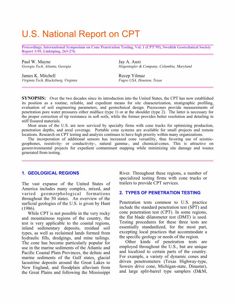
Penetrometers having diameters of either 35.7mm (10 cm2 projected area) and 43.7 mm (15cm2) are used routinely. Because of thesuperior stratigraphic detailing, much CPT isaccomplished with piezocones (designatedPCPT or CPTU). As shown in Fig. 1, twobasic types of piezocones are used for routinesite investigations: (1) one with midfaceelement for pore water pressure measurements(designated u1 or ut), and (2) with shoulder orbehind the tip position (u2 or ubt). Earlierversions of the type 1 design placed theelement at the cone apex. However, laterdesigns put the element midface because it isless vulnerable to damage and excessive wear.
There are advantages and disadvantagesassociated with either type 1 or 2 cones. Pore-water pressure readings from type 2 cones are
Fig. 1. Various Penetrometers (bottom to top):Miniature 4 cm2 Electric Cone; 10 cm2 Type 2Piezocone (shoulder element); Type 1 (midface)piezocones; Type 2 Seismic, Hogentogler Dual Type1 & 2 Seismic; 15 cm2 Fugro Triple-Element Cone.
necessary for the proper correction of meas-ured cone tip resistances (qc 6 qT), as perCampanella & Robertson (1988) and DeBeeret al. (1988). This correction is very importantin soft to medium stiff intact clays, but notsignificant in medium to dense clean sands oroverconsolidated fissured clays where smallpositive, zero, or even negative )u2 readingsare obtained (Mayne et al. 1990).
In general, type 2 cones may be moreappropriate to the northern regions of the U.S.because of the preponderance of near surfacerecent geologic deposits comprised of soft tofirm lightly overconsolidated soils, includingmarine deposits of the Atlantic coastal plain(e.g, Boston Blue clay; Calvert clay), glaciallacustrine sediments of the Great Lakes, andalluvial deposits. Maximum detailing isaccom-plished using type 1 cones, however,and if stratigraphic profiling is paramount, u1measurements may be preferred.
In contrast, the hot temperate climate of thesouthern U.S. has formed overconsolidatedand stiff materials by desiccation (e.g.,Florida, Lousiana Southern California). If thematerials are fissured, little detail is observedwith type 2 readings and u2 measurements canbe small or even negative. Thus, a type 1 conemay be of better value in profiling. On theother hand, some difficulties have been notedin smearing and clogging of type 1 face porouselements during penetration of fat plasticclays, e.g. the Beaumont clays of Texas. In
this case, less smearing occurs with a type 2cone. Of course, exceptions to the abovegeographic generalities occur, and hard OCCretaceous clays can also be found in thenorthern U.S. (e.g., Washington, DC), as wellas the presence of very soft deltaic sedimentsin the south (e.g., offshore Gulf of Mexico).Thus, an ideal scenario for general use wouldbe a dual-element cone for site characterization(Juran & Tumay 1989).
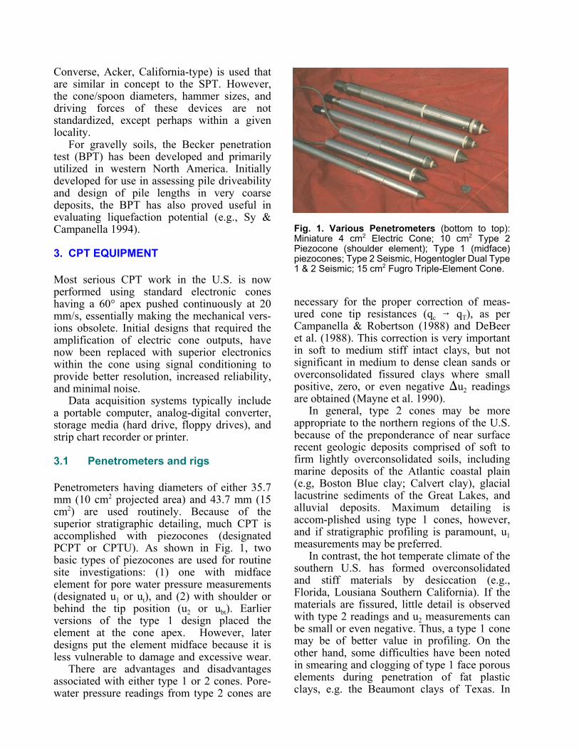
In order to maximize production andefficiency, most regions of the U.S. are nowserviced by commercial testing firms andresearch institutions with specialized conetrucks (e.g., see Fig. 2). Compared with aconventional 10-tonne drill rig, a standard conetruck weighs about 20-tonnes, although special30- and 40-tonne models have been built thatuse stronger rods in order to successfullypenetrate dense sands or facilitate thecompletion of soundings with penetrationdepths of up to 60 m or more.
Fig. 2. Cone Truck operated by FugroGeosciences Conducting CPTUs at Georgia TechCivil & Environmental Engrg. Building.
During CPT, depth increments are measuredabove ground using either potentiometers,depth wheels, or ultrasonic beams. Successiveincrements are summed to give the total depth.Although cableless systems are available(Larsson & Mulabdiƒ 1991), almost all U.S.systems employ a cable through the rods toconnect the cone to the data acquisition unit atthe ground surface.
3.2 Testing & calibration procedures.
Electronic penetrometers require a minimumof two calibration procedures: (1) load cellcali-bration in a compression apparatus toobtain output voltage for qc and fs; and (2)hydrostatic calibration in a triaxial cell fordetermination of output voltage for u1 or u2, aswell as the net area ratios for correction of tip(qT) and sleeve (fT) resistances. Details onthese calibrations have been given elsewhere(e.g., Jamiolkowski et al. 1985; DeBeer et al.1988). If the cone will be used in very cold orvery hot climates, a calibration check fortemperature variations is also recommended(Lunne et al. 1986).
Calibrations of ancillary devices such aspotentiometers for depth measurements andoscilloscopes for seismic velocity arrival timesare handled separately.
Porous elements are often made of flexiblepolypropylene and are disposed of after eachsounding. In stiff or dense soils, stainless steelor rigid ceramic elements are better for type 1cones because of high abrasion and thecompressibility of the filter affects the porepressure readings (Campanella & Robertson1988).
Proper saturation of the porous element isimportant for quality results (Lunne et al.1986). A 50/50 mixture of glycerine and waterprovides excellent results, although sometesting firms use either silicon oil or distilledwater. A prophylactic is placed over thesaturated cone with a rubber band to maintainsaturation until penetration.
3.3 Corrections & data presentation
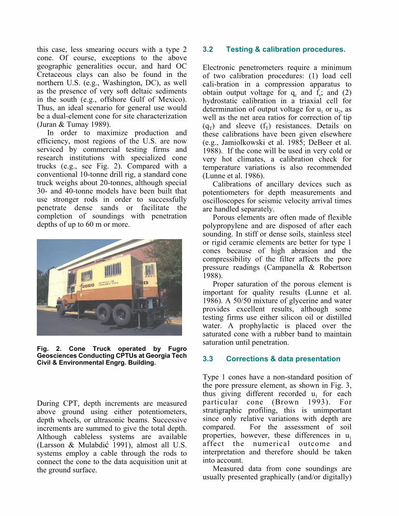
Type 1 cones have a non-standard position ofthe pore pressure element, as shown in Fig. 3,thus giving different recorded u1 for eachparticular cone (Brown 1993). Forstratigraphic profiling, this is unimportantsince only relative variations with depth arecompared. For the assessment of soilproperties, however, these differences in u1affect the numerical outcome andinterpretation and therefore should be takeninto account.
Measured data from cone soundings areusually presented graphically (and/or digitally)
Fig. 3. Porous element positions: (a) general; and(b) specific or "rainbow" cone (Brown 1993).
in terms of the individual readings versusdepth, including: cone tip resistance (qc or qT),sleeve friction (fs or fT), and penetration porepressure (u1 or u2 or excess )u). Sometimes, anadditional profile of dynamic pore pressure,u/qc, or the normalized piezocone parameter,Bq = )u/(qT-Fvo), is presented (Wroth 1984).
Figure 4 illustrates an example profilesummary of qT, fs, and u from single-, dual-,and triple-element soundings in overconsol-idated desiccated clay in Baton Rouge,Louisiana. Note the u3 position is locatedbehind the friction sleeve. Excellent repeata-bility of results is evident for the first threechannels, while differences are observed forthe two trailing pore pressure locations, thusinferring difficulties in maintaining saturation.
If piezocone dissipation tests at specific testdepths are made, the results are presented witheither penetration pore pressure (u) or excess)u versus time or logarithm of time (e.g.,Levadoux & Baligh 1986).
For seismic cone soundings, a downholeassessment of the time arrivals of thecompression (P) and shear (S) waves can be
obtained, thus producing profiles of theinterpreted P- and S-wave velocities vs. depth(Campanella 1994). Usually, these data arepresented at discrete increments correspondingto rod changes (approx. each meter). Alter-natively, the complete wave trace record withtime (forward and/or reverse) can be shownfor each event.
If a conductivity cone is used (Campanella& Weemes 1990), a continuous profile ofelectrical resistivity is presented and used toinfer the presence of subsurface contaminants.
3.4 National standards
Standard procedures for CPT have beenestablished by ASTM D-3441 since 1975 thataddressed mechanical and electrical frictioncones. For the piezocone test, a revised ASTMD-3441 procedure has been proposed in whicha type 2 porous element position is recom-mended (Farrar 1995).
4. INTERPRETATION
The results of CPT and PCPT are used fordelineating soil strata and for evaluating thegeotechnical engineering parameters of thesubsurface layers. In recent environmentalapplications, cone data are used to infer ordetect the presence of anomalies such ascontaminants in the pore fluid.
4.1 Soil classification and stratigraphy
Piezocone results are unsurpassed in thedetail-ing of soil stratigraphy. Exceptionalresolution makes the detection of thin seamsand lenses possible, particularly via the porepressure channel. This facet is very importantfrom a geoenvironmental viewpoint and forslope stability evaluations.
Soil classification using CPT and PCPTdata is indirect and relies entirely on empiricalcharts for interpretation of strata (see Table 1).
4.2. Engineering parameters
Considerable effort has been made to derivesoil engineering properties from the results ofcone and piezocone data. Methodologies have
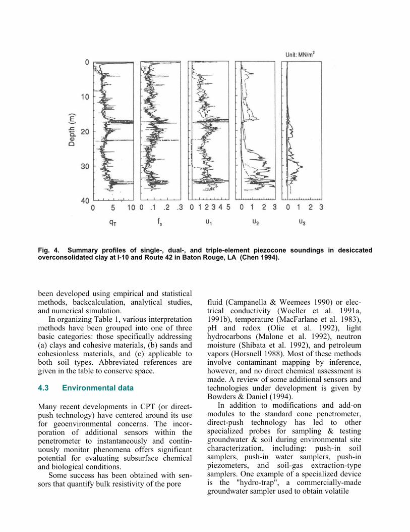
Fig. 4. Summary profiles of single-, dual-, and triple-element piezocone soundings in desiccatedoverconsolidated clay at I-10 and Route 42 in Baton Rouge, LA (Chen 1994).
been developed using empirical and statisticalmethods, backcalculation, analytical studies,and numerical simulation.
In organizing Table 1, various interpretationmethods have been grouped into one of threebasic categories: those specifically addressing(a) clays and cohesive materials, (b) sands andcohesionless materials, and (c) applicable toboth soil types. Abbreviated references aregiven in the table to conserve space.
4.3 Environmental data
Many recent developments in CPT (or direct-push technology) have centered around its usefor geoenvironmental concerns. The incor-poration of additional sensors within thepenetrometer to instantaneously and contin-uously monitor phenomena offers significantpotential for evaluating subsurface chemicaland biological conditions.
Some success has been obtained with sen-sors that quantify bulk resistivity of the pore
fluid (Campanella & Weemees 1990) or elec-trical conductivity (Woeller et al. 1991a,1991b), temperature (MacFarlane et al. 1983),pH and redox (Olie et al. 1992), lighthydrocarbons (Malone et al. 1992), neutronmoisture (Shibata et al. 1992), and petroleumvapors (Horsnell 1988). Most of these methodsinvolve contaminant mapping by inference,however, and no direct chemical assessment ismade. A review of some additional sensors andtechnologies under development is given byBowders & Daniel (1994).
In addition to modifications and add-onmodules to the standard cone penetrometer,direct-push technology has led to otherspecialized probes for sampling & testinggroundwater & soil during environmental sitecharacterization, including: push-in soilsamplers, push-in water samplers, push-inpiezometers, and soil-gas extraction-typesamplers. One example of a specialized deviceis the "hydro-trap", a commercially-madegroundwater sampler used to obtain volatile
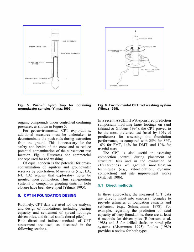
Fig. 5. Push-in hydro trap for obtaininggroundwater samples (Yilmaz 1995).
organic compounds under controlled confiningpressures, as shown in Figure 5.
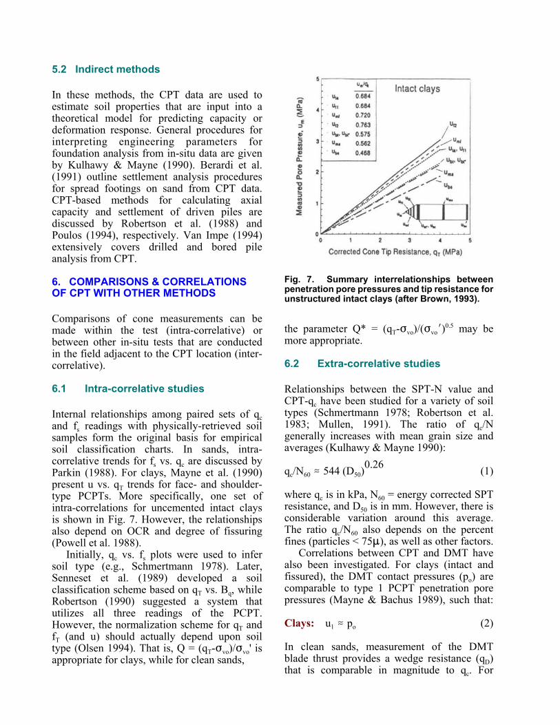
For geoenvironmental CPT explorations,additional measures must be undertaken todecontaminate the push rods during extractionfrom the ground. This is necessary for thesafety and health of the crew and to reducepotential contamination of the subsequent testlocation. Fig. 6 illustrates one commercialconcept used for rod washing.
Of equal concern is the potential for cross-contamination of aquifers and groundwaterreserves by penetration. Many states (e.g., LA,NJ, CA) require that exploratory holes begrouted upon completion. Thus, self-groutingsystems or companion grouting units for holeclosure have been developed (Yilmaz 1995).
5. CPT IN FOUNDATION DESIGN
Routinely, CPT data are used for the analysisand design of foundations, including bearingcapacity and settlement of spread footings,driven piles, and drilled shafts (bored piles).Both direct and indirect methods of CPTassessment are used, as discussed in thefollowing sections.
Fig. 6. Environmental CPT rod washing system(Yilmaz 1995).
In a recent ASCE/FHWA-sponsored predictionsymposium involving large footings on sand(Briaud & Gibbens 1994), the CPT proved tobe the most preferred test (used by 30% ofpredictors) for assessing the foundationperformance, as compared with 25% for SPT,16% for PMT, 14% for DMT, and 10% fortriaxial tests.
The CPT is also useful in assessingcompaction control during placement ofstructural fills and in the evaluation ofeffectiveness of ground modificationtechniques (e.g., vibroflotation, dynamiccompaction) and site improvement works(Mitchell 1986).
5.1 Direct methods
In these approaches, the measured CPT dataare directly input into empirical formulas toprovide estimates of foundation capacity andsettlement (e.g., Schmertmann 1978). Forexample, regarding the prediction of axialcapacity of deep foundations, there are at least6 methods for driven piles (Robertson et al.1988) and 5 for drilled shafts or bored pilesystems (Alsammam 1995). Poulos (1989)provides a review for both types.
5.2 Indirect methods
In these methods, the CPT data are used toestimate soil properties that are input into atheoretical model for predicting capacity ordeformation response. General procedures forinterpreting engineering parameters forfoundation analysis from in-situ data are givenby Kulhawy & Mayne (1990). Berardi et al.(1991) outline settlement analysis proceduresfor spread footings on sand from CPT data.CPT-based methods for calculating axialcapacity and settlement of driven piles arediscussed by Robertson et al. (1988) andPoulos (1994), respectively. Van Impe (1994)extensively covers drilled and bored pileanalysis from CPT.
6. COMPARISONS & CORRELATIONSOF CPT WITH OTHER METHODS
Comparisons of cone measurements can bemade within the test (intra-correlative) orbetween other in-situ tests that are conductedin the field adjacent to the CPT location (inter-correlative).
6.1 Intra-correlative studies
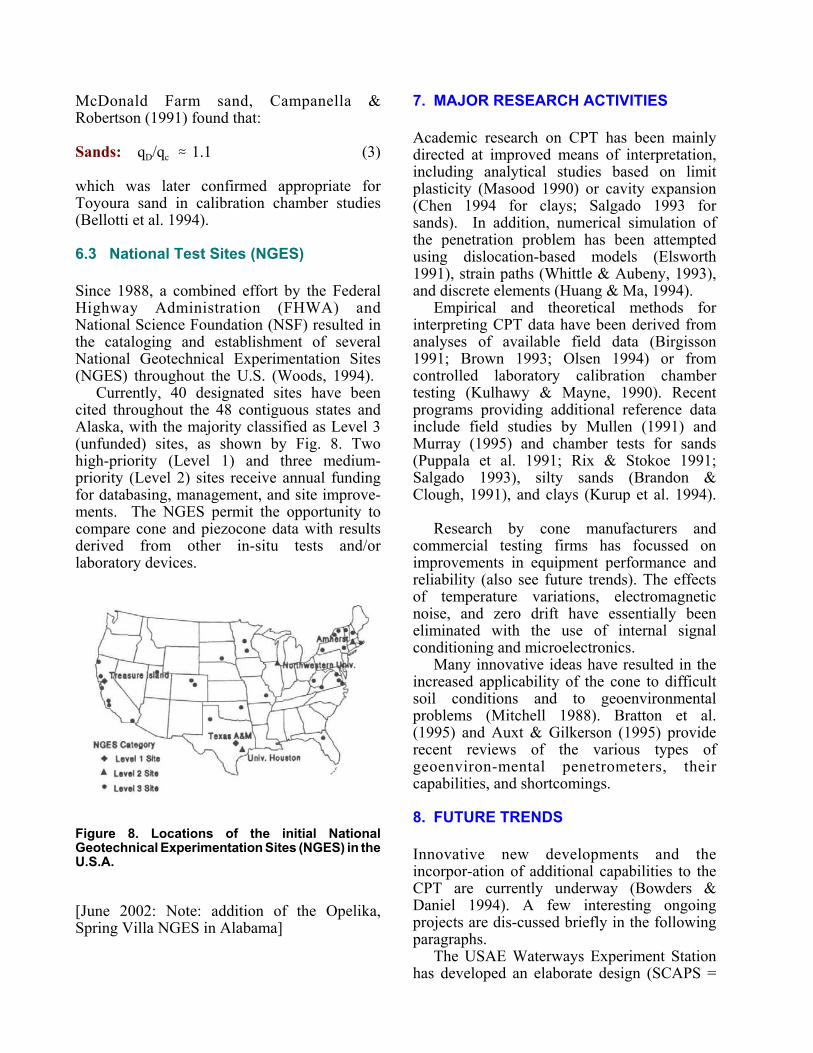
Internal relationships among paired sets of qcand fs readings with physically-retrieved soilsamples form the original basis for empiricalsoil classification charts. In sands, intra-correlative trends for fs vs. qc are discussed byParkin (1988). For clays, Mayne et al. (1990)present u vs. qT trends for face- and shoulder-type PCPTs. More specifically, one set ofintra-correlations for uncemented intact claysis shown in Fig. 7. However, the relationshipsalso depend on OCR and degree of fissuring(Powell et al. 1988).
Initially, qc vs. fs plots were used to infersoil type (e.g., Schmertmann 1978). Later,Senneset et al. (1989) developed a soilclassification scheme based on qT vs. Bq, whileRobertson (1990) suggested a system thatutilizes all three readings of the PCPT.However, the normalization scheme for qT andfT (and u) should actually depend upon soiltype (Olsen 1994). That is, Q = (qT-Fvo)/Fvo' isappropriate for clays, while for clean sands,
Fig. 7. Summary interrelationships betweenpenetration pore pressures and tip resistance forunstructured intact clays (after Brown, 1993).
the parameter Q* = (qT-Fvo)/(FvoN)0.5 may bemore appropriate.
6.2 Extra-correlative studies
Relationships between the SPT-N value andCPT-qc have been studied for a variety of soiltypes (Schmertmann 1978; Robertson et al.1983; Mullen, 1991). The ratio of qc/Ngenerally increases with mean grain size andaverages (Kulhawy & Mayne 1990):
qc/N60 . 544 (D50)0.26 (1)
where qc is in kPa, N60 = energy corrected SPTresistance, and D50 is in mm. However, there isconsiderable variation around this average.The ratio qc/N60 also depends on the percentfines (particles < 75:), as well as other factors.
Correlations between CPT and DMT havealso been investigated. For clays (intact andfissured), the DMT contact pressures (po) arecomparable to type 1 PCPT penetration porepressures (Mayne & Bachus 1989), such that:
Clays: u1 . po (2)
In clean sands, measurement of the DMTblade thrust provides a wedge resistance (qD)that is comparable in magnitude to qc. For
McDonald Farm sand, Campanella &Robertson (1991) found that:
Sands: qD/qc . 1.1 (3)
which was later confirmed appropriate forToyoura sand in calibration chamber studies(Bellotti et al. 1994).
6.3 National Test Sites (NGES)
Since 1988, a combined effort by the FederalHighway Administration (FHWA) andNational Science Foundation (NSF) resulted inthe cataloging and establishment of severalNational Geotechnical Experimentation Sites(NGES) throughout the U.S. (Woods, 1994).
Currently, 40 designated sites have beencited throughout the 48 contiguous states andAlaska, with the majority classified as Level 3(unfunded) sites, as shown by Fig. 8. Twohigh-priority (Level 1) and three medium-priority (Level 2) sites receive annual fundingfor databasing, management, and site improve-ments. The NGES permit the opportunity tocompare cone and piezocone data with resultsderived from other in-situ tests and/orlaboratory devices.
Figure 8. Locations of the initial NationalGeotechnical Experimentation Sites (NGES) in theU.S.A.
[June 2002: Note: addition of the Opelika,Spring Villa NGES in Alabama]
7. MAJOR RESEARCH ACTIVITIES
Academic research on CPT has been mainlydirected at improved means of interpretation,including analytical studies based on limitplasticity (Masood 1990) or cavity expansion(Chen 1994 for clays; Salgado 1993 forsands). In addition, numerical simulation ofthe penetration problem has been attemptedusing dislocation-based models (Elsworth1991), strain paths (Whittle & Aubeny, 1993),and discrete elements (Huang & Ma, 1994).
Empirical and theoretical methods forinterpreting CPT data have been derived fromanalyses of available field data (Birgisson1991; Brown 1993; Olsen 1994) or fromcontrolled laboratory calibration chambertesting (Kulhawy & Mayne, 1990). Recentprograms providing additional reference datainclude field studies by Mullen (1991) andMurray (1995) and chamber tests for sands(Puppala et al. 1991; Rix & Stokoe 1991;Salgado 1993), silty sands (Brandon &Clough, 1991), and clays (Kurup et al. 1994).
Research by cone manufacturers andcommercial testing firms has focussed onimprovements in equipment performance andreliability (also see future trends). The effectsof temperature variations, electromagneticnoise, and zero drift have essentially beeneliminated with the use of internal signalconditioning and microelectronics.
Many innovative ideas have resulted in theincreased applicability of the cone to difficultsoil conditions and to geoenvironmentalproblems (Mitchell 1988). Bratton et al.(1995) and Auxt & Gilkerson (1995) providerecent reviews of the various types ofgeoenviron-mental penetrometers, theircapabilities, and shortcomings.
8. FUTURE TRENDS
Innovative new developments and theincorpor-ation of additional capabilities to theCPT are currently underway (Bowders &Daniel 1994). A few interesting ongoingprojects are dis-cussed briefly in the followingparagraphs.
The USAE Waterways Experiment Stationhas developed an elaborate design (SCAPS =
site characterization and analysis penetrometersystem) that includes a fiber-optics guide froma sapphire window located near the cone tip tomeasure the laser-induced fluorescence (LIF)of petroleum chemicals which may be present(Schroeder et al. 1991; Stark, 1991). A similarsystem using a fiber optic chemical sensor(FOCS) and photo-ionization detector wasdeveloped (Leonard & Tillman 1993), but hasbeen discontinued because the sensor is notreversible. An LIF probe utilizing a tuneablelaser fluorescence system (ROST system) isnow in use for the identification of aromatichydrocarbons (Yilmaz 1995).
A miniature cone unit for expedient CPTshas been designed with a caterpillar thrustsystem and self-coiling rods that mount at thefront of a 4-wheel drive diesel pickup truck(Tumay 1994).
A new subsurface vision probe has beenproposed for direct optical soil classificationby CPT. The development will use a sapphireviewing window, high-resolution videocamera, and image processing center todetermine grain size distributions in real time(Hryciw & Raschke 1996).
9. REFERENCES
Alsamman, O.M. (1995). The use of CPT forcalculating axial capacity of drilled shafts.Phd Dissertation, University of Illinois atUrbana-Champaign, 300 p.
Auxt, J.A. and Gilkerson, R. (1995). Enviro-nmental site characterization in the U.S.using the cone. Proceedings, CPT'95, Vol.2,Linköping.
Bellotti, R., Fretti, C., Jamiolkowski, M. &Tanizawa, F. (1994), Proc. 13th Intl. Conf.on Soil Mech & Foundation Engineering(4), New Delhi, 1779-1782.
Berardi, R., Jamiolkowski, M., & Lancellotta,R. (1991). Settlement of shallow founda-tions in sands: selection of stiffness frompenetration resistance. Foundation Engin-eering Congress (I), ASCE GSP 27, NewYork, 185-200.
Birgisson, B. (1991). Reliability-based eval-uation of clay strength from the cone pene-tration test, MS Thesis, Civil Engineering,Cornell University, Ithaca, NY, 142 p.
Bowders, J. & Daniel, D.E. (1994). Cone pen-etration technol. for subsurface character-ization. Geotechnical News 12 (3), 24-29.
Brandon, T.L. and Clough, G.W. (1991).Methods of sample fabrication in the VTcalibration chamber. Calibration ChamberTesting, Elsevier, New York, 119-133.
Bratton, W.L., Bratton, J.L., and Shinn, J.D.(1995). Direct penetration technology forgeotechnical and environmental site char-acterization. Geoenvironment 2000 (1), GSP 46, ASCE, New York, 105-122.
Briaud, J-L. and Gibbens, R.M. (1994). Predicted and Measured Behavior of FiveSpread Footings on Sand (GSP 41), ASCE,New York, 255 p.
Brown, D.N. (1993). The prediction of claysoil properties using the piezocone. MSThesis, Georgia Institute of Technology,Atlanta, 168 p.
Campanella, R.G (1994). Field methods fordynamic geotechnical testing. DynamicGeotechnical Testing II (STP 1213), ASTM,Philadelphia, 3-23.
Campanella, R.G. and Robertson, P.K. (1988).Current status of the piezocone test. Pene-tration Testing 1988 (1), Balkema, Rotter-dam, 93-116.
Campanella, R.G. and Robertson, P.K. (1991).Use and interpretation of a research dila-tometer. Canadian Geotechical J. 28 (1),113-126.
Campanella, R.G., and Weemees, I. (1990). Development and use of an electrical resistivity cone for groundwater contam-ination. Canadian Geotechnical Journal27(5), 557-567.
Chen, B.S-Y. (1994). Profiling OCR in claysby dual piezocone tests. PhD Thesis, Civil& Environmental Engrg, Georgia Instituteof Technology, Atlanta, 350 p.
Chen, B.S-Y. and Mayne, P.W. (1994). Profiling the overconsolidation ratio ofclays by piezocone tests. Report GIT-CEEGEO- 94-1, Civil Engrg., GeorgiaTech, Atlanta, 280 p.
DeBeer, E.E., Goelen, E., Heynen, W. andJoustra, K. (1988). CPT: international ref-erence test procedure. Penetration Testing1988 (1), Balkema, 27-52.
Elsworth, D. (1991). Dislocation analysis ofpenetration in saturated porous media.
ASCE Journal of Engineering Mechanics 117(2), 391-408.
Farrar, J. (1995). Development of the newASTM standard for CPT and piezocone testin soils. Proceedings, CPT''95, Vol. 2, PaperA79, Linköping.
Horsnell, M.R. (1988). The use of cone penetration testing to obtain environmentaldata. Penetration Testing in the UK, Thomas Telford, London, 289-294.
Hryciw, R.D. & Raschke, S.A. (1996). Devel-opment of a computer vision technique forin-situ soil characterization. TransportationRes. Record (session on image analysis).
Huang, A-B. and Ma, M.Y. (1994). An analy-tical study of CPTs in granular materials.Canadian Geot. J. 31 (1), 91-103.
Hunt, C.B. (1986). Surficial Deposits of theUnited States. Van Nostrand Reinhold Company, New York, 189 p.
Jamiolkowsi, M., Ladd, C.C., Germaine, J. &Lancellotta, R. (1985). New developmentsin field & lab testing of soils. Proc. 11th
ICSMFE (1), San Francisco, 57-154.Juran, I. and Tumay, M.T. (1989). Soil strati-
fication using dual element piezocone. Transportation Research Record 1235,National Acad Press, 68-78.
Kulhawy, F.H. and Mayne, P.W. (1990). Manual on estimating soil properties forfoundation design. Report EL-6800, ElectricPower Research Inst., Palo Alto, 306 p.
Kurup, P.U., Voyiadjis, G.Z., and Tumay,M.T. (1994). Calibration chamber studies ofpiezocone test in cohesive soils. Journal ofGeotechnical Engineering 120 (1), 81-107.
Larsson, R. and Mulabdiƒ, M. (1991). Piezo-cone tests in clay. Report No. 42, SwedishGeotechnical Inst., Linköping, 240 p.
Levadoux, J-N. and Baligh, M.M. (1986).Consolidation after undrained piezoconepenetration. Journal of Geotechnical Engineering 112 (7), 707-745.
Leonard, L. and Tillman, N. (1993). Sensorintegration for site screening. Proceedings,3rd Intl. Symp. on Field Screening Methodsfor Hazardous Wastes, Las Vegas.
Lunne, T., Eidsmoen, T.E., Gillespie, D. andHowland, J. (1986). Laboratory and fieldcalibration of cone penetrometers. Use ofIn-Situ Tests in Geotechnical Engineering,ASCE GSP 6, 714-729.
MacFarlane, D.S., Cherry, J., Gillham, R. &Sudicky, E. (1983). Migration of contam-inants in groundwater at a landfill. Journalof Hydrology 63 (1), 1-29.
Malone, P.G., Comes, G.D., Chrestman, A.,Cooper, S.S., & Franklin, A.G. (1992).Cone penetrometer surveys of soil contam-ination. Environmental Geotechnology,Balkema, Rotterdam, 251-257.
Masood, T. (1990). Determination of lateralearth pressure in soils by in-situ measure-ment. PhD Thesis, Civil Engineering, Univ.of California, Berkeley.
Mayne, P.W. & Bachus, R.C. (1989). Pene-tration pore pressures in clay. Proc. 12th
Intl. Conf. Soil Mechanics and FoundationEngrg. (1), Rio de Janeiro, 291-294.
Mayne, P.W. and Burns, S.E. (1994). Opto-electronics geoenvironmental cone pene-trometer for detecting subsurface contam-inants. Proc., Workshop on AdvancingTechnology for Cone Penetration Testing,University of Austin, Texas.
Mitchell, J.K. (1986). Ground improvementevaluation by in-situ tests. Use of In-SituTests in Geotechnical Engineering, ASCEGSP 6, 221-236.
Mitchell, J.K. (1988). New developments inpenetration tests and equipment.Penetration Testing 1988 (1), Balkema,Rotterdam, 245-261.
Mullen, W.G. (1991). An evaluation of theutility of in-situ test methods for trans-mission foundation design. PhD Thesis,CEE, Virginia Tech, Blacksburg, 553 p.
Murray, R.F. (1995). Piezocone exploration ofmarine clay deposit at Pease Air Force
Base, MS Thesis, Univ. of New Hampshire,Durham, 254 p.
Myers, A.E. (1993). Electric cone penetro-meter as a geoenvironmental investigationtool. Proceedings, Joint Symposium of theAssociation of Engineering Geologists &American Society of Civil Engineers, Baltimore, MD, 12 p.
Olie, J.J., Van Ree, C., & Bremmer, C. (1992).In-situ measurement by chemoprobe ofgroundwater from sanitation of versaticacid spill. Geotechnique 42 (1), 13-21.
Olsen, R.S. (1994). Normalization & predict-tion of geotechnical properties using theCPT. Technical Report GL-94-29, USAE
Waterways Experiment Station, Vicksburg,MS, 322 p.
Poulos, H.G. (1989). Pile behavior: theory andapplication. Geotechnique 39 (3), 363-415.
Poulos, H.G. (1994). Settlement prediction fordriven piles and pile groups. Vertical &Horiz. Deformations of Foundations (2),ASCE GSP 40, 1629-1649.
Powell, J.J.M., Quarterman, R.S.T. & Lunne,T. (1988). Interpretation and use of thepiezocone test in UK. Penetration Testing inthe UK, Thomas Telford, London, 47-52.
Puppala, A.J., Acar, Y.B., and Tumay, M.T.(1991). Miniature CPT tests in dense Monterey sand. Calibration Chamber Testing, Elsevier, New York, 339-350.
Rix, G.J. and Stokoe, K.H. (1991). Correl-ation of initial tangent modulus and coneresistance, Calibration Chamber Testing,Elsevier, New York, 351-362.
Robertson, P.K. (1990). Soil classificationusing the CPT. Canadian Geot. J. 27 (1),151-158.
Robertson, P.K. and Campanella, R.G. (1983).Interpretation of cone penetration tests,Canadian Geotechnical J. 20 (4), 718-745.
Robertson, P.K., Campanella, R.G., and Wightman, A. (1983). SPT-CPT correl-ations. Journal of Geotechnical Engineering109 (11), 1449-1459.
Robertson, P.K, Campanella, R.G., Davies,M.P., and Sy, A. (1988). Axial capacity ofdriven piles in deltaic soils using CPT.Penetration Testing 1988 (2), Balkema, Rotterdam, 919-928.
Salgado, R. (1993). Analysis of penetrationresistance in sands. PhD Thesis, Universityof California, Berkeley, 357 p.
Schmertmann, J.H. (1978). Guidelines forCPT: performance and design. Report FHWA-TS-78-209, Federal Highway Administration, Washington DC, 145 p.
Schroeder, J.D., Booth, S.R., and Trocki, L.K. (1991). Cost effectiveness of the sitecharacterization and analysis penetrometersystem. Report LA-UR-91-4016 prepared byLos Alamos National Laboratory, NewMexico, to the Department of Energy, 46 p.
Senneset, K., Sandven, R. and Janbu, N. (1989). Evaluation of soil parameters fromPCPT. Transportation Research Record1235, Washington DC, 24-37.4
Shibata, T., Mimura, M., Shrivastava, A.K.,and Nobuyama, M. (1992). Moisture meas-urement by neutron moisture cone penetro-meter. Soils & Foundations 32 (4), 58-67.
Stark, T.D. (1991). Geotechnical engineeringat WES. Geotechnical News 9 (4), 71-75.
Stark, T.D. and Olson, S.M. (1995).Liquefaction resistance using CPT andfield case histories. Journal of GeotechnicalEngineering 121 (12), 856-869.
Sy, A. and Campanella, R.G. (1994). Becker& SPT correlations with casing friction.Canadian Geot. J. 31 (3), 343-356.
Tumay, M.T. (1994). Implementation of Louisiana electric cone penetrometer system. Rept. LA-94/280-B to Federal Highway Admin., Washington DC, 18 p.
Van Impe, W.F. (1994). Developments in pile design. Piling & Deep Foundations (2),
Balkema, Rotterdam, 727-758.Whittle, A.J. and Aubeny, C.P. (1993). The
effects of installation disturbance on interpretation of in-situ tests in clay. Predictive Soil Mechanics, Thomas Telford,London, 742-767.
Woeller, D.J., Weemees, I., and Kokan, M.(1991a). Penetrat ion test ing forgroundwater contaminants. GeotechnicalEngineering Congress, ASCE GSP 27 (1),76-87.
Woeller, D.J., Weemees, I., and Kurfurst, P.J.(1991b). Penetration testing for arctic soilconditions. Proceedings, 44th CanadianGeotechnical Conf., Calgary (1), 44.1-7.
Woods, R.D., Benoît, J. & deAlba, P. (1994).National Geotechnical ExperimentationSites. Geotechnical News 12 (1), 39-44.
Wroth, C.P. (1984). The interpretation of in-situ tests. Geotechnique 34 (4), 449-489.
Yilmaz, R. (1995). Hazardous waste site investigation. Internal Bulletin. Fugro Geosciences, Houston, TX.
US National Report on CPT - Proceedings, Symposium by Swedish Geot. Society, 1995
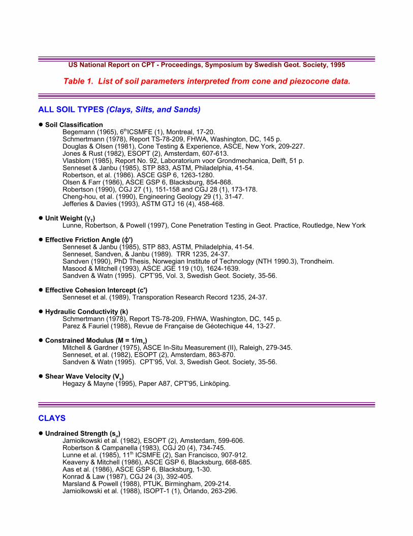
Table 1. List of soil parameters interpreted from cone and piezocone data.
ALL SOIL TYPES (Clays, Silts, and Sands)
! Soil ClassificationBegemann (1965), 6thICSMFE (1), Montreal, 17-20.Schmertmann (1978), Report TS-78-209, FHWA, Washington, DC, 145 p.Douglas & Olsen (1981), Cone Testing & Experience, ASCE, New York, 209-227.Jones & Rust (1982), ESOPT (2), Amsterdam, 607-613.Vlasblom (1985), Report No. 92, Laboratorium voor Grondmechanica, Delft, 51 p.Senneset & Janbu (1985), STP 883, ASTM, Philadelphia, 41-54.Robertson, et al. (1986). ASCE GSP 6, 1263-1280.Olsen & Farr (1986), ASCE GSP 6, Blacksburg, 854-868.Robertson (1990), CGJ 27 (1), 151-158 and CGJ 28 (1), 173-178.Cheng-hou, et al. (1990), Engineering Geology 29 (1), 31-47.Jefferies & Davies (1993), ASTM GTJ 16 (4), 458-468.
! Unit Weight ((T)Lunne, Robertson, & Powell (1997), Cone Penetration Testing in Geot. Practice, Routledge, New York
! Effective Friction Angle (N')Senneset & Janbu (1985), STP 883, ASTM, Philadelphia, 41-54.Senneset, Sandven, & Janbu (1989). TRR 1235, 24-37. Sandven (1990), PhD Thesis, Norwegian Institute of Technology (NTH 1990.3), Trondheim.Masood & Mitchell (1993), ASCE JGE 119 (10), 1624-1639.Sandven & Watn (1995). CPT�95, Vol. 3, Swedish Geot. Society, 35-56.
! Effective Cohesion Intercept (c')Senneset et al. (1989), Transporation Research Record 1235, 24-37.
! Hydraulic Conductivity (k)Schmertmann (1978), Report TS-78-209, FHWA, Washington, DC, 145 p.Parez & Fauriel (1988), Revue de Française de Géotechique 44, 13-27.
! Constrained Modulus (M = 1/mv)Mitchell & Gardner (1975), ASCE In-Situ Measurement (II), Raleigh, 279-345.Senneset, et al. (1982), ESOPT (2), Amsterdam, 863-870.Sandven & Watn (1995). CPT�95, Vol. 3, Swedish Geot. Society, 35-56.
! Shear Wave Velocity (Vs)Hegazy & Mayne (1995), Paper A87, CPT'95, Linköping.
CLAYS
! Undrained Strength (su)Jamiolkowski et al. (1982), ESOPT (2), Amsterdam, 599-606.Robertson & Campanella (1983), CGJ 20 (4), 734-745.Lunne et al. (1985), 11th ICSMFE (2), San Francisco, 907-912.Keaveny & Mitchell (1986), ASCE GSP 6, Blacksburg, 668-685.Aas et al. (1986), ASCE GSP 6, Blacksburg, 1-30.Konrad & Law (1987), CGJ 24 (3), 392-405.Marsland & Powell (1988), PTUK, Birmingham, 209-214.Jamiolkowski et al. (1988), ISOPT-1 (1), Orlando, 263-296.
Rad & Lunne (1988), ISOPT-1 (2), Orlando, 911-917.Stark & Juhrend (1989), 12th ICSFME (2), Rio, 327-330.Houlsby & Wroth (1989), 12th ICSFME (1), Rio, 227-232.Stark & Delashaw (1990), Transportation Research Record 1278, 96-102.Chen & Mayne (1993), ICCHGE (II), St. Louis, 1305-1312.
! Stress History (Fp' or OCR)Tavenas & Leroueil (1979), 7th ECSMFE (1), Brighton, 281-291.Tumay et al. (1982, ESOPT (2), Amsterdam, 915-921.Wroth (1984), Geotechnique 34 (4), 449-489.Jamiolkowski et al. (1985), 11th ISCMFE (1), San Francisco, 57-154.Battaglio et al. (1986), 4th SE Asian Geotechnical Seminar, Singapore, 129-143.Konrad & Law (1987), Geotechnique 37 (2), 177-190.Mayne & Bachus (1988), ISOPT (2), Orlando, 857-864.Sills et al. (1988), PTUK, Birmingham, 247-250.Sully et al. (1988), ASCE JGE 114 (2), 209-215.Sandven (1990), PhD Thesis, Norwegian Inst. of Tech (NTH 1990.3), Trondheim.Mayne (1991), Soils & Foundations 31 (2), 65-76; 32 (4), 190-192.Mayne & Chen (1994), 13th ICSMFE (1), New Delhi, 283-286.Jamiolkowski (1995). CPT�95, Vol. 3, Swedish Geot. Society, 7-15.Chen & Mayne (1996). Canadian Geot. J. 33 (3), 488-498.Mayne (2001). In-Situ 2001, Intl. Conf. on In-Situ Meas. of Soil Properties, Bali, 27-48.Jamiolkowski & Pepe (2001). ASCE JGGE 127 (10), 893-897.Demers & Leroueil (2002). Canadian Geot. J. 39 (1), 174-192.
! Effective Stress Friction (N') Senneset & Janbu (1985), ASTM STP 883, Philadelphia, 41-54.
Lunne et al. (1985), 11th ICSMFE (2), San Francisco, 907-912.Keaveny & Mitchell (1986), ASCE GSP 6, Blacksburg, 668-685.Sandven et al. (1988), ISOPT-1 (2), Orlando, 939-953.Senneset et al. (1989), Transportation Research Record 1235, 24-37.
! In-Situ Stress State (Ko)Mayne & Kulhawy (1990), Transportation Research Record 1278, 141-149.Sully & Campanella (1991), ASCE JGE 117 (7), 1082-1088.Masood & Mitchell (1993), ASCE JGE 119 (10), 1624-1639.
! Coefficient of Consolidation (ch); from dissipation tests:Hansbo et al. (1981), Geotechnique 31 (1), 45-66.Battaglio et al. (1981), Cone Testing & Experience, ASCE, New York, 264-302.Tumay & Acar (1985), ASTM STP 883, Philadelphia, 72-82.Jamiolkowski et al. (1985), 11th ICSMFE, San Francisco (1), 54-157.Levadoux & Baligh (1986), ASCE JGE 112 (7), 707-745.Gupta & Davidson (1986), Soils & Foundations 26 (3), 12-22.Robertson et al. (1988), CGJ 25 (1), 56-61.Houlsby & Teh (1988), ISOPT-1 (2), Orlando, 777-784.Kabir & Lutenegger (1990), CGJ 27 (1), 58-67.Teh & Houlsby (1991), Geotechnique 41 (1), 17-31.Robertson et al. (1992), CGJ 29 (3), 539-550.Sully & Campanella (1994), 13th ICSMFE (1), New Delhi, 201-204.Burns & Mayne (1995), Paper A33, CPT'95, Vol. 2, Linköping, 137-142.Burns & Mayne (1998). Canadian Geot. J. 35 (6), 1063-1073.
! Hydraulic Conductivity (k)Tavenas et al. (1982), ESOPT (2), Amsterdam, 889-894.Robertson et al. (1992), CGJ 29 (4), 539-550.Elsworth (1993), ASCE JGE 119 (10), 1601-1623.Manassero (1994), ASCE JGE 120 (10), 1724-1746.Jamiolkowski (1995). CPT�95, Vol. 3, Swedish Geot. Society, 7-15.
! Constrained Modulus (D=1/mv)Robertson & Campanella (1983), CGJ 20 (4), 734-745.Sandven et al. (1988), ISOPT-1 (2), Orlando, 939-953.Kulhawy & Mayne (1990), Report EL-6800, EPRI, Palo Alto, 306 p.
! Shear Wave Velocity (Vs)Mayne & Rix (1995), Soils & Foundations 35 (2).
! Low-Strain Shear Modulus (Gmax)Bouckovalas et al. (1989), 12th ICSMFE (1), Rio, 191-194.Mayne & Rix (1993), ASTM GTJ 16 (1), 54-60.Tanaka, et al. (1994). PreFailure Deformation of Geomaterials, Sapporo, 235-240.
! Sensitivity (St)Robertson & Campanella (1983), CGJ 20 (4), 734-745.
! Unit Weight ((T)Larsson & Mulabdic (1993), Rept 42, Swedish Geotechnical Institute, Linköping, 240 p.Denver (1995). Proc. CPT�95, Vol. 3, Swedish Geot. Society, 105-118.
! Rigidity Index (Ir)Chen and Mayne (1994), Report CEEGEO-94-1, Georgia Tech, Atlanta, 280 p.Mayne (2001). In-Situ 2001, Intl. Conf. on In-Situ Meas. of Soil Properties, Bali, 27-48.
SANDS
! Effective Friction Angle (N')Trofimenkov (1974), ESOPT-1 (1), Stockholm, 147-154.Mitchell & Lunne (1978), ASCE JGE 104 (7), 995-1012.Robertson & Campanella (1983), CGJ 20 (4), 734-745.Lunne & Christophersen (1983), 15th Offshore Tech. Conf. (1), Houston, 181-192.Mitchell & Keaveny (1986), ASCE GSP 6, Blacksburg, 823-839.Jamiolkowski et al. (1988), ISOPT-1 (1), Orlando, 263-296.Kulhawy & Mayne (1990), Report EL-6800, EPRI, Palo Alto, 306 p.Lunne, et al. (1992). ICSMFE, Vol. 4, Rio de Janeiro, 2339-2366.Lunne, Robertson, & Powell (1997). Cone Penetration Testing in Geotech Practice, Routledge, NY.
! Relative Density (Dr)Schmertmann (1978), Report TS-78-209, FHWA, Washington, DC, 145 p.Lunne & Christophersen (1983), 15th Offshore Technol. Conf. (1), Houston, 181-192.Jamiolkowski et al. (1985), 11th ISCMFE (4), San Francisco, 1891-1896.Kulhawy & Mayne (1991), Calibration Chamber Testing, Elsevier, 197-211.
! State Parameter (R)Been et al. (1986), Geotechnique 36 (2), 239-249.Been et al. (1987), Geotechnique 37 (3), 285-299.Jamiolkowski & Robertson (1988), PTUK, Birmingham, 321-342.Robertson & Fear (1995). CPT�95, Vol. 3, Swedish Geot. Society, 57-79.
! Stress State (Ko)Manassero (1991), ISOCCT-1, Clarkson University, 239-248.Mayne (1991), ISOCCT-1, Clarkson University, 249-256.Masood & Mitchell (1993), ASCE JGE 119 (10), 1624-1639.Schnaid & Houlsby (1994). Geotechnique 44 (3), 529-532.Mayne (1995). Proc. CPT�95, Vol. 2, Swedish Geot. Society, 215-220.Lunne, Robertson, & Powell (1997). Cone Penetration Testing in Geotech Practice, Routledge.Mayne (2001). In-Situ 2001, Intl. Conf. on In-Situ Meas. of Soil Properties, Bali, 27-48.
! Constrained Modulus (M = 1/mv)Robertson & Campanella (1983), CGJ 20 (4), 734-745.Jamiolkowski et al. (1988), ISOPT-1 (1), Orlando, 263-296.Kulhawy and Mayne (1990), Report EL-6800, EPRI, Palo Alto, 306 p.
! Low-Strain Shear Modulus (Gmax)Baldi, et al. (1988). Penetration Testing, Vol. 2, Orlando, 643-650.Baldi, et al. (1989). Proc. 12 ICSMFE, Vol. 1, Rio de Janeiro, 165-170.Rix & Stokoe (1991), ISOCCT-1, Clarkson University, 351-362.Lunne et al. (1994), Proc. 12th ICSMFE (4), Rio, 2339-2403.DeAlba et al. (1994), Proc. 13th ICSMFE (1), New Delhi, 173-176.Olsen (1994), Rept. TR-GL-9429, USAE Waterways Experiment Station, Vicksburg, 322 p.Jamiolkowski (1995). Proc. CPT�95, Vol. 3, Swedish Geot. Society, 7-15.
! Shear Wave Velocity (Vs)Baldi et al. (1989), 12th ICSMFE (1), Rio, 165-170.
! Overconsolidation Ratio (OCR)Mayne (1991), Calibration Chamber Testing, Elsevier, (ISOCCT-1, Clarkson University), 249-256.Lunne, Robertson, & Powell (1997). Cone Penetration Testing in Geotech Practice, Routledge.Mayne (2001). In-Situ 2001, Intl. Conf. on In-Situ Meas. of Soil Properties, Bali, 27-48.
! Liquefaction PotentialJamiolkowski et al. (1985), 11th ICSMFE (4), San Francisco, 1891-1896.Robertson & Campanella (1985), ASCE JGE 111 (3), 394-403.Seed & DeAlba (1986), ASCE GSP 6, Blacksburg, 281-302.Shibata & Teparaksa (1988), Soils & Foundations 28 (2), 49-60.Sugawara (1989), 12th ICSMFE (1), Rio, 233-238.Stark & Olson (1995), ASCE JGE 121 (12).Suzuki, et al. (1995). Proc. CPT�95, Vol. 2, Swedish Geot. Society, 583-588.Robertson & Wride (1998). Canadian Geotechnical Journal 35 (3), 442-459. Youd, Idriss, et al. (2001). ASCE Journal of Geotechnical Engineering 127 (10), 817-833.
NOTES:
ASCE = American Society of Civil Engineers, New York.ASTM = American Society for Testing and Materials, Philadelphia.CGJ = Canadian Geotechnical Journal, National Research Council/Canada, Ottawa.ECSMFE = European Conference on Soil Mechanics & Foundation Engineering.EPRI = Electric Power Research Institute, Palo Alto, CA.ESOPT = European Symposium on Penetration Testing.FHWA = Federal Highway Administration (US DOT), Washington, DC.GSP = Geotechnical Special Publication (ASCE).GTJ = Geotechnical Testing Journal, ASTM, Philadelphia.ICCHGE = International Conference on Case Histories in Geotech. Engineering.ICSMFE = International Conference on Soil Mechanics & Foundation Engineering.ISOPT = International Symposium on Penetration Testing, Orlando, FL.ISOCCT = International Symposium on Calibration Chamber Testing, Potsdam, NY.JGE = Journal of Geotechnical Engineering, ASCE, New York.JGGE = Journal of Geotechnical & Geoenvironmental Engineering, ASCE, Reston/Virginia.PTUK = Penetration Testing in the UK, Thomas Telford, London.STP = Special Technical Publication (ASTM). TRR = Transportation Research Record (TRR), National Academy Press.
To Order CPT�95 Proceedings, contact SGF at: http://www.swedgeo.se/