Termo 7 ca 11 1
112
11-1 Solutions Manual for Thermodynamics: An Engineering Approach Seventh Edition Yunus A. Cengel, Michael A. Boles McGraw-Hill, 2011 Chapter 11 REFRIGERATION CYCLES PROPRIETARY AND CONFIDENTIAL This Manual is the proprietary property of The McGraw-Hill Companies, Inc. (“McGraw-Hill”) and protected by copyright and other state and federal laws. By opening and using this Manual the user agrees to the following restrictions, and if the recipient does not agree to these restrictions, the Manual should be promptly returned unopened to McGraw-Hill: This Manual is being provided only to authorized professors and instructors for use in preparing for the classes using the affiliated textbook. No other use or distribution of this Manual is permitted. This Manual may not be sold and may not be distributed to or used by any student or other third party. No part of this Manual may be reproduced, displayed or distributed in any form or by any means, electronic or otherwise, without the prior written permission of McGraw-Hill. PROPRIETARY MATERIAL preparation. If you are a student using this Manual, you are using it without permission. . © 2011 The McGraw-Hill Companies, Inc. Limited distribution permitted only to teachers and educators for course
-
Upload
cindy-mejia -
Category
Engineering
-
view
323 -
download
3
Transcript of Termo 7 ca 11 1
11-1
Solutions Manual for
Thermodynamics: An Engineering Approach Seventh Edition
Yunus A. Cengel, Michael A. Boles McGraw-Hill, 2011
Chapter 11 REFRIGERATION CYCLES
PROPRIETARY AND CONFIDENTIAL
This Manual is the proprietary property of The McGraw-Hill Companies, Inc. (“McGraw-Hill”) and protected by copyright and other state and federal laws. By opening and using this Manual the user agrees to the following restrictions, and if the recipient does not agree to these restrictions, the Manual should be promptly returned unopened to McGraw-Hill: This Manual is being provided only to authorized professors and instructors for use in preparing for the classes using the affiliated textbook. No other use or distribution of this Manual is permitted. This Manual may not be sold and may not be distributed to or used by any student or other third party. No part of this Manual may be reproduced, displayed or distributed in any form or by any means, electronic or otherwise, without the prior written permission of McGraw-Hill.
PROPRIETARY MATERIALpreparation. If you are a student using this Manual, you are using it without permission.
. © 2011 The McGraw-Hill Companies, Inc. Limited distribution permitted only to teachers and educators for course
11-2
The Reversed Carnot Cycle
11-1C The reversed Carnot cycle serves as a standard against which actual refrigeration cycles can be compared. Also, the COP of the reversed Carnot cycle provides the upper limit for the COP of a refrigeration cycle operating between the specified temperature limits.
11-2C Because the compression process involves the compression of a liquid-vapor mixture which requires a compressor that will handle two phases, and the expansion process involves the expansion of high-moisture content refrigerant.
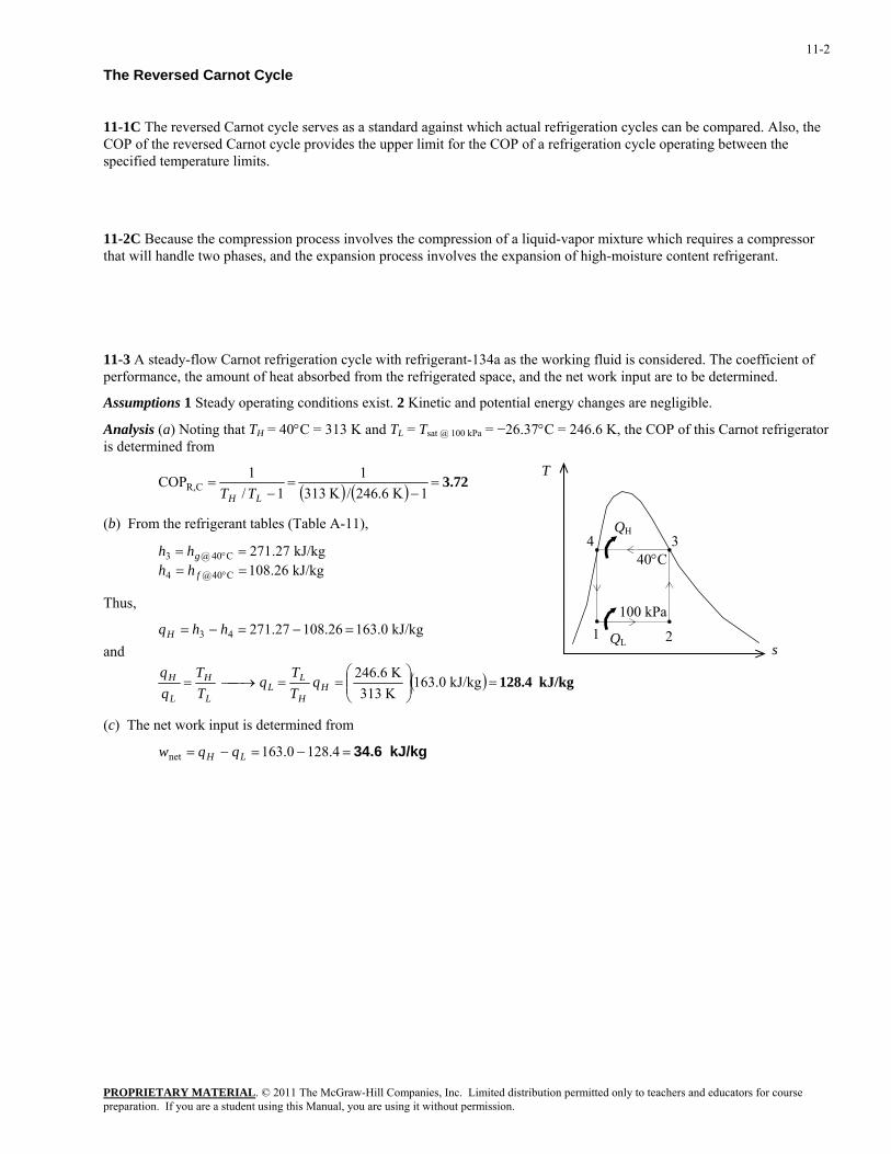
11-3 A steady-flow Carnot refrigeration cycle with refrigerant-134a as the working fluid is considered. The coefficient of performance, the amount of heat absorbed from the refrigerated space, and the net work input are to be determined.
Assumptions 1 Steady operating conditions exist. 2 Kinetic and potential energy changes are negligible.
Analysis (a) Noting that TH = 40°C = 313 K and TL = Tsat @ 100 kPa = −26.37°C = 246.6 K, the COP of this Carnot refrigerator is determined from
T( ) ( ) 3.72=
−=
−=
1K 6.246/K 3131
1/1COP CR,
LH TT
PROPRIETARY MATERIAL. © 2011 The McGraw-Hill Companies, Inc. Limited distribution permitted only to teachers and educators for course
(b) From the refrigerant tables (Table A-11),
kJ/kg 26.108kJ/kg 27.271
C40@4
C40@3====
°
°
f
ghhhh
Thus,
and
( ) kJ/kg 128.4=⎟⎟⎠
⎞⎜⎜⎝
⎛==⎯→⎯=
=−=−=
kJ/kg 163.0K 313K 246.6
kJ/kg 0.16326.10827.27143
HH
LL
L
H
L
H
H
qTT
qTT
hhq
QH
QL
40°C 4 3
2 1100 kPa
s
(c) The net work input is determined from
kJ/kg 34.6=−=−= 4.1280.163net LH qqw
preparation. If you are a student using this Manual, you are using it without permission.
11-3
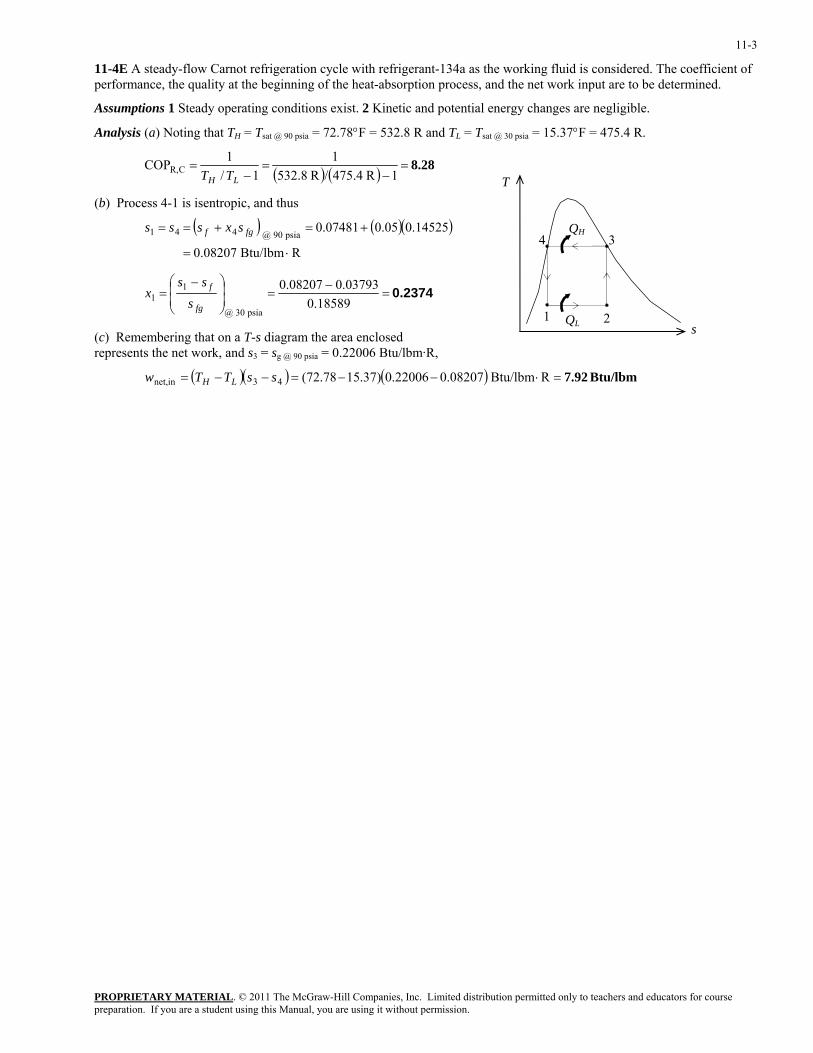
11-4E A steady-flow Carnot refrigeration cycle with refrigerant-134a as the working fluid is considered. The coefficient of performance, the quality at the beginning of the heat-absorption process, and the net work input are to be determined.
Assumptions 1 Steady operating conditions exist. 2 Kinetic and potential energy changes are negligible.
Analysis (a) Noting that TH = Tsat @ 90 psia = 72.78°F = 532.8 R and TL = Tsat @ 30 psia = 15.37°F = 475.4 R.
( ) ( ) 8.28=−
=−
=1R 475.4/R 532.8
11/
1COP CR,LH TT
T
QH
QL
4 3
2 1
(b) Process 4-1 is isentropic, and thus
( ) ( )( )
0.2374=−
=⎟⎟⎠
⎞⎜⎜⎝
⎛ −=
⋅=
+=+==
18589.003793.008207.0
RBtu/lbm 0.08207
14525.005.007481.0
psia 30 @
11
psia 90 @ 441
fg
f
fgf
sss
x
sxsss
s (c) Remembering that on a T-s diagram the area enclosed represents the net work, and s3 = sg @ 90 psia = 0.22006 Btu/lbm·R,
( )( ) ( ) Btu/lbm7.92 RBtu/lbm 08207.022006.0)37.1578.72(43innet, =⋅−−=−−= ssTTw LH
PROPRIETARY MATERIALpreparation. If you are a student using this Manual, you are using it without permission.
. © 2011 The McGraw-Hill Companies, Inc. Limited distribution permitted only to teachers and educators for course
11-4
Ideal and Actual Vapor-Compression Refrigeration Cycles
11-5C Yes; the throttling process is an internally irreversible process.
11-6C To make the ideal vapor-compression refrigeration cycle more closely approximate the actual cycle.
11-7C No. Assuming the water is maintained at 10°C in the evaporator, the evaporator pressure will be the saturation pressure corresponding to this pressure, which is 1.2 kPa. It is not practical to design refrigeration or air-conditioning devices that involve such extremely low pressures.
11-8C Allowing a temperature difference of 10°C for effective heat transfer, the condensation temperature of the refrigerant should be 25°C. The saturation pressure corresponding to 25°C is 0.67 MPa. Therefore, the recommended pressure would be 0.7 MPa.
11-9C The area enclosed by the cyclic curve on a T-s diagram represents the net work input for the reversed Carnot cycle, but not so for the ideal vapor-compression refrigeration cycle. This is because the latter cycle involves an irreversible process for which the process path is not known.
11-10C The cycle that involves saturated liquid at 30°C will have a higher COP because, judging from the T-s diagram, it will require a smaller work input for the same refrigeration capacity.
11-11C The minimum temperature that the refrigerant can be cooled to before throttling is the temperature of the sink (the cooling medium) since heat is transferred from the refrigerant to the cooling medium.
PROPRIETARY MATERIALpreparation. If you are a student using this Manual, you are using it without permission.
. © 2011 The McGraw-Hill Companies, Inc. Limited distribution permitted only to teachers and educators for course
11-5
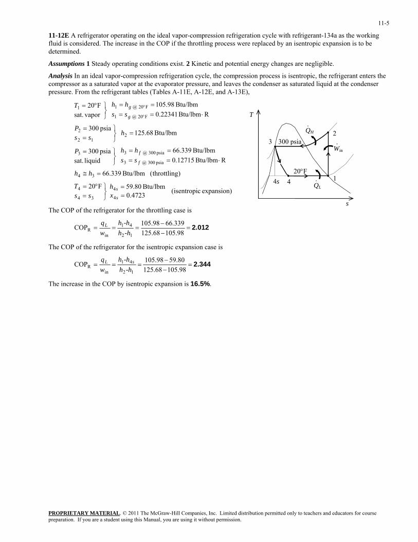
11-12E A refrigerator operating on the ideal vapor-compression refrigeration cycle with refrigerant-134a as the working fluid is considered. The increase in the COP if the throttling process were replaced by an isentropic expansion is to be determined.
Assumptions 1 Steady operating conditions exist. 2 Kinetic and potential energy changes are negligible.
Analysis In an ideal vapor-compression refrigeration cycle, the compression process is isentropic, the refrigerant enters the compressor as a saturated vapor at the evaporator pressure, and leaves the condenser as saturated liquid at the condenser pressure. From the refrigerant tables (Tables A-11E, A-12E, and A-13E),
expansion) c(isentropi 4723.0Btu/lbm 80.59
F20
)throttling( Btu/lbm 339.66
RBtu/lbm 12715.0Btu/lbm 339.66
liquid sat.psia 300
Btu/lbm 68.125 psia 300
RBtu/lbm 22341.0Btu/lbm 98.105
vapor sat.
F20
4
4
34
4
34
psia 300 @ 3
psia 300 @ 33
212
2
F20 @ 1
F20 @ 11
==
⎭⎬⎫
=°=
=≅
⋅====
⎭⎬⎫=
=⎭⎬⎫
==
⋅====
⎭⎬⎫°=
°
°
s
s
f
f
g
g
xh
ssT
hh
sshhP
hss
P
sshhT
QH
QL
20°F 1
23
4
300 psia
·
Win·
·4s
s
T
The COP of the refrigerator for the throttling case is
2.012=−−
===98.10568.125
339.6698.105COP12
41
inR -hh
-hhwqL
The COP of the refrigerator for the isentropic expansion case is
2.344=−−
===98.10568.12580.5998.105COP
12
41
inR -hh
-hhwq sL
The increase in the COP by isentropic expansion is 16.5%.
PROPRIETARY MATERIALpreparation. If you are a student using this Manual, you are using it without permission.
. © 2011 The McGraw-Hill Companies, Inc. Limited distribution permitted only to teachers and educators for course
11-6
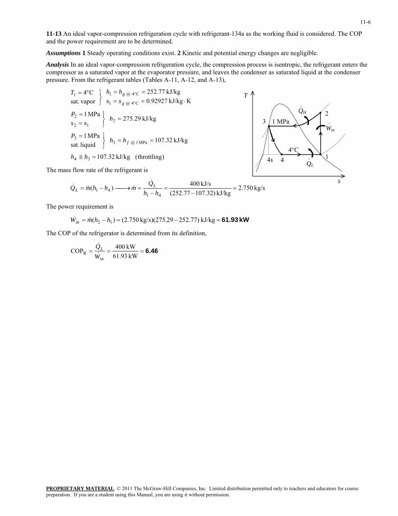
11-13 An ideal vapor-compression refrigeration cycle with refrigerant-134a as the working fluid is considered. The COP and the power requirement are to be determined.
Assumptions 1 Steady operating conditions exist. 2 Kinetic and potential energy changes are negligible.
Analysis In an ideal vapor-compression refrigeration cycle, the compression process is isentropic, the refrigerant enters the compressor as a saturated vapor at the evaporator pressure, and leaves the condenser as saturated liquid at the condenser pressure. From the refrigerant tables (Tables A-11, A-12, and A-13),
)throttling( kJ/kg 32.107
kJ/kg 32.107 liquid sat.
MPa 1
kJ/kg 29.275 MPa 1
KkJ/kg 92927.0kJ/kg 77.252
vapor sat.
C4
34
MPa 1 @ 33
212
2
C4 @ 1
C4 @ 11
=≅
==⎭⎬⎫=
=⎭⎬⎫
==
⋅====
⎭⎬⎫°=
°
°
hh
hhP
hss
P
sshhT
f
g
g
PROPRIETARY MATERIAL. © 2011 The McGraw-Hill Companies, Inc. Limited distribution permitted only to teachers and educators for course
The mass flow rate of the refrigerant is
kg/s 750.2kJ/kg 107.32)(252.77
kJ/s 400)(41
41 =−
=−
=⎯→⎯−=hh
QmhhmQ L
L
&&&&
QH
QL
4°C 1
23
4
1 MPa
·
Win·
·4s
s
T
The power requirement is
kW 61.93=−=−= kJ/kg 252.77)29kg/s)(275. 750.2()( 12in hhmW &&
The COP of the refrigerator is determined from its definition,
6.46===kW 61.93
kW 400COPin
R WQL&
&
preparation. If you are a student using this Manual, you are using it without permission.

11-7
11-14 An ideal vapor-compression refrigeration cycle with refrigerant-134a as the working fluid is considered. The rate of heat removal from the refrigerated space, the power input to the compressor, the rate of heat rejection to the environment, and the COP are to be determined.
Assumptions 1 Steady operating conditions exist. 2 Kinetic and potential energy changes are negligible.
Analysis (a) In an ideal vapor-compression refrigeration cycle, the compression process is isentropic, the refrigerant enters the compressor as a saturated vapor at the evaporator pressure, and leaves the condenser as saturated liquid at the condenser pressure. From the refrigerant tables (Tables A-12 and A-13),
( )
( )throttlingkJ/kg 82.88
kJ/kg 82.88liquid sat.
MPa 7.0
C95.34kJ/kg 50.273MPa 7.0
KkJ/kg 94779.0kJ/kg 97.236
vaporsat.kPa 120
34
MPa 7.0 @ 33
2212
2
kPa 120 @ 1
kPa 120 @ 11
=≅
==⎭⎬⎫=
°==⎭⎬⎫
==
⋅====
⎭⎬⎫=
hh
hhP
Thss
P
sshhP
f
g
g
T
QH
QL
0.121
23
4
0.7 MPa
·
Win·
·4s Then the rate of heat removal from the refrigerated space and the power input to the compressor are determined from s
and ( ) ( )( )
( ) ( )( ) kW 1.83
kW 7.41
=−=−=
=−=−=
kJ/kg 236.97273.50kg/s 0.05
kJ/kg 82.8897.236kg/s 0.05
12in
41
hhmW
hhmQL
&&
&&
(b) The rate of heat rejection to the environment is determined from
kW 9.23=+=+= 83.141.7inWQQ LH&&&
(c) The COP of the refrigerator is determined from its definition,
4.06===kW 1.83kW 7.41COP
inR W
QL&
&
PROPRIETARY MATERIALpreparation. If you are a student using this Manual, you are using it without permission.
. © 2011 The McGraw-Hill Companies, Inc. Limited distribution permitted only to teachers and educators for course
11-8
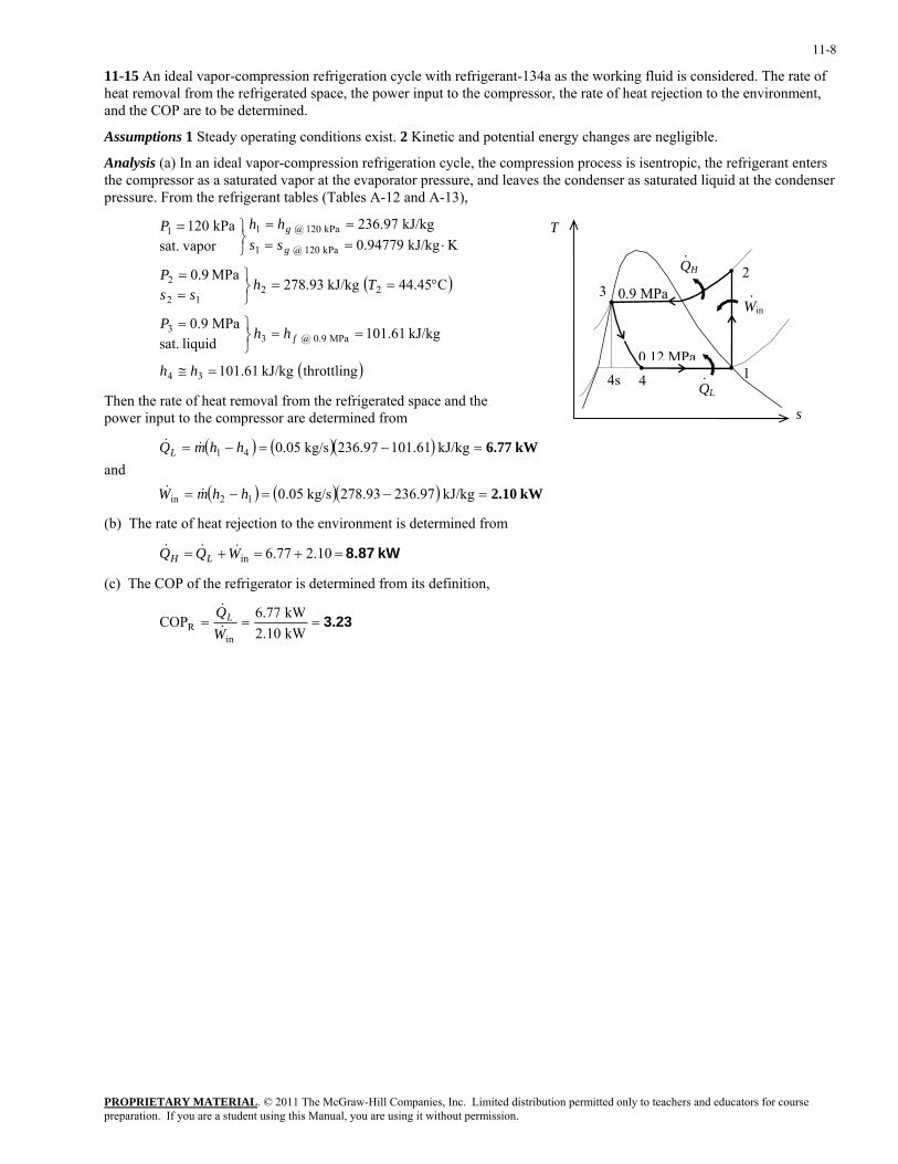
11-15 An ideal vapor-compression refrigeration cycle with refrigerant-134a as the working fluid is considered. The rate of heat removal from the refrigerated space, the power input to the compressor, the rate of heat rejection to the environment, and the COP are to be determined.
Assumptions 1 Steady operating conditions exist. 2 Kinetic and potential energy changes are negligible.
Analysis (a) In an ideal vapor-compression refrigeration cycle, the compression process is isentropic, the refrigerant enters the compressor as a saturated vapor at the evaporator pressure, and leaves the condenser as saturated liquid at the condenser pressure. From the refrigerant tables (Tables A-12 and A-13),
( )
( )throttlingkJ/kg 61.101
kJ/kg 61.101liquid sat.
MPa 9.0
C45.44kJ/kg 93.278MPa 9.0
KkJ/kg 94779.0kJ/kg 97.236
vaporsat.kPa 120
34
MPa 9.0 @ 33
2212
2
kPa 120 @ 1
kPa 120 @ 11
=≅
==⎭⎬⎫=
°==⎭⎬⎫
==
⋅====
⎭⎬⎫=
hh
hhP
Thss
P
sshhP
f
g
g
T
QH
QL
0.12 MPa1
23
4
0.9 MPa
·
Win·
·4sThen the rate of heat removal from the refrigerated space and the power input to the compressor are determined from s
and ( ) ( )( )
( ) ( )( ) kW2.10
kW 6.77
kJ/kg 236.97278.93kg/s 0.05
kJ/kg 61.10197.236kg/s 0.05
12in
41
=−=−=
=−=−=
hhmW
hhmQL
&&
&&
(b) The rate of heat rejection to the environment is determined from
kW 8.87=+=+= 10.277.6inWQQ LH&&&
(c) The COP of the refrigerator is determined from its definition,
3.23===kW 2.10kW 6.77COP
inR W
QL&
&
PROPRIETARY MATERIALpreparation. If you are a student using this Manual, you are using it without permission.
. © 2011 The McGraw-Hill Companies, Inc. Limited distribution permitted only to teachers and educators for course
11-9
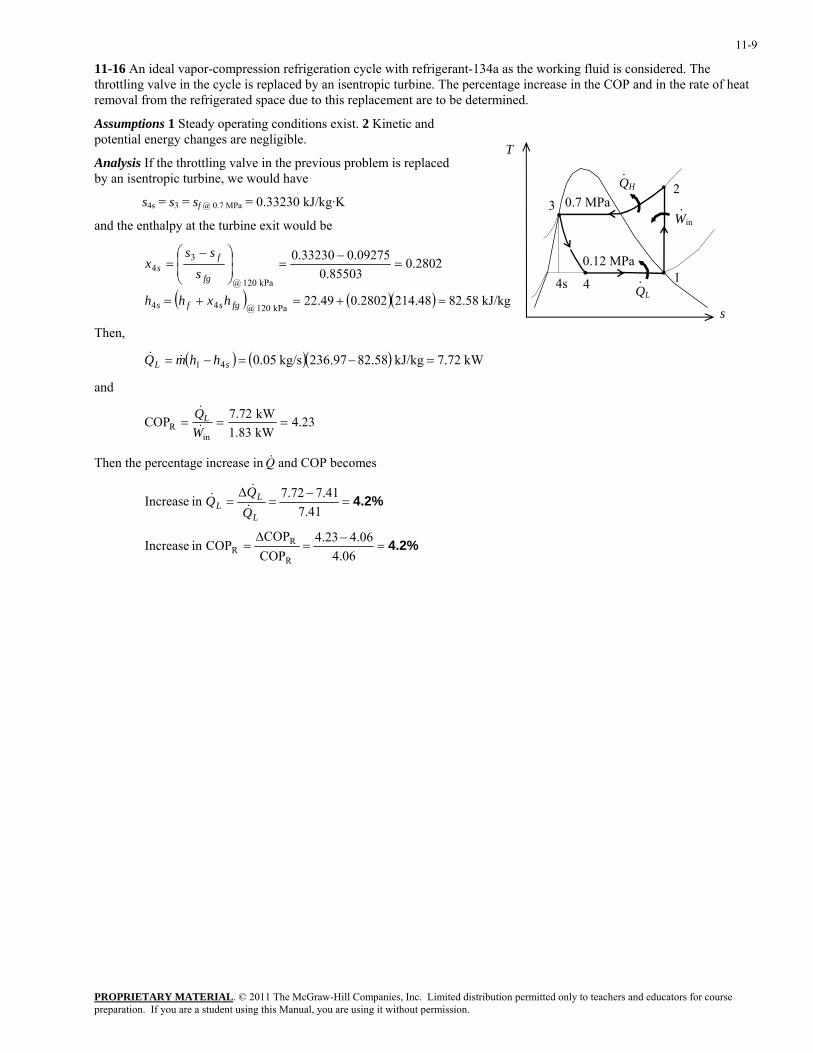
11-16 An ideal vapor-compression refrigeration cycle with refrigerant-134a as the working fluid is considered. The throttling valve in the cycle is replaced by an isentropic turbine. The percentage increase in the COP and in the rate of heat removal from the refrigerated space due to this replacement are to be determined.
Assumptions 1 Steady operating conditions exist. 2 Kinetic and potential energy changes are negligible.
T
QH
QL
0.12 MPa 1
23
4
0.7 MPa
·
Win·
·4s
Analysis If the throttling valve in the previous problem is replaced by an isentropic turbine, we would have
s4s = s3 = sf @ 0.7 MPa = 0.33230 kJ/kg·K
and the enthalpy at the turbine exit would be
( ) ( )( ) kJ/kg 58.8248.2142802.049.22
2802.085503.0
09275.033230.0
kPa 120 @44
kPa 120 @
34
=+=+=
=−
=⎟⎟⎠
⎞⎜⎜⎝
⎛ −=
fgsfs
fg
fs
hxhh
sss
x
s Then,
( ) ( )( ) kW 7.72kJ/kg 82.58236.97kg/s 0.0541 =−=−= sL hhmQ &&
and
23.4kW 1.83kW 7.72COP
inR ===
WQL&
&
Then the percentage increase in and COP becomes &Q
4.2%
4.2%
=−
=∆
=
=−
=∆
=
06.406.423.4
COPCOP
COPin Increase
41.741.772.7in Increase
R
RR
L
LL Q
&
&&
PROPRIETARY MATERIALpreparation. If you are a student using this Manual, you are using it without permission.
. © 2011 The McGraw-Hill Companies, Inc. Limited distribution permitted only to teachers and educators for course
11-10
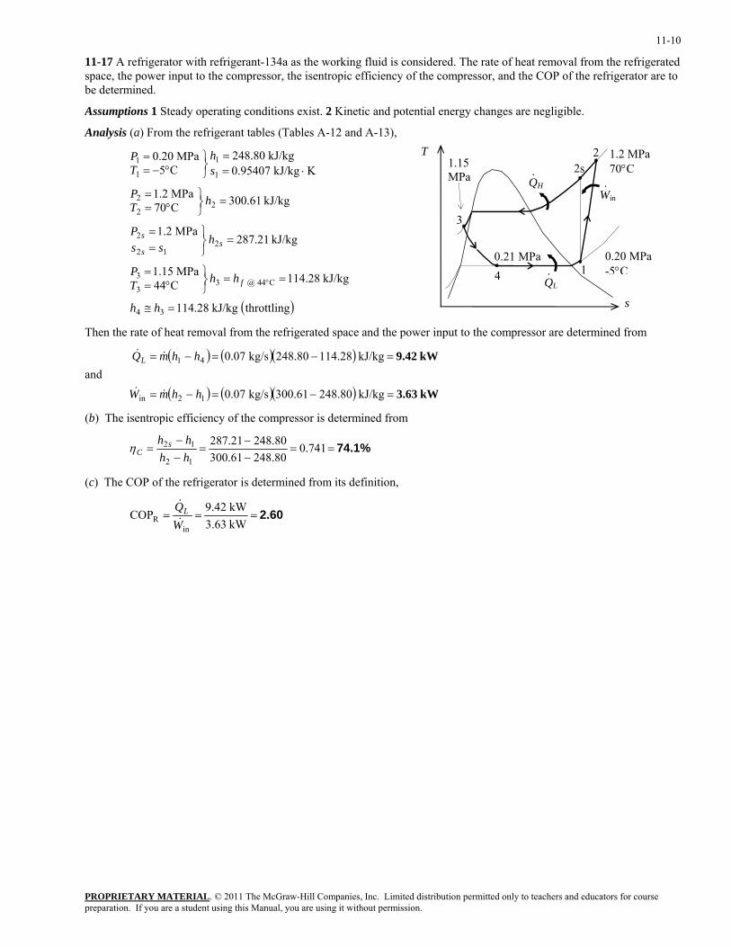
11-17 A refrigerator with refrigerant-134a as the working fluid is considered. The rate of heat removal from the refrigerated space, the power input to the compressor, the isentropic efficiency of the compressor, and the COP of the refrigerator are to be determined.
Assumptions 1 Steady operating conditions exist. 2 Kinetic and potential energy changes are negligible.
Analysis (a) From the refrigerant tables (Tables A-12 and A-13), T
QH
QL
0.21 MPa 1
2s
3
4
1.15 MPa
s
·
·
2
Win·
0.20 MPa-5°C
1.2 MPa 70°C
( )throttlingkJ/kg 28.114
kJ/kg 28.114C44MPa 15.1
kJ/kg 21.287MPa 2.1
kJ/kg 61.300C70MPa 2.1
KkJ/kg 95407.0kJ/kg 80.248
C5MPa 20.0
34
C44 @ 33
3
212
2
22
2
1
1
1
1
=≅
==⎭⎬⎫
°==
=⎭⎬⎫
==
=⎭⎬⎫
°==
⋅==
⎭⎬⎫
°−==
°
hh
hhTP
hss
P
hTP
sh
TP
f
ss
s
Then the rate of heat removal from the refrigerated space and the power input to the compressor are determined from
and ( ) ( )( )
( ) ( )( ) kW 3.63
kW9.42
=−=−=
=−=−=
kJ/kg 248.80300.61kg/s 0.07
kJ/kg 4.2811248.80kg/s 0.07
12in
41
hhmW
hhmQL
&&
&&
(b) The isentropic efficiency of the compressor is determined from
74.1%==−−
=−−
= 741.080.24861.30080.24821.287
12
12
hhhh s
Cη
(c) The COP of the refrigerator is determined from its definition,
2.60===kW 3.63kW 9.42COP
inR W
QL&
&
PROPRIETARY MATERIALpreparation. If you are a student using this Manual, you are using it without permission.
. © 2011 The McGraw-Hill Companies, Inc. Limited distribution permitted only to teachers and educators for course
11-11
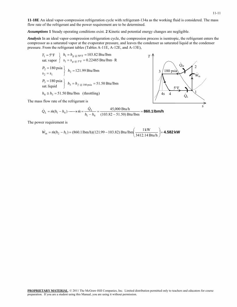
11-18E An ideal vapor-compression refrigeration cycle with refrigerant-134a as the working fluid is considered. The mass flow rate of the refrigerant and the power requirement are to be determined.
Assumptions 1 Steady operating conditions exist. 2 Kinetic and potential energy changes are negligible.
Analysis In an ideal vapor-compression refrigeration cycle, the compression process is isentropic, the refrigerant enters the compressor as a saturated vapor at the evaporator pressure, and leaves the condenser as saturated liquid at the condenser pressure. From the refrigerant tables (Tables A-11E, A-12E, and A-13E),
)throttling( Btu/lbm 50.51
Btu/lbm 50.51 liquid sat.psia 180
Btu/lbm 99.121 psia 180
RBtu/lbm 22485.0Btu/lbm 82.103
vapor sat.
F5
34
psia 180 @ 33
212
2
F5 @ 1
F05 @ 11
=≅
==⎭⎬⎫=
=⎭⎬⎫
==
⋅====
⎭⎬⎫°=
°
°
hh
hhP
hss
P
sshhT
f
g
g
PROPRIETARY MATERIAL. © 2011 The McGraw-Hill Companies, Inc. Limited distribution permitted only to teachers and educators for course
The mass flow rate of the refrigerant is
lbm/h 860.1=−
=−
=⎯→⎯−=Btu/lbm )50.51(103.82
Btu/h 000,45)(41
41 hhQ
mhhmQ LL
&&&&
QH
QL
5°F 1
23
4
180 psia
·
Win·
·
4s
s
T
The power requirement is
kW 4.582=⎟⎠⎞
⎜⎝⎛−=−=
Btu/h 3412.14kW 1Btu/lbm )82.103.99lbm/h)(121 1.860()( 12in hhmW &&
preparation. If you are a student using this Manual, you are using it without permission.
11-12
11-19E Problem 11-18E is to be repeated if ammonia is used as the refrigerant.
Analysis The problem is solved using EES, and the solution is given below.
"Given" x[1]=1 T[1]=5 [F] x[3]=0 P[3]=180 [psia] Q_dot_L=45000 [Btu/h] "Analysis" Fluid$='ammonia' "compressor" h[1]=enthalpy(Fluid$, T=T[1], x=x[1]) s[1]=entropy(Fluid$, T=T[1], x=x[1]) s[2]=s[1] P[2]=P[3] h[2]=enthalpy(Fluid$, P=P[2], s=s[2]) "expansion valve" h[3]=enthalpy(Fluid$, P=P[3], x=x[3]) h[4]=h[3] "cycle" m_dot_R=Q_dot_L/(h[1]-h[4]) W_dot_in=m_dot_R*(h[2]-h[1])*Convert(Btu/h, kW) Solution for ammonia COP_R=4.515 Fluid$='ammonia' m_dot_R=95.8 [lbm/h] Q_dot_L=45000 [Btu/h] W_dot_in=2.921 [kW] Solution for R-134a COP_R=2.878 Fluid$='R134a' m_dot_R=860.1 [lbm/h] Q_dot_L=45000 [Btu/h] W_dot_in=4.582 [kW]
PROPRIETARY MATERIALpreparation. If you are a student using this Manual, you are using it without permission.
. © 2011 The McGraw-Hill Companies, Inc. Limited distribution permitted only to teachers and educators for course
11-13
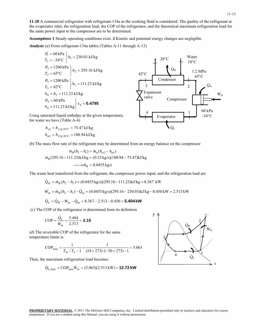
11-20 A commercial refrigerator with refrigerant-134a as the working fluid is considered. The quality of the refrigerant at the evaporator inlet, the refrigeration load, the COP of the refrigerator, and the theoretical maximum refrigeration load for the same power input to the compressor are to be determined.
Assumptions 1 Steady operating conditions exist. 2 Kinetic and potential energy changes are negligible.
Analysis (a) From refrigerant-134a tables (Tables A-11 through A-13)
0.4795=⎭⎬⎫
==
==
=⎭⎬⎫
°==
=⎭⎬⎫
°==
=⎭⎬⎫
°−==
44
4
34
33
3
22
2
11
1
kJ/kg 23.111kPa 60
kJ/kg 23.111
kJ/kg 23.111C42
kPa 1200
kJ/kg 16.295C65
kPa 1200
kJ/kg 03.230C34
kPa 60
xhP
hh
hTP
hTP
hTP
60 kPa -34°C
1
2 3
4
QH42°C
Win
Condenser
Evaporator
Compressor
Expansion valve
QL
1.2 MPa 65°C
Qin
26°C Water 18°C
Using saturated liquid enthalpy at the given temperature, for water we have (Table A-4)
kJ/kg 94.108
kJ/kg 47.75
C26 @2
C18 @1
==
==
°
°
fw
fw
hh
hh
(b) The mass flow rate of the refrigerant may be determined from an energy balance on the compressor
kg/s 0455.0
g75.47)kJ/k94kg/s)(108. (0.25kJ/kg)23.11116.295()()( 1232
=⎯→⎯
−=−−=−
R
R
wwwR
m
mhhmhhm
&
&
&&
The waste heat transferred from the refrigerant, the compressor power input, and the refrigeration load are
kW 367.8kJ/kg)23.11116kg/s)(295. 0455.0()( 32 =−=−= hhmQ RH &&
kW 513.2kW 0.450kJ/kg)03.23016kg/s)(295. 0455.0()( in12in =−−=−−= QhhmW R&&&
kW 5.404=−−=−−= 450.0513.2367.8inin QWQQ HL&&&&
(c) The COP of the refrigerator is determined from its definition T
QH
QL
1
2
3
4
·
·
2
Win·
2.15===513.2404.5COP
in
L
WQ&
&
(d) The reversible COP of the refrigerator for the same temperature limits is
063.51)27330/()27318(
11/
1COPmax =−+−+
=−
=LH TT
Then, the maximum refrigeration load becomes s
kW 12.72=== kW) 513.2)(063.5(inmaxmaxL, WCOPQ &&
PROPRIETARY MATERIALpreparation. If you are a student using this Manual, you are using it without permission.
. © 2011 The McGraw-Hill Companies, Inc. Limited distribution permitted only to teachers and educators for course
11-14
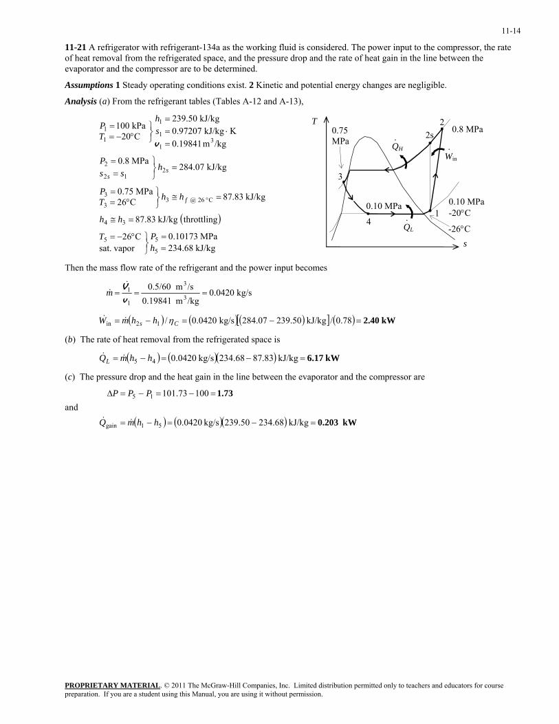
11-21 A refrigerator with refrigerant-134a as the working fluid is considered. The power input to the compressor, the rate of heat removal from the refrigerated space, and the pressure drop and the rate of heat gain in the line between the evaporator and the compressor are to be determined.
Assumptions 1 Steady operating conditions exist. 2 Kinetic and potential energy changes are negligible.
Analysis (a) From the refrigerant tables (Tables A-12 and A-13),
( )
kJ/kg 68.234MPa 10173.0
vapor sat.C26
throttlingkJ/kg 83.87
kJ/kg 83.87C26MPa 75.0
kJ/kg 07.284MPa 8.0
/kgm 19841.0KkJ/kg 97207.0
kJ/kg 50.239
C20kPa 100
5
55
34
C 26 @ 33
3
212
2
31
1
1
1
1
==
⎭⎬⎫°−=
=≅
=≅⎭⎬⎫
°==
=⎭⎬⎫
==
=⋅=
=
⎭⎬⎫
°−==
°
hPT
hh
hhTP
hss
P
sh
TP
f
ss
v
T
QH
QL
0.10 MPa
1
2s
3
4
0.75 MPa
s
0.8 MPa
·
·
2
Win·
0.10 M-20°C
-26°C
Pa
Then the mass flow rate of the refrigerant and the power input becomes
( ) ( ) ( )[ ] ( ) kW2.40 78.0/kJ/kg 239.50284.07kg/s 0.0420/
kg/s 0.0420/kgm 0.19841/sm 0.5/60
12in
3
3
1
1
=−=−=
===
Cs hhmW
m
η&&
&&
v
V
(b) The rate of heat removal from the refrigerated space is
( ) ( )( ) kW 6.17=−=−= kJ/kg .8387234.68kg/s 0.042045 hhmQL &&
(c) The pressure drop and the heat gain in the line between the evaporator and the compressor are
and
( ) ( )( ) kW0.203
1.73
kJ/kg 234.68239.50kg/s 0.0420
10073.101
51gain
15
=−=−=
=−=−=∆
hhmQ
PPP
&&
PROPRIETARY MATERIALpreparation. If you are a student using this Manual, you are using it without permission.
. © 2011 The McGraw-Hill Companies, Inc. Limited distribution permitted only to teachers and educators for course
11-15
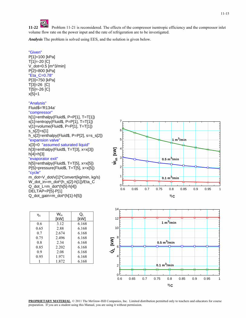
11-22 Problem 11-21 is reconsidered. The effects of the compressor isentropic efficiency and the compressor inlet volume flow rate on the power input and the rate of refrigeration are to be investigated.
Analysis The problem is solved using EES, and the solution is given below.
"Given" P[1]=100 [kPa] T[1]=-20 [C] V_dot=0.5 [m^3/min] P[2]=800 [kPa] "Eta_C=0.78" P[3]=750 [kPa] T[3]=26 [C] T[5]=-26 [C] x[5]=1 "Analysis" Fluid$='R134a' "compressor" h[1]=enthalpy(Fluid$, P=P[1], T=T[1]) s[1]=entropy(Fluid$, P=P[1], T=T[1])
0.6 0.65 0.7 0.75 0.8 0.85 0.9 0.95 10
1
2
3
4
5
6
7
ηC
Win
[kW
]
0.1 m3/min
0.5 m3/min
1 m3/min
v[1]=volume(Fluid$, P=P[1], T=T[1]) s_s[2]=s[1] h_s[2]=enthalpy(Fluid$, P=P[2], s=s_s[2]) "expansion valve" x[3]=0 "assumed saturated liquid" h[3]=enthalpy(Fluid$, T=T[3], x=x[3]) h[4]=h[3] "evaporator exit" h[5]=enthalpy(Fluid$, T=T[5], x=x[5]) P[5]=pressure(Fluid$, T=T[5], x=x[5]) "cycle" m_dot=V_dot/v[1]*Convert(kg/min, kg/s) W_dot_in=m_dot*(h_s[2]-h[1])/Eta_C Q_dot_L=m_dot*(h[5]-h[4]) DELTAP=P[5]-P[1] Q_dot_gain=m_dot*(h[1]-h[5])
0.6 0.65 0.7 0.75 0.8 0.85 0.9 0.95 10
2
4
6
8
10
12
14
ηC
QL
[kW
]
0.5 m3/min
1 m3/min
0.1 m3/min
ηc Win [kW]
QL [kW]
0.6 0.65 0.7
0.75 0.8
0.85 0.9
0.95 1
3.12 2.88
2.674 2.496 2.34
2.202 2.08
1.971 1.872
6.168 6.168 6.168 6.168 6.168 6.168 6.168 6.168 6.168
PROPRIETARY MATERIALpreparation. If you are a student using this Manual, you are using it without permission.
. © 2011 The McGraw-Hill Companies, Inc. Limited distribution permitted only to teachers and educators for course
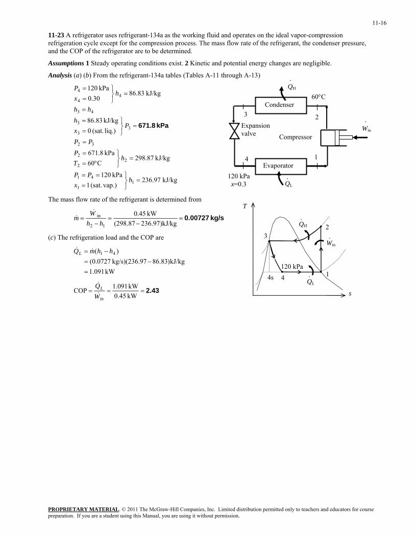
11-16
11-23 A refrigerator uses refrigerant-134a as the working fluid and operates on the ideal vapor-compression refrigeration cycle except for the compression process. The mass flow rate of the refrigerant, the condenser pressure, and the COP of the refrigerator are to be determined.
Assumptions 1 Steady operating conditions exist. 2 Kinetic and potential energy changes are negligible.
Analysis (a) (b) From the refrigerant-134a tables (Tables A-11 through A-13)
.
QH
.
60°C
Win
.
Condenser
Evaporator
Compressor
Expansion valve
1
2 3
4
QL
120 kPa x=0.3 kJ/kg 97.236
vap.)(sat. 1kPa 120
kJ/kg 87.298C60
kPa 8.671
liq.) (sat. 0kJ/kg 83.86
kJ/kg 83.8630.0
kPa 120
11
41
22
2
32
33
3
43
44
4
=⎭⎬⎫
===
=⎭⎬⎫
°==
=
=⎭⎬⎫
==
=
=⎭⎬⎫
==
hx
PP
hTP
PP
Pxh
hh
hxP
kPa 671.8
The mass flow rate of the refrigerant is determined from T
QH
QL
120 kPa1
2 3
4
·
Win·
·4s
kg/s 0.00727=−
=−
=kg236.97)kJ/(298.87
kW 45.0
12
in
hhW
m&
&
(c) The refrigeration load and the COP are
kW 091.1kJ/kg)83.8697kg/s)(236. 0727.0(
)( 41
=−=
−= hhmQL &&
2.43===kW 0.45kW 091.1COP
in
L
WQ&
& s
PROPRIETARY MATERIALpreparation. If you are a student using this Manual, you are using it without permission.
. © 2011 The McGraw-Hill Companies, Inc. Limited distribution permitted only to teachers and educators for course
11-17
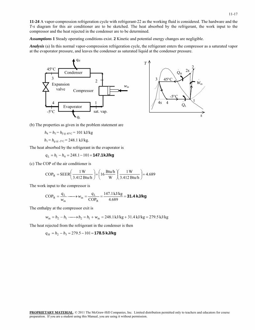
11-24 A vapor-compression refrigeration cycle with refrigerant-22 as the working fluid is considered. The hardware and the T-s diagram for this air conditioner are to be sketched. The heat absorbed by the refrigerant, the work input to the compressor and the heat rejected in the condenser are to be determined.
Assumptions 1 Steady operating conditions exist. 2 Kinetic and potential energy changes are negligible.
Analysis (a) In this normal vapor-compression refrigeration cycle, the refrigerant enters the compressor as a saturated vapor at the evaporator pressure, and leaves the condenser as saturated liquid at the condenser pressure.
1
2 3
4
qH
-5°C
win
Condenser
Evaporator
Compressor Expansion
valve
45°C
qL
sat. vap.
QH
QL
-5°C 1
2
3
4
45°CWin·
·
· 2s
4s
s
T
(b) The properties as given in the problem statement are
h4 = h3 = hf @ 45°C = 101 kJ/kg
h1 = hg @ -5°C = 248.1 kJ/kg.
The heat absorbed by the refrigerant in the evaporator is
kJ/kg 147.1=−=−= 1011.24841 hhqL
(c) The COP of the air conditioner is
689.4Btu/h 3.412
W1W
Btu/h 16Btu/h 3.412
W1SEERCOPR =⎟⎠⎞
⎜⎝⎛
⎟⎠⎞
⎜⎝⎛=⎟
⎠⎞
⎜⎝⎛=
The work input to the compressor is
kJ/kg 31.4===⎯→⎯=689.4kJ/kg 1.147
COPCOP
Rin
inR
LL qw
wq
The enthalpy at the compressor exit is
kJ/kg 5.279kJ/kg 4.31kJ/kg 1.248in1212in =+=+=⎯→⎯−= whhhhw
The heat rejected from the refrigerant in the condenser is then
kJ/kg 178.5=−=−= 1015.27932 hhqH
PROPRIETARY MATERIALpreparation. If you are a student using this Manual, you are using it without permission.
. © 2011 The McGraw-Hill Companies, Inc. Limited distribution permitted only to teachers and educators for course
11-18
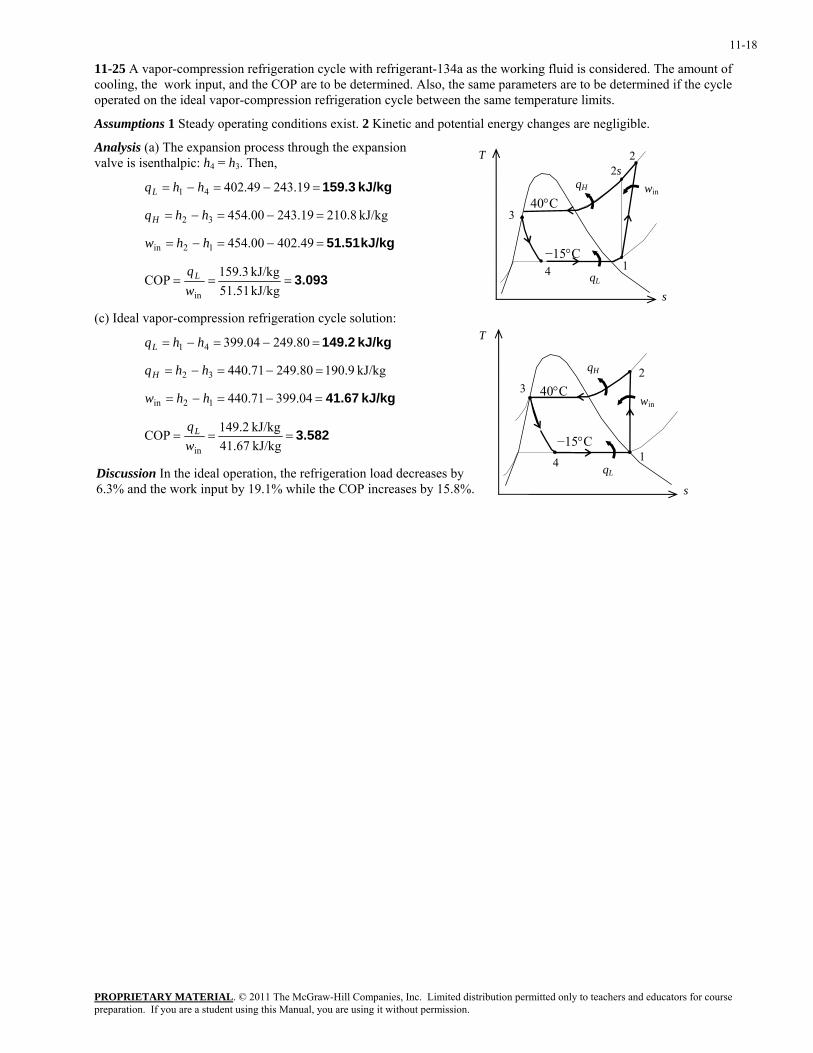
11-25 A vapor-compression refrigeration cycle with refrigerant-134a as the working fluid is considered. The amount of cooling, the work input, and the COP are to be determined. Also, the same parameters are to be determined if the cycle operated on the ideal vapor-compression refrigeration cycle between the same temperature limits.
Assumptions 1 Steady operating conditions exist. 2 Kinetic and potential energy changes are negligible.
Analysis (a) The expansion process through the expansion valve is isenthalpic: h4 = h3. Then, T
qH
qL
1
2s
3
4
2
win
40°C
−15°C
kJ/kg 159.3=−=−= 19.24349.40241 hhqL
kJ/kg 8.21019.24300.45432 =−=−= hhqH
kJ/kg 51.51=−=−= 49.40200.45412in hhw
3.093===kJ/kg 51.51kJ/kg 3.159COP
inwqL
s
(c) Ideal vapor-compression refrigeration cycle solution: T
qH
qL
1
2 3
4
40°C
−15°C
win
kJ/kg 149.2=−=−= 80.24904.39941 hhqL
kJ/kg 190.980.24971.44032 =−=−= hhqH
kJ/kg 41.67=−=−= 04.39971.44012in hhw
3.582===kJ/kg 67.41kJ/kg 2.149COP
inwqL
Discussion In the ideal operation, the refrigeration load decreases by 6.3% and the work input by 19.1% while the COP increases by 15.8%. s
PROPRIETARY MATERIALpreparation. If you are a student using this Manual, you are using it without permission.
. © 2011 The McGraw-Hill Companies, Inc. Limited distribution permitted only to teachers and educators for course
11-19
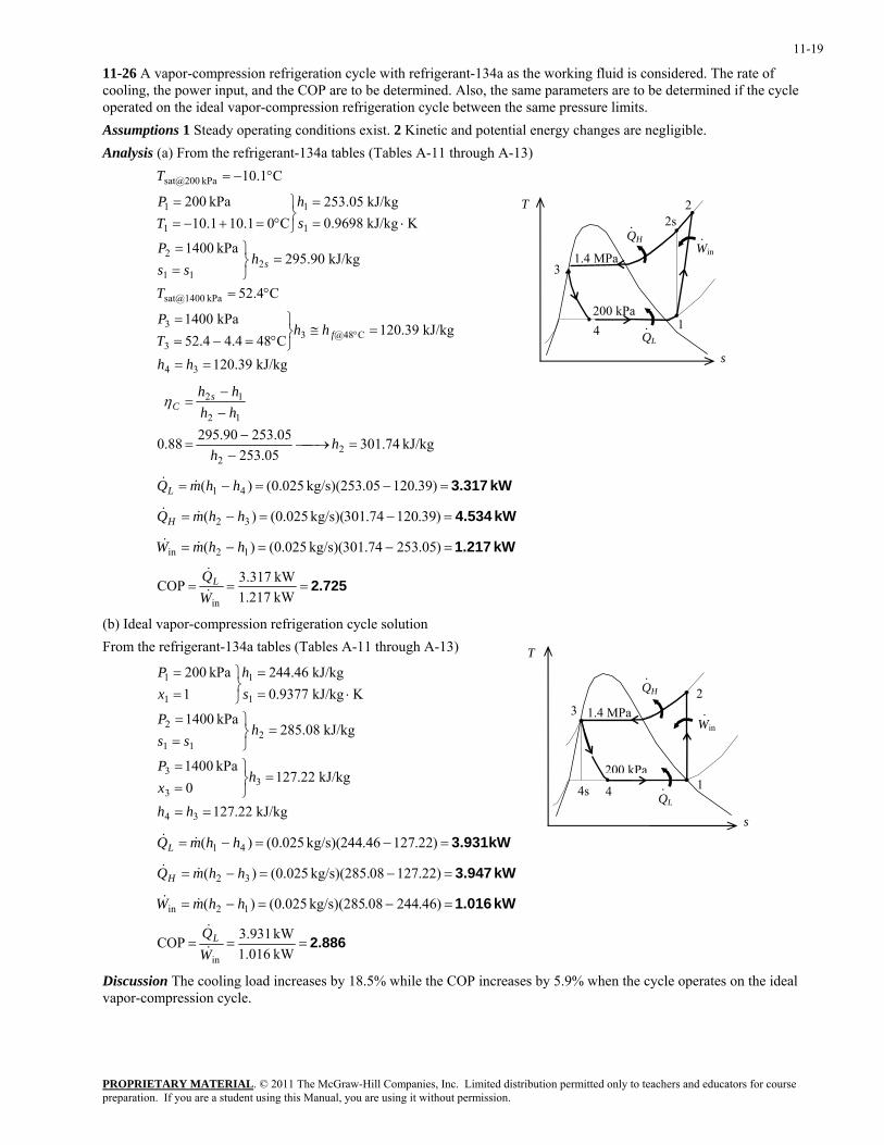
11-26 A vapor-compression refrigeration cycle with refrigerant-134a as the working fluid is considered. The rate of cooling, the power input, and the COP are to be determined. Also, the same parameters are to be determined if the cycle operated on the ideal vapor-compression refrigeration cycle between the same pressure limits. Assumptions 1 Steady operating conditions exist. 2 Kinetic and potential energy changes are negligible. Analysis (a) From the refrigerant-134a tables (Tables A-11 through A-13)
kJ/kg 39.120
kJ/kg 39.120C484.44.52
kPa 1400
C4.52
kJ/kg 90.295kPa 1400
KkJ/kg 9698.0kJ/kg 05.253
C01.101.10kPa 200
C1.10
34
C@4833
3
kPa sat@1400
211
2
1
1
1
1
kPa sat@200
==
=≅⎭⎬⎫
°=−==
°=
=⎭⎬⎫
==
⋅==
⎭⎬⎫
°=+−==
°−=
°
hh
hhTP
T
hss
P
sh
TP
T
f
s
T
QH
QL
200 kPa 1
2s
3
4
1.4 MPa
2
Win·
·
·
s
kJ/kg 74.301
05.25305.25390.29588.0 2
2
12
12
=⎯→⎯−
−=
−−
=
hh
hhhh s
Cη
kW 3.317=−=−= )39.12005.253kg/s)( 025.0()( 41 hhmQL &&
kW 4.534=−=−= )39.12074.301kg/s)( 025.0()( 32 hhmQH &&
kW 1.217=−=−= )05.25374.301kg/s)( 025.0()( 12in hhmW &&
2.725===kW 217.1kW 317.3COP
inWQL&
&
(b) Ideal vapor-compression refrigeration cycle solution From the refrigerant-134a tables (Tables A-11 through A-13) T
QH
QL
200 kPa1
2 3
4
1.4 MPa
·
Win·
·4s
kJ/kg 22.127
kJ/kg 22.1270
kPa 1400
kJ/kg 08.285kPa 1400
KkJ/kg 9377.0kJ/kg 46.244
1kPa 200
34
33
3
211
2
1
1
1
1
==
=⎭⎬⎫
==
=⎭⎬⎫
==
⋅==
⎭⎬⎫
==
hh
hxP
hss
P
sh
xP
s
kW 3.931=−=−= )22.12746.244kg/s)( 025.0()( 41 hhmQL &&
kW 3.947=−=−= )22.12708kg/s)(285. 025.0()( 32 hhmQH &&
kW 1.016=−=−= )46.24408.kg/s)(285 025.0()( 12in hhmW &&
2.886===kW 016.1kW 931.3COP
inWQL&
&
Discussion The cooling load increases by 18.5% while the COP increases by 5.9% when the cycle operates on the ideal vapor-compression cycle.
PROPRIETARY MATERIALpreparation. If you are a student using this Manual, you are using it without permission.
. © 2011 The McGraw-Hill Companies, Inc. Limited distribution permitted only to teachers and educators for course
11-20
Second-Law Analysis of Vapor-Compression Refrigeration Cycles
11-27C The second-law efficiency of a refrigerator operating on the vapor-compression refrigeration cycle is defined as
W
XW
WW
XLQ
&
&
&
&
&
&& totaldest,min
RII, 1 −===η
where is the exergy of the heat transferred from the low-temperature medium and it is expressed as LQX &
&
⎟⎟⎠
⎞⎜⎜⎝
⎛−−=
LLQ T
TQX
L
01&&& .
totaldest,X& is the total exergy destruction in the cycle and W is the actual power input to the cycle. The second-law efficiency can also be expressed as the ratio of the actual COP to the Carnot COP:
&
Carnot
RRII, COP
COP=η
11-28C The second-law efficiency of a heat pump operating on the a vapor-compression refrigeration cycle is defined as
W
xEW
WW
xEHQ
&
&
&
&
&
&& totaldest,min
HPII, 1 −===η
Substituting
HPCOPHQ
W&
& = and ⎟⎟⎠
⎞⎜⎜⎝
⎛−=
HHQ T
TQxEH
01&&&
into the second-law efficiency equation
Carnot
HPHPHP0
HP
0
HPII, COPCOPCOPCOP
1
COP
1=
−
=⎟⎟⎠
⎞⎜⎜⎝
⎛−=
⎟⎟⎠
⎞⎜⎜⎝
⎛−
==
LH
HHHH
H
HH
Q
TTTQT
TQ
Q
TT
Q
W
xEH
&&
&
&
&
&&
η
since T0.= TL.
PROPRIETARY MATERIALpreparation. If you are a student using this Manual, you are using it without permission.
. © 2011 The McGraw-Hill Companies, Inc. Limited distribution permitted only to teachers and educators for course
11-21
11-29C In an isentropic compressor, s2 = s1 and h2s = h2. Applying these to the two the efficiency definitions, we obtain
%100112
12
12
12isenComps, ==
−−
=−−
==hhhh
hhhh
ww sη
%1001)(
12
12
12
12012revCompII, ==
−−
=−
−−−==
hhhh
hhssThh
ww
η
Thus, the isentropic efficiency and the exergy efficiency of an isentropic compressor are both 100%.
The exergy efficiency of a compressor is not necessarily equal to its isentropic efficiency. The two definitions are different as shown in the above equations. In the calculation of isentropic efficiency, the exit enthalpy is found at the hypothetical exit state (at the exit pressure and the inlet entropy) while the exergy efficiency involves the actual exit state. The two efficiencies are usually close but different. In the special case of an isentropic compressor, the two efficiencies become equal to each other as proven above.
11-30 A vapor-compression refrigeration system is used to keep a space at a low temperature. The power input, the COP and the second-law efficiency are to be determined.
Assumptions 1 Steady operating conditions exist. 2 Kinetic and potential energy changes are negligible.
Analysis The power input is
kW 0.6944=⎟⎠⎞
⎜⎝⎛==−=−=
kJ/h 3600kW 1kJ/h) 2500(kJ/h 250035006000in LH QQW &&&
The COP is
1.4===kW 6944.0
kW )3600/3500(COPin
R WQL&
&
The COP of the Carnot cycle operating between the space and the ambient is
208.5K )250298(
K 250COPCarnot =−
=−
=LH
L
TTT
The second-law efficiency is then
26.9%==== 2688.0208.54.1
COPCOP
Carnot
RIIη
PROPRIETARY MATERIALpreparation. If you are a student using this Manual, you are using it without permission.
. © 2011 The McGraw-Hill Companies, Inc. Limited distribution permitted only to teachers and educators for course
11-22
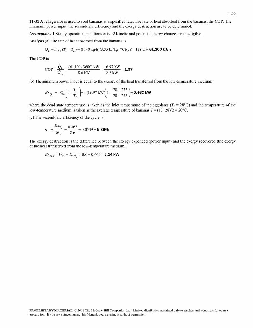
11-31 A refrigerator is used to cool bananas at a specified rate. The rate of heat absorbed from the bananas, the COP, The minimum power input, the second-law efficiency and the exergy destruction are to be determined.
Assumptions 1 Steady operating conditions exist. 2 Kinetic and potential energy changes are negligible.
Analysis (a) The rate of heat absorbed from the bananas is
kJ/h 61,100=°−°⋅=−= C)1228(C)kJ/kg 35.3(kg/h) 1140()( 21 TTcmQ pL &&
The COP is
1.97====kW 6.8kW 97.16
kW 6.8kW )3600/100,61(COP
inWQL&
&
(b) Theminimum power input is equal to the exergy of the heat transferred from the low-temperature medium:
kW 0.463=⎟⎠⎞
⎜⎝⎛
++
−−=⎟⎟⎠
⎞⎜⎜⎝
⎛−−=
27320273281kW) 97.16(1 0
LLQ T
TQxE
L
&&&
where the dead state temperature is taken as the inlet temperature of the eggplants (T0 = 28°C) and the temperature of the low-temperature medium is taken as the average temperature of bananas T = (12+28)/2 = 20°C.
(c) The second-law efficiency of the cycle is
5.39%==== 0.05396.8
463.0
inII W
xELQ
&
&&
η
The exergy destruction is the difference between the exergy expended (power input) and the exergy recovered (the exergy of the heat transferred from the low-temperature medium):
kW 8.14=−=−= 463.06.8indest LQxEWxE &&&&
PROPRIETARY MATERIALpreparation. If you are a student using this Manual, you are using it without permission.
. © 2011 The McGraw-Hill Companies, Inc. Limited distribution permitted only to teachers and educators for course
11-23
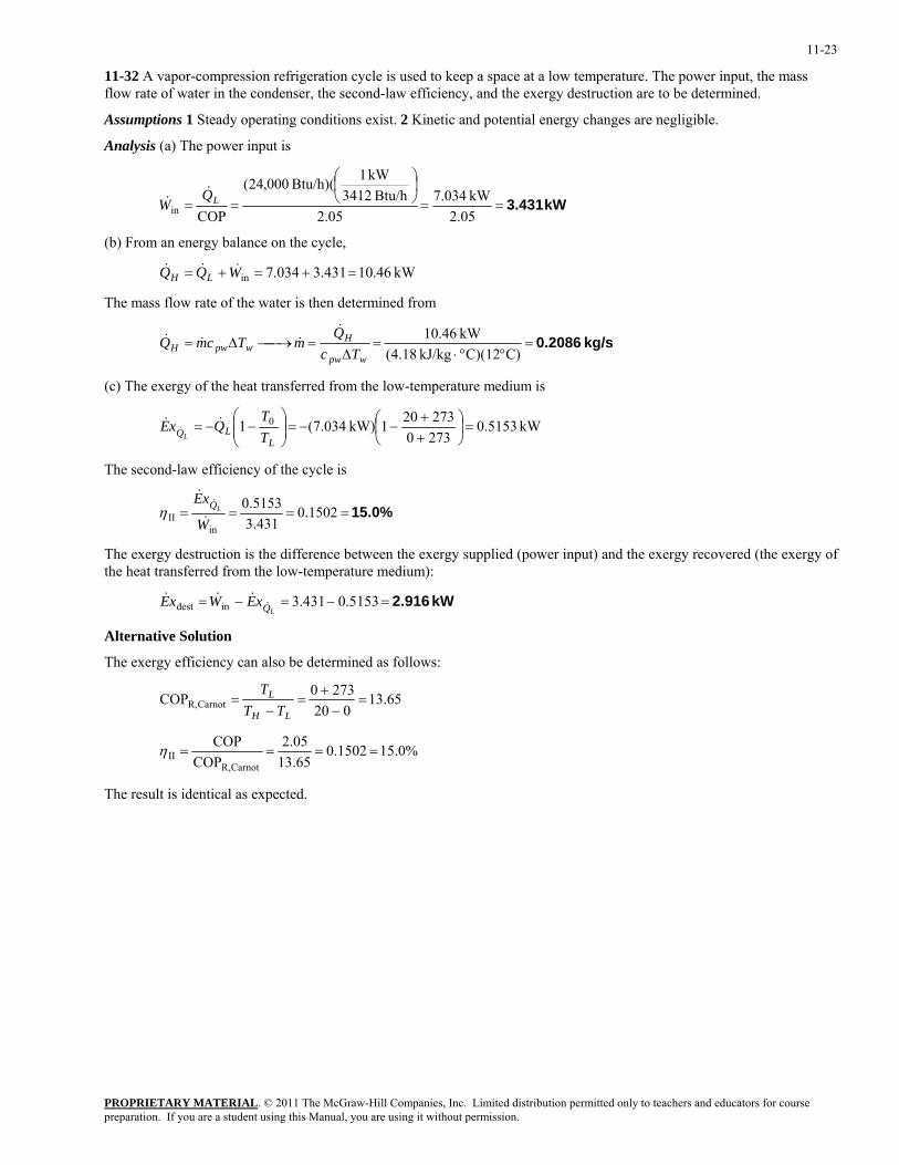
11-32 A vapor-compression refrigeration cycle is used to keep a space at a low temperature. The power input, the mass flow rate of water in the condenser, the second-law efficiency, and the exergy destruction are to be determined.
Assumptions 1 Steady operating conditions exist. 2 Kinetic and potential energy changes are negligible.
Analysis (a) The power input is
kW 3.431==⎟⎠⎞
⎜⎝⎛
==05.2
kW 034.705.2
Btu/h 3412kW 1Btu/h)( 000,24(
COPinLQ
W&
&
(b) From an energy balance on the cycle,
kW 46.10431.3034.7in =+=+= WQQ LH&&&
The mass flow rate of the water is then determined from
kg/s 0.2086=°°⋅
=∆
=⎯→⎯∆=C)C)(12kJ/kg 18.4(
kW 46.10
wpw
HwpwH Tc
QmTcmQ
&&&&
(c) The exergy of the heat transferred from the low-temperature medium is
kW 0.51532730273201kW) 034.7(1 0 =⎟
⎠⎞
⎜⎝⎛
++
−−=⎟⎟⎠
⎞⎜⎜⎝
⎛−−=
LLQ T
TQxE
L
&&&
The second-law efficiency of the cycle is
15.0%==== 0.1502431.3
5153.0
inII W
xELQ
&
&&
η
The exergy destruction is the difference between the exergy supplied (power input) and the exergy recovered (the exergy of the heat transferred from the low-temperature medium):
kW 2.916=−=−= 5153.0431.3indest LQxEWxE &&&&
Alternative Solution
The exergy efficiency can also be determined as follows:
65.13020
2730COP CarnotR, =−
+=
−=
LH
L
TTT
15.0%0.150265.1305.2
COPCOP
CarnotR,II ====η
The result is identical as expected.
PROPRIETARY MATERIALpreparation. If you are a student using this Manual, you are using it without permission.
. © 2011 The McGraw-Hill Companies, Inc. Limited distribution permitted only to teachers and educators for course
11-24
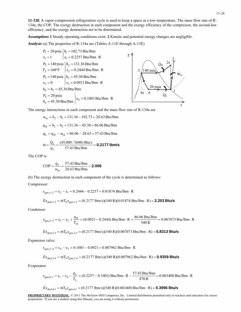
11-33E A vapor-compression refrigeration cycle is used to keep a space at a low temperature. The mass flow rate of R-134a, the COP, The exergy destruction in each component and the exergy efficiency of the compressor, the second-law efficiency, and the exergy destruction are to be determined.
Assumptions 1 Steady operating conditions exist. 2 Kinetic and potential energy changes are negligible.
Analysis (a) The properties of R-134a are (Tables A-11E through A-13E)
RBtu/lbm 1001.0Btu/lbm 30.45
psia 20Btu/lbm 30.45
RBtu/lbm 0921.0Btu/lbm 30.45
0psia 140
RBtu/lbm 2444.0Btu/lbm 36.131
F160psia 140
RBtu/lbm 2257.0Btu/lbm 73.102
1psia 20
44
4
34
3
3
3
3
2
2
2
2
1
1
1
1
⋅=⎭⎬⎫
==
==
⋅==
⎭⎬⎫
==
⋅==
⎭⎬⎫
°==
⋅==
⎭⎬⎫
==
shP
hhsh
xP
sh
TP
sh
xP
PROPRIETARY MATERIAL. © 2011 The McGraw-Hill Companies, Inc. Limited distribution permitted only to teachers and educators for course
The energy interactions in each component and the mass flow rate of R-134a are
QH
QL
20 psia1
2
3
4
140 psiaWin·
·
· 2s
4s
s
T
Btu/lbm 63.2873.10236.13112in =−=−= hhw
Btu/lbm 06.8630.4536.13132 =−=−= hhqH
Btu/lbm 43.5763.2806.86in =−=−= wqq HL
lbm/s 0.2177===Btu/lbm 43.57
Btu/s )3600/000,45(
L
L
m&
&
The COP is
2.006===Btu/lbm 63.28Btu/lbm 43.57COP
inwqL
(b) The exergy destruction in each component of the cycle is determined as follows:
Compressor:
RBtu/lbm 01874.02257.02444.0122gen,1 ⋅=−=−=− sss
Btu/s 2.203=⋅== R)Btu/lbm R)(0.01874 lbm/s)(540 (0.21772-gen,102-dest,1 sTmxE &&
Condenser:
RBtu/lbm 007073.0R 540
Btu/lbm 06.86RBtu/lbm )2444.00921.0(233gen,2 ⋅=+⋅−=+−=−H
H
Tq
sss
Btu/s 0.8313=⋅== R)Btu/lbm 3R)(0.00707 lbm/s)(540 (0.21773-gen,203-dest,2 sTmxE &&
Expansion valve:
RBtu/lbm 007962.00921.01001.0344gen,3 ⋅=−=−=− sss
Btu/s 0.9359=⋅== R)Btu/lbm 2R)(0.00796 lbm/s)(540 (0.21774-gen,304-dest,3 sTmxE &&
Evaporator:
RBtu/lbm 003400.0R 470
Btu/lbm 43.57RBtu/lbm )1001.02257.0(411gen,4 ⋅=−⋅−=−−=−L
L
Tq
sss
Btu/s 0.3996=⋅== R)Btu/lbm 0R)(0.00340 lbm/s)(540 (0.21771-gen,401-dest,4 sTmxE &&
preparation. If you are a student using this Manual, you are using it without permission.
11-25
The power input and the exergy efficiency of the compressor is determined from
Btu/s 232.6Btu/lbm) 63.lbm/s)(28 (0.2177inin === wmW &&
64.7%==−=−= − 0.6465Btu/s 232.6Btu/s 203.211
in
2dest,1II W
xE&
&η
(c) The exergy of the heat transferred from the low-temperature medium is
Btu/s 862.14705401Btu/s) 3600/45000(1 0 =⎟
⎠⎞
⎜⎝⎛ −−=⎟⎟
⎠
⎞⎜⎜⎝
⎛−−=
LLQ T
TQxE
L
&&&
The second-law efficiency of the cycle is
29.9%==== 0.2987Btu/s 232.6Btu/s 862.1
inII W
xELQ
&
&&
η
The total exergy destruction in the cycle is the difference between the exergy supplied (power input) and the exergy recovered (the exergy of the heat transferred from the low-temperature medium):
Btu/s 4.370=−=−= 862.1232.6intotaldest, LQxEWxE &&&&
The total exergy destruction can also be determined by adding exergy destructions in each component:
Btu/s 370.4
3996.09359.08313.0203.21-dest,44-dest,33-dest,22-dest,1totaldest,
=+++=
+++= xExExExExE &&&&&
The result is the same as expected.
PROPRIETARY MATERIALpreparation. If you are a student using this Manual, you are using it without permission.
. © 2011 The McGraw-Hill Companies, Inc. Limited distribution permitted only to teachers and educators for course
11-26
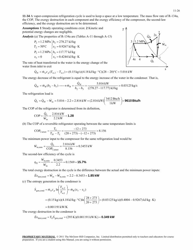
11-34 A vapor-compression refrigeration cycle is used to keep a space at a low temperature. The mass flow rate of R-134a, the COP, The exergy destruction in each component and the exergy efficiency of the compressor, the second-law efficiency, and the exergy destruction are to be determined. Assumptions 1 Steady operating conditions exist. 2 Kinetic and potential energy changes are negligible.
PROPRIETARY MATERIAL. © 2011 The McGraw-Hill Companies, Inc. Limited distribution permitted only to teachers and educators for course
Analysis (a) The properties of R-134a are (Tables A-11 through A-13)
KkJ/kg 4244.0kJ/kg 77.117
0MPa 2.1
KkJ/kg 9267.0kJ/kg 27.278
C50MPa 2.1
3
3
3
3
2
2
2
2
⋅==
⎭⎬⎫
==
⋅==
⎭⎬⎫
°==
sh
xP
sh
TP
The rate of heat transferred to the water is the energy change of the water from inlet to exit
kW 016.5C)2028(C)kJ/kg 18.4(kg/s) 15.0()( 1,2, =°−°⋅=−= wwpwH TTcmQ &&
QH
QL
1
2
3
4
1.2 MPa Win·
·
·
4s
2s
s
T
The energy decrease of the refrigerant is equal to the energy increase of the water in the condenser. That is,
kg/s 0.03125kJ/kg )77.11727.278(
kW 016.5)(32
32 =−
=−
=⎯→⎯−=hh
QmhhmQ H
RRH
&&&&
The refrigeration load is
Btu/h 9610=⎟⎠⎞
⎜⎝⎛==−=−=
kW 1Btu/h 3412kW) (2.816kW 2.8162.2016.5inWQQ HL
&&&
The COP of the refrigerator is determined from its definition,
1.28===kW 2.2
kW 816.2COPinW
QL&
&
(b) The COP of a reversible refrigerator operating between the same temperature limits is
156.8)27312()27320(
27312COPCarnot =+−−+
+−=
−=
LH
L
TTT
The minimum power input to the compressor for the same refrigeration load would be
kW 0.3453156.8
kW 816.2COPCarnot
minin, === LQW
&&
The second-law efficiency of the cycle is
15.7%==== 0.15692.2
3453.0
in
minin,II W
W&
&η
The total exergy destruction in the cycle is the difference between the actual and the minimum power inputs:
kW 1.85=−=−= 3453.02.2minin,intotaldest, WWxE &&&
(c) The entropy generation in the condenser is
kW/K 001191.0
K)kJ/kg )9267.04004.0(kg/s) 03125.0(2732027328C)lnkJ/kg 18.4(kg/s) 15.0(
)(ln 231,
2,condgen,
=
⋅−+⎟⎠⎞
⎜⎝⎛
++
°⋅=
−+⎟⎟⎠
⎞⎜⎜⎝
⎛= ssm
TT
cmS Rw
wpw &&&
The exergy destruction in the condenser is
kW 0.349=== )kW/K 001191.0)(K 293(condgen,0conddest, STxE &&
preparation. If you are a student using this Manual, you are using it without permission.
11-27
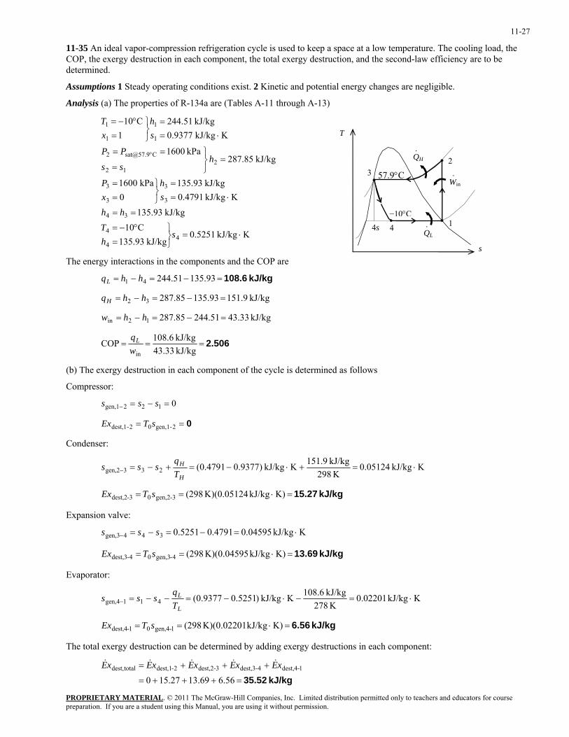
11-35 An ideal vapor-compression refrigeration cycle is used to keep a space at a low temperature. The cooling load, the COP, the exergy destruction in each component, the total exergy destruction, and the second-law efficiency are to be determined.
Assumptions 1 Steady operating conditions exist. 2 Kinetic and potential energy changes are negligible.
Analysis (a) The properties of R-134a are (Tables A-11 through A-13)
KkJ/kg 5251.0kJ/kg 93.135
C10kJ/kg 93.135
KkJ/kg 4791.0kJ/kg 93.135
0kPa 1600
kJ/kg 85.287kPa 1600
KkJ/kg 9377.0kJ/kg 51.244
1C10
44
4
34
3
3
3
3
212
1
1
1
1
⋅=⎭⎬⎫
=°−=
==
⋅==
⎭⎬⎫
==
=⎭⎬⎫
=
==
⋅==
⎭⎬⎫
=°−=
°
shT
hh
sh
xP
hss
PP
sh
xT
T
QH
QL
−10°C1
2 3
4
57.9°C
·
Win·
·4s
s The energy interactions in the components and the COP are
kJ/kg 108.6=−=−= 93.13551.24441 hhqL
kJ/kg 151.993.13585.28732 =−=−= hhqH
kJ/kg 43.3351.24485.28712in =−=−= hhw
2.506===kJ/kg 33.43kJ/kg 6.108COP
inwqL
(b) The exergy destruction in each component of the cycle is determined as follows
Compressor:
0122gen,1 =−=− sss
0== 2-gen,102-dest,1 sTEx
Condenser:
KkJ/kg 05124.0K 298
kJ/kg 9.151KkJ/kg )9377.04791.0(233gen,2 ⋅=+⋅−=+−=−H
H
Tq
sss
kJ/kg 15.27=⋅== K)kJ/kg K)(0.05124 (2983-gen,203-dest,2 sTEx
Expansion valve:
KkJ/kg 04595.04791.05251.0344gen,3 ⋅=−=−=− sss
kJ/kg 13.69=⋅== K)kJ/kg K)(0.04595 (2984-gen,304-dest,3 sTEx
Evaporator:
KkJ/kg 02201.0K 278
kJ/kg 6.108KkJ/kg )5251.09377.0(411gen,4 ⋅=−⋅−=−−=−L
L
Tq
sss
kJ/kg 6.56=⋅== K)kJ/kg K)(0.02201 (2981-gen,401-dest,4 sTEx
The total exergy destruction can be determined by adding exergy destructions in each component:
kJ/kg 35.52=+++=
+++=
56.669.1327.1501-dest,44-dest,33-dest,22-dest,1totaldest, xExExExExE &&&&&
PROPRIETARY MATERIALpreparation. If you are a student using this Manual, you are using it without permission.
. © 2011 The McGraw-Hill Companies, Inc. Limited distribution permitted only to teachers and educators for course
11-28
(c) The exergy of the heat transferred from the low-temperature medium is
kJ/kg 812.72782981kJ/kg) 6.108(1 0 =⎟
⎠⎞
⎜⎝⎛ −−=⎟⎟
⎠
⎞⎜⎜⎝
⎛−−=
LLq T
TqEx
L
The second-law efficiency of the cycle is
18.0%==== 0.180333.43
812.7
inII w
ExLqη
The total exergy destruction in the cycle can also be determined from
kJ/kg 35.52812.733.43intotaldest, =−=−=LqExwEx
The result is identical as expected.
The second-law efficiency of the compressor is determined from
[ ]
)()(
12
12012
in act,
rev
expended
recoveredCompII, hhm
ssThhmWW
XX
−−−−
===&
&
&
&
&
&η
since the compression through the compressor is isentropic (s2 = s1), the second-law efficiency is
100%==1CompII,η
The second-law efficiency of the evaporator is determined from
[ ] 14
1-dest,4
14014
0
expended
recoveredEvap II, 1
)(/)(
XXX
ssThhmTTTQ
XX LLL
&&
&
&
&
&
&
−−=
−−−−
==η
where
kJ/kg 37.14
KkJ/kg )9377.05251.0)(K 298(kJ/kg )51.24493.135()( 1401414
=⋅−−−=
−−−=− ssThhxx
Substituting,
54.4%==−=−
−= 544.0kJ/kg 14.37kJ/kg 56.611
14
1-dest,4Evap II, xx
xη
PROPRIETARY MATERIALpreparation. If you are a student using this Manual, you are using it without permission.
. © 2011 The McGraw-Hill Companies, Inc. Limited distribution permitted only to teachers and educators for course
11-29
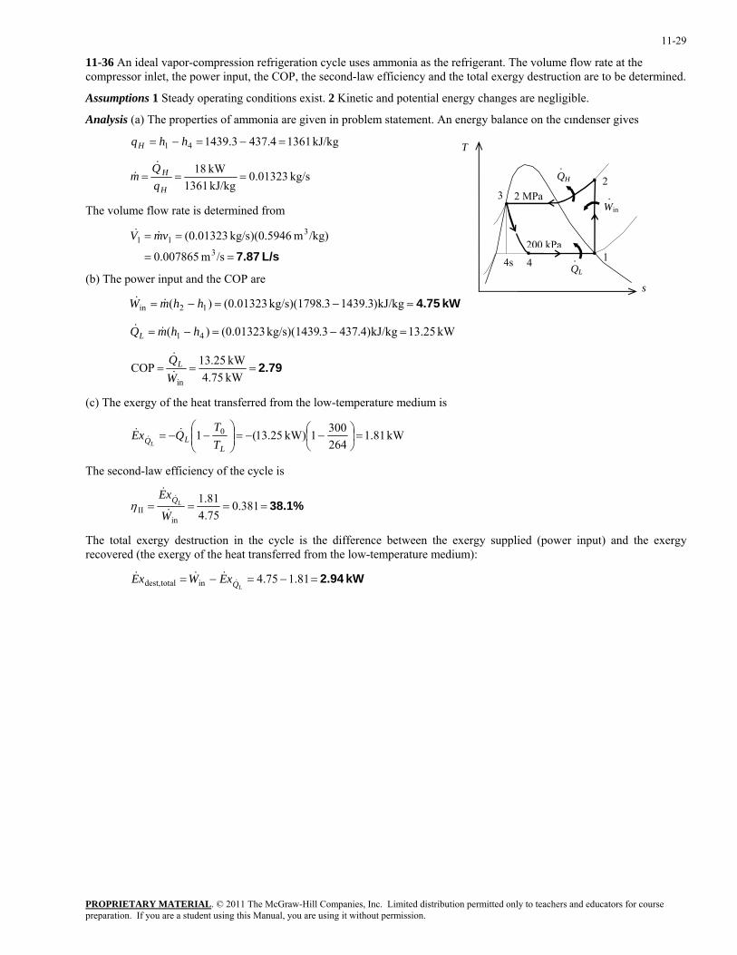
11-36 An ideal vapor-compression refrigeration cycle uses ammonia as the refrigerant. The volume flow rate at the compressor inlet, the power input, the COP, the second-law efficiency and the total exergy destruction are to be determined.
Assumptions 1 Steady operating conditions exist. 2 Kinetic and potential energy changes are negligible.
Analysis (a) The properties of ammonia are given in problem statement. An energy balance on the cındenser gives
kJ/kg 13614.4373.143941 =−=−= hhqH T
QH
QL
200 kPa1
23
4
2 MPa
·
Win·
·4s
kg/s 01323.0kJ/kg 1361kW 18
===H
H
m&
&
The volume flow rate is determined from
L/s 7.87==
==
/sm 007865.0
/kg)m 5946.0)(kg/s 01323.0(3
311 vmV &&
(b) The power input and the COP are s
kW 4.75=−=−= kJ/kg)3.1439.3kg/s)(1798 01323.0()( 12in hhmW &&
kW 13.25kJ/kg)4.437.3kg/s)(1439 01323.0()( 41 =−=−= hhmQL &&
2.79===kW 75.4kW 25.13COP
inWQL&
&
(c) The exergy of the heat transferred from the low-temperature medium is
kW 81.12643001kW) 25.13(1 0 =⎟
⎠⎞
⎜⎝⎛ −−=⎟⎟
⎠
⎞⎜⎜⎝
⎛−−=
LLQ T
TQxE
L
&&&
The second-law efficiency of the cycle is
38.1%==== 0.38175.481.1
inII W
xELQ
&
&&
η
The total exergy destruction in the cycle is the difference between the exergy supplied (power input) and the exergy recovered (the exergy of the heat transferred from the low-temperature medium):
kW 2.94=−=−= 81.175.4intotaldest, LQxEWxE &&&&
PROPRIETARY MATERIALpreparation. If you are a student using this Manual, you are using it without permission.
. © 2011 The McGraw-Hill Companies, Inc. Limited distribution permitted only to teachers and educators for course
11-30
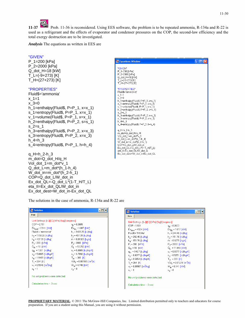
11-37 Prob. 11-36 is reconsidered. Using EES software, the problem is to be repeated ammonia, R-134a and R-22 is used as a refrigerant and the effects of evaporator and condenser pressures on the COP, the second-law efficiency and the total exergy destruction are to be investigated.
Analysis The equations as written in EES are
"GIVEN" P_1=200 [kPa] P_2=2000 [kPa] Q_dot_H=18 [kW] T_L=(-9+273) [K] T_H=(27+273) [K] "PROPERTIES" Fluid$='ammonia' x_1=1 x_3=0 h_1=enthalpy(Fluid$, P=P_1, x=x_1) s_1=entropy(Fluid$, P=P_1, x=x_1) v_1=volume(Fluid$, P=P_1, x=x_1) h_2=enthalpy(Fluid$, P=P_2, s=s_1) s_2=s_1 h_3=enthalpy(Fluid$, P=P_2, x=x_3) s_3=entropy(Fluid$, P=P_2, x=x_3) h_4=h_3 s_4=entropy(Fluid$, P=P_1, h=h_4) q_H=h_2-h_3 m_dot=Q_dot_H/q_H Vol_dot_1=m_dot*v_1 Q_dot_L=m_dot*(h_1-h_4) W_dot_in=m_dot*(h_2-h_1) COP=Q_dot_L/W_dot_in Ex_dot_QL=-Q_dot_L*(1-T_H/T_L) eta_II=Ex_dot_QL/W_dot_in Ex_dot_dest=W_dot_in-Ex_dot_QL The solutions in the case of ammonia, R-134a and R-22 are
PROPRIETARY MATERIAL. © 2011 The McGraw-Hill Companies, Inc. Limited distribution permitted only to teachers and educators for course
preparation. If you are a student using this Manual, you are using it without permission.
11-31
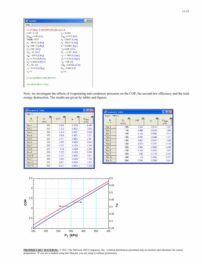
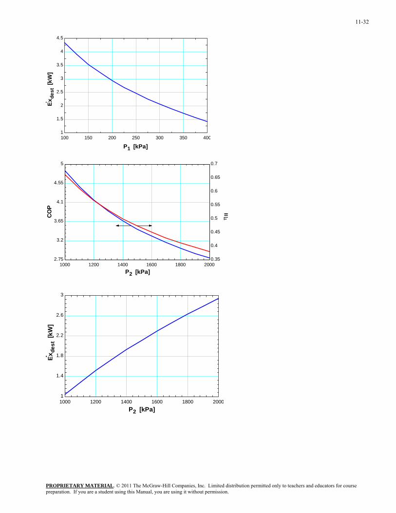
Now, we investigate the effects of evaporating and condenser pressures on the COP, the second-law efficiency and the total exergy destruction. The results are given by tables and figures.
100 150 200 250 300 350 4002
2.5
3
3.5
4
4.5
0.25
0.3
0.35
0.4
0.45
0.5
0.55
0.6
P1 [kPa]
COP
ηII
PROPRIETARY MATERIALpreparation. If you are a student using this Manual, you are using it without permission.
. © 2011 The McGraw-Hill Companies, Inc. Limited distribution permitted only to teachers and educators for course
11-32
100 150 200 250 300 350 4001
1.5
2
2.5
3
3.5
4
4.5
P1 [kPa]
Exde
st [
kW]
1000 1200 1400 1600 1800 20002.75
3.2
3.65
4.1
4.55
5
0.35
0.4
0.45
0.5
0.55
0.6
0.65
0.7
P2 [kPa]
CO
P
ηII
1000 1200 1400 1600 1800 20001
1.4
1.8
2.2
2.6
3
P2 [kPa]
Exde
st [
kW]
PROPRIETARY MATERIALpreparation. If you are a student using this Manual, you are using it without permission.
. © 2011 The McGraw-Hill Companies, Inc. Limited distribution permitted only to teachers and educators for course
11-33
Selecting the Right Refrigerant
11-38C The desirable characteristics of a refrigerant are to have an evaporator pressure which is above the atmospheric pressure, and a condenser pressure which corresponds to a saturation temperature above the temperature of the cooling medium. Other desirable characteristics of a refrigerant include being nontoxic, noncorrosive, nonflammable, chemically stable, having a high enthalpy of vaporization (minimizes the mass flow rate) and, of course, being available at low cost.
11-39C The minimum pressure that the refrigerant needs to be compressed to is the saturation pressure of the refrigerant at 30°C, which is 0.771 MPa. At lower pressures, the refrigerant will have to condense at temperatures lower than the temperature of the surroundings, which cannot happen.
11-40C Allowing a temperature difference of 10°C for effective heat transfer, the evaporation temperature of the refrigerant should be -20°C. The saturation pressure corresponding to -20°C is 0.133 MPa. Therefore, the recommended pressure would be 0.12 MPa.
11-41 A refrigerator that operates on the ideal vapor-compression cycle with refrigerant-134a is considered. Reasonable pressures for the evaporator and the condenser are to be selected.
Assumptions 1 Steady operating conditions exist. 2 Kinetic and potential energy changes are negligible.
Analysis Allowing a temperature difference of 10°C for effective heat transfer, the evaporation and condensation temperatures of the refrigerant should be -20°C and 35°C, respectively. The saturation pressures corresponding to these temperatures are 0.133 MPa and 0.888 MPa. Therefore, the recommended evaporator and condenser pressures are 0.133 MPa and 0.888 MPa, respectively.
11-42 A heat pump that operates on the ideal vapor-compression cycle with refrigerant-134a is considered. Reasonable pressures for the evaporator and the condenser are to be selected.
Assumptions 1 Steady operating conditions exist. 2 Kinetic and potential energy changes are negligible.
Analysis Allowing a temperature difference of 10°C for effective heat transfer, the evaporation and condensation temperatures of the refrigerant should be 4°C and 36°C, respectively. The saturation pressures corresponding to these temperatures are 338 kPa and 912 kPa. Therefore, the recommended evaporator and condenser pressures are 338 kPa and 912 kPa, respectively.
PROPRIETARY MATERIALpreparation. If you are a student using this Manual, you are using it without permission.
. © 2011 The McGraw-Hill Companies, Inc. Limited distribution permitted only to teachers and educators for course
11-34
Heat Pump Systems
11-43C A heat pump system is more cost effective in Miami because of the low heating loads and high cooling loads at that location.
11-44C A water-source heat pump extracts heat from water instead of air. Water-source heat pumps have higher COPs than the air-source systems because the temperature of water is higher than the temperature of air in winter.
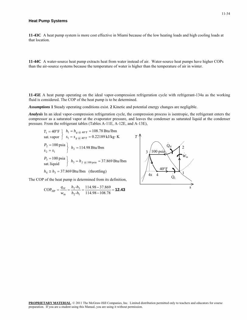
11-45E A heat pump operating on the ideal vapor-compression refrigeration cycle with refrigerant-134a as the working fluid is considered. The COP of the heat pump is to be determined.
Assumptions 1 Steady operating conditions exist. 2 Kinetic and potential energy changes are negligible.
Analysis In an ideal vapor-compression refrigeration cycle, the compression process is isentropic, the refrigerant enters the compressor as a saturated vapor at the evaporator pressure, and leaves the condenser as saturated liquid at the condenser pressure. From the refrigerant tables (Tables A-11E, A-12E, and A-13E),
)throttling( Btu/lbm 869.37
Btu/lbm 869.37 liquid sat.psia 100
Btu/lbm 98.114 psia 100
KkJ/kg 22189.0Btu/lbm 78.108
vapor sat.
F40
34
psia 100 @ 33
212
2
F40 @ 1
F40 @ 11
=≅
==⎭⎬⎫=
=⎭⎬⎫
==
⋅====
⎭⎬⎫°=
°
°
hh
hhP
hss
P
sshhT
f
g
g
QH
QL
40°F 1
2 3
4
100 psia
·
Win·
·4s
s
T
The COP of the heat pump is determined from its definition,
12.43=−−
===78.10898.114
869.3798.114COP12
32
inHP -hh
-hhwqH
PROPRIETARY MATERIALpreparation. If you are a student using this Manual, you are using it without permission.
. © 2011 The McGraw-Hill Companies, Inc. Limited distribution permitted only to teachers and educators for course
11-35
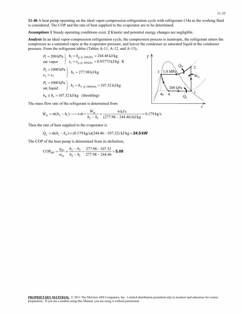
11-46 A heat pump operating on the ideal vapor-compression refrigeration cycle with refrigerant-134a as the working fluid is considered. The COP and the rate of heat supplied to the evaporator are to be determined.
Assumptions 1 Steady operating conditions exist. 2 Kinetic and potential energy changes are negligible.
Analysis In an ideal vapor-compression refrigeration cycle, the compression process is isentropic, the refrigerant enters the compressor as a saturated vapor at the evaporator pressure, and leaves the condenser as saturated liquid at the condenser pressure. From the refrigerant tables (Tables A-11, A-12, and A-13),
)throttling( kJ/kg 32.107
kJ/kg 32.107 liquid sat.kPa 1000
kJ/kg 98.277 kPa 1000
KkJ/kg 93773.0kJ/kg 46.244
vapor sat.
kPa 200
34
kPa 1000 @ 33
212
2
kPa 200 @ 1
kPa 200 @ 11
=≅
==⎭⎬⎫=
=⎭⎬⎫
==
⋅====
⎭⎬⎫=
hh
hhP
hss
P
sshhP
f
g
g
PROPRIETARY MATERIAL. © 2011 The McGraw-Hill Companies, Inc. Limited distribution permitted only to teachers and educators for course
The mass flow rate of the refrigerant is determined from
kg/s 0.179kJ/kg )46.244(277.98
kJ/s 6)(12
in12in =
−=
−=⎯→⎯−=
hhW
mhhmW&
&&&
QH
QL
200 kPa 1
23
4
1.0 MPa
·
Win·
·4s
s
T
Then the rate of heat supplied to the evaporator is
kW 24.5=−=−= kJ/kg )32.10746kg/s)(244. 179.0()( 41 hhmQL &&
The COP of the heat pump is determined from its definition,
5.09=−−
=−−
==46.24498.27732.10798.277COP
12
32
inHP hh
hhwqH
preparation. If you are a student using this Manual, you are using it without permission.
11-36
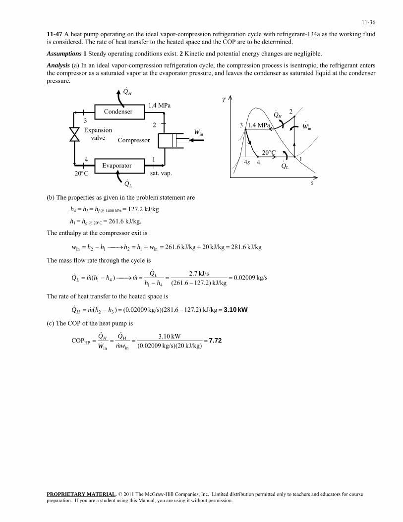
11-47 A heat pump operating on the ideal vapor-compression refrigeration cycle with refrigerant-134a as the working fluid is considered. The rate of heat transfer to the heated space and the COP are to be determined.
Assumptions 1 Steady operating conditions exist. 2 Kinetic and potential energy changes are negligible.
Analysis (a) In an ideal vapor-compression refrigeration cycle, the compression process is isentropic, the refrigerant enters the compressor as a saturated vapor at the evaporator pressure, and leaves the condenser as saturated liquid at the condenser pressure.
1
2 3
4
20°C
Condenser
Evaporator
Compressor Expansion
valve
HQ&
1.4 MPa
sat. vap.
QH
QL
20°C 1
3
4
1.4 MPa W·
in·
·
· 2
4s
s
T
inW&
LQ&
(b) The properties as given in the problem statement are
h4 = h3 = hf @ 1400 kPa = 127.2 kJ/kg
h1 = hg @ 20°C = 261.6 kJ/kg.
The enthalpy at the compressor exit is
kJ/kg 6.281kJ/kg 20kJ/kg 6.261in1212in =+=+=⎯→⎯−= whhhhw
The mass flow rate through the cycle is
kg/s 02009.0kJ/kg )2.127(261.6
kJ/s 7.2)(41
41 =−
=−
=⎯→⎯−=hh
QmhhmQ L
L
&&&&
The rate of heat transfer to the heated space is
kW 3.10=−=−= kJ/kg )2.1276kg/s)(281. 02009.0()( 32 hhmQH &&
(c) The COP of the heat pump is
7.72====kJ/kg) kg/s)(20 (0.02009
kW 3.10COPinin
HP wmQ
WQ HH
&
&
&
&
PROPRIETARY MATERIALpreparation. If you are a student using this Manual, you are using it without permission.
. © 2011 The McGraw-Hill Companies, Inc. Limited distribution permitted only to teachers and educators for course
11-37
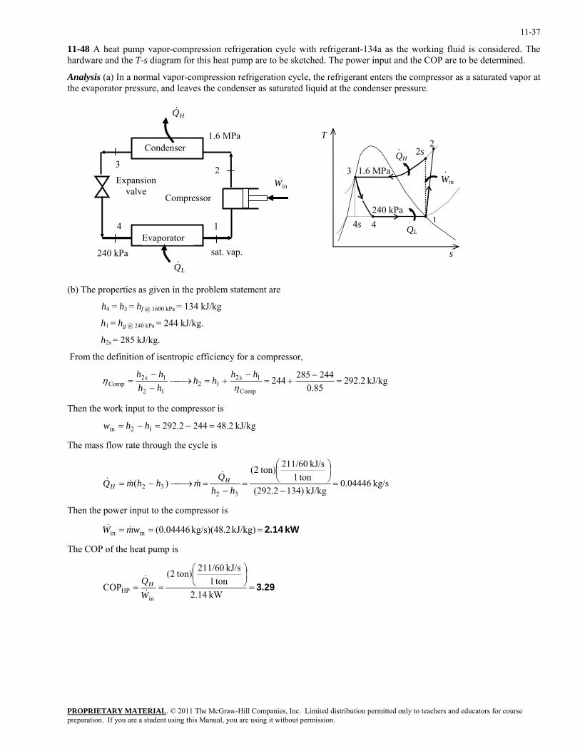
11-48 A heat pump vapor-compression refrigeration cycle with refrigerant-134a as the working fluid is considered. The hardware and the T-s diagram for this heat pump are to be sketched. The power input and the COP are to be determined.
Analysis (a) In a normal vapor-compression refrigeration cycle, the refrigerant enters the compressor as a saturated vapor at the evaporator pressure, and leaves the condenser as saturated liquid at the condenser pressure.
1 4
240 kPa sat. vap.Evaporator
Compressor
Expansion valve
2 3
Condenser
HQ&
1.6 MPa
QH
QL
240 kPa1
2
3
4
1.6 MPaWin·
·
· 2s
4s
s
T
inW&
LQ&
(b) The properties as given in the problem statement are
h4 = h3 = hf @ 1600 kPa = 134 kJ/kg
h1 = hg @ 240 kPa = 244 kJ/kg.
h2s = 285 kJ/kg.
From the definition of isentropic efficiency for a compressor,
kJ/kg 2.29285.0
244285244Comp
1212
12
12Comp =
−+=
−+=⎯→⎯
−−
=η
ηhh
hhhhhh ss
Then the work input to the compressor is
kJ/kg 2.482442.29212in =−=−= hhw
The mass flow rate through the cycle is
kg/s 04446.0kJ/kg )134(292.2
ton1kJ/s 211/60 ton)2(
)(32
32 =−
⎟⎠⎞
⎜⎝⎛
=−
=⎯→⎯−=hh
QmhhmQ H
H
&&&&
Then the power input to the compressor is
kW 2.14=== kJ/kg) kg/s)(48.2 (0.04446inin wmW &&
The COP of the heat pump is
3.29=⎟⎠⎞
⎜⎝⎛
==kW 2.14 ton1
kJ/s 211/60 ton)2(COP
inHP W
QH&
&
PROPRIETARY MATERIALpreparation. If you are a student using this Manual, you are using it without permission.
. © 2011 The McGraw-Hill Companies, Inc. Limited distribution permitted only to teachers and educators for course
11-38
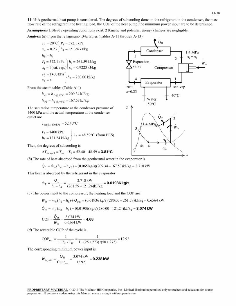
11-49 A geothermal heat pump is considered. The degrees of subcooling done on the refrigerant in the condenser, the mass flow rate of the refrigerant, the heating load, the COP of the heat pump, the minimum power input are to be determined. Assumptions 1 Steady operating conditions exist. 2 Kinetic and potential energy changes are negligible. Analysis (a) From the refrigerant-134a tables (Tables A-11 through A-13)
PROPRIETARY MATERIAL. © 2011 The McGraw-Hill Companies, Inc. Limited distribution permitted only to teachers and educators for course
kJ/kg 00.280kPa 1400
kJ/kg 9223.0kJ/kg 59.261
vap.)(sat. 1kPa 1.572
kJ/kg 24.121kPa 1.572
23.0C20
212
2
1
1
1
1
43
4
4
4
4
=⎭⎬⎫
==
==
⎭⎬⎫
==
=
==
⎭⎬⎫
=°=
hss
P
sh
xP
hhhP
xT
From the steam tables (Table A-4)
kJ/kg 53.167
kJ/kg 34.209
C40 @ 2
C50 @ 1
==
==
°
°
fw
fw
hh
hh
The saturation temperature at the condenser pressure of 1400 kPa and the actual temperature at the condenser outlet are C40.52kPa 1400 @sat °=T
C59.48 kJ/kg 24.121
kPa 14003
3
3 °=⎭⎬⎫
==
ThP
(from EES)
Then, the degrees of subcooling is C3.81°=−=−=∆ 59.4840.523satsubcool TTT
(b) The rate of heat absorbed from the geothermal water in the evaporator is
QH
QL
1
2
3
4
1.4 MPa
s
T
·
Win·
·
40°C
1.4 MPa s2 = s1
1
2 3
4
QH
20°C x=0.23
Condenser
Evaporator
Compressor Expansion valve
.
Water 50°C
Win
.
sat. vap.
4s
kW 718.2kJ/kg)53.16734kg/s)(209. 065.0()( 21 =−=−= wwwL hhmQ &&
This heat is absorbed by the refrigerant in the evaporator
kg/s 0.01936=−
=−
=)kJ/kg24.121(261.59
kW 718.2
41 hhQ
m LR
&&
(c) The power input to the compressor, the heating load and the COP are
kW 6564.0kJ/kg)59.26100kg/s)(280. 01936.0()( out12in =−=+−= QhhmW R&&&
kW 3.074=−=−= kJ/kg)24.12100kg/s)(280. 01936.0()( 32 hhmQ RH &&
4.68===kW 0.6564
kW 074.3COPin
H
WQ&
&
(d) The reversible COP of the cycle is
92.12)27350/()27325(1
1/1
1COPrev =++−
=−
=HL TT
The corresponding minimum power input is
kW 0.238===92.12kW 074.3
COPrevminin,
HQW
&&
preparation. If you are a student using this Manual, you are using it without permission.
11-39
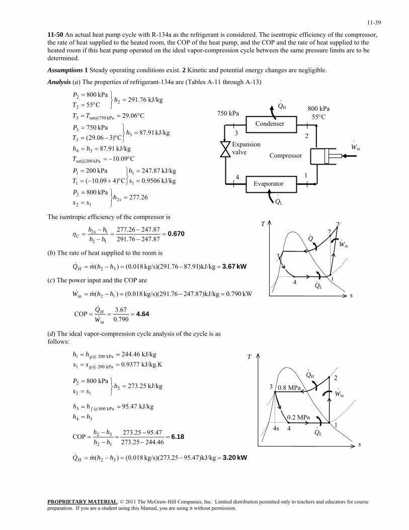
11-50 An actual heat pump cycle with R-134a as the refrigerant is considered. The isentropic efficiency of the compressor, the rate of heat supplied to the heated room, the COP of the heat pump, and the COP and the rate of heat supplied to the heated room if this heat pump operated on the ideal vapor-compression cycle between the same pressure limits are to be determined.
Assumptions 1 Steady operating conditions exist. 2 Kinetic and potential energy changes are negligible.
Analysis (a) The properties of refrigerant-134a are (Tables A-11 through A-13)
26.277kPa 800
kJ/kg 9506.0kJ/kg 87.247
C)409.10(kPa 200
C09.10kJ/kg 91.87
kJ/kg 91.87C)306.29(
kPa 750
C06.29
kJ/kg 76.291C55kPa 800
212
2
1
1
1
1
kPa sat@200
34
33
3
kPa sat@7503
22
2
=⎭⎬⎫
==
==
⎭⎬⎫
°+−==
°−===
=⎭⎬⎫
°−==
°==
=⎭⎬⎫
°==
shss
P
sh
TP
Thh
hTP
TT
hTP
.
QH
.
750 kPa
Win
.
Condenser
Evaporator
Compressor
Expansion valve
1
2 3
4
QL
800 kPa 55°C
The isentropic efficiency of the compressor is T
Q
QL
1
2
3
4
·
·2
Win·
0.670=−−
=−−
=87.24776.29187.24726.277
12
12
hhhh s
Cη
(b) The rate of heat supplied to the room is
kW 3.67=−=−= kJ/kg)91.8776kg/s)(291. 018.0()( 32 hhmQH &&
(c) The power input and the COP are
kW 790.0kJ/kg)87.24776kg/s)(291. 018.0()( 12in =−=−= hhmW && s
4.64===790.067.3COP
inWQH&
&
(d) The ideal vapor-compression cycle analysis of the cycle is as follows:
kJ/kg.K 9377.0kJ/kg 46.244
kPa 200 @1
kPa 200 @1
==
==
g
g
sshh T
QH
QL
0.2 MPa 1
23
4
0.8 MPa
·
Win·
·4s
kJ/kg 25.273kPa 800
212
2 =⎭⎬⎫
==
hss
P
34
kPa 800 @3 kJ/kg 47.95hhhh f
=
==
6.18=−−
=−−
=46.24425.273
47.9525.273COP12
32
hhhh
s
kW 3.20=−=−= kJ/kg)47.9525kg/s)(273. 018.0()( 32 hhmQH &&
PROPRIETARY MATERIALpreparation. If you are a student using this Manual, you are using it without permission.
. © 2011 The McGraw-Hill Companies, Inc. Limited distribution permitted only to teachers and educators for course
11-40
Innovative Refrigeration Systems
11-51C Performing the refrigeration in stages is called cascade refrigeration. In cascade refrigeration, two or more refrigeration cycles operate in series. Cascade refrigerators are more complex and expensive, but they have higher COP's, they can incorporate two or more different refrigerants, and they can achieve much lower temperatures.
11-52C Cascade refrigeration systems have higher COPs than the ordinary refrigeration systems operating between the same pressure limits.
11-53C The saturation pressure of refrigerant-134a at -32°C is 77 kPa, which is below the atmospheric pressure. In reality a pressure below this value should be used. Therefore, a cascade refrigeration system with a different refrigerant at the bottoming cycle is recommended in this case.
11-54C We would favor the two-stage compression refrigeration system with a flash chamber since it is simpler, cheaper, and has better heat transfer characteristics.
11-55C Yes, by expanding the refrigerant in stages in several throttling devices.
11-56C To take advantage of the cooling effect by throttling from high pressures to low pressures.
PROPRIETARY MATERIALpreparation. If you are a student using this Manual, you are using it without permission.
. © 2011 The McGraw-Hill Companies, Inc. Limited distribution permitted only to teachers and educators for course
11-41
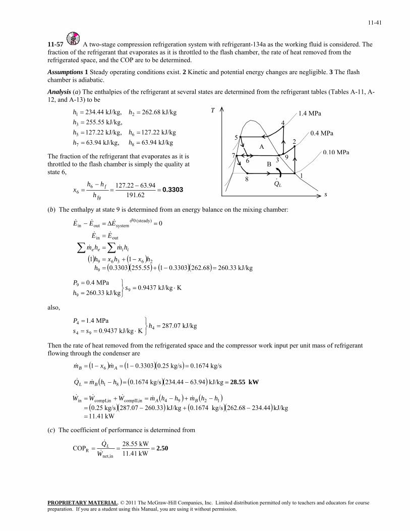
11-57 A two-stage compression refrigeration system with refrigerant-134a as the working fluid is considered. The fraction of the refrigerant that evaporates as it is throttled to the flash chamber, the rate of heat removed from the refrigerated space, and the COP are to be determined.
Assumptions 1 Steady operating conditions exist. 2 Kinetic and potential energy changes are negligible. 3 The flash chamber is adiabatic.
Analysis (a) The enthalpies of the refrigerant at several states are determined from the refrigerant tables (Tables A-11, A-12, and A-13) to be
T
QL
0.10 MPa
1
2 5
8
0.4 MPa
1.4 MPa
·
9 67
3B
A
4
kJ/kg 94.63kJ/kg 22.127
kJ/kg 68.262
,kJ/kg 94.63,kJ/kg 22.127,kJ/kg 55.255
kJ/kg, 44.234
8
6
2
7
5
3
1
==
=
====
hh
h
hhhh
The fraction of the refrigerant that evaporates as it is throttled to the flash chamber is simply the quality at state 6,
0.3303=−
=−
=62.191
94.6322.12766
fg
f
hhh
x s
(b) The enthalpy at state 9 is determined from an energy balance on the mixing chamber:
( ) ( )( )( ) ( )( ) kJ/kg 33.26068.2623303.0155.2553303.0
11
0
9
26369
outin
(steady) 0systemoutin
=−+=−+=
=
=
=∆=−
∑∑h
hxhxh
hmhm
EE
EEE
iiee &&
&&
&&&
KkJ/kg 9437.0kJ/kg 33.260
MPa 4.09
9
9 ⋅=⎭⎬⎫
==
shP
also,
kJ/kg 07.287KkJ/kg 9437.0
MPa 4.14
94
4 =⎭⎬⎫
⋅===
hss
P
Then the rate of heat removed from the refrigerated space and the compressor work input per unit mass of refrigerant flowing through the condenser are
( ) ( )( )
( ) ( )( )
( ) ( )( )( ) ( )( )
kW .4111kJ/kg 234.44262.68kg/s 0.1674kJ/kg 260.33287.07kg/s 0.25
kJ/kg 3.946234.44kg/s 0.1674
kg/s 0.1674kg/s 0.253303.011
1294incompII,incompI,in
81
6
=−+−=
−+−=+=
=−=−=
=−=−=
hhmhhmWWW
hhmQ
mxm
BA
BL
AB
&&&&&
&&
&&
kW 28.55
(c) The coefficient of performance is determined from
2.50===kW 11.41kW 28.55
COPinnet,
R WQL&
&
PROPRIETARY MATERIALpreparation. If you are a student using this Manual, you are using it without permission.
. © 2011 The McGraw-Hill Companies, Inc. Limited distribution permitted only to teachers and educators for course
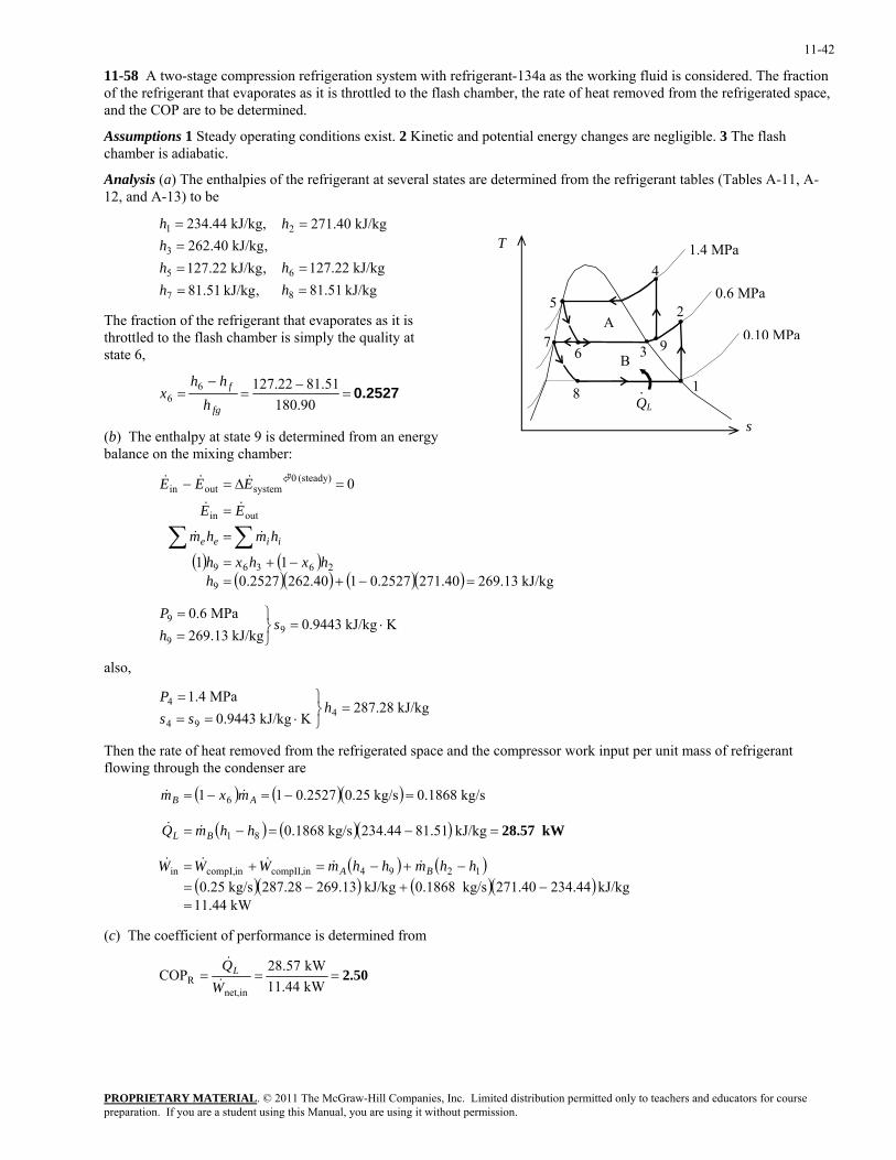
11-42
11-58 A two-stage compression refrigeration system with refrigerant-134a as the working fluid is considered. The fraction of the refrigerant that evaporates as it is throttled to the flash chamber, the rate of heat removed from the refrigerated space, and the COP are to be determined.
Assumptions 1 Steady operating conditions exist. 2 Kinetic and potential energy changes are negligible. 3 The flash chamber is adiabatic.
Analysis (a) The enthalpies of the refrigerant at several states are determined from the refrigerant tables (Tables A-11, A-12, and A-13) to be
kJ/kg 51.81kJ/kg 22.127
kJ/kg 40.271
,kJ/kg 51.81,kJ/kg 22.127,kJ/kg 40.262
kJ/kg, 44.234
8
6
2
7
5
3
1
==
=
====
hh
h
hhhh
T
QL
0.10 MPa
1
2 5
8
0.6 MPa
1.4 MPa
·
9 67
3 B
A
4
The fraction of the refrigerant that evaporates as it is throttled to the flash chamber is simply the quality at state 6,
0.2527=−
=−
=90.180
51.8122.12766
fg
f
hhh
x
s (b) The enthalpy at state 9 is determined from an energy balance on the mixing chamber:
( ) ( )( )( ) ( )( ) kJ/kg 13.26940.2712527.0140.2622527.0
11
0
9
26369
outin
(steady) 0systemoutin
=−+=−+=
=
=
=∆=−
∑∑h
hxhxh
hmhm
EE
EEE
iiee &&
&&
&&&
KkJ/kg 9443.0kJ/kg 13.269
MPa 6.09
9
9 ⋅=⎭⎬⎫
==
shP
also,
kJ/kg 28.287KkJ/kg 9443.0
MPa 4.14
94
4 =⎭⎬⎫
⋅===
hss
P
Then the rate of heat removed from the refrigerated space and the compressor work input per unit mass of refrigerant flowing through the condenser are
( ) ( )( )
( ) ( )( )
( ) ( )( )( ) ( )( )
kW .4411kJ/kg 234.44271.40kg/s 0.1868kJ/kg 269.13287.28kg/s 0.25
kJ/kg .5181234.44kg/s 0.1868
kg/s 0.1868kg/s 0.252527.011
1294incompII,incompI,in
81
6
=−+−=
−+−=+=
=−=−=
=−=−=
hhmhhmWWW
hhmQ
mxm
BA
BL
AB
&&&&&
&&
&&
kW 28.57
(c) The coefficient of performance is determined from
2.50===kW 11.44kW 28.57
COPinnet,
R WQL&
&
PROPRIETARY MATERIALpreparation. If you are a student using this Manual, you are using it without permission.
. © 2011 The McGraw-Hill Companies, Inc. Limited distribution permitted only to teachers and educators for course
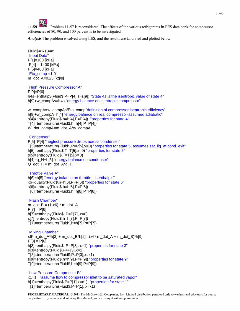
11-43
11-59 Problem 11-57 is reconsidered. The effects of the various refrigerants in EES data bank for compressor efficiencies of 80, 90, and 100 percent is to be investigated.
Analysis The problem is solved using EES, and the results are tabulated and plotted below.
Fluid$='R134a' "Input Data" P[1]=100 [kPa] P[4] = 1400 [kPa] P[6]=400 [kPa] "Eta_comp =1.0" m_dot_A=0.25 [kg/s] "High Pressure Compressor A" P[9]=P[6] h4s=enthalpy(Fluid$,P=P[4],s=s[9]) "State 4s is the isentropic value of state 4" h[9]+w_compAs=h4s "energy balance on isentropic compressor" w_compA=w_compAs/Eta_comp"definition of compressor isentropic efficiency" h[9]+w_compA=h[4] "energy balance on real compressor-assumed adiabatic" s[4]=entropy(Fluid$,h=h[4],P=P[4]) "properties for state 4" T[4]=temperature(Fluid$,h=h[4],P=P[4]) W_dot_compA=m_dot_A*w_compA "Condenser" P[5]=P[4] "neglect pressure drops across condenser" T[5]=temperature(Fluid$,P=P[5],x=0) "properties for state 5, assumes sat. liq. at cond. exit" h[5]=enthalpy(Fluid$,T=T[5],x=0) "properties for state 5" s[5]=entropy(Fluid$,T=T[5],x=0) h[4]=q_H+h[5] "energy balance on condenser" Q_dot_H = m_dot_A*q_H "Throttle Valve A" h[6]=h[5] "energy balance on throttle - isenthalpic" x6=quality(Fluid$,h=h[6],P=P[6]) "properties for state 6" s[6]=entropy(Fluid$,h=h[6],P=P[6]) T[6]=temperature(Fluid$,h=h[6],P=P[6]) "Flash Chamber" m_dot_B = (1-x6) * m_dot_A P[7] = P[6] h[7]=enthalpy(Fluid$, P=P[7], x=0) s[7]=entropy(Fluid$,h=h[7],P=P[7]) T[7]=temperature(Fluid$,h=h[7],P=P[7]) "Mixing Chamber" x6*m_dot_A*h[3] + m_dot_B*h[2] =(x6* m_dot_A + m_dot_B)*h[9] P[3] = P[6] h[3]=enthalpy(Fluid$, P=P[3], x=1) "properties for state 3" s[3]=entropy(Fluid$,P=P[3],x=1) T[3]=temperature(Fluid$,P=P[3],x=x1) s[9]=entropy(Fluid$,h=h[9],P=P[9]) "properties for state 9" T[9]=temperature(Fluid$,h=h[9],P=P[9]) "Low Pressure Compressor B" x1=1 "assume flow to compressor inlet to be saturated vapor" h[1]=enthalpy(Fluid$,P=P[1],x=x1) "properties for state 1" T[1]=temperature(Fluid$,P=P[1], x=x1)
PROPRIETARY MATERIALpreparation. If you are a student using this Manual, you are using it without permission.
. © 2011 The McGraw-Hill Companies, Inc. Limited distribution permitted only to teachers and educators for course
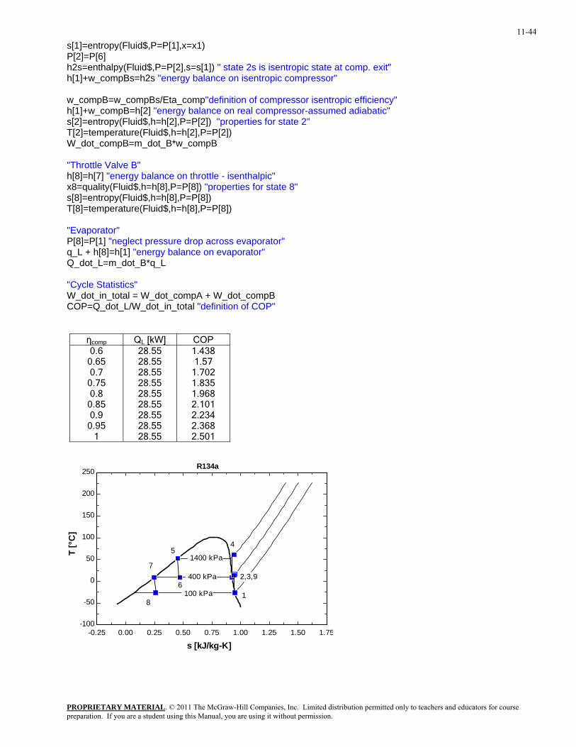
11-44
s[1]=entropy(Fluid$,P=P[1],x=x1) P[2]=P[6] h2s=enthalpy(Fluid$,P=P[2],s=s[1]) " state 2s is isentropic state at comp. exit" h[1]+w_compBs=h2s "energy balance on isentropic compressor" w_compB=w_compBs/Eta_comp"definition of compressor isentropic efficiency" h[1]+w_compB=h[2] "energy balance on real compressor-assumed adiabatic" s[2]=entropy(Fluid$,h=h[2],P=P[2]) "properties for state 2" T[2]=temperature(Fluid$,h=h[2],P=P[2]) W_dot_compB=m_dot_B*w_compB "Throttle Valve B" h[8]=h[7] "energy balance on throttle - isenthalpic" x8=quality(Fluid$,h=h[8],P=P[8]) "properties for state 8" s[8]=entropy(Fluid$,h=h[8],P=P[8]) T[8]=temperature(Fluid$,h=h[8],P=P[8]) "Evaporator" P[8]=P[1] "neglect pressure drop across evaporator" q_L + h[8]=h[1] "energy balance on evaporator" Q_dot_L=m_dot_B*q_L "Cycle Statistics" W_dot_in_total = W_dot_compA + W_dot_compB COP=Q_dot_L/W_dot_in_total "definition of COP"
ηcomp QL [kW] COP 0.6
0.65 0.7
0.75 0.8
0.85 0.9
0.95 1
28.55 28.55 28.55 28.55 28.55 28.55 28.55 28.55 28.55
1.438 1.57
1.702 1.835 1.968 2.101 2.234 2.368 2.501
-0.25 0.00 0.25 0.50 0.75 1.00 1.25 1.50 1.75-100
-50
0
50
100
150
200
250
s [kJ/kg-K]
T [°
C]
1400 kPa
400 kPa
100 kPa
R134a
1
2,3,9
45
6
7
8
PROPRIETARY MATERIALpreparation. If you are a student using this Manual, you are using it without permission.
. © 2011 The McGraw-Hill Companies, Inc. Limited distribution permitted only to teachers and educators for course
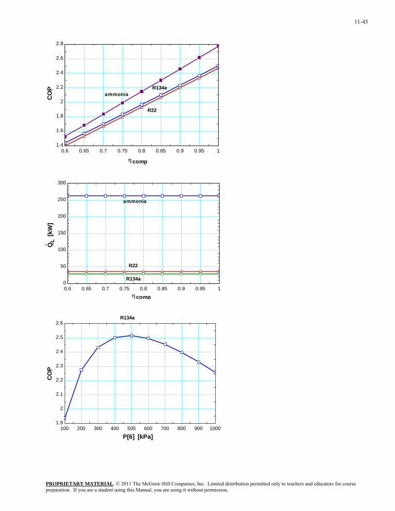
11-45
0.6 0.65 0.7 0.75 0.8 0.85 0.9 0.95 11.4
1.6
1.8
2
2.2
2.4
2.6
2.8
ηcomp
CO
P
R134a
R22
ammonia
0.6 0.65 0.7 0.75 0.8 0.85 0.9 0.95 10
50
100
150
200
250
300
ηcomp
QL
[kW
]
ammonia
R22
R134a
100 200 300 400 500 600 700 800 900 10001.9
2
2.1
2.2
2.3
2.4
2.5
2.6
P[6] [kPa]
CO
P
R134a
PROPRIETARY MATERIALpreparation. If you are a student using this Manual, you are using it without permission.
. © 2011 The McGraw-Hill Companies, Inc. Limited distribution permitted only to teachers and educators for course
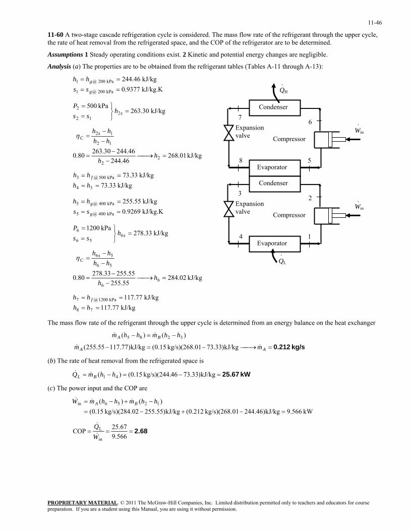
11-46
11-60 A two-stage cascade refrigeration cycle is considered. The mass flow rate of the refrigerant through the upper cycle, the rate of heat removal from the refrigerated space, and the COP of the refrigerator are to be determined.
Assumptions 1 Steady operating conditions exist. 2 Kinetic and potential energy changes are negligible.
Analysis (a) The properties are to be obtained from the refrigerant tables (Tables A-11 through A-13):
kJ/kg.K 9377.0kJ/kg 46.244
kPa 200 @1
kPa 200 @1
==
==
g
g
sshh
.
5
6 7
8
QH
Condenser
Evaporator
Compressor
Expansion valve
.
Win
1
2 3
4
Win
.
.
Condenser
Evaporator
Compressor
Expansion valve
QL
kJ/kg 30.263kPa 500
212
2 =⎭⎬⎫
==
shss
P
kJ/kg 01.268
46.24446.24430.26380.0 2
2
12
12
=⎯→⎯−
−=
−−
=
hh
hhhh s
Cη
kJ/kg 33.73
kJ/kg 33.73
34
kPa 500 @3
==
==
hhhh f
kJ/kg.K 9269.0kJ/kg 55.255
kPa 400 @5
kPa 004 @5
==
==
g
g
sshh
kJ/kg 33.278kPa 1200
656
6 =⎭⎬⎫
==
shss
P
kJ/kg 02.284
55.25555.25533.27880.0 6
6
56
56
=⎯→⎯−
−=
−−
=
hh
hhhh s
Cη
kJ/kg 77.117
kJ/kg 77.117
78
kPa 1200 @7
==
==
hhhh f
The mass flow rate of the refrigerant through the upper cycle is determined from an energy balance on the heat exchanger
kg/s 0.212=⎯→⎯−=−
−=−
AA
BA
mm
hhmhhm
&&
&&
kJ/kg)33.7301kg/s)(268. 15.0(kJ/kg)77.117.55255(
)()( 3285
(b) The rate of heat removal from the refrigerated space is
kW 25.67=−=−= kJ/kg)33.7346kg/s)(244. 15.0()( 41 hhmQ BL &&
(c) The power input and the COP are
kW 566.9kJ/kg)46.24401kg/s)(268. 212.0(kJ/kg)55.25502kg/s)(284. 15.0()()( 1256in
=−+−=−+−= hhmhhmW BA &&&
2.68===566.9
67.25COPin
L
WQ&
&
PROPRIETARY MATERIALpreparation. If you are a student using this Manual, you are using it without permission.
. © 2011 The McGraw-Hill Companies, Inc. Limited distribution permitted only to teachers and educators for course
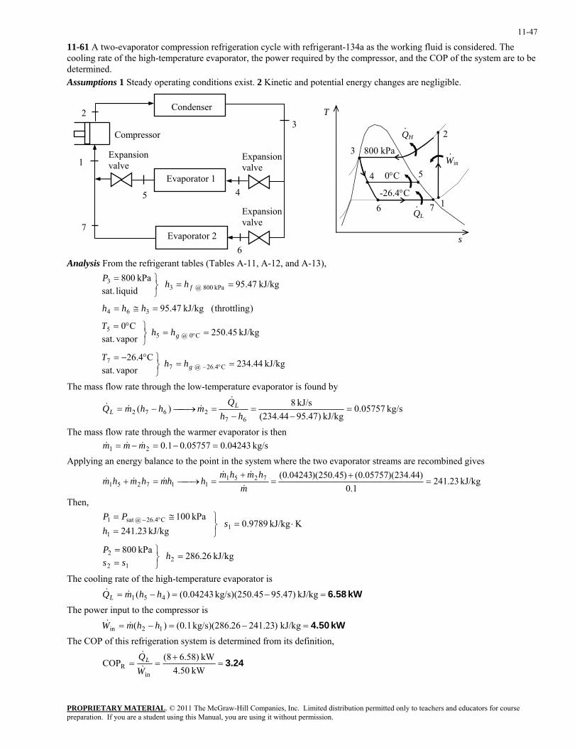
11-47
11-61 A two-evaporator compression refrigeration cycle with refrigerant-134a as the working fluid is considered. The cooling rate of the high-temperature evaporator, the power required by the compressor, and the COP of the system are to be determined. Assumptions 1 Steady operating conditions exist. 2 Kinetic and potential energy changes are negligible.
45
6
Compressor
Expansion valve1
2
Evaporator 2
Expansion valve
Expansion valve
Condenser
Evaporator 1
7
QH
QL
-26.4°C 1
2
3
6
800 kPaWin·
·
·
4 5
7
0°C
s
T 3 Analysis From the refrigerant tables (Tables A-11, A-12, and A-13),
kJ/kg 44.234 vapor sat.
C4.26
kJ/kg 45.250 vapor sat.
C0
)throttling( kJ/kg 47.95
kJ/kg 47.95 liquid sat.kPa 800
C4.26 @ 77
C0 @ 55
364
kPa 800 @ 33
==⎭⎬⎫°−=
==⎭⎬⎫°=
=≅=
==⎭⎬⎫=
°−
°
g
g
f
hhT
hhT
hhh
hhP
The mass flow rate through the low-temperature evaporator is found by
kg/s 05757.0kJ/kg )47.95(234.44
kJ/s 8)(67
2672 =−
=−
=⎯→⎯−=hh
QmhhmQ L
L
&&&&
The mass flow rate through the warmer evaporator is then kg/s 04243.005757.01.021 =−=−= mmm &&& Applying an energy balance to the point in the system where the two evaporator streams are recombined gives
kJ/kg 23.2411.0
)44.234)(05757.0()45.250)(04243.0(7251117251 =
+=
+=⎯→⎯=+
mhmhm
hhmhmhm&
&&&&&
Then,
kJ/kg 26.286 kPa 800
KkJ/kg 9789.0 kJ/kg 23.241
kPa 100
212
2
11
C26.4 @sat 1
=⎭⎬⎫
==
⋅=⎭⎬⎫
=≅= °−
hss
P
sh
PP
The cooling rate of the high-temperature evaporator is
kW 6.58=−=−= kJ/kg )47.95(250.45)kg/s 04243.0()( 451 hhmQL &&
The power input to the compressor is
kW 4.50=−=−= kJ/kg )23.24126kg/s)(286. 1.0()( 12in hhmW &&
The COP of this refrigeration system is determined from its definition,
3.24=+
==kW 4.50
kW 6.58)(8COP
inR W
QL&
&
PROPRIETARY MATERIALpreparation. If you are a student using this Manual, you are using it without permission.
. © 2011 The McGraw-Hill Companies, Inc. Limited distribution permitted only to teachers and educators for course
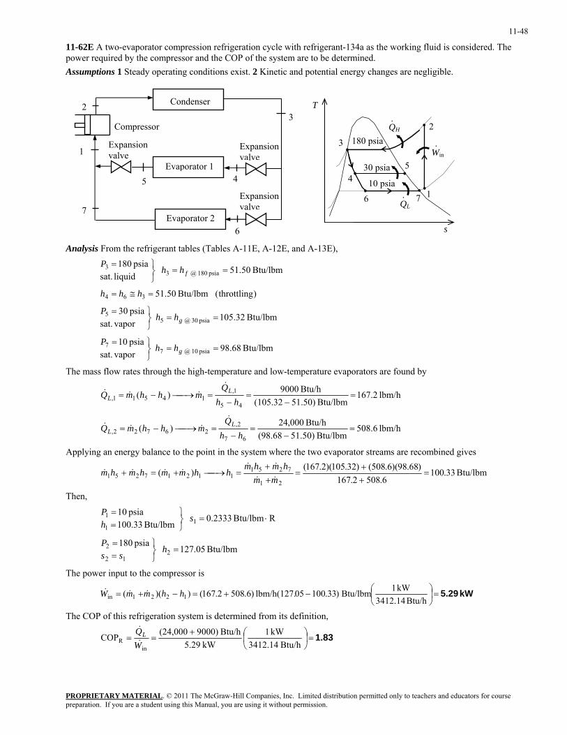
11-48
11-62E A two-evaporator compression refrigeration cycle with refrigerant-134a as the working fluid is considered. The power required by the compressor and the COP of the system are to be determined. Assumptions 1 Steady operating conditions exist. 2 Kinetic and potential energy changes are negligible.
45
6
Compressor
Expansion valve1
2
Evaporator 2
Expansion valve
Expansion valve
Condenser
Evaporator 1
7
QH
QL
10 psia 1
2
3
6
180 psia Win·
·
·
45
7
30 psia
s
T 3 Analysis From the refrigerant tables (Tables A-11E, A-12E, and A-13E),
Btu/lbm 68.98 vapor sat.
psia 10
Btu/lbm 32.105 vapor sat.
psia 30
)throttling( Btu/lbm 50.51
Btu/lbm 50.51 liquid sat.psia 180
psia 10 @ 77
psia 03 @ 55
364
psia 180 @ 33
==⎭⎬⎫=
==⎭⎬⎫=
=≅=
==⎭⎬⎫=
g
g
f
hhP
hhP
hhh
hhP
The mass flow rates through the high-temperature and low-temperature evaporators are found by
lbm/h 2.167Btu/lbm )50.51(105.32
Btu/h 9000)(45
1,14511, =
−=
−=⎯→⎯−=
hhQ
mhhmQ LL
&&&&
lbm/h 6.508Btu/lbm )50.51(98.68
Btu/h 000,24)(67
2,26722, =
−=
−=⎯→⎯−=
hhQ
mhhmQ LL
&&&&
Applying an energy balance to the point in the system where the two evaporator streams are recombined gives
Btu/lbm 33.1006.5082.167
)68.98)(6.508()32.105)(2.167()(21
725111217251 =
++
=++
=⎯→⎯+=+mm
hmhmhhmmhmhm
&&
&&&&&&
Then,
Btu/lbm 05.127 psia 180
RBtu/lbm 2333.0 Btu/lbm 33.100
psia 10
212
2
11
1
=⎭⎬⎫
==
⋅=⎭⎬⎫
==
hss
P
shP
The power input to the compressor is
kW 5.29=⎟⎠⎞
⎜⎝⎛−+=−+=
Btu/h 3412.14kW 1Btu/lbm )33.10005lbm/h(127. )6.5082.167())(( 1221in hhmmW &&&
The COP of this refrigeration system is determined from its definition,
1.83=⎟⎠⎞
⎜⎝⎛+
==Btu/h 3412.14
kW 1kW 5.29
Btu/h 000)9(24,000COPin
R WQL&
&
PROPRIETARY MATERIALpreparation. If you are a student using this Manual, you are using it without permission.
. © 2011 The McGraw-Hill Companies, Inc. Limited distribution permitted only to teachers and educators for course
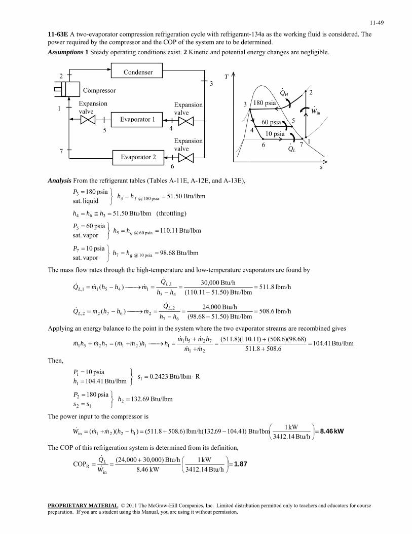
11-49
11-63E A two-evaporator compression refrigeration cycle with refrigerant-134a as the working fluid is considered. The power required by the compressor and the COP of the system are to be determined. Assumptions 1 Steady operating conditions exist. 2 Kinetic and potential energy changes are negligible.
45
6
Compressor
Expansion valve1
2
Evaporator 2
Expansion valve
Expansion valve
Condenser
Evaporator 1
7
QH
QL
10 psia 1
2
3
6
180 psia Win·
·
·
45
7
60 psia
s
T 3 Analysis From the refrigerant tables (Tables A-11E, A-12E, and A-13E),
Btu/lbm 68.98 vapor sat.
psia 10
Btu/lbm 11.110 vapor sat.
psia 60
)throttling( Btu/lbm 50.51
Btu/lbm 50.51 liquid sat.psia 180
psia 10 @ 77
psia 06 @ 55
364
psia 180 @ 33
==⎭⎬⎫=
==⎭⎬⎫=
=≅=
==⎭⎬⎫=
g
g
f
hhP
hhP
hhh
hhP
The mass flow rates through the high-temperature and low-temperature evaporators are found by
lbm/h 8.511Btu/lbm )50.51(110.11
Btu/h 000,30)(45
1,14511, =
−=
−=⎯→⎯−=
hhQ
mhhmQ LL
&&&&
lbm/h 6.508Btu/lbm )50.51(98.68
Btu/h 000,24)(67
2,26722, =
−=
−=⎯→⎯−=
hhQ
mhhmQ LL
&&&&
Applying an energy balance to the point in the system where the two evaporator streams are recombined gives
Btu/lbm 41.1046.5088.511
)68.98)(6.508()11.110)(8.511()(21
725111217251 =
++
=++
=⎯→⎯+=+mm
hmhmhhmmhmhm
&&
&&&&&&
Then,
Btu/lbm 69.132 psia 180
RBtu/lbm 2423.0 Btu/lbm 41.104
psia 10
212
2
11
1
=⎭⎬⎫
==
⋅=⎭⎬⎫
==
hss
P
shP
The power input to the compressor is
kW 8.46=⎟⎠⎞
⎜⎝⎛−+=−+=
Btu/h 3412.14kW 1Btu/lbm )41.10469lbm/h(132. )6.5088.511())(( 1221in hhmmW &&&
The COP of this refrigeration system is determined from its definition,
1.87=⎟⎠⎞
⎜⎝⎛+
==Btu/h 3412.14
kW 1kW 8.46
Btu/h 000),30(24,000COPin
R WQL&
&
PROPRIETARY MATERIALpreparation. If you are a student using this Manual, you are using it without permission.
. © 2011 The McGraw-Hill Companies, Inc. Limited distribution permitted only to teachers and educators for course
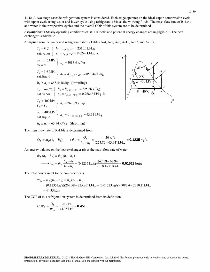
11-50
11-64 A two-stage cascade refrigeration system is considered. Each stage operates on the ideal vapor-compression cycle with upper cycle using water and lower cycle using refrigerant-134a as the working fluids. The mass flow rate of R-134a and water in their respective cycles and the overall COP of this system are to be determined.
Assumptions 1 Steady operating conditions exist. 2 Kinetic and potential energy changes are negligible. 3 The heat exchanger is adiabatic.
Analysis From the water and refrigerant tables (Tables A-4, A-5, A-6, A-11, A-12, and A-13),
)throttling( kJ/kg 94.63
kJ/kg 94.63 liquid sat.kPa 400
kJ/kg 59.267 kPa 400
KkJ/kg 96866.0kJ/kg 86.225
vapor sat.
C40
)throttling( kJ/kg 44.858
kJ/kg 44.858 liquid sat.
MPa 6.1
kJ/kg 4.5083 MPa 6.1
KkJ/kg 0249.9kJ/kg 1.2510
vapor sat.
C5
78
kPa 040 @ 77
656
6
C40 @ 5
C40 @ 55
34
MPa 6.1 @ 33
212
2
C5 @ 1
C5 @ 11
=≅
==⎭⎬⎫=
=⎭⎬⎫
==
⋅====
⎭⎬⎫°−=
=≅
==⎭⎬⎫=
=⎭⎬⎫
==
⋅====
⎭⎬⎫°=
°−
°−
°
°
hh
hhP
hss
P
sshhT
hh
hhP
hss
P
sshhT
f
g
g
f
g
g
QL-40°C 5
6 3
8 ·
4 400 kPa 5°C
71
1.6 MPa2
s
T
The mass flow rate of R-134a is determined from
kg/s 0.1235=−
=−
=⎯→⎯−=kJ/kg )94.63(225.86
kJ/s 20)(85
85 hhQ
mhhmQ LRRL
&&&&
An energy balance on the heat exchanger gives the mass flow rate of water
kg/s 0.01523=−−
=−−
=⎯→⎯
−=−
44.8581.251094.6359.267kg/s) 1235.0(
)()(
41
76
4176
hhhh
mm
hhmhhm
Rw
wR
&&
&&
The total power input to the compressors is
kJ/s 35.44
kJ/kg )1.2510.4kg/s)(5083 01523.0(kJ/kg )86.22559kg/s)(267. 1235.0()()( 1256in
=−+−=
−+−= hhmhhmW wR &&&
The COP of this refrigeration system is determined from its definition,
0.451===kJ/s 44.35
kJ/s 20COPin
R WQL&
&
PROPRIETARY MATERIALpreparation. If you are a student using this Manual, you are using it without permission.
. © 2011 The McGraw-Hill Companies, Inc. Limited distribution permitted only to teachers and educators for course
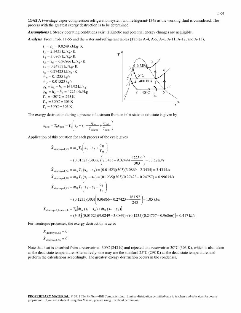
11-51
11-65 A two-stage vapor-compression refrigeration system with refrigerant-134a as the working fluid is considered. The process with the greatest exergy destruction is to be determined.
Assumptions 1 Steady operating conditions exist. 2 Kinetic and potential energy changes are negligible.
Analysis From Prob. 11-55 and the water and refrigerant tables (Tables A-4, A-5, A-6, A-11, A-12, and A-13),
K 303C30K 303C30K 243C30
kJ/kg 0.4225kJ/kg 92.161
kg/s 01523.0kg/s 1235.0
KkJ/kg 27423.0KkJ/kg 24757.0
KkJ/kg 96866.0KkJ/kg 0869.3KkJ/kg 3435.2
KkJ/kg 0249.9
0
32
85
8
7
65
4
3
21
=°==°==°−=
=−==−=
==
⋅=⋅=
⋅==⋅=⋅=
⋅==
TTT
hhqhhq
mmss
ssss
ss
H
L
H
L
w
R&&
QL-40°C 5
63
8 ·
4 400 kPa 5°C
71
1.6 MPa2
s
T
The exergy destruction during a process of a stream from an inlet state to exit state is given by
⎟⎟⎠
⎞⎜⎜⎝
⎛+−−==
sink
out
source
in0gen0dest T
qT
qssTsTx ie
Application of this equation for each process of the cycle gives
[ ][ ] kJ/s 417.0)96866.024757.0)(1235.0()0869.30249.9)(01523.0()303(
)()(
kJ/s 05.1243
92.16127423.096866.0)303)(1235.0(
kJ/s 996.0)24757.027423.0)(303)(1235.0()(
kJ/s 43.3)3435.20869.3)(303)(01523.0()(
kJ/s 52.33303
0.42250249.93435.2)K 303)(01523.0(
67R41w0exchheat destroyed,
850R85 destroyed,
780R78 destroyed,
340w34 destroyed,
23023 destroyed,
=−+−=
−+−=
=⎟⎠⎞
⎜⎝⎛ −−=
⎟⎟⎠
⎞⎜⎜⎝
⎛−−=
=−=−=
=−=−=
=⎟⎠⎞
⎜⎝⎛ +−=
⎟⎟⎠
⎞⎜⎜⎝
⎛+−=
ssmssmTX
Tq
ssTmX
ssTmX
ssTmX
Tq
ssTmX
L
L
H
Hw
&&&
&&
&&
&&
&&
For isentropic processes, the exergy destruction is zero:
0
0
56 destroyed,
12 destroyed,
=
=
X
X&
&
Note that heat is absorbed from a reservoir at -30°C (243 K) and rejected to a reservoir at 30°C (303 K), which is also taken as the dead state temperature. Alternatively, one may use the standard 25°C (298 K) as the dead state temperature, and perform the calculations accordingly. The greatest exergy destruction occurs in the condenser.
PROPRIETARY MATERIALpreparation. If you are a student using this Manual, you are using it without permission.
. © 2011 The McGraw-Hill Companies, Inc. Limited distribution permitted only to teachers and educators for course
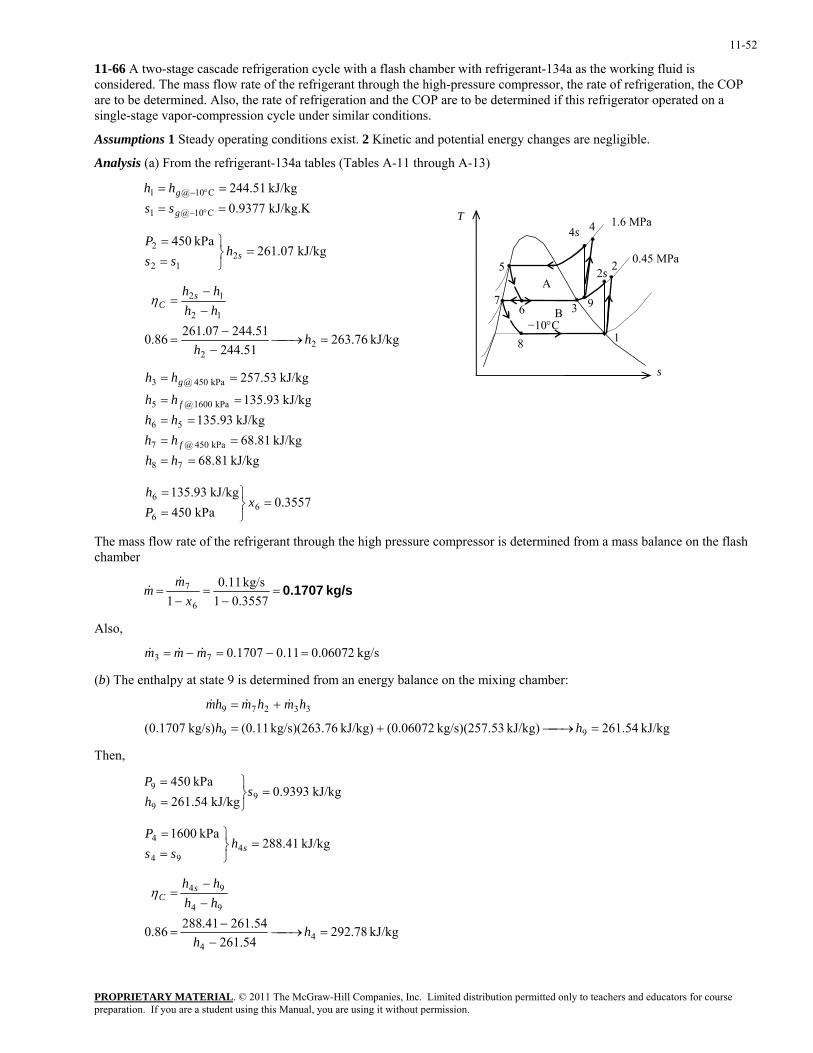
11-52
11-66 A two-stage cascade refrigeration cycle with a flash chamber with refrigerant-134a as the working fluid is considered. The mass flow rate of the refrigerant through the high-pressure compressor, the rate of refrigeration, the COP are to be determined. Also, the rate of refrigeration and the COP are to be determined if this refrigerator operated on a single-stage vapor-compression cycle under similar conditions.
Assumptions 1 Steady operating conditions exist. 2 Kinetic and potential energy changes are negligible.
Analysis (a) From the refrigerant-134a tables (Tables A-11 through A-13)
kJ/kg.K 9377.0kJ/kg 51.244
C10@1
C10@1
====
°−
°−
g
g
sshh
T
1
2 5
8
0.45 MPa
4s
9
2s
67
3 B−10°C
A
1.6 MPa 4
kJ/kg 07.261kPa 450
212
2 =⎭⎬⎫
==
shss
P
kJ/kg 76.263
51.24451.24407.26186.0 2
2
12
12
=⎯→⎯−
−=
−−
=
hh
hhhh s
Cη
s
kJ/kg 81.68kJ/kg 81.68
kJ/kg 93.135kJ/kg 93.135
kJ/kg 53.257
78
kPa 450 @7
56
kPa 1600 @5
kPa 450 @3
====
====
==
hhhhhhhh
hh
f
f
g
3557.0kPa 450
kJ/kg 93.1356
6
6 =⎭⎬⎫
==
xPh
The mass flow rate of the refrigerant through the high pressure compressor is determined from a mass balance on the flash chamber
kg/s 0.1707=−
=−
=0.35571
kg/s 11.01 6
7
xm
m&
&
Also,
kg/s 06072.011.01707.073 =−=−= mmm &&&
(b) The enthalpy at state 9 is determined from an energy balance on the mixing chamber:
kJ/kg 54.261kJ/kg) 53kg/s)(257. (0.06072kJ/kg) 76kg/s)(263. (0.11kg/s) 1707.0( 99
33279
=⎯→⎯+=
+=
hh
hmhmhm &&&
Then,
kJ/kg 9393.0kJ/kg 54.261
kPa 4509
9
9 =⎭⎬⎫
==
shP
kJ/kg 41.288kPa 1600
494
4 =⎭⎬⎫
==
shss
P
kJ/kg 78.292
54.26154.26141.28886.0 4
4
94
94
=⎯→⎯−
−=
−−
=
hh
hhhh s
Cη
PROPRIETARY MATERIALpreparation. If you are a student using this Manual, you are using it without permission.
. © 2011 The McGraw-Hill Companies, Inc. Limited distribution permitted only to teachers and educators for course
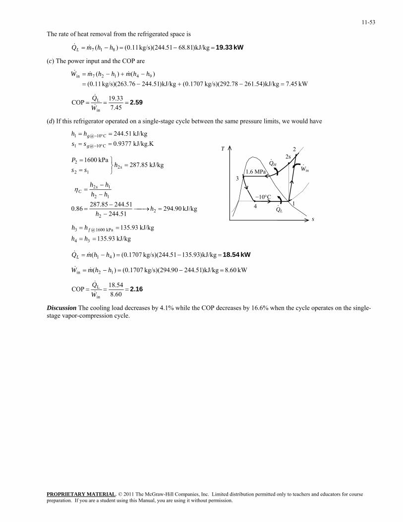
11-53
The rate of heat removal from the refrigerated space is
kW 19.33=−=−= kJ/kg)81.6851kg/s)(244. 11.0()( 817 hhmQL &&
(c) The power input and the COP are
kW 45.7kJ/kg)54.26178kg/s)(292. 1707.0(kJ/kg)51.24476kg/s)(263. 11.0()()( 94127in
=−+−=−+−= hhmhhmW &&&
2.59===45.733.19COP
in
L
WQ&
&
(d) If this refrigerator operated on a single-stage cycle between the same pressure limits, we would have
kJ/kg.K 9377.0kJ/kg 51.244
C10@1
C10@1
==
==
°−
°−
g
g
sshh
T
QH
QL
1
2s
3
4
1.6 MPa
2
Win·
−10°C
·
·
kJ/kg 85.287kPa 1600
212
2 =⎭⎬⎫
==
shss
P
kJ/kg 90.29451.244
51.24485.28786.0 22
12
12
=⎯→⎯−
−=
−−
=
hh
hhhh s
Cη
s
kJ/kg 93.135
kJ/kg 93.135
34
kPa 1600 @3
==
==
hh
hh f
kW 18.54=−=−= kJ/kg)93.13551kg/s)(244. 1707.0()( 41 hhmQL &&
kW 60.8kJ/kg)51.24490kg/s)(294. 1707.0()( 12in =−=−= hhmW &&
2.16===60.854.18COP
in
L
WQ&
&
Discussion The cooling load decreases by 4.1% while the COP decreases by 16.6% when the cycle operates on the single-stage vapor-compression cycle.
PROPRIETARY MATERIALpreparation. If you are a student using this Manual, you are using it without permission.
. © 2011 The McGraw-Hill Companies, Inc. Limited distribution permitted only to teachers and educators for course
11-54
Gas Refrigeration Cycles
11-67C The ideal gas refrigeration cycle is identical to the Brayton cycle, except it operates in the reversed direction.
11-68C In the ideal gas refrigeration cycle, the heat absorption and the heat rejection processes occur at constant pressure instead of at constant temperature.
11-69C The reversed Stirling cycle is identical to the Stirling cycle, except it operates in the reversed direction. Remembering that the Stirling cycle is a totally reversible cycle, the reversed Stirling cycle is also totally reversible, and thus its COP is
COPR,Stirling =−
11T TH L/
11-70C In aircraft cooling, the atmospheric air is compressed by a compressor, cooled by the surrounding air, and expanded in a turbine. The cool air leaving the turbine is then directly routed to the cabin.
11-71C No; because h = h(T) for ideal gases, and the temperature of air will not drop during a throttling (h1 = h2) process.
11-72C By regeneration.
PROPRIETARY MATERIALpreparation. If you are a student using this Manual, you are using it without permission.
. © 2011 The McGraw-Hill Companies, Inc. Limited distribution permitted only to teachers and educators for course
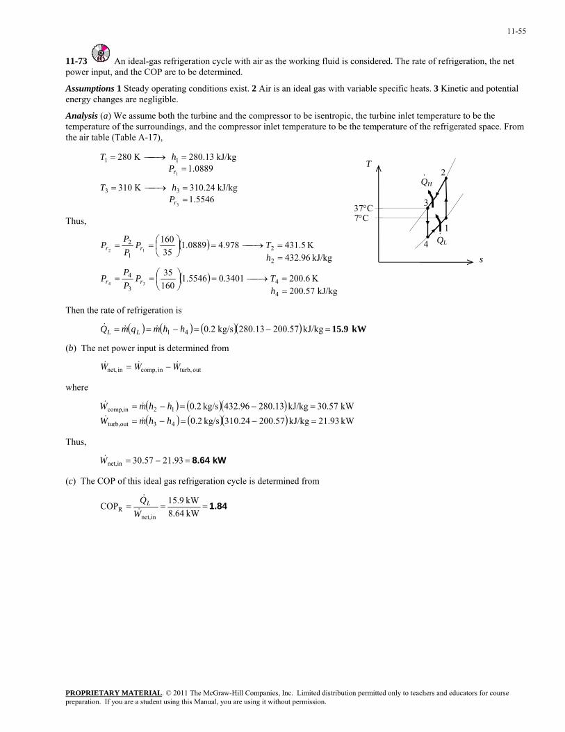
11-55
11-73 An ideal-gas refrigeration cycle with air as the working fluid is considered. The rate of refrigeration, the net power input, and the COP are to be determined.
Assumptions 1 Steady operating conditions exist. 2 Air is an ideal gas with variable specific heats. 3 Kinetic and potential energy changes are negligible.
Analysis (a) We assume both the turbine and the compressor to be isentropic, the turbine inlet temperature to be the temperature of the surroundings, and the compressor inlet temperature to be the temperature of the refrigerated space. From the air table (Table A-17),
5546.1kJ/kg 24.310K 310
0889.1kJ/kg 13.280K 280
3
1
33
11
==⎯→⎯=
==⎯→⎯=
r
r
PhT
PhT
T
1
2 QH
3
4 QL·
·
37°C 7°C Thus,
( )
( )kJ/kg 57.200
K 6.2003401.05546.116035
kJ/kg 96.432K 5.431978.40889.1
35160
4
43
4
2
21
2
34
12
==⎯→⎯=⎟
⎠⎞
⎜⎝⎛==
==⎯→⎯=⎟
⎠⎞
⎜⎝⎛==
hTP
PP
P
hTP
PP
P
rr
rr
s
Then the rate of refrigeration is
( ) ( ) ( )( ) kW 15.9=−=−== kJ/kg 200.57280.13kg/s 0.241 hhmqmQ LL &&&
(b) The net power input is determined from
& & &W W Wnet, in comp, in turb, out= −
where
( ) ( )( )( ) ( )( ) kW .9321kJ/kg 200.57310.24kg/s 0.2
kW .5730kJ/kg 280.13432.96kg/s 0.2
43outturb,
12incomp,
=−=−=
=−=−=
hhmWhhmW
&&
&&
Thus,
kW 8.64=−= 93.2157.30innet,W&
(c) The COP of this ideal gas refrigeration cycle is determined from
1.84===kW 8.64kW 15.9COP
innet,R W
QL&
&
PROPRIETARY MATERIALpreparation. If you are a student using this Manual, you are using it without permission.
. © 2011 The McGraw-Hill Companies, Inc. Limited distribution permitted only to teachers and educators for course
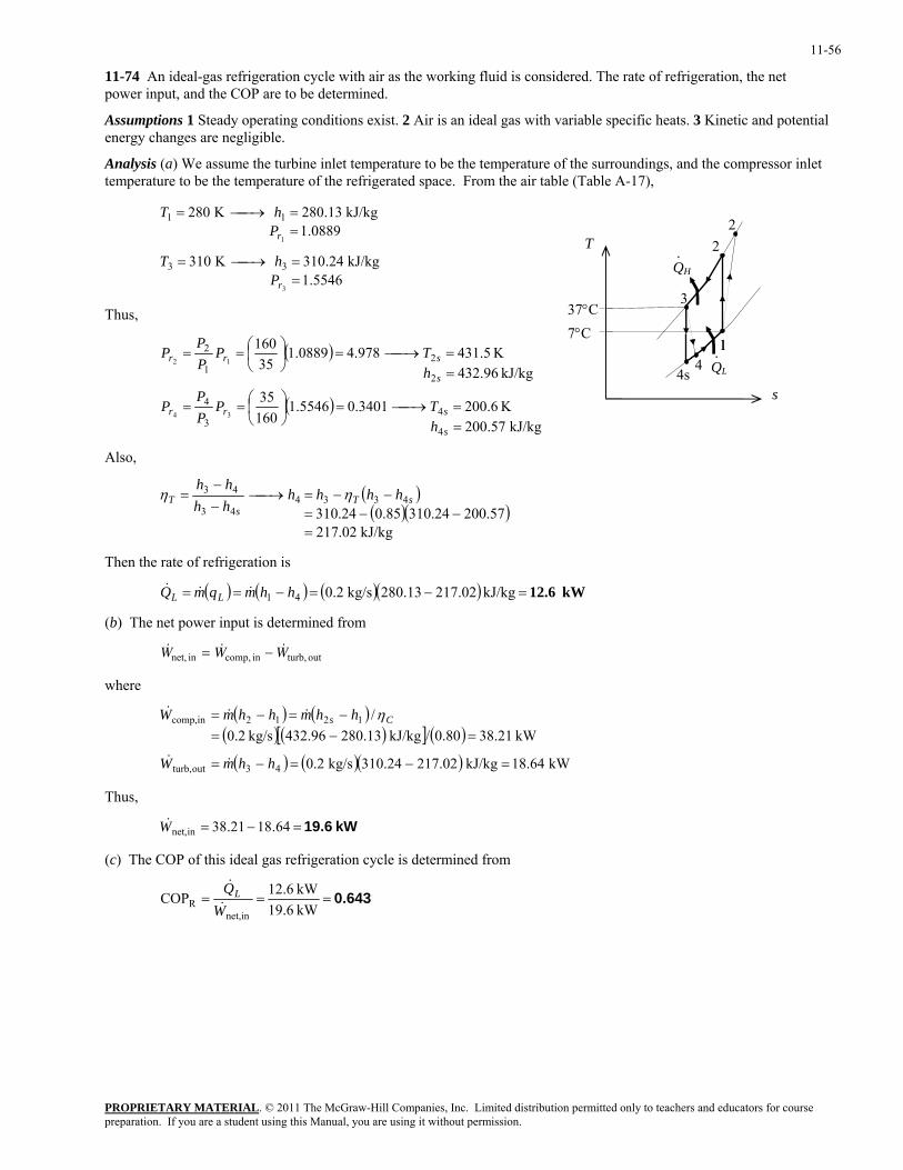
11-56
11-74 An ideal-gas refrigeration cycle with air as the working fluid is considered. The rate of refrigeration, the net power input, and the COP are to be determined.
Assumptions 1 Steady operating conditions exist. 2 Air is an ideal gas with variable specific heats. 3 Kinetic and potential energy changes are negligible.
Analysis (a) We assume the turbine inlet temperature to be the temperature of the surroundings, and the compressor inlet temperature to be the temperature of the refrigerated space. From the air table (Table A-17),
5546.1kJ/kg 24.310K 310
0889.1kJ/kg 13.280K 280
3
1
33
11
==⎯→⎯=
==⎯→⎯=
r
r
PhT
PhT
1
2QH
3
4s QL·
2
4 1
·T
37°CThus, 7°C
( )
( )kJ/kg 57.200
K 6.2003401.05546.116035
kJ/kg 96.432K 5.431978.40889.1
35160
4
43
4
2
21
2
34
12
==⎯→⎯=⎟
⎠⎞
⎜⎝⎛==
==⎯→⎯=⎟
⎠⎞
⎜⎝⎛==
s
srr
s
srr
hTP
PP
P
hTP
PP
P
s
Also,
( )( )(
kJ/kg 02.21757.20024.31085.024.310
433443
43
=−−=
−−=⎯→⎯−−
= sTs
T hhhhhhhh
ηη)
Then the rate of refrigeration is
( ) ( ) ( )( ) kW 12.6=−=−== kJ/kg 217.02280.13kg/s 0.241 hhmqmQ LL &&&
(b) The net power input is determined from
& & &W W Wnet, in comp, in turb, out= −
where
( ) ( )
( ) ( )[ ] ( )( ) ( )( ) kW 18.64kJ/kg 217.02310.24kg/s 0.2
kW .21380.80/kJ/kg 280.13432.96kg/s 0.2/
43outturb,
1212incomp,
=−=−=
=−=−=−=
hhmW
hhmhhmW Cs
&&
&&& η
Thus,
kW 19.6=−= 64.1821.38innet,W&
(c) The COP of this ideal gas refrigeration cycle is determined from
0.643===kW 19.6kW 12.6COP
innet,R W
QL&
&
PROPRIETARY MATERIALpreparation. If you are a student using this Manual, you are using it without permission.
. © 2011 The McGraw-Hill Companies, Inc. Limited distribution permitted only to teachers and educators for course
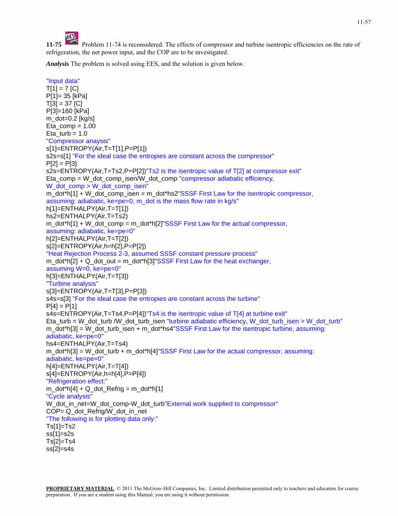
11-57
11-75 Problem 11-74 is reconsidered. The effects of compressor and turbine isentropic efficiencies on the rate of refrigeration, the net power input, and the COP are to be investigated.
Analysis The problem is solved using EES, and the solution is given below.
"Input data" T[1] = 7 [C] P[1]= 35 [kPa] T[3] = 37 [C] P[3]=160 [kPa] m_dot=0.2 [kg/s] Eta_comp = 1.00 Eta_turb = 1.0 "Compressor anaysis" s[1]=ENTROPY(Air,T=T[1],P=P[1]) s2s=s[1] "For the ideal case the entropies are constant across the compressor" P[2] = P[3] s2s=ENTROPY(Air,T=Ts2,P=P[2])"Ts2 is the isentropic value of T[2] at compressor exit" Eta_comp = W_dot_comp_isen/W_dot_comp "compressor adiabatic efficiency, W_dot_comp > W_dot_comp_isen" m_dot*h[1] + W_dot_comp_isen = m_dot*hs2"SSSF First Law for the isentropic compressor, assuming: adiabatic, ke=pe=0, m_dot is the mass flow rate in kg/s" h[1]=ENTHALPY(Air,T=T[1]) hs2=ENTHALPY(Air,T=Ts2) m_dot*h[1] + W_dot_comp = m_dot*h[2]"SSSF First Law for the actual compressor, assuming: adiabatic, ke=pe=0" h[2]=ENTHALPY(Air,T=T[2]) s[2]=ENTROPY(Air,h=h[2],P=P[2]) "Heat Rejection Process 2-3, assumed SSSF constant pressure process" m_dot*h[2] + Q_dot_out = m_dot*h[3]"SSSF First Law for the heat exchanger, assuming W=0, ke=pe=0" h[3]=ENTHALPY(Air,T=T[3]) "Turbine analysis" s[3]=ENTROPY(Air,T=T[3],P=P[3]) s4s=s[3] "For the ideal case the entropies are constant across the turbine" P[4] = P[1] s4s=ENTROPY(Air,T=Ts4,P=P[4])"Ts4 is the isentropic value of T[4] at turbine exit" Eta_turb = W_dot_turb /W_dot_turb_isen "turbine adiabatic efficiency, W_dot_turb_isen > W_dot_turb" m_dot*h[3] = W_dot_turb_isen + m_dot*hs4"SSSF First Law for the isentropic turbine, assuming: adiabatic, ke=pe=0" hs4=ENTHALPY(Air,T=Ts4) m_dot*h[3] = W_dot_turb + m_dot*h[4]"SSSF First Law for the actual compressor, assuming: adiabatic, ke=pe=0" h[4]=ENTHALPY(Air,T=T[4]) s[4]=ENTROPY(Air,h=h[4],P=P[4]) "Refrigeration effect:" m_dot*h[4] + Q_dot_Refrig = m_dot*h[1] "Cycle analysis" W_dot_in_net=W_dot_comp-W_dot_turb"External work supplied to compressor" COP= Q_dot_Refrig/W_dot_in_net "The following is for plotting data only:" Ts[1]=Ts2 ss[1]=s2s Ts[2]=Ts4 ss[2]=s4s
PROPRIETARY MATERIALpreparation. If you are a student using this Manual, you are using it without permission.
. © 2011 The McGraw-Hill Companies, Inc. Limited distribution permitted only to teachers and educators for course
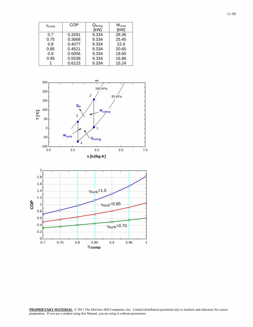
11-58
ηcomp COP QRefrig
[kW] Winnet [kW]
0.7 0.75 0.8 0.85 0.9 0.95
1
0.3291 0.3668 0.4077 0.4521 0.5006 0.5538 0.6123
9.334 9.334 9.334 9.334 9.334 9.334 9.334
28.36 25.45 22.9
20.65 18.65 16.86 15.24
5.0 5.5 6.0 6.5 7.0-100
-50
0
50
100
150
200
250
s [kJ/kg-K]
T [°
C]
160 kPa
35 kPa
Air
1
2
3
4
Wcom p
Wturb Qrefrig
QH
0.7 0.75 0.8 0.85 0.9 0.95 10
0.2
0.4
0.6
0.8
1
1.2
1.4
1.6
1.8
2
ηcomp
COP
ηturb=1.0
ηturb=0.85
ηturb=0.70
PROPRIETARY MATERIALpreparation. If you are a student using this Manual, you are using it without permission.
. © 2011 The McGraw-Hill Companies, Inc. Limited distribution permitted only to teachers and educators for course
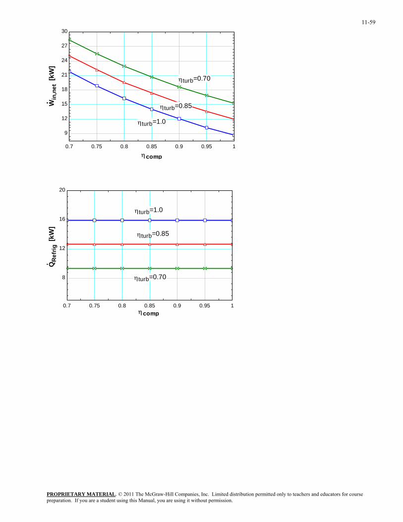
11-59
0.7 0.75 0.8 0.85 0.9 0.95 1
9
12
15
18
21
24
27
30
ηcomp
Win
,net
[kW
]
ηturb=1.0
ηturb=0.85
ηturb=0.70
0.7 0.75 0.8 0.85 0.9 0.95 1
8
12
16
20
ηcomp
QR
efrig
[kW
]
ηturb=0.85
ηturb=1.0
ηturb=0.70
PROPRIETARY MATERIALpreparation. If you are a student using this Manual, you are using it without permission.
. © 2011 The McGraw-Hill Companies, Inc. Limited distribution permitted only to teachers and educators for course
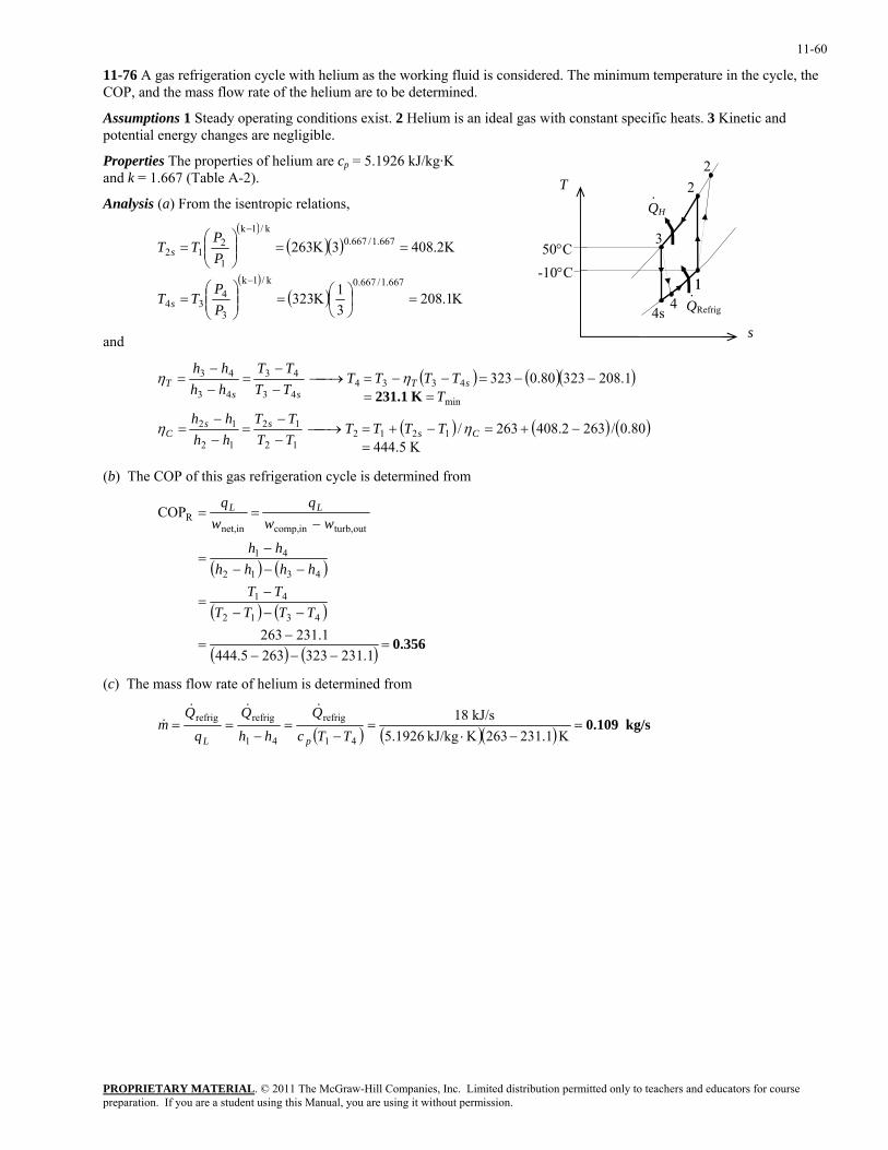
11-60
11-76 A gas refrigeration cycle with helium as the working fluid is considered. The minimum temperature in the cycle, the COP, and the mass flow rate of the helium are to be determined.
Assumptions 1 Steady operating conditions exist. 2 Helium is an ideal gas with constant specific heats. 3 Kinetic and potential energy changes are negligible.
Properties The properties of helium are cp = 5.1926 kJ/kg·K and k = 1.667 (Table A-2).
1
2QH
3
4s QRefrig·
2
4 1
·T
Analysis (a) From the isentropic relations,
( )( )( )
( )( ) K1.208
31K323
K2.4083K263
667.1/667.0k/1k
3
434
667.1/667.0k/1k
1
212
=⎟⎠⎞
⎜⎝⎛=⎟⎟
⎠
⎞⎜⎜⎝
⎛=
==⎟⎟⎠
⎞⎜⎜⎝
⎛=
−
−
PP
TT
PP
TT
s
s
50°C
-10°C
s and
( ) ( )( )
( ) ( ) (K 5.444
80.0/2632.408263/
1.20832380.0323
121212
12
12
12
min
433443
43
43
43
=−+=−+=⎯→⎯
−−
=−−
=
==−−=−−=⎯→⎯
−−
=−−
=
Csss
C
sTss
T
TTTTTTTT
hhhh
TTTTT
TTTT
hhhh
ηη
ηηK 231.1
)
(b) The COP of this gas refrigeration cycle is determined from
( ) ( )
( ) ( )
( ) ( ) 0.356=−−−
−=
−−−−
=
−−−−
=
−==
1.2313232635.4441.231263
COP
4312
41
4312
41
outturb,incomp,innet,R
TTTTTT
hhhhhh
wwq
wq LL
(c) The mass flow rate of helium is determined from
( ) ( )( ) kg/s 0.109=−⋅
=−
=−
==K 231.1263KkJ/kg 5.1926
kJ/s 18
41
refrig
41
refrigrefrig
TTcQ
hhQ
mpL
&&&&
PROPRIETARY MATERIALpreparation. If you are a student using this Manual, you are using it without permission.
. © 2011 The McGraw-Hill Companies, Inc. Limited distribution permitted only to teachers and educators for course
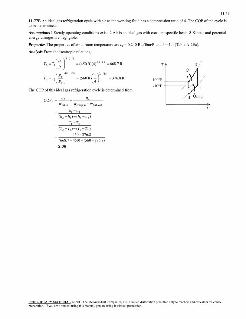
11-61
11-77E An ideal gas refrigeration cycle with air as the working fluid has a compression ratio of 4. The COP of the cycle is to be determined.
Assumptions 1 Steady operating conditions exist. 2 Air is an ideal gas with constant specific heats. 3 Kinetic and potential energy changes are negligible.
Properties The properties of air at room temperature are cp = 0.240 Btu/lbm·R and k = 1.4 (Table A-2Ea).
Analysis From the isentropic relations,
R 8.37641R) 560(
R 7.668R)(4) 450(
4.1/4.0/)1(
3
434
4.1/4.0/)1(
1
212
=⎟⎠⎞
⎜⎝⎛=⎟⎟
⎠
⎞⎜⎜⎝
⎛=
==⎟⎟⎠
⎞⎜⎜⎝
⎛=
−
−
kk
kk
PP
TT
PP
TT
1
2 QH
3
4 QRefrig·
·
s
T
100°F-10°F
The COP of this ideal gas refrigeration cycle is determined from
2.06=−−−
−=
−−−−
=
−−−−
=
−==
)8.376560()4507.668(8.376450)()(
)()(
COP
4312
41
4312
41
outturb,incomp,innet,R
TTTTTT
hhhhhh
wwq
wq LL
PROPRIETARY MATERIALpreparation. If you are a student using this Manual, you are using it without permission.
. © 2011 The McGraw-Hill Companies, Inc. Limited distribution permitted only to teachers and educators for course
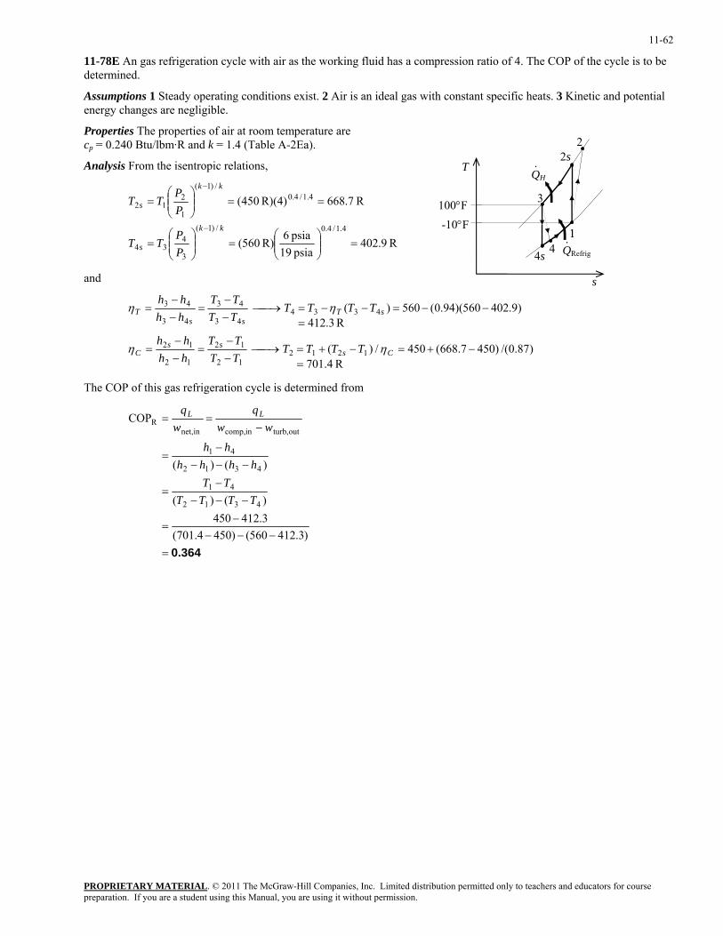
11-62
11-78E An gas refrigeration cycle with air as the working fluid has a compression ratio of 4. The COP of the cycle is to be determined.
Assumptions 1 Steady operating conditions exist. 2 Air is an ideal gas with constant specific heats. 3 Kinetic and potential energy changes are negligible.
Properties The properties of air at room temperature are cp = 0.240 Btu/lbm·R and k = 1.4 (Table A-2Ea).
T
1
2s QH
3
4s QRefrig·
2
4 1
·
100°F
s
Analysis From the isentropic relations,
R 9.402psia 19psia 6
R) 560(
R 7.668R)(4) 450(
4.1/4.0/)1(
3
434
4.1/4.0/)1(
1
212
=⎟⎟⎠
⎞⎜⎜⎝
⎛=⎟⎟
⎠
⎞⎜⎜⎝
⎛=
==⎟⎟⎠
⎞⎜⎜⎝
⎛=
−
−
kk
s
kk
s
PP
TT
PP
TT
-10°F
and
R 1.470)87.0/()4507.668(450/)(
R 3.412)9.402560)(94.0(560)(
121212
12
12
12
433443
43
43
43
=−+=−+=⎯→⎯
−−
=−−
=
=−−=−−=⎯→⎯
−−
=−−
=
Csss
C
sTss
T
TTTTTTTT
hhhh
TTTTTTTT
hhhh
ηη
ηη
The COP of this gas refrigeration cycle is determined from
0.364=−−−
−=
−−−−
=
−−−−
=
−==
)3.412560()4504.701(3.412450)()(
)()(
COP
4312
41
4312
41
outturb,incomp,innet,R
TTTTTT
hhhhhh
wwq
wq LL
PROPRIETARY MATERIALpreparation. If you are a student using this Manual, you are using it without permission.
. © 2011 The McGraw-Hill Companies, Inc. Limited distribution permitted only to teachers and educators for course
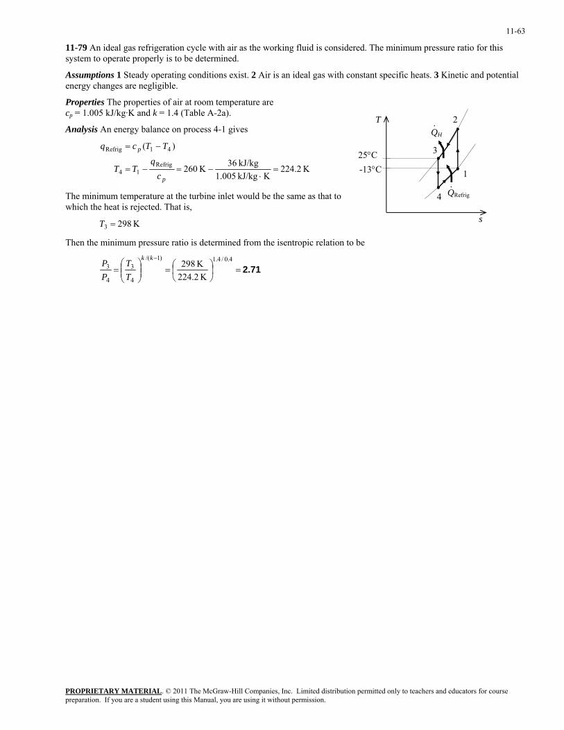
11-63
11-79 An ideal gas refrigeration cycle with air as the working fluid is considered. The minimum pressure ratio for this system to operate properly is to be determined.
Assumptions 1 Steady operating conditions exist. 2 Air is an ideal gas with constant specific heats. 3 Kinetic and potential energy changes are negligible.
Properties The properties of air at room temperature are cp = 1.005 kJ/kg·K and k = 1.4 (Table A-2a).
1
2QH
3
4 QRefrig·
·
s
TAnalysis An energy balance on process 4-1 gives
K 2.224KkJ/kg 1.005
kJ/kg 36K 260
)(
Refrig14
41Refrig
=⋅
−=−=
−=
p
p
cq
TT
TTcq
25°C -13°C
The minimum temperature at the turbine inlet would be the same as that to which the heat is rejected. That is,
K 2983 =T
Then the minimum pressure ratio is determined from the isentropic relation to be
2.71=⎟⎠⎞
⎜⎝⎛=⎟⎟
⎠
⎞⎜⎜⎝
⎛=
− 4.0/4.1)1/(
4
3
4
3
K 224.2K 298
kk
TT
PP
PROPRIETARY MATERIALpreparation. If you are a student using this Manual, you are using it without permission.
. © 2011 The McGraw-Hill Companies, Inc. Limited distribution permitted only to teachers and educators for course
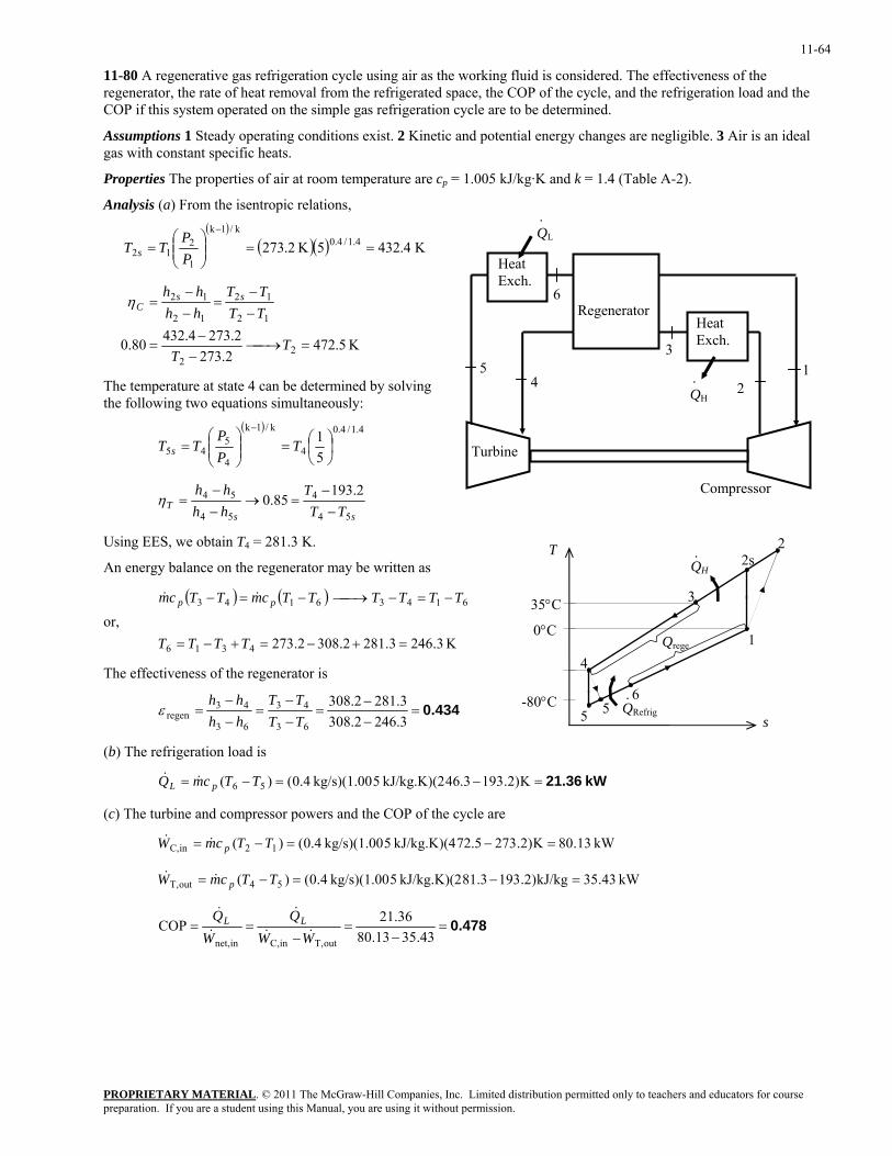
11-64
11-80 A regenerative gas refrigeration cycle using air as the working fluid is considered. The effectiveness of the regenerator, the rate of heat removal from the refrigerated space, the COP of the cycle, and the refrigeration load and the COP if this system operated on the simple gas refrigeration cycle are to be determined.
Assumptions 1 Steady operating conditions exist. 2 Kinetic and potential energy changes are negligible. 3 Air is an ideal gas with constant specific heats.
Properties The properties of air at room temperature are cp = 1.005 kJ/kg·K and k = 1.4 (Table A-2).
Analysis (a) From the isentropic relations,
.
3
45
6
QH
Compressor
12
QL
Turbine
Heat Exch.
Heat Exch.
Regenerator
.
( )
( )( ) K 4.4325K 2.273 4.1/4.0k/1k
1
212 ==⎟⎟
⎠
⎞⎜⎜⎝
⎛=
−
PP
TT s
K 5.472
2.2732.2734.43280.0 2
2
12
12
12
12
=⎯→⎯−
−=
−−
=−−
=
TT
TTTT
hhhh ss
Cη
The temperature at state 4 can be determined by solving the following two equations simultaneously:
( ) 4.1/4.0
4
k/1k
4
545 5
1⎟⎠⎞
⎜⎝⎛=⎟⎟
⎠
⎞⎜⎜⎝
⎛=
−
TPP
TT s
ssT TT
Thhhh
54
4
54
54 2.19385.0
−−
=→−−
=η
Using EES, we obtain T4 = 281.3 K.
s
1
3
56
4
2sQH·
QRefrig·
Qrege
5
2TAn energy balance on the regenerator may be written as
or, ( ) ( )
K 3.2463.2812.3082.2734316
61436143
=+−=+−=
−=−⎯→⎯−=−
TTTT
TTTTTTcmTTcm pp && 35°C
0°C
The effectiveness of the regenerator is
0.434=−−
=−−
=−−
=3.2462.3083.2812.308
63
43
63
43regen TT
TThhhh
ε -80°C
(b) The refrigeration load is
kW 21.36=−=−= K)2.19346.3kJ/kg.K)(2 5kg/s)(1.00 4.0()( 56 TTcmQ pL &&
(c) The turbine and compressor powers and the COP of the cycle are
kW 13.80K)2.27372.5kJ/kg.K)(4 5kg/s)(1.00 4.0()( 12inC, =−=−= TTcmW p&&
kW 43.35kJ/kg)2.19381.3kJ/kg.K)(2 5kg/s)(1.00 4.0()( 54outT, =−=−= TTcmW p&&
0.478=−
=−
==43.3513.80
36.21COPoutT,inC,innet, WW
QW
Q LL&&
&
&
&
PROPRIETARY MATERIALpreparation. If you are a student using this Manual, you are using it without permission.
. © 2011 The McGraw-Hill Companies, Inc. Limited distribution permitted only to teachers and educators for course
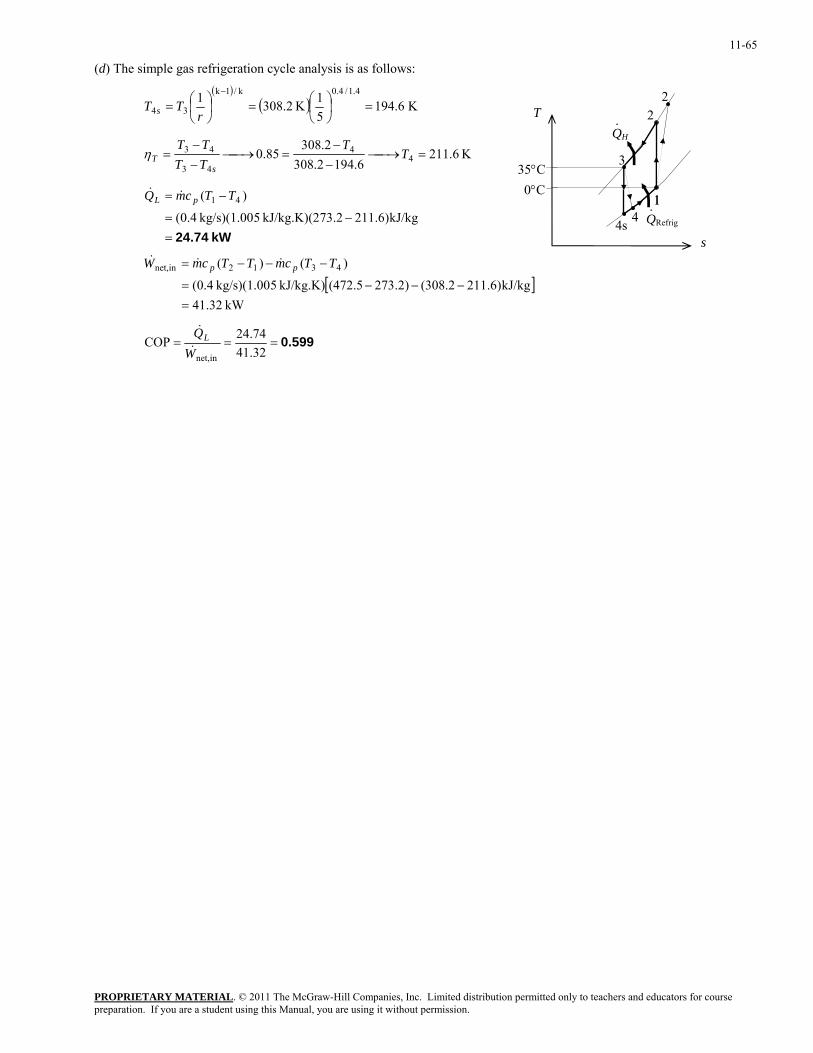
11-65
(d) The simple gas refrigeration cycle analysis is as follows: ( )
( ) K 6.19451K 2.3081 4.1/4.0k/1k
34 =⎟⎠⎞
⎜⎝⎛=⎟
⎠⎞
⎜⎝⎛=
−
rTT s
1
2QH
3
4s QRefrig·
2
4 1
·T
K 6.2116.1942.308
2.30885.0 4
4
43
43 =⎯→⎯−
−=⎯→⎯
−−
= TT
TTTT
sTη
35°C 0°C
kW 24.74=−=
−=
kJ/kg)6.21173.2kJ/kg.K)(2 5kg/s)(1.00 4.0(
)( 41 TTcmQ pL &&
s
[ ]kW 32.41
kJ/kg)6.211(308.2)2.273(472.5kJ/kg.K) 5kg/s)(1.00 4.0(
)()( 4312innet,
=−−−=
−−−= TTcmTTcmW pp &&&
0.599===32.4174.24COP
innet,WQL&
&
PROPRIETARY MATERIALpreparation. If you are a student using this Manual, you are using it without permission.
. © 2011 The McGraw-Hill Companies, Inc. Limited distribution permitted only to teachers and educators for course
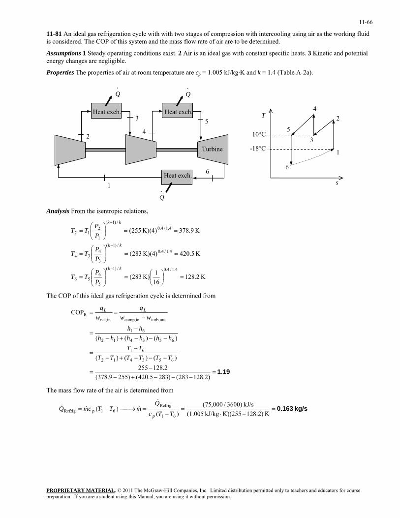
11-66
11-81 An ideal gas refrigeration cycle with with two stages of compression with intercooling using air as the working fluid is considered. The COP of this system and the mass flow rate of air are to be determined.
Assumptions 1 Steady operating conditions exist. 2 Air is an ideal gas with constant specific heats. 3 Kinetic and potential energy changes are negligible.
Properties The properties of air at room temperature are cp = 1.005 kJ/kg·K and k = 1.4 (Table A-2a).
3
4 5
6
. Q
1
2
Turbine
Q .
Heat exch.
xch.Heat e
Heat exch.
. Q
10°C
4
3
6
5
2
1
s
T
-18°C
Analysis From the isentropic relations,
K 2.128161K) 283(
K 5.420K)(4) 283(
K 9.378K)(4) 255(
4.1/4.0/)1(
5
656
4.1/4.0/)1(
3
434
4.1/4.0/)1(
1
212
=⎟⎠⎞
⎜⎝⎛=⎟⎟
⎠
⎞⎜⎜⎝
⎛=
==⎟⎟⎠
⎞⎜⎜⎝
⎛=
==⎟⎟⎠
⎞⎜⎜⎝
⎛=
−
−
−
kk
kk
kk
PP
TT
PP
TT
PP
TT
The COP of this ideal gas refrigeration cycle is determined from
1.19=−−−+−
−=
−−−+−−
=
−−−+−−
=
−==
)2.128283()2835.420()2559.378(2.128255
)()()(
)()()(
COP
653412
61
653412
61
outturb,incomp,innet,R
TTTTTTTT
hhhhhhhh
wwq
wq LL
The mass flow rate of the air is determined from
kg/s 0.163=−⋅
=−
=⎯→⎯−=K )2.128K)(255kJ/kg (1.005
kJ/s )3600/000,75()(
)(61
Refrig61Refrig TTc
QmTTcmQ
pp
&&&&
PROPRIETARY MATERIALpreparation. If you are a student using this Manual, you are using it without permission.
. © 2011 The McGraw-Hill Companies, Inc. Limited distribution permitted only to teachers and educators for course
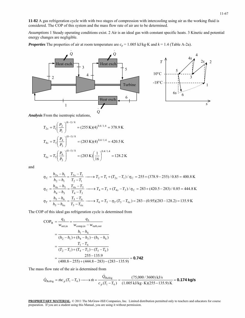
11-67
11-82 A gas refrigeration cycle with with two stages of compression with intercooling using air as the working fluid is considered. The COP of this system and the mass flow rate of air are to be determined.
Assumptions 1 Steady operating conditions exist. 2 Air is an ideal gas with constant specific heats. 3 Kinetic and potential energy changes are negligible.
Properties The properties of air at room temperature are cp = 1.005 kJ/kg·K and k = 1.4 (Table A-2a).
PROPRIETARY MATERIAL. © 2011 The McGraw-Hill Companies, Inc. Limited distribution permitted only to teachers and educators for course
Analysis From the isentropic relations,
3
4 5
6
. Q
1
2
Turbine
Q .
Heat exch.
xch.Heat e
Heat exch.
. Q
10°C
6s
2T
1
3
4
6
5
4s 2s
-18°C
s
K 2.128161K) 283(
K 5.420K)(4) 283(
K 9.378K)(4) 255(
4.1/4.0/)1(
5
656
4.1/4.0/)1(
3
434
4.1/4.0/)1(
1
212
=⎟⎠⎞
⎜⎝⎛=⎟⎟
⎠
⎞⎜⎜⎝
⎛=
==⎟⎟⎠
⎞⎜⎜⎝
⎛=
==⎟⎟⎠
⎞⎜⎜⎝
⎛=
−
−
−
kk
s
kk
s
kk
s
PP
TT
PP
TT
PP
TT
and
K 9.135)2.128283)(95.0(283)(
K 8.44485.0/)2835.420(283/)(
K 8.40085.0/)2559.378(255/)(
655665
65
65
65
343434
34
34
34
121212
12
12
12
=−−=−−=⎯→⎯−−
=−−
=
=−+=−+=⎯→⎯−−
=−−
=
=−+=−+=⎯→⎯−−
=−−
=
sTss
T
Csss
C
Csss
C
TTTTTTTT
hhhh
TTTTTTTT
hhhh
TTTTTTTT
hhhh
ηη
ηη
ηη
The COP of this ideal gas refrigeration cycle is determined from
0.742=−−−+−
−=
−−−+−−
=
−−−+−−
=
−==
)9.135283()2838.444()2558.400(9.135255
)()()(
)()()(
COP
653412
61
653412
61
outturb,incomp,innet,R
TTTTTTTT
hhhhhhhh
wwq
wq LL
The mass flow rate of the air is determined from
kg/s 0.174=−⋅
=−
=⎯→⎯−=K )9.135K)(255kJ/kg (1.005
kJ/s )3600/000,75()(
)(61
Refrig61Refrig TTc
QmTTcmQ
pp
&&&&
preparation. If you are a student using this Manual, you are using it without permission.
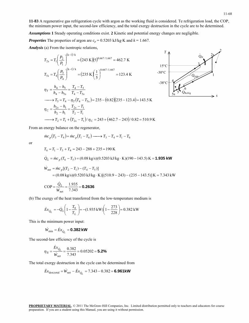
11-68
11-83 A regenerative gas refrigeration cycle with argon as the working fluid is considered. Te refrigeration load, the COP, the minimum power input, the second-law efficiency, and the total exergy destruction in the cycle are to be determined.
Assumptions 1 Steady operating conditions exist. 2 Kinetic and potential energy changes are negligible.
Properties The properties of argon are cp = 0.5203 kJ/kg·K and k = 1.667.
Analysis (a) From the isentropic relations,
PROPRIETARY MATERIAL. © 2011 The McGraw-Hill Companies, Inc. Limited distribution permitted only to teachers and educators for course
( )( )( )
( )( ) K 4.123
51K 235
K 7.4625K 243
667.1/667.0k/1k
4
545
667.1/667.0k/1k
1
212
=⎟⎠⎞
⎜⎝⎛=⎟⎟
⎠
⎞⎜⎜⎝
⎛=
==⎟⎟⎠
⎞⎜⎜⎝
⎛=
−
−
PP
TT
PP
TT
s
s
( ) ( )( )
( ) ( ) K 9.51082.0/2437.462243/
K 5.1434.12323582.0235
1212
12
12
12
12
5445
54
54
54
54
=−+=−+=⎯→⎯
−−
=−−
=
=−−=−−=⎯→⎯
−−
=−−
=
Cs
ssC
sT
ssT
TTTT
TTTT
hhhh
TTTT
TTTT
hhhh
η
η
η
η
s
T
1
3
-30°C
-38°C
5s 6
4
2sQH·
QRefrig·
Qrege
5
2
15°C
From an energy balance on the regenerator,
or
( ) ( )
K 1902352882434316
61436143
=+−=+−=
−=−⎯→⎯−=−
TTTT
TTTTTTcmTTcm pp &&
kW 1.935=−⋅=−= K )5.143190)(KkJ/kg 5203.0(kg/s) 08.0()( 56 TTcmQ pL &&
kW 343.7K )]5.143235()2439.510)[(KkJ/kg 5203.0(kg/s) 08.0(
)]()[( 5412
=−−−⋅=
−−−= TTTTcmW pnet &&
0.2636===343.7935.1COP
netWQL&
&
(b) The exergy of the heat transferred from the low-temperature medium is
kW 382.02282731kW) 935.1(1 0 =⎟
⎠⎞
⎜⎝⎛ −−=⎟⎟
⎠
⎞⎜⎜⎝
⎛−−=
LLQ T
TQxE
L
&&&
This is the minimum power input:
kW 0.382==LQxEW &
&&min
The second-law efficiency of the cycle is
5.2%==== 0.05202343.7382.0
netII W
xELQ
&
&&
η
The total exergy destruction in the cycle can be determined from
6.961kW=−=−= 382.0343.7nettotaldest, LQxEWxE &&&&
preparation. If you are a student using this Manual, you are using it without permission.
11-69
Absorption Refrigeration Systems
11-84C In absorption refrigeration, water can be used as the refrigerant in air conditioning applications since the temperature of water never needs to fall below the freezing point.
11-85C Absorption refrigeration is the kind of refrigeration that involves the absorption of the refrigerant during part of the cycle. In absorption refrigeration cycles, the refrigerant is compressed in the liquid phase instead of in the vapor form.
11-86C The main advantage of absorption refrigeration is its being economical in the presence of an inexpensive heat source. Its disadvantages include being expensive, complex, and requiring an external heat source.
11-87C The fluid in the absorber is cooled to maximize the refrigerant content of the liquid; the fluid in the generator is heated to maximize the refrigerant content of the vapor.
11-88C The coefficient of performance of absorption refrigeration systems is defined as
geninpump,gen
R inputrequiredoutputdesiredCOP
WQQ LL ≅
+==
11-89C The rectifier separates the water from NH3 and returns it to the generator. The regenerator transfers some heat from the water-rich solution leaving the generator to the NH3-rich solution leaving the pump.
11-90 The COP of an absorption refrigeration system that operates at specified conditions is given. It is to be determined whether the given COP value is possible.
Analysis The maximum COP that this refrigeration system can have is
97.2273292
273K 368K 29211COP
0
0maxR, =⎟
⎠⎞
⎜⎝⎛
−⎟⎠⎞
⎜⎝⎛ −=⎟⎟
⎠
⎞⎜⎜⎝
⎛−⎟⎟
⎠
⎞⎜⎜⎝
⎛−=
L
L
s TTT
TT
which is smaller than 3.1. Thus the claim is not possible.
PROPRIETARY MATERIALpreparation. If you are a student using this Manual, you are using it without permission.
. © 2011 The McGraw-Hill Companies, Inc. Limited distribution permitted only to teachers and educators for course
11-70
11-91 The conditions at which an absorption refrigeration system operates are specified. The maximum COP this absorption refrigeration system can have is to be determined.
Analysis The maximum COP that this refrigeration system can have is
2.64=⎟⎠⎞
⎜⎝⎛
−⎟⎠⎞
⎜⎝⎛ −=⎟⎟
⎠
⎞⎜⎜⎝
⎛−⎟⎟
⎠
⎞⎜⎜⎝
⎛−=
273298273
K 393K 29811COP
0
0maxR,
L
L
s TTT
TT
11-92 The conditions at which an absorption refrigeration system operates are specified. The maximum rate at which this system can remove heat from the refrigerated space is to be determined.
Analysis The maximum COP that this refrigeration system can have is
151243298
243K 403K 29811COP
0
0maxR, .
TTT
TT
L
L
s=⎟
⎠⎞
⎜⎝⎛
−⎟⎟⎠
⎞⎜⎜⎝
⎛−=⎟⎟
⎠
⎞⎜⎜⎝
⎛−⎟⎟
⎠
⎞⎜⎜⎝
⎛−=
Thus,
( )( ) kJ/h 105.75 5×=×== kJ/h 10515.1COP 5genmaxR,maxL, QQ &&
PROPRIETARY MATERIALpreparation. If you are a student using this Manual, you are using it without permission.
. © 2011 The McGraw-Hill Companies, Inc. Limited distribution permitted only to teachers and educators for course
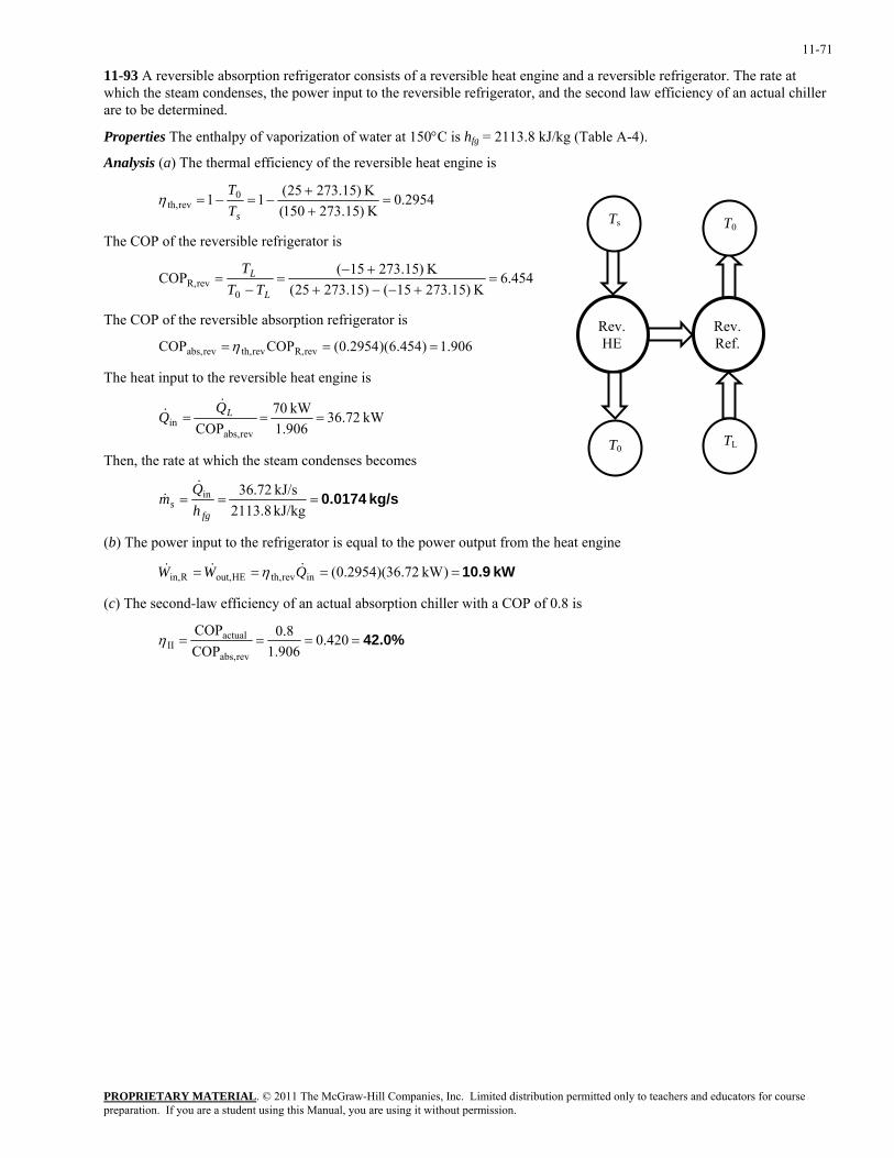
11-71
11-93 A reversible absorption refrigerator consists of a reversible heat engine and a reversible refrigerator. The rate at which the steam condenses, the power input to the reversible refrigerator, and the second law efficiency of an actual chiller are to be determined.
Properties The enthalpy of vaporization of water at 150°C is hfg = 2113.8 kJ/kg (Table A-4).
Analysis (a) The thermal efficiency of the reversible heat engine is
2954.0K )15.273150(K )15.27325(11 0
revth, =++
−=−=sT
Tη
PROPRIETARY MATERIAL. © 2011 The McGraw-Hill Companies, Inc. Limited distribution permitted only to teachers and educators for course
The COP of the reversible refrigerator is
454.6K )15.27315()15.27325(
K )15.27315(COP0
revR, =+−−+
+−=
−=
L
L
TTT
Rev.Ref.
T0
TL
Rev. HE
Ts
T0
The COP of the reversible absorption refrigerator is
906.1)454.6)(2954.0(COPCOP revR,revth,revabs, ===η
The heat input to the reversible heat engine is
kW 72.361.906
kW 70COP revabs,
in === LQQ
&&
Then, the rate at which the steam condenses becomes
kg/s 0.0174===kJ/kg 2113.8kJ/s 72.36in
fgs h
Qm
&&
(b) The power input to the refrigerator is equal to the power output from the heat engine
kW 10.9==== )kW 72.36)(2954.0(inrevth,HEout,Rin, QWW &&& η
(c) The second-law efficiency of an actual absorption chiller with a COP of 0.8 is
42.0%==== 420.01.906
8.0COPCOP
revabs,
actualIIη
preparation. If you are a student using this Manual, you are using it without permission.
11-72
11-94E An ammonia-water absorption refrigeration cycle is considered. The rate of cooling, the COP, and the second-law efficiency of the system are to be determined.
Assumptions 1 Steady operating conditions exist. 2 Kinetic and potential energy changes are negligible.
Properties The properties of ammonia are as given in the problem statement. The specific heat of geothermal water is given to be 1.0 Btu/lbm⋅°F.
Analysis (a) The rate of cooling provided by the system is
Btu/h 61,700==
−=−=Btu/s 13.17
Btu/lbm )9.190.2lbm/s)(619 04.0()( 41 hhmQ RL &&
(b) The rate of heat input to the generator is
Btu/s 0.22F)200-F)(240Btu/lbm 0.1(lbm/s) 55.0()( geo;outingeo;geogen =°°⋅=−= TTcmQ p&&
Then the COP becomes
0.779===Btu/s 0.22Btu/s 13.17COP
genQQL&
&
(c) The reversible COP of the system is
38.22570
)46025()460220(
)46070(11COP
0
0revabs, =⎟
⎠
⎞⎜⎝
⎛−
+⎟⎟⎠
⎞⎜⎜⎝
⎛+
+−=⎟⎟
⎠
⎞⎜⎜⎝
⎛−⎟⎟
⎠
⎞⎜⎜⎝
⎛−=
L
L
s TTT
TT
The temperature of the heat source is taken as the average temperature of the geothermal water: (240+200)/2=220°F. Then the second-law efficiency becomes
32.8%==== 0.3282.38779.0
COPCOP
revabs,IIη
PROPRIETARY MATERIALpreparation. If you are a student using this Manual, you are using it without permission.
. © 2011 The McGraw-Hill Companies, Inc. Limited distribution permitted only to teachers and educators for course
11-73
Special Topic: Thermoelectric Power Generation and Refrigeration Systems
11-95C The circuit that incorporates both thermal and electrical effects is called a thermoelectric circuit.
11-96C When two wires made from different metals joined at both ends (junctions) forming a closed circuit and one of the joints is heated, a current flows continuously in the circuit. This is called the Seebeck effect. When a small current is passed through the junction of two dissimilar wires, the junction is cooled. This is called the Peltier effect.
11-97C No.
11-98C No.
11-99C Yes.
11-100C When a thermoelectric circuit is broken, the current will cease to flow, and we can measure the voltage generated in the circuit by a voltmeter. The voltage generated is a function of the temperature difference, and the temperature can be measured by simply measuring voltages.
11-101C The performance of thermoelectric refrigerators improves considerably when semiconductors are used instead of metals.
11-102C The efficiency of a thermoelectric generator is limited by the Carnot efficiency because a thermoelectric generator fits into the definition of a heat engine with electrons serving as the working fluid.
11-103E A thermoelectric generator that operates at specified conditions is considered. The maximum thermal efficiency this thermoelectric generator can have is to be determined.
Analysis The maximum thermal efficiency of this thermoelectric generator is the Carnot efficiency,
%3.31=−=−==R800R550
11Carnotth,maxth,H
L
TT
ηη
PROPRIETARY MATERIALpreparation. If you are a student using this Manual, you are using it without permission.
. © 2011 The McGraw-Hill Companies, Inc. Limited distribution permitted only to teachers and educators for course
11-74
11-104 A thermoelectric refrigerator that operates at specified conditions is considered. The maximum COP this thermoelectric refrigerator can have and the minimum required power input are to be determined.
Analysis The maximum COP of this thermoelectric refrigerator is the COP of a Carnot refrigerator operating between the same temperature limits,
Thus, ( ) ( ) ( )
W 12.1
10.72
===
=−
=−
==
72.10 W130
COP
1K 268/K 2931
1/1COPCOP
maxminin,
CarnotR,max
L
LH
QW
TT
&&
11-105 A thermoelectric cooler that operates at specified conditions with a given COP is considered. The required power input to the thermoelectric cooler is to be determined.
Analysis The required power input is determined from the definition of COPR,
COPCOP
180 W0.15R
inin
R= ⎯ →⎯ = = =
&
&&
&QW
W QL L 1200 W
11-106E A thermoelectric cooler that operates at specified conditions with a given COP is considered. The rate of heat removal is to be determined.
Analysis The required power input is determined from the definition of COPR,
Btu/min 13.7=⎟⎟⎠
⎞⎜⎜⎝
⎛==⎯→⎯=
hp 1Btu/min 42.41
hp) 8.1)(18.0(COPCOP inRin
R WQWQ
LL &&&
&
PROPRIETARY MATERIALpreparation. If you are a student using this Manual, you are using it without permission.
. © 2011 The McGraw-Hill Companies, Inc. Limited distribution permitted only to teachers and educators for course
11-75
11-107 A thermoelectric refrigerator powered by a car battery cools 9 canned drinks in 12 h. The average COP of this refrigerator is to be determined.
Assumptions Heat transfer through the walls of the refrigerator is negligible.
Properties The properties of canned drinks are the same as those of water at room temperature, ρ = 1 kg/L and cp = 4.18 kJ/kg·°C (Table A-3).
Analysis The cooling rate of the refrigerator is simply the rate of decrease of the energy of the canned drinks,
W6.71=kW 00671.0s 360012
kJ 290
kJ 290=C3)-C)(25kJ/kg kg)(4.18 15.3(kg 3.15=L) 0kg/L)(0.35 1(9
coolingcooling
cooling
=×
=∆
=
°°⋅=∆=×==
tQ
Q
TmcQm
&
Vρ
The electric power consumed by the refrigerator is
W36=A) V)(3 12(in == IW V&
Then the COP of the refrigerator becomes
COP W36 W
cooling
in= = = ≈&
&. .
Q
W
6 71 0 200.186
11-108E A thermoelectric cooler is said to cool a 12-oz drink or to heat a cup of coffee in about 15 min. The average rate of heat removal from the drink, the average rate of heat supply to the coffee, and the electric power drawn from the battery of the car are to be determined.
Assumptions Heat transfer through the walls of the refrigerator is negligible.
Properties The properties of canned drinks are the same as those of water at room temperature, cp = 1.0 Btu/lbm.°F (Table A-3E).
Analysis (a) The average cooling rate of the refrigerator is simply the rate of decrease of the energy content of the canned drinks,
W36.2=⎟
⎠⎞
⎜⎝⎛
×=
∆=
°°⋅=∆=
Btu 1J 1055
s 6015Btu 84.30
Btu 30.84=F38)-F)(78Btu/lbm lbm)(1.0 771.0(
coolingcooling
cooling
tQ
Q
TmcQ p
&
(b) The average heating rate of the refrigerator is simply the rate of increase of the energy content of the canned drinks,
W49.7=⎟
⎠⎞
⎜⎝⎛
×=
∆=
°°⋅=∆=
Btu 1J 1055
s 6015Btu 4.42
Btu 42.4=F75)-F)(130Btu/lbm lbm)(1.0 771.0(
heatingheating
heating
tQ
Q
TmcQ p
&
(c) The electric power drawn from the car battery during cooling and heating is
W441
W181
.1.2
W7.49COP
2.112.01COPCOP
0.2 W2.36
COP
heating
heatingheatingin,
coolingheating
cooling
coolingcoolingin,
===
=+=+=
===
QW
QW
&&
&&
PROPRIETARY MATERIALpreparation. If you are a student using this Manual, you are using it without permission.
. © 2011 The McGraw-Hill Companies, Inc. Limited distribution permitted only to teachers and educators for course
11-76
11-109 The maximum power a thermoelectric generator can produce is to be determined.
Analysis The maximum thermal efficiency this thermoelectric generator can have is
1873.0K 363K 29511maxth, =−=−=
H
L
TT
η
Thus,
kW 364=×=×== kJ/h 1031.1kJ/h) 10(0.1873)(7 66inmaxth,maxout, QW && η
PROPRIETARY MATERIALpreparation. If you are a student using this Manual, you are using it without permission.
. © 2011 The McGraw-Hill Companies, Inc. Limited distribution permitted only to teachers and educators for course
11-77
Review Problems
11-110 A steady-flow Carnot refrigeration cycle with refrigerant-134a as the working fluid is considered. The COP, the condenser and evaporator pressures, and the net work input are to be determined.
Assumptions 1 Steady operating conditions exist. 2 Kinetic and potential energy changes are negligible.
Analysis (a) The COP of this refrigeration cycle is determined from T
qL
4 3
2 1
( ) ( ) ( ) 5.06=−
=−
=1K 253/K 303
11/
1COP CR,LH TT
(b) The condenser and evaporative pressures are (Table A-11) 30°C
kPa 770.64kPa 132.82
====
°
°−
C03@satcond
C20@satevap
PPPP
-20°C(c) The net work input is determined from s ( ) ( )( )
( ) ( )( ) kJ/kg 82.19591.21280.049.25kJ/kg 43.5791.21215.049.25
C20@22
C20@11
=+=+=
=+=+=
°−
°−
fgf
fgf
hxhhhxhh
kJ/kg 27.35===
=−=−=
06.5kJ/kg 138.4
COP
kJ/kg4.13843.5782.195
Rinnet,
12
L
Lq
w
hhq
11-111 A room is cooled adequately by a 5000 Btu/h window air-conditioning unit. The rate of heat gain of the room when the air-conditioner is running continuously is to be determined.
Assumptions 1 The heat gain includes heat transfer through the walls and the roof, infiltration heat gain, solar heat gain, internal heat gain, etc. 2 Steady operating conditions exist.
Analysis The rate of heat gain of the room in steady operation is simply equal to the cooling rate of the air-conditioning system,
& &Q Qheat gain cooling= = 5,000 Btu / h
11-112 A heat pump water heater has a COP of 3.4 and consumes 6 kW when running. It is to be determined if this heat pump can be used to meet the cooling needs of a room by absorbing heat from it.
Assumptions The COP of the heat pump remains constant whether heat is absorbed from the outdoor air or room air.
Analysis The COP of the heat pump is given to be 3.4. Then the COP of the air-conditioning system becomes
4.214.31COPCOP pumpheat cond-air =−=−=
Then the rate of cooling (heat absorption from the air) becomes
kJ/h 51,840=kW 4.20kW) 6)(4.3(COP= cond-aircooling ==inWQ &&
since 1 kW = 3600 kJ/h. We conclude that this heat pump can meet the cooling needs of the room since its cooling rate is greater than the rate of heat gain of the room.
PROPRIETARY MATERIALpreparation. If you are a student using this Manual, you are using it without permission.
. © 2011 The McGraw-Hill Companies, Inc. Limited distribution permitted only to teachers and educators for course
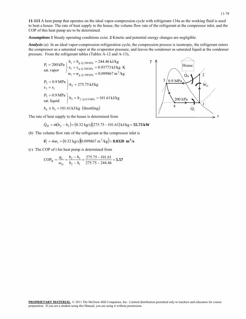
11-78
11-113 A heat pump that operates on the ideal vapor-compression cycle with refrigerant-134a as the working fluid is used to heat a house. The rate of heat supply to the house, the volume flow rate of the refrigerant at the compressor inlet, and the COP of this heat pump are to be determined.
Assumptions 1 Steady operating conditions exist. 2 Kinetic and potential energy changes are negligible.
Analysis (a) In an ideal vapor-compression refrigeration cycle, the compression process is isentropic, the refrigerant enters the compressor as a saturated vapor at the evaporator pressure, and leaves the condenser as saturated liquid at the condenser pressure. From the refrigerant tables (Tables A-12 and A-13),
QH
QL
200 kPa 1
23
4
0.9 MPa Win·
·
·
House
( )throttling kJ/kg 61.101
kJ/kg 61.101liquid sat.
MPa 9.0
kJ/kg 75.275MPa 9.0
/kgm 099867.0KkJ/kg 93773.0
kJ/kg 46.244
vaporsat.kPa 200
34
MPa 0.9 @ 33
212
2
3kPa 200 @ 1
kPa 200 @ 1
kPa 200 @ 11
=≅
==⎭⎬⎫=
=⎭⎬⎫
==
==
⋅====
⎭⎬⎫=
hh
hhP
hss
P
sshh
P
f
g
g
g
vv
T
s The rate of heat supply to the house is determined from
( ) ( )( ) kW 55.73=−=−= kJ/kg .61101275.75kg/s 0.3232 hhmQH &&
(b) The volume flow rate of the refrigerant at the compressor inlet is
( )( ) /sm 0.0320 3=== /kgm 0.099867kg/s 0.32 311 vV m&&
(c) The COP of t his heat pump is determined from
5.57=−−
=−−
==46.24475.27561.10175.275COP
12
32
inR hh
hhwqL
PROPRIETARY MATERIALpreparation. If you are a student using this Manual, you are using it without permission.
. © 2011 The McGraw-Hill Companies, Inc. Limited distribution permitted only to teachers and educators for course
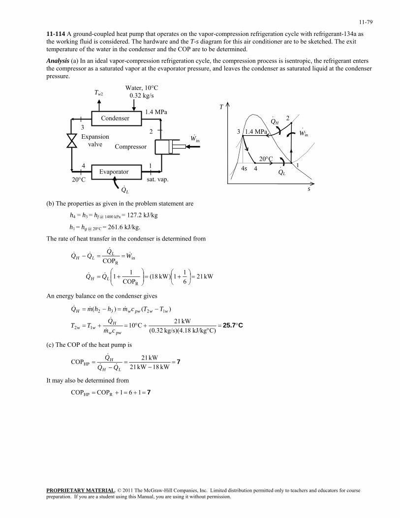
11-79
11-114 A ground-coupled heat pump that operates on the vapor-compression refrigeration cycle with refrigerant-134a as the working fluid is considered. The hardware and the T-s diagram for this air conditioner are to be sketched. The exit temperature of the water in the condenser and the COP are to be determined.
Analysis (a) In an ideal vapor-compression refrigeration cycle, the compression process is isentropic, the refrigerant enters the compressor as a saturated vapor at the evaporator pressure, and leaves the condenser as saturated liquid at the condenser pressure.
1
2 3
4
20°C
Condenser
Evaporator
Compressor Expansion
valve
1.4 MPa
inW&
Tw2Water, 10°C
0.32 kg/s
sat. vap.
QH
QL
20°C 1
3
4
1.4 MPa W n·
i·
·
· 2
4s
s
T
LQ&
(b) The properties as given in the problem statement are
h4 = h3 = hf @ 1400 kPa = 127.2 kJ/kg
h1 = hg @ 20°C = 261.6 kJ/kg.
The rate of heat transfer in the condenser is determined from
kW 21
611)kW 18(
COP11
COP
R
inR
=⎟⎠⎞
⎜⎝⎛ +=⎟⎟
⎠
⎞⎜⎜⎝
⎛+=
==−
LH
LLH
WQ
&&
&&
&&
An energy balance on the condenser gives
C25.7°=
°+°=+=
−=−=
C)kJ/kg kg/s)(4.18 32.0(kW 21C10
)()(
12
1232
pww
Hww
wwpwwH
cmQ
TT
TTcmhhmQ
&
&
&&&
(c) The COP of the heat pump is
7=−
=−
=kW 18kW 21
kW 21COPHPLH
H
QQQ
&&
&
It may also be determined from
7=+=+= 161COPCOP RHP
PROPRIETARY MATERIALpreparation. If you are a student using this Manual, you are using it without permission.
. © 2011 The McGraw-Hill Companies, Inc. Limited distribution permitted only to teachers and educators for course
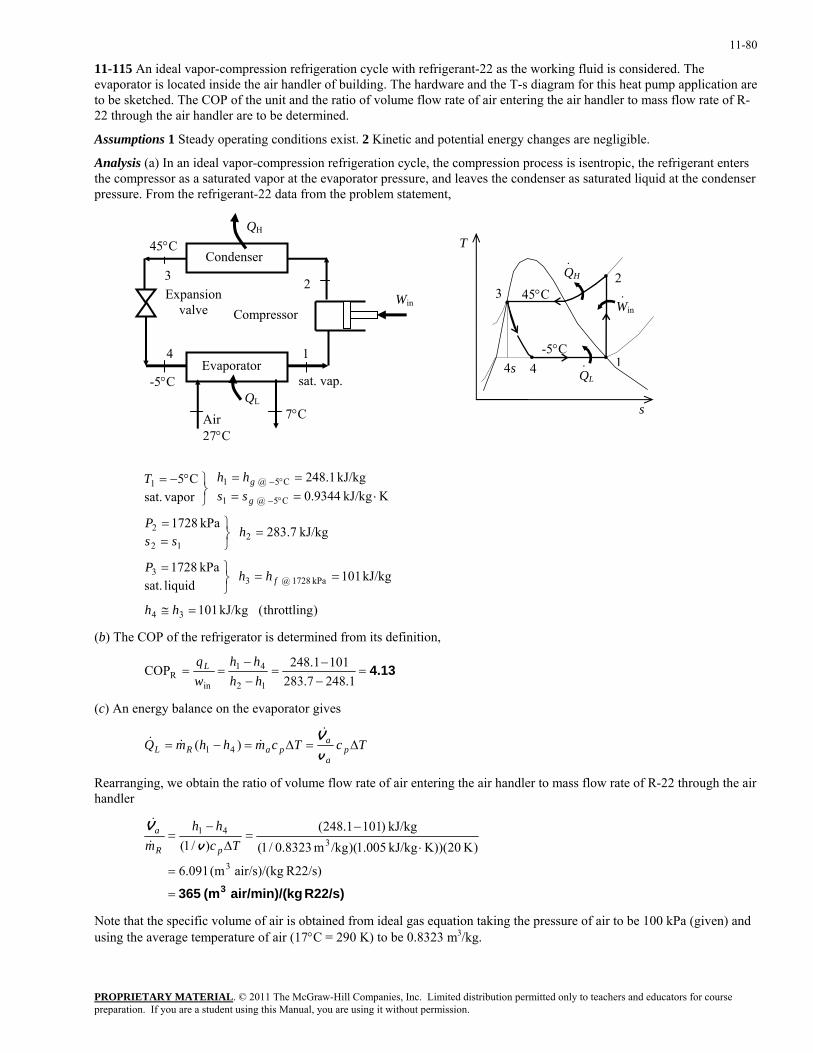
11-80
11-115 An ideal vapor-compression refrigeration cycle with refrigerant-22 as the working fluid is considered. The evaporator is located inside the air handler of building. The hardware and the T-s diagram for this heat pump application are to be sketched. The COP of the unit and the ratio of volume flow rate of air entering the air handler to mass flow rate of R-22 through the air handler are to be determined.
Assumptions 1 Steady operating conditions exist. 2 Kinetic and potential energy changes are negligible.
Analysis (a) In an ideal vapor-compression refrigeration cycle, the compression process is isentropic, the refrigerant enters the compressor as a saturated vapor at the evaporator pressure, and leaves the condenser as saturated liquid at the condenser pressure. From the refrigerant-22 data from the problem statement,
1
2 3
4
QH
-5°C
Win
Condenser
Evaporator
Compressor Expansion
valve
45°C
QL
Air 27°C
sat. vap.
QH
QL
-5°C 1
2 3
4
45°C
·
Win·
·4s
s
T
7°C
)throttling( kJ/kg 101
kJ/kg 101 liquid sat.kPa 1728
kJ/kg 7.283 kPa 1728
KkJ/kg 9344.0kJ/kg 1.248
vapor sat.
C5
34
kPa 1728 @ 33
212
2
C5 @ 1
C5 @ 11
=≅
==⎭⎬⎫=
=⎭⎬⎫
==
⋅====
⎭⎬⎫°−=
°−
°−
hh
hhP
hss
P
sshhT
f
g
g
(b) The COP of the refrigerator is determined from its definition,
4.13=−−
=−−
==1.2487.283
1011.248COP12
41
inR hh
hhwqL
(c) An energy balance on the evaporator gives
TcTcmhhmQ pa
apaRL ∆=∆=−=
v
V&&&& )( 41
Rearranging, we obtain the ratio of volume flow rate of air entering the air handler to mass flow rate of R-22 through the air handler
R22/s) kgair/min)/( (m 365 3=
=
⋅
−=
∆−
=
R22/s) air/s)/(kg (m 091.6
)K 20)(K)kJ/kg 005.1)(/kgm 8323.0/1(kJ/kg )1011.248(
)/1(3
341
Tchh
m pR
a
v
V&
&
Note that the specific volume of air is obtained from ideal gas equation taking the pressure of air to be 100 kPa (given) and using the average temperature of air (17°C = 290 K) to be 0.8323 m3/kg.
PROPRIETARY MATERIALpreparation. If you are a student using this Manual, you are using it without permission.
. © 2011 The McGraw-Hill Companies, Inc. Limited distribution permitted only to teachers and educators for course
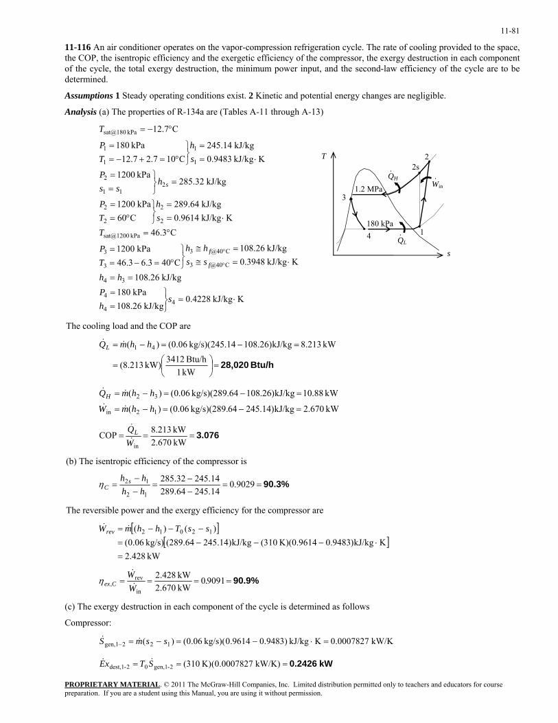
11-81
11-116 An air conditioner operates on the vapor-compression refrigeration cycle. The rate of cooling provided to the space, the COP, the isentropic efficiency and the exergetic efficiency of the compressor, the exergy destruction in each component of the cycle, the total exergy destruction, the minimum power input, and the second-law efficiency of the cycle are to be determined.
Assumptions 1 Steady operating conditions exist. 2 Kinetic and potential energy changes are negligible.
Analysis (a) The properties of R-134a are (Tables A-11 through A-13)
KkJ/kg 4228.0kJ/kg 26.108
kPa 180kJ/kg 26.108
KkJ/kg 3948.0kJ/kg 26.108
C403.63.46kPa 1200
C3.46KkJ/kg 9614.0
kJ/kg 64.289C60
kPa 1200
kJ/kg 32.285kPa 1200
KkJ/kg 9483.0kJ/kg 14.245
C107.27.12kPa 180
C7.12
44
4
34
C@403
C@403
3
3
kPa sat@1200
2
2
2
2
211
2
1
1
1
1
kPa sat@180
⋅=⎭⎬⎫
==
==
⋅=≅=≅
⎭⎬⎫
°=−==
°=
⋅==
⎭⎬⎫
°==
=⎭⎬⎫
==
⋅==
⎭⎬⎫
°=+−==
°−=
°
°
shP
hh
sshh
TP
Tsh
TP
hss
P
sh
TP
T
f
f
sQH
QL
180 kPa 1
2s
3
4
s
T
1.2 MPa
2
Win·
·
·
The cooling load and the COP are
Btu/h 28,020=⎟
⎠⎞
⎜⎝⎛=
=−=−=
kW 1Btu/h 3412kW) (8.213
kW 8.213kJ/kg)26.10814.245kg/s)( 06.0()( 41 hhmQL &&
kW 88.10kJ/kg)26.10864.289kg/s)( 06.0()( 32 =−=−= hhmQH &&
kW 670.2kJ/kg)14.24564kg/s)(289. 06.0()( 12in =−=−= hhmW &&
3.076===kW 670.2kW 213.8COP
inWQL&
&
(b) The isentropic efficiency of the compressor is
90.3%==−−
=−−
= 9029.014.24564.28914.24532.285
12
12
hhhh s
Cη
The reversible power and the exergy efficiency for the compressor are
[ ]
[ ]kW 428.2
KkJ/kg)9483.0K)(0.9614 310(kJ/kg)14.245(289.64kg/s) 06.0()()( 12012
=⋅−−−=
−−−= ssThhmWrev &&
90.9%==== 90910kW 670.2kW 428.2
in
rev, .
WW
Cex &
&η
(c) The exergy destruction in each component of the cycle is determined as follows
Compressor:
kW/K 0007827.0KkJ/kg )9483.09614.0kg/s)( 06.0()( 122gen,1 =⋅−=−=− ssmS &&
kW 0.2426=== kW/K) 0007827.0(K) 310(2-gen,102-dest,1 STxE &&
PROPRIETARY MATERIALpreparation. If you are a student using this Manual, you are using it without permission.
. © 2011 The McGraw-Hill Companies, Inc. Limited distribution permitted only to teachers and educators for course
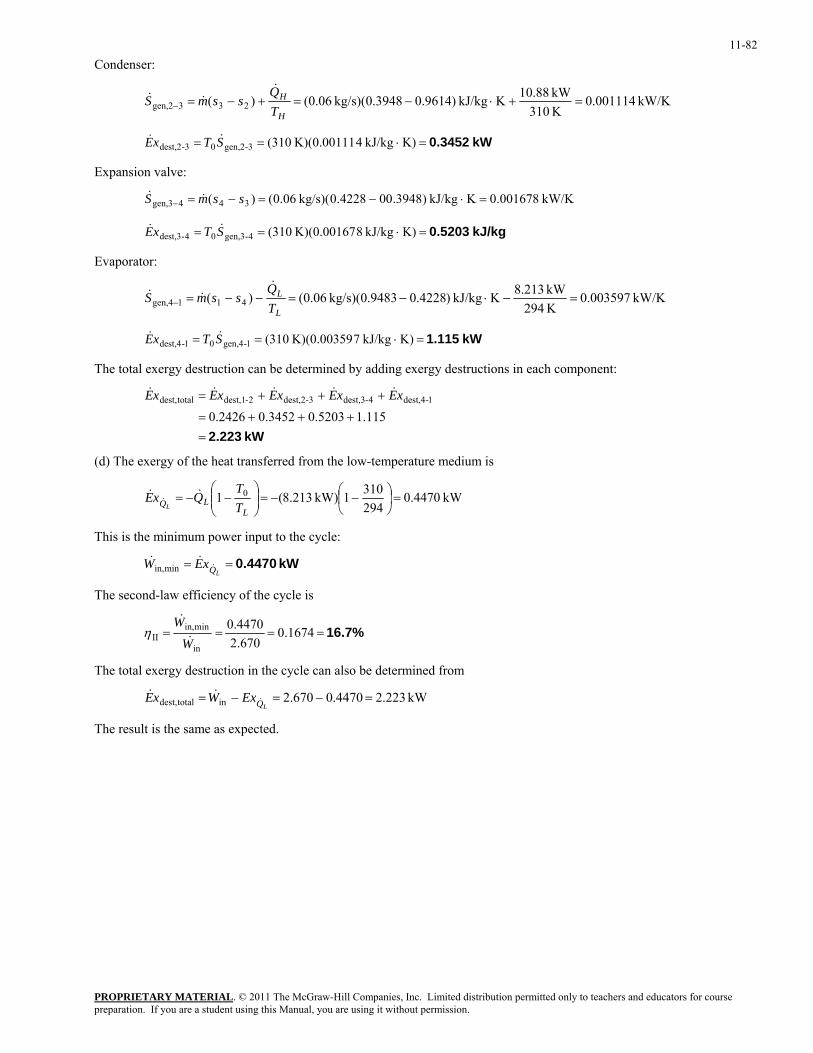
11-82
Condenser:
kW/K 001114.0K 310kW 88.10KkJ/kg )9614.03948.0(kg/s) 06.0()( 233gen,2 =+⋅−=+−=−
H
H
TQ
ssmS&
&&
kW 0.3452=⋅== K)kJ/kg 4K)(0.00111 (3103-gen,203-dest,2 STxE &&
Expansion valve:
kW/K 001678.0KkJ/kg )3948.004228.0kg/s)( 06.0()( 344gen,3 =⋅−=−=− ssmS &&
kJ/kg 0.5203=⋅== K)kJ/kg 8K)(0.00167 (3104-gen,304-dest,3 STxE &&
Evaporator:
kW/K 003597.0K 294kW 213.8KkJ/kg )4228.09483.0(kg/s) 06.0()( 411gen,4 =−⋅−=−−=−
L
L
TQ
ssmS&
&&
kW 1.115=⋅== K)kJ/kg 7K)(0.00359 (3101-gen,401-dest,4 STxE &&
The total exergy destruction can be determined by adding exergy destructions in each component:
kW 2.223=
+++=
+++=
115.15203.03452.02426.01-dest,44-dest,33-dest,22-dest,1totaldest, xExExExExE &&&&&
(d) The exergy of the heat transferred from the low-temperature medium is
kW 4470.02943101kW) 213.8(1 0 =⎟
⎠⎞
⎜⎝⎛ −−=⎟⎟
⎠
⎞⎜⎜⎝
⎛−−=
LLQ T
TQxE
L
&&&
This is the minimum power input to the cycle:
kW 0.4470==LQxEW &
&&minin,
The second-law efficiency of the cycle is
16.7%==== 0.1674670.2
4470.0
in
minin,II W
W&
&η
The total exergy destruction in the cycle can also be determined from
kW 223.24470.0670.2intotaldest, =−=−=LQExWxE &
&&
The result is the same as expected.
PROPRIETARY MATERIALpreparation. If you are a student using this Manual, you are using it without permission.
. © 2011 The McGraw-Hill Companies, Inc. Limited distribution permitted only to teachers and educators for course
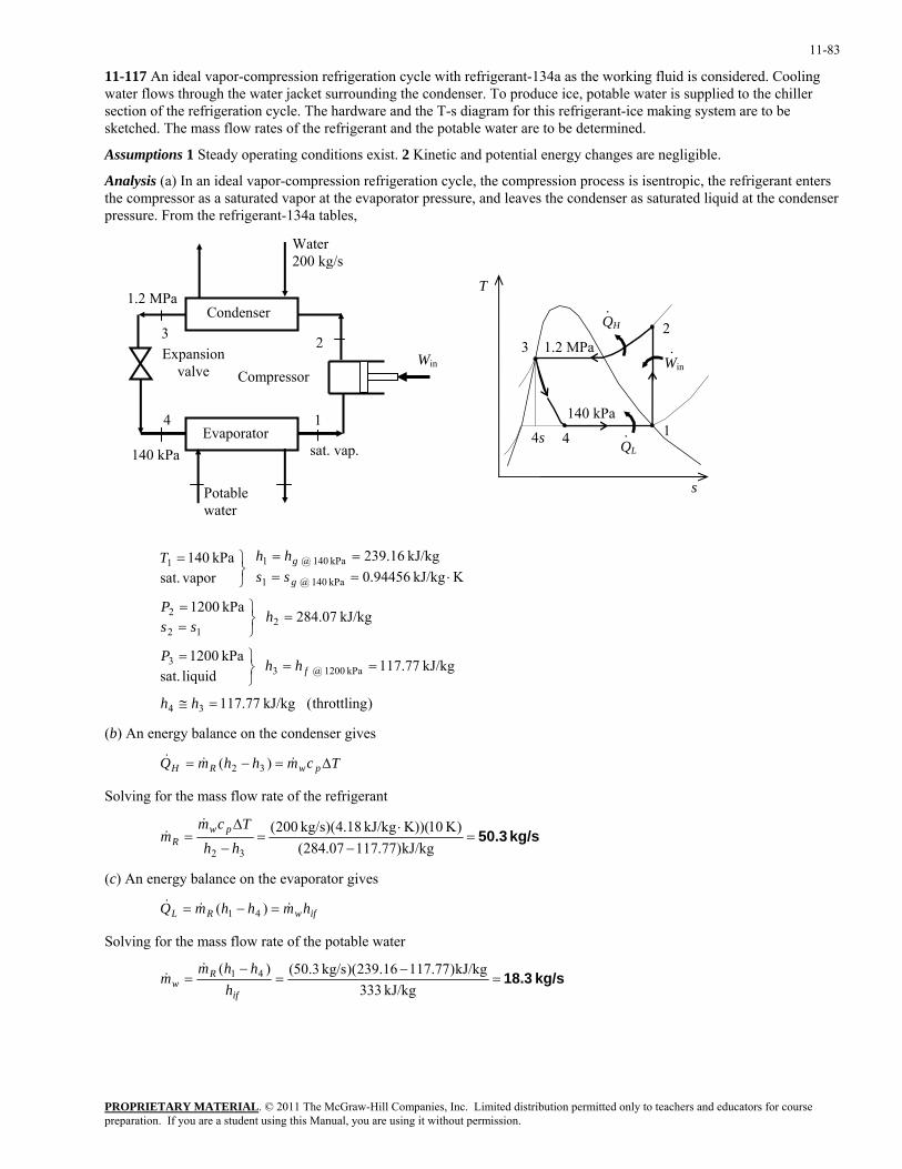
11-83
11-117 An ideal vapor-compression refrigeration cycle with refrigerant-134a as the working fluid is considered. Cooling water flows through the water jacket surrounding the condenser. To produce ice, potable water is supplied to the chiller section of the refrigeration cycle. The hardware and the T-s diagram for this refrigerant-ice making system are to be sketched. The mass flow rates of the refrigerant and the potable water are to be determined.
Assumptions 1 Steady operating conditions exist. 2 Kinetic and potential energy changes are negligible.
Analysis (a) In an ideal vapor-compression refrigeration cycle, the compression process is isentropic, the refrigerant enters the compressor as a saturated vapor at the evaporator pressure, and leaves the condenser as saturated liquid at the condenser pressure. From the refrigerant-134a tables,
1
2 3
4
140 kPa
Win
Condenser
Evaporator
Compressor Expansion
valve
Water 200 kg/s
1.2 MPa
Potable water
sat. vap.
QH
QL
140 kPa1
2 3
4
1.2 MPa
·
Win·
·4s
s
T
)throttling( kJ/kg 77.117
kJ/kg 77.117 liquid sat.kPa 1200
kJ/kg 07.284 kPa 1200
KkJ/kg 94456.0kJ/kg 16.239
vapor sat.
kPa 140
34
kPa 1200 @ 33
212
2
kPa 140 @ 1
kPa 140 @ 11
=≅
==⎭⎬⎫=
=⎭⎬⎫
==
⋅====
⎭⎬⎫=
hh
hhP
hss
P
sshhT
f
g
g
(b) An energy balance on the condenser gives
TcmhhmQ pwRH ∆=−= &&& )( 32
Solving for the mass flow rate of the refrigerant
kg/s 50.3=−
⋅=
−
∆=
kJ/kg)77.11707.284()K 10)(K)kJ/kg 18.4)(kg/s 200(
32 hhTcm
m pwR
&&
(c) An energy balance on the evaporator gives
ifwRL hmhhmQ &&& =−= )( 41
Solving for the mass flow rate of the potable water
kg/s 18.3=−
=−
=kJ/kg 333
kJ/kg)77.11716.239)(kg/s 3.50()( 41
if
Rw h
hhmm
&&
PROPRIETARY MATERIALpreparation. If you are a student using this Manual, you are using it without permission.
. © 2011 The McGraw-Hill Companies, Inc. Limited distribution permitted only to teachers and educators for course
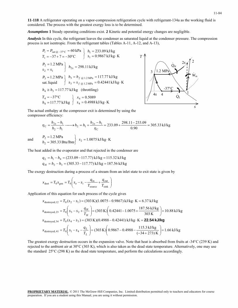
11-84
11-118 A refrigerator operating on a vapor-compression refrigeration cycle with refrigerant-134a as the working fluid is considered. The process with the greatest exergy loss is to be determined.
Assumptions 1 Steady operating conditions exist. 2 Kinetic and potential energy changes are negligible.
Analysis In this cycle, the refrigerant leaves the condenser as saturated liquid at the condenser pressure. The compression process is not isentropic. From the refrigerant tables (Tables A-11, A-12, and A-13),
KkJ/kg 4988.05089.0
kJ/kg 77.117C37
)throttling( kJ/kg 77.117
KkJ/kg 42441.0kJ/kg 77.117
liquid sat.
MPa 2.1
kJ/kg 11.298 MPa 2.1
KkJ/kg 9867.0kJ/kg 09.233
C30737kPa 60
4
4
4
4
34
MPa 1.2 @ 3
MPa 1.2 @ 33
212
2
1
1
1
C37 @sat 1
⋅==
⎭⎬⎫
=°−=
=≅
⋅====
⎭⎬⎫=
=⎭⎬⎫
==
⋅==
⎭⎬⎫
°−=+−=
== °−
sx
hT
hh
sshhP
hss
P
sh
TPP
f
f
s
QH
QL
-37°C 1
2s
3
4
1.2 MPa
2
Win·
·
·
4s
s
T
The actual enthalpy at the compressor exit is determined by using the compressor efficiency:
kJ/kg 33.30590.0
09.23311.29809.233C
1212
12
12C =
−+=
−+=⎯→⎯
−−
=η
ηhh
hhhhhh ss
and KkJ/kg 0075.1 Btu/lbm 33.305
MPa 2.12
2
2 ⋅=⎭⎬⎫
==
shP
The heat added in the evaporator and that rejected in the condenser are
kJ/kg 56.187kJ/kg )77.11733.305(kJ/kg 32.115kJ/kg )77.11709.233(
32
41
=−=−==−=−=
hhqhhq
H
L
The exergy destruction during a process of a stream from an inlet state to exit state is given by
⎟⎟⎠
⎞⎜⎜⎝
⎛+−−==
sink
out
source
in0gen0dest T
qT
qssTsTx ie
Application of this equation for each process of the cycle gives
kJ/kg 66.1K 273)34(
kJ/kg 3.1154988.09867.0)K 303(
KkJ/kg )42441.04988.0)(K 303()(
kJ/kg 88.10K 303kJ/kg 56.187
0075.142441.0)K 303(
kJ/kg 37.6KkJ/kg )9867.00075.1)(K 303()(
41041 destroyed,
34034 destroyed,
23023 destroyed,
12012 destroyed,
=⎟⎟⎠
⎞⎜⎜⎝
⎛+−
−−=⎟⎟⎠
⎞⎜⎜⎝
⎛−−=
=⋅−=−=
=⎟⎠
⎞⎜⎝
⎛ +−=⎟⎟⎠
⎞⎜⎜⎝
⎛+−=
=⋅−=−=
L
L
H
H
Tq
ssTx
ssTxTq
ssTx
ssTx
kJ/kg 22.54
The greatest exergy destruction occurs in the expansion valve. Note that heat is absorbed from fruits at -34°C (239 K) and rejected to the ambient air at 30°C (303 K), which is also taken as the dead state temperature. Alternatively, one may use the standard 25°C (298 K) as the dead state temperature, and perform the calculations accordingly.
PROPRIETARY MATERIALpreparation. If you are a student using this Manual, you are using it without permission.
. © 2011 The McGraw-Hill Companies, Inc. Limited distribution permitted only to teachers and educators for course
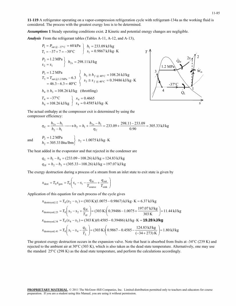
11-85
11-119 A refrigerator operating on a vapor-compression refrigeration cycle with refrigerant-134a as the working fluid is considered. The process with the greatest exergy loss is to be determined.
Assumptions 1 Steady operating conditions exist. 2 Kinetic and potential energy changes are negligible.
Analysis From the refrigerant tables (Tables A-11, A-12, and A-13),
KkJ/kg 4585.04665.0
kJ/kg 26.108C37
)throttling( kJ/kg 26.108
KkJ/kg 39486.0kJ/kg 26.108
C403.63.46
3.6MPa 2.1
kJ/kg 11.298 MPa 2.1
KkJ/kg 9867.0kJ/kg 09.233
C30737kPa 60
4
4
4
4
34
C40 @ 3
C40 @ 3MPa 1.2 @sat 3
3
212
2
1
1
1
C37 @sat 1
⋅==
⎭⎬⎫
=°−=
=≅
⋅=≅=≅
⎪⎭
⎪⎬
⎫
°=−=
−==
=⎭⎬⎫
==
⋅==
⎭⎬⎫
°−=+−=
==
°
°
°−
sx
hT
hh
sshh
TTP
hss
P
sh
TPP
f
f
s
QH
QL
-37°C 1
2s
3
4
1.2 MPa
2
Win·
·
·
s
T
The actual enthalpy at the compressor exit is determined by using the compressor efficiency:
kJ/kg 33.30590.0
09.23311.29809.233C
1212
12
12C =
−+=
−+=⎯→⎯
−−
=η
ηhh
hhhhhh ss
and KkJ/kg 0075.1 Btu/lbm 33.305
MPa 2.12
2
2 ⋅=⎭⎬⎫
==
shP
The heat added in the evaporator and that rejected in the condenser are
kJ/kg 07.197kJ/kg )26.10833.305(
kJ/kg 83.124kJ/kg )26.10809.233(
32
41
=−=−==−=−=
hhqhhq
H
L
The exergy destruction during a process of a stream from an inlet state to exit state is given by
⎟⎟⎠
⎞⎜⎜⎝
⎛+−−==
sink
out
source
in0gen0dest T
qT
qssTsTx ie
Application of this equation for each process of the cycle gives
kJ/kg 80.1K 273)34(
kJ/kg 83.1244585.09867.0)K 303(
KkJ/kg )39486.04585.0)(K 303()(
kJ/kg 44.11K 303kJ/kg 07.197
0075.139486.0)K 303(
kJ/kg 37.6KkJ/kg )9867.00075.1)(K 303()(
41041 destroyed,
34034 destroyed,
23023 destroyed,
12012 destroyed,
=⎟⎟⎠
⎞⎜⎜⎝
⎛+−
−−=⎟⎟⎠
⎞⎜⎜⎝
⎛−−=
=⋅−=−=
=⎟⎠
⎞⎜⎝
⎛ +−=⎟⎟⎠
⎞⎜⎜⎝
⎛+−=
=⋅−=−=
L
L
H
H
Tq
ssTx
ssTxTq
ssTx
ssTx
kJ/kg 19.28
The greatest exergy destruction occurs in the expansion valve. Note that heat is absorbed from fruits at -34°C (239 K) and rejected to the ambient air at 30°C (303 K), which is also taken as the dead state temperature. Alternatively, one may use the standard 25°C (298 K) as the dead state temperature, and perform the calculations accordingly.
PROPRIETARY MATERIALpreparation. If you are a student using this Manual, you are using it without permission.
. © 2011 The McGraw-Hill Companies, Inc. Limited distribution permitted only to teachers and educators for course
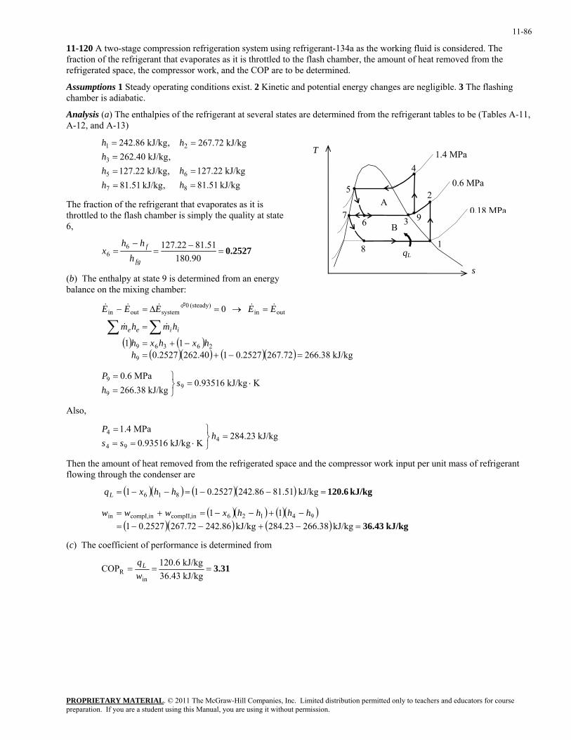
11-86
11-120 A two-stage compression refrigeration system using refrigerant-134a as the working fluid is considered. The fraction of the refrigerant that evaporates as it is throttled to the flash chamber, the amount of heat removed from the refrigerated space, the compressor work, and the COP are to be determined.
Assumptions 1 Steady operating conditions exist. 2 Kinetic and potential energy changes are negligible. 3 The flashing chamber is adiabatic.
Analysis (a) The enthalpies of the refrigerant at several states are determined from the refrigerant tables to be (Tables A-11, A-12, and A-13)
kJ/kg 51.81kJ/kg 22.127
kJ/kg 72.267
,kJ/kg 51.81,kJ/kg 22.127,kJ/kg 40.262,kJ/kg 86.242
8
6
2
7
5
3
1
==
=
====
hh
h
hhhh
T
qL
0.18 MPa
1
2 5
8
0.6 MPa
9 67
3 B
A
1.4 MPa 4
The fraction of the refrigerant that evaporates as it is throttled to the flash chamber is simply the quality at state 6,
0.2527=−
=−
=90.180
51.8122.12766
fg
f
hhh
x
s (b) The enthalpy at state 9 is determined from an energy balance on the mixing chamber:
( ) ( )
( )( ) ( )( ) kJ/kg 38.26672.2672527.0140.2622527.011
0
9
26369
outin(steady) 0
systemoutin
=−+=−+=
=
=→=∆=−
∑∑h
hxhxh
hmhm
EEEEE
iiee &&
&&&&&
KkJ/kg 93516.0kJ/kg 38.266
MPa 6.09
9
9 ⋅=⎭⎬⎫
==
shP
Also,
kJ/kg 23.284KkJ/kg 93516.0
MPa 4.14
94
4 =⎭⎬⎫
⋅===
hss
P
Then the amount of heat removed from the refrigerated space and the compressor work input per unit mass of refrigerant flowing through the condenser are
( )( ) ( )( )
( )( ) ( )( )( )( ) ( ) kJ/kg 36.43
kJ/kg 120.6
=−+−−=−+−−=+=
=−−=−−=
kJ/kg 266.38284.23kJ/kg 242.86267.720.2527111
kJ/kg .5181242.862527.011
94126incompII,incompI,in
816
hhhhxwww
hhxqL
(c) The coefficient of performance is determined from
3.31===kJ/kg 36.43kJ/kg 120.6COP
inR w
qL
PROPRIETARY MATERIALpreparation. If you are a student using this Manual, you are using it without permission.
. © 2011 The McGraw-Hill Companies, Inc. Limited distribution permitted only to teachers and educators for course
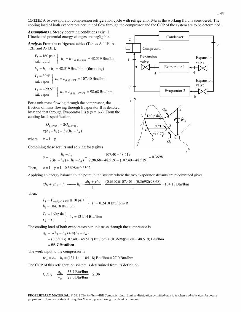
11-87
11-121E A two-evaporator compression refrigeration cycle with refrigerant-134a as the working fluid is considered. The cooling load of both evaporators per unit of flow through the compressor and the COP of the system are to be determined.
Assumptions 1 Steady operating conditions exist. 2 Kinetic and potential energy changes are negligible.
45
6
Compressor
Expansion valve1
2
Evaporator 2
Expansion valve
Expansion valve
Condenser
Evaporator 1
7
Analysis From the refrigerant tables (Tables A-11E, A-12E, and A-13E),
3
Btu/lbm 68.98 vapor sat.
F5.29
Btu/lbm 40.107 vapor sat.
F30
)throttling( Btu/lbm 519.48
Btu/lbm 519.48 liquid sat.psia 160
F5.29 @ 77
F30 @ 55
364
psia 160 @ 33
==⎭⎬⎫°−=
==⎭⎬⎫°=
=≅=
==⎭⎬⎫=
°−
°
g
g
f
hhT
hhT
hhh
hhP
PROPRIETARY MATERIAL. © 2011 The McGraw-Hill Companies, Inc. Limited distribution permitted only to teachers and educators for course
For a unit mass flowing through the compressor, the fraction of mass flowing through Evaporator II is denoted by x and that through Evaporator I is y (y = 1-x). From the cooling loads specification,
)(2)(
2
6745
2 vape,1 vape,
hhyhhx
QQ LL
−=−
= &&
where yx −= 1
Combining these results and solving for y gives
3698.0)519.4840.107()519.4868.98(2
519.4840.107)()(2 4567
45 =−+−
−=
−+−−
=hhhh
hhy
QH
QL
-29.5°F 1
2
3
6
160 psiaWin·
·
·
45
7
30°F
s
T
Then, 6302.03698.011 =−=−= yx
Applying an energy balance to the point in the system where the two evaporator streams are recombined gives
Btu/lbm 18.1041
)68.98)(3698.0()40.107)(6302.0(1
751175 =
+=
+=⎯→⎯=+
yhxhhhyhxh
Then,
Btu/lbm 14.131 psia 160
RBtu/lbm 2418.0 Btu/lbm 18.104
psia 10
212
2
11
F29.5 @sat 1
=⎭⎬⎫
==
⋅=⎭⎬⎫
=≅= °−
hss
P
sh
PP
The cooling load of both evaporators per unit mass through the compressor is
Btu/lbm 55.7=
−+−=−+−=
Btu/lbm )519.48(98.68)3698.0(Btu/lbm )519.48(107.40)6302.0()()( 6745 hhyhhxqL
The work input to the compressor is Btu/lbm 27.0Btu/lbm )18.104(131.1412in =−=−= hhw
The COP of this refrigeration system is determined from its definition,
2.06===Btu/lbm 27.0Btu/lbm 55.7COP
inR w
qL
preparation. If you are a student using this Manual, you are using it without permission.
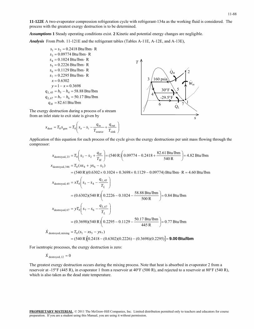
11-88
11-122E A two-evaporator compression refrigeration cycle with refrigerant-134a as the working fluid is considered. The process with the greatest exergy destruction is to be determined.
Assumptions 1 Steady operating conditions exist. 2 Kinetic and potential energy changes are negligible.
Analysis From Prob. 11-121E and the refrigerant tables (Tables A-11E, A-12E, and A-13E),
Btu/lbm 61.82Btu/lbm 17.50Btu/lbm 88.58
3698.016302.0
RBtu/lbm 2295.0RBtu/lbm 1129.0RBtu/lbm 2226.0RBtu/lbm 1024.0
RBtu/lbm 09774.0RBtu/lbm 2418.0
6767,
4545,
7
6
5
4
3
21
==−==−=
=−==
⋅=⋅=⋅=⋅=
⋅=⋅==
H
L
L
qhhqhhq
xyx
sssss
ss
QH
QL
-29.5°F1
2
3
6
160 psiaWin·
·
·
45
7
30°F
s
T
The exergy destruction during a process of a stream from an inlet state to exit state is given by
⎟⎟⎠
⎞⎜⎜⎝
⎛+−−==
sink
out
source
in0gen0dest T
qT
qssTsTx ie
Application of this equation for each process of the cycle gives the exergy destructions per unit mass flowing through the compressor:
[ ] Btu/lbm 9.00=−−=
−−=
=⎟⎠⎞
⎜⎝⎛ −−=
⎟⎟⎠
⎞⎜⎜⎝
⎛−−=
=⎟⎠⎞
⎜⎝⎛ −−=
⎟⎟⎠
⎞⎜⎜⎝
⎛−−=
=⋅−×+×=
−+=
=⎟⎠⎞
⎜⎝⎛ +−=⎟⎟
⎠
⎞⎜⎜⎝
⎛+−=
)2295.0)(3698.0()2226.0)(6302.0(2418.0)R 540(
)(
Btu/lbm 77.0R 445
Btu/lbm 17.501129.02295.0)R 540)(3698.0(
Btu/lbm 84.0R 500
Btu/lbm 88.581024.02226.0)R 540)(6302.0(
Btu/lbm 60.4RBtu/lbm )09774.01129.03698.01024.06302.0)(R 540(
)(
Btu/lbm .824R 540
Btu/lbm 61.822418.009774.0)R 540(
7510mixing destroyed,
67,67067 destroyed,
45,45045 destroyed,
3640346 destroyed,
23023 destroyed,
ysxssTX
Tq
ssyTx
Tq
ssxTx
sysxsTxTq
ssTx
L
L
L
L
H
H
&
For isentropic processes, the exergy destruction is zero:
012 destroyed, =X&
The greatest exergy destruction occurs during the mixing process. Note that heat is absorbed in evaporator 2 from a reservoir at -15°F (445 R), in evaporator 1 from a reservoir at 40°F (500 R), and rejected to a reservoir at 80°F (540 R), which is also taken as the dead state temperature.
PROPRIETARY MATERIALpreparation. If you are a student using this Manual, you are using it without permission.
. © 2011 The McGraw-Hill Companies, Inc. Limited distribution permitted only to teachers and educators for course
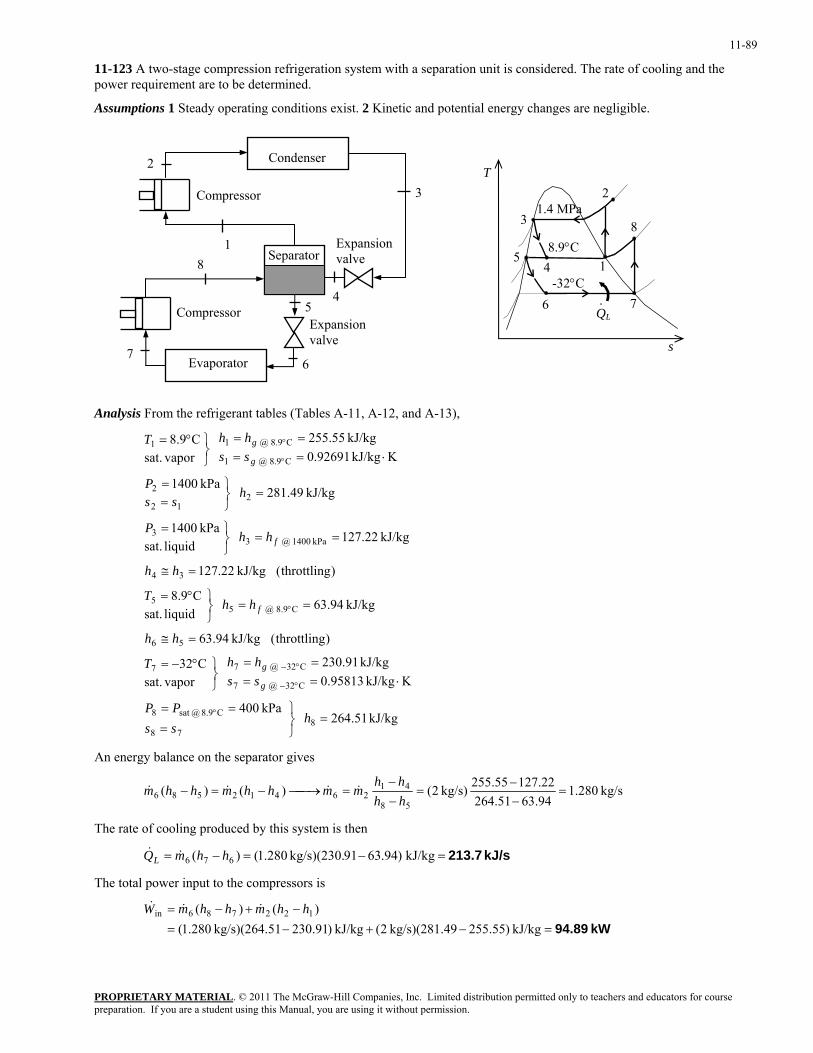
11-89
11-123 A two-stage compression refrigeration system with a separation unit is considered. The rate of cooling and the power requirement are to be determined.
Assumptions 1 Steady operating conditions exist. 2 Kinetic and potential energy changes are negligible.
45
6
Compressor
Expansion valve
1
2
Evaporator 7
Separator
Condenser
Expansion valve
Compressor
8
QL
-32°C 7
8 3
6 ·
48.9°C
51
1.4 MPa 2
s
T 3
Analysis From the refrigerant tables (Tables A-11, A-12, and A-13),
kJ/kg 51.264 kPa 400
KkJ/kg 95813.0kJ/kg 91.230
vapor sat.
C32
)throttling( kJ/kg 94.63
kJ/kg 94.63 liquid sat.C9.8
)throttling( kJ/kg 22.127
kJ/kg 22.127 liquid sat.kPa 1400
kJ/kg 49.281 kPa 1400
KkJ/kg 92691.0kJ/kg 55.255
vapor sat.
C9.8
878
C8.9 @sat 8
C32 @ 7
C32 @ 77
56
C9.8 @ 55
34
kPa 0014 @ 33
212
2
C9.8 @ 1
C9.8 @ 11
=⎭⎬⎫
=
==
⋅====
⎭⎬⎫°−=
=≅
==⎭⎬⎫°=
=≅
==⎭⎬⎫=
=⎭⎬⎫
==
⋅====
⎭⎬⎫°=
°
°−
°−
°
°
°
hssPP
sshhT
hh
hhT
hh
hhP
hss
P
sshhT
g
g
f
f
g
g
An energy balance on the separator gives
kg/s 280.194.6351.26422.12755.255kg/s) 2()()(
58
4126412586 =
−−
=−−
=⎯→⎯−=−hhhh
mmhhmhhm &&&&
The rate of cooling produced by this system is then
kJ/s 213.7=−=−= kJ/kg )94.6391kg/s)(230. 280.1()( 676 hhmQL &&
The total power input to the compressors is
kW 94.89=−+−=
−+−=kJ/kg )55.25549kg/s)(281. 2(kJ/kg )91.23051kg/s)(264. 280.1(
)()( 122786in hhmhhmW &&&
PROPRIETARY MATERIALpreparation. If you are a student using this Manual, you are using it without permission.
. © 2011 The McGraw-Hill Companies, Inc. Limited distribution permitted only to teachers and educators for course
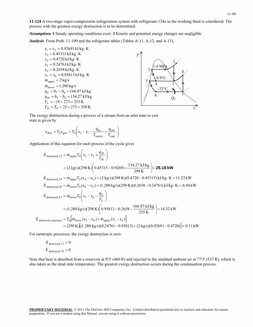
11-90
11-124 A two-stage vapor-compression refrigeration system with refrigerant-134a as the working fluid is considered. The process with the greatest exergy destruction is to be determined.
Assumptions 1 Steady operating conditions exist. 2 Kinetic and potential energy changes are negligible.
Analysis From Prob. 11-109 and the refrigerant tables (Tables A-11, A-12, and A-13),
K 29827325K 25527318kJ/kg 27.154kJ/kg 97.166
kg/s 280.1kg/s 2
KkJ/kg 95813.0KkJ/kg 2658.0KkJ/kg 24761.0
KkJ/kg 4720.0KkJ/kg 45315.0
KkJ/kg 92691.0
0
32
67
lower
upper
87
6
5
4
3
21
=+===+−=
=−==−=
==
⋅==⋅=⋅=
⋅=⋅=
⋅==
TTT
hhqhhq
mm
ssssss
ss
H
L
H
L
&
&
QL
-32°C7
8 3
6 ·
48.9°C
51
1.4 MPa 2
s
T
The exergy destruction during a process of a stream from an inlet state to exit state is given by
⎟⎟⎠
⎞⎜⎜⎝
⎛+−−==
sink
out
source
in0gen0dest T
qT
qssTsTx ie
Application of this equation for each process of the cycle gives
[ ][ ] kW 11.0)4720.092691.0)(kg/s 2()95813.024761.0)(kg/s 280.1()K 298(
)()(
kW 32.14K 255kJ/kg 97.1662658.095813.0)K 298)(kg/s 280.1(
kW 94.6KkJ/kg )24761.02658.0)(K 298)(kg/s 280.1()(
kW 23.11KkJ/kg )45315.04720.0)(K 298)(kg/s 2()(
K 298kJ/kg 27.15492691.045315.0)K 298)(kg/s 2(
41upper85lower0separator destroyed,
670lower67 destroyed,
560lower56 destroyed,
340upper34 destroyed,
230upper23 destroyed,
=−+−=
−+−=
=⎟⎠
⎞⎜⎝
⎛ −−=
⎟⎟⎠
⎞⎜⎜⎝
⎛−−=
=⋅−=−=
=⋅−=−=
=⎟⎠
⎞⎜⎝
⎛ +−=
⎟⎟⎠
⎞⎜⎜⎝
⎛+−=
ssmssmTX
Tq
ssTmX
ssTmX
ssTmX
Tq
ssTmX
L
L
H
H
&&&
&&
&&
&&
&&
kW 26.18
For isentropic processes, the exergy destruction is zero:
0
0
78 destroyed,
12 destroyed,
=
=
X
X&
&
Note that heat is absorbed from a reservoir at 0°F (460 R) and rejected to the standard ambient air at 77°F (537 R), which is also taken as the dead state temperature. The greatest exergy destruction occurs during the condensation process.
PROPRIETARY MATERIALpreparation. If you are a student using this Manual, you are using it without permission.
. © 2011 The McGraw-Hill Companies, Inc. Limited distribution permitted only to teachers and educators for course
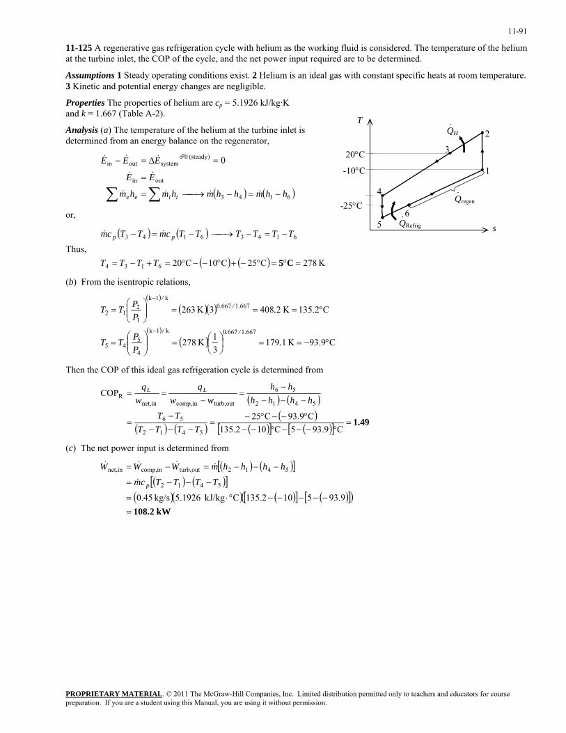
11-91
11-125 A regenerative gas refrigeration cycle with helium as the working fluid is considered. The temperature of the helium at the turbine inlet, the COP of the cycle, and the net power input required are to be determined.
Assumptions 1 Steady operating conditions exist. 2 Helium is an ideal gas with constant specific heats at room temperature. 3 Kinetic and potential energy changes are negligible.
Properties The properties of helium are cp = 5.1926 kJ/kg·K and k = 1.667 (Table A-2).
PROPRIETARY MATERIAL. © 2011 The McGraw-Hill Companies, Inc. Limited distribution permitted only to teachers and educators for course
)
T
1
3
-10°C
56
4
2QH·
QRefrig·
Qregen·
-25°C
Analysis (a) The temperature of the helium at the turbine inlet is determined from an energy balance on the regenerator,
20°C
( ) ( 6143
outin
(steady) 0systemoutin 0
hhmhhmhmhm
EE
EEE
iiee −=−⎯→⎯=
=
=∆=−
∑∑ &&&&
&&
&&&
or, s
Thus,
( ) ( )
( ) ( ) K 278C25C10C206134
61436143
=°=°−+°−−°=+−=
−=−⎯→⎯−=−
C5TTTT
TTTTTTcmTTcm pp &&
(b) From the isentropic relations,
( )( )( )
( )( ) C93.9K 1179
31 K278
C135.2 K24083 K263
66716670k1k
4
545
66716670k1k
1
212
°−==⎟⎠⎞
⎜⎝⎛=⎟⎟
⎠
⎞⎜⎜⎝
⎛=
°===⎟⎟⎠
⎞⎜⎜⎝
⎛=
−
−
.PPTT
.PPTT
././
././
Then the COP of this ideal gas refrigeration cycle is determined from
( ) ( )
( ) ( )( )
( )[ ] ( )[ ] 1.49=°−−−°−−
°−−°−=
−−−−
=
−−−−
=−
==
C93.95C10135.2C93.9C25
COP
5412
56
5412
56
outturb,incomp,innet,R
TTTTTT
hhhhhh
wwq
wq LL
(c) The net power input is determined from
( ) ( )[ ]( ) ( )[ ]
( )( ) ( )[ ] ( )[ ]( )kW 108.2=
−−−−−°⋅=
−−−=
−−−=−=
93.9510135.2CkJ/kg 5.1926kg/s 0.455412
5412outturb,incomp,innet,
TTTTcm
hhhhmWWW
p&
&&&&
preparation. If you are a student using this Manual, you are using it without permission.
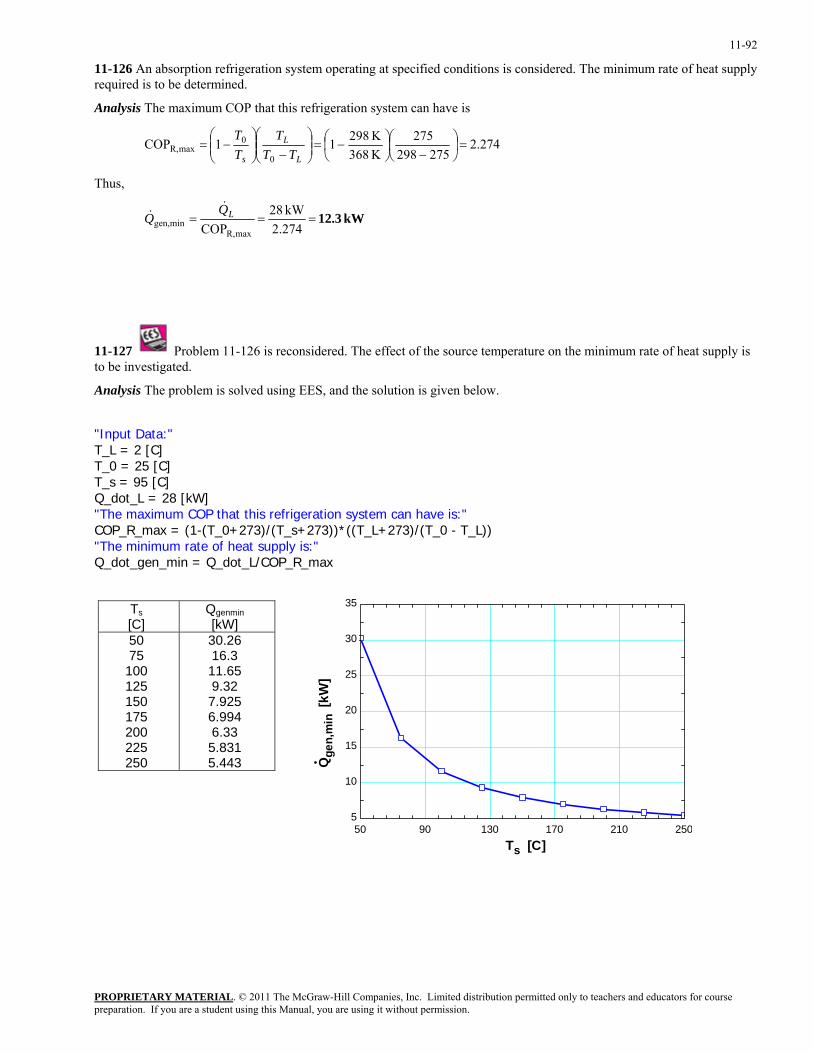
11-92
11-126 An absorption refrigeration system operating at specified conditions is considered. The minimum rate of heat supply required is to be determined.
Analysis The maximum COP that this refrigeration system can have is
274.2275298
275K 368K 29811COP
0
0maxR, =⎟
⎠⎞
⎜⎝⎛
−⎟⎠⎞
⎜⎝⎛ −=⎟⎟
⎠
⎞⎜⎜⎝
⎛−⎟⎟
⎠
⎞⎜⎜⎝
⎛−=
L
L
s TTT
TT
Thus,
kW3.12 2.274
kW 28COP maxR,
mingen, === LQQ
&&
11-127 Problem 11-126 is reconsidered. The effect of the source temperature on the minimum rate of heat supply is to be investigated.
Analysis The problem is solved using EES, and the solution is given below.
"Input Data:" T_L = 2 [C] T_0 = 25 [C] T_s = 95 [C] Q_dot_L = 28 [kW] "The maximum COP that this refrigeration system can have is:" COP_R_max = (1-(T_0+273)/(T_s+273))*((T_L+273)/(T_0 - T_L)) "The minimum rate of heat supply is:" Q_dot_gen_min = Q_dot_L/COP_R_max
50 90 130 170 210 2505
10
15
20
25
30
35
Ts [C]
Qge
n,m
in [
kW]
Ts [C]
Qgenmin [kW]
50 75
100 125 150 175 200 225 250
30.26 16.3 11.65 9.32 7.925 6.994 6.33 5.831 5.443
PROPRIETARY MATERIALpreparation. If you are a student using this Manual, you are using it without permission.
. © 2011 The McGraw-Hill Companies, Inc. Limited distribution permitted only to teachers and educators for course
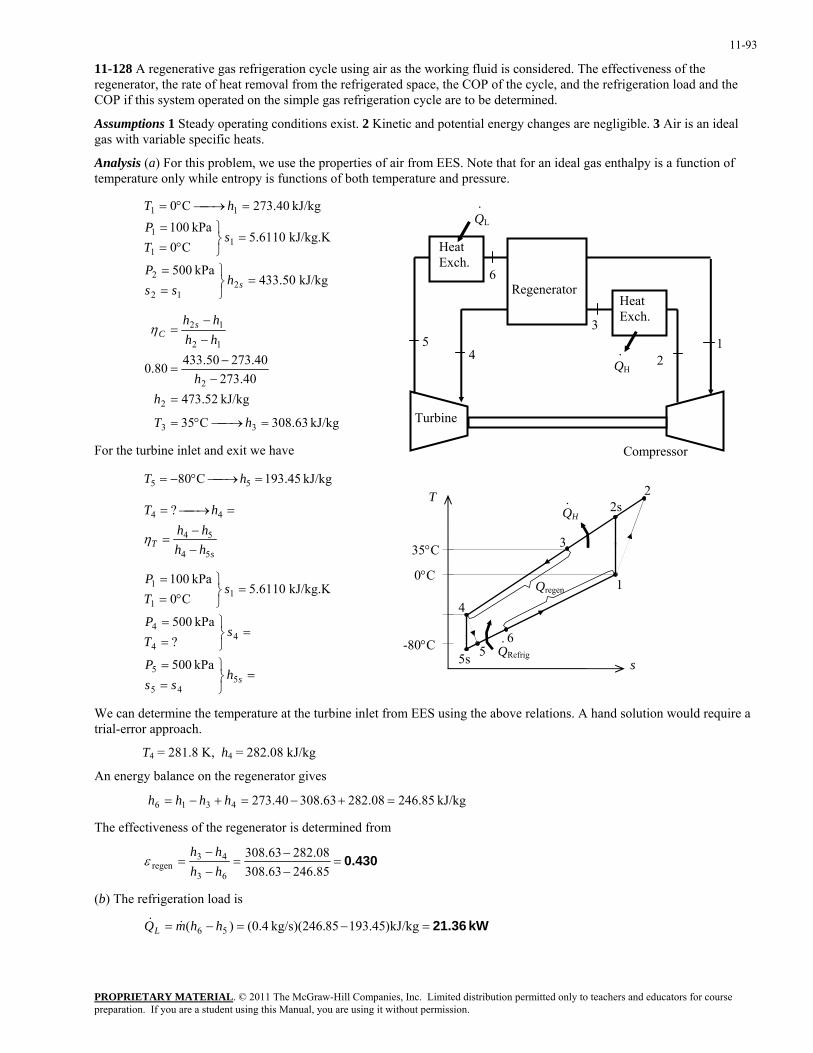
11-93
11-128 A regenerative gas refrigeration cycle using air as the working fluid is considered. The effectiveness of the regenerator, the rate of heat removal from the refrigerated space, the COP of the cycle, and the refrigeration load and the COP if this system operated on the simple gas refrigeration cycle are to be determined.
Assumptions 1 Steady operating conditions exist. 2 Kinetic and potential energy changes are negligible. 3 Air is an ideal gas with variable specific heats.
Analysis (a) For this problem, we use the properties of air from EES. Note that for an ideal gas enthalpy is a function of temperature only while entropy is functions of both temperature and pressure.
.
3
45
6
QH
Compressor
12
QL
Turbine
Heat Exch.
Heat Exch.
Regenerator
.
kJ/kg 50.433kPa 500
kJ/kg.K 6110.5C0
kPa 100kJ/kg 40.273C0
212
2
11
1
11
=⎭⎬⎫
==
=⎭⎬⎫
°==
=⎯→⎯°=
shss
P
sTP
hT
kJ/kg 63.308C35
kJ/kg 52.47340.273
40.27350.43380.0
33
2
2
12
12
=⎯→⎯°=
=−
−=
−−
=
hT
hh
hhhh s
Cη
For the turbine inlet and exit we have
kJ/kg 45.193C80 55 =⎯→⎯°−= hT
s
1
3
5s6
4
2s QH·
QRefrig·
Qregen
5
2 T
sT hh
hhhT
54
54
44 ?
−−
=
=⎯→⎯=
η
35°C
0°C
=⎭⎬⎫
==
=⎭⎬⎫
==
=⎭⎬⎫
°==
shss
P
sTP
sTP
545
5
44
4
11
1
kPa 500
?kPa 500
kJ/kg.K 6110.5C0
kPa 100
-80°C
We can determine the temperature at the turbine inlet from EES using the above relations. A hand solution would require a trial-error approach.
T4 = 281.8 K, h4 = 282.08 kJ/kg
An energy balance on the regenerator gives
kJ/kg 85.24608.28263.30840.2734316 =+−=+−= hhhh
The effectiveness of the regenerator is determined from
0.430=−−
=−−
=85.24663.30808.28263.308
63
43regen hh
hhε
(b) The refrigeration load is
kW 21.36=−=−= kJ/kg)45.19385kg/s)(246. 4.0()( 56 hhmQL &&
PROPRIETARY MATERIALpreparation. If you are a student using this Manual, you are using it without permission.
. © 2011 The McGraw-Hill Companies, Inc. Limited distribution permitted only to teachers and educators for course
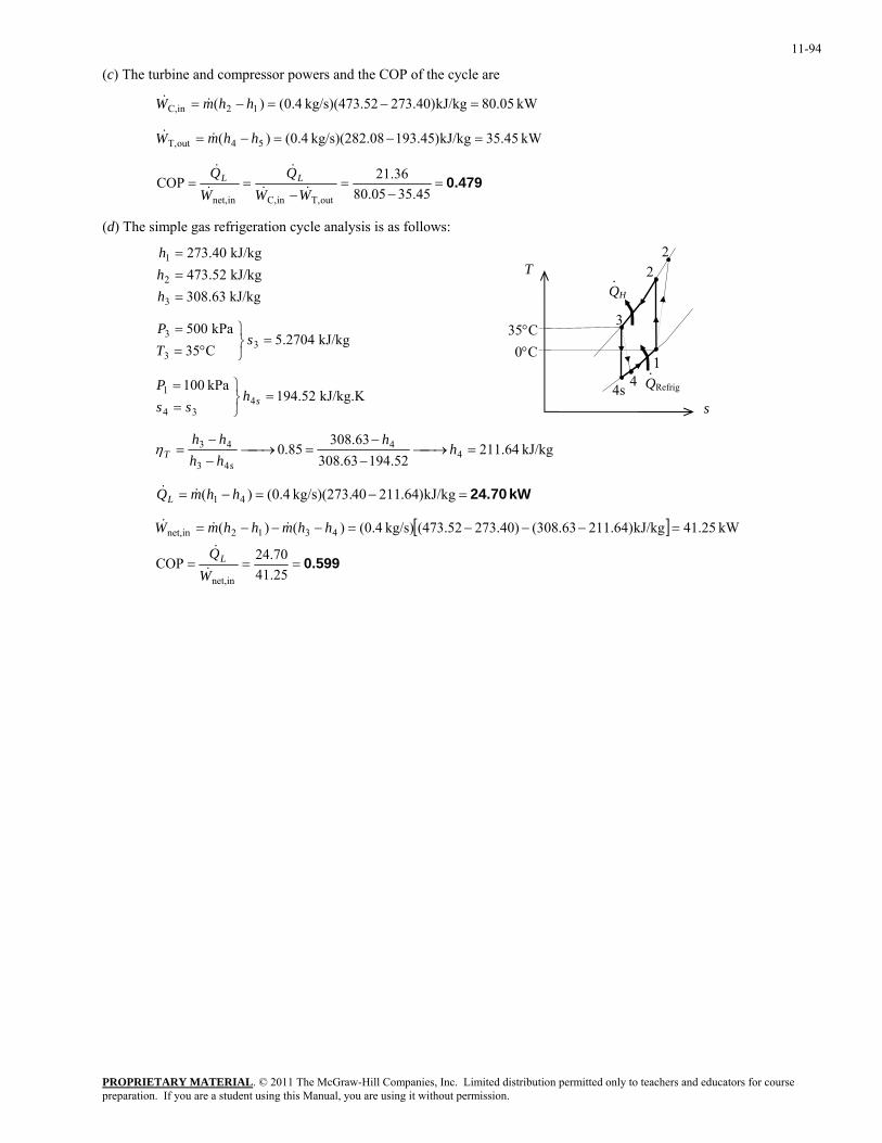
11-94
(c) The turbine and compressor powers and the COP of the cycle are
kW 05.80kJ/kg)40.27352kg/s)(473. 4.0()( 12inC, =−=−= hhmW &&
kW 45.35kJ/kg)45.19308kg/s)(282. 4.0()( 54outT, =−=−= hhmW &&
0.479=−
=−
==45.3505.80
36.21COPoutT,inC,innet, WW
QW
Q LL&&
&
&
&
(d) The simple gas refrigeration cycle analysis is as follows:
T
1
2QH
3
4s QRefrig·
2
4 1
·
0°C35°C
kJ/kg 63.308kJ/kg 52.473kJ/kg 40.273
3
2
1
===
hhh
kJ/kg 2704.5C35kPa 500
33
3 =⎭⎬⎫
°==
sTP
kJ/kg.K 52.194kPa 100
434
1 =⎭⎬⎫
==
shss
P
s
kJ/kg 64.21152.19463.308
63.30885.0 4
4
43
43 =⎯→⎯−
−=⎯→⎯
−−
= hh
hhhh
sTη
kW 24.70=−=−= kJ/kg)64.21140kg/s)(273. 4.0()( 41 hhmQL &&
[ ] kW 25.41kJ/kg)64.211(308.63)40.273(473.52kg/s) 4.0()()( 4312innet, =−−−=−−−= hhmhhmW &&&
0.599===25.4170.24COP
innet,WQL&
&
PROPRIETARY MATERIALpreparation. If you are a student using this Manual, you are using it without permission.
. © 2011 The McGraw-Hill Companies, Inc. Limited distribution permitted only to teachers and educators for course
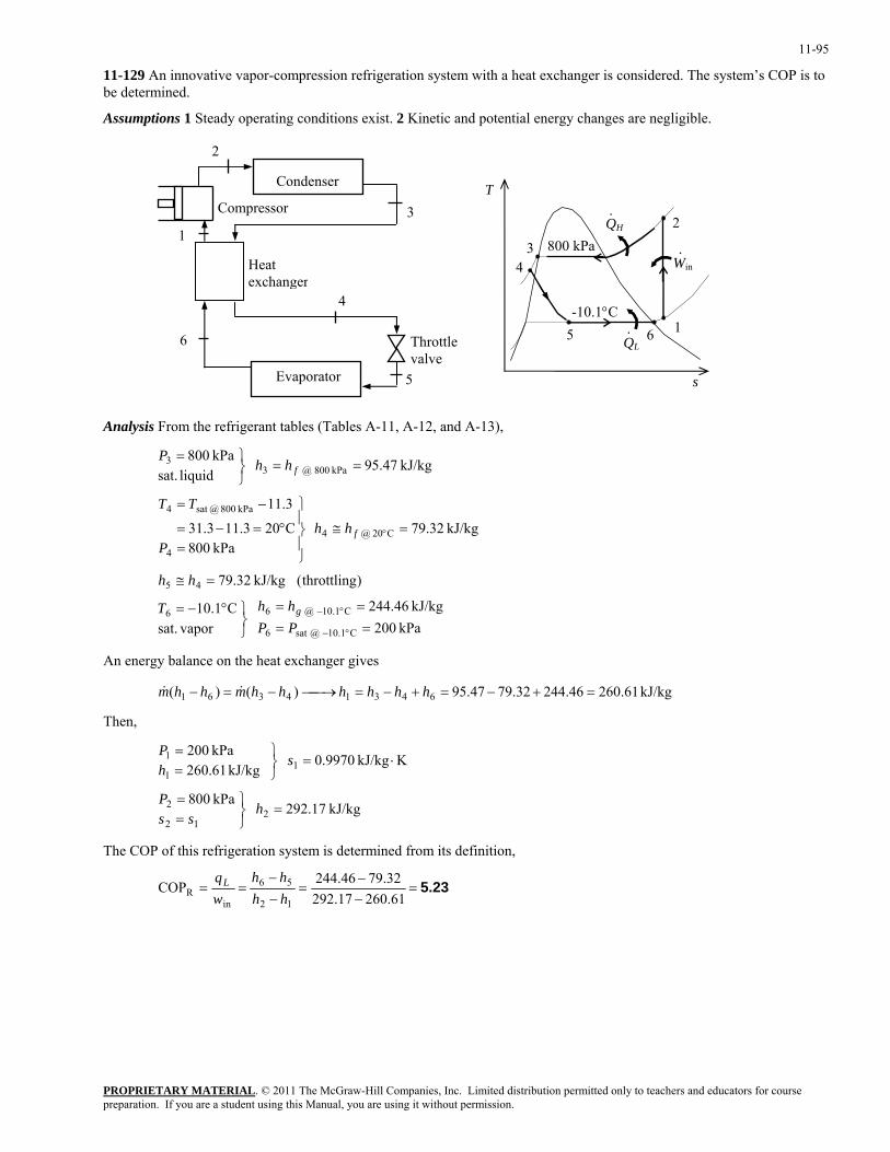
11-95
11-129 An innovative vapor-compression refrigeration system with a heat exchanger is considered. The system’s COP is to be determined.
Assumptions 1 Steady operating conditions exist. 2 Kinetic and potential energy changes are negligible.
3
4
5
6
Compressor
1
2
Heat exchanger
Condenser
Evaporator
QH
QL
-10.1°C1
2
3
5
800 kPa 4 Win
·
·
·
6
s
T
Throttle valve
Analysis From the refrigerant tables (Tables A-11, A-12, and A-13),
kPa 200kJ/kg 46.244
vapor sat.
C1.10
)throttling( kJ/kg 32.79
kJ/kg 32.79 kPa 800
C203.113.31
3.11
kJ/kg 47.95 liquid sat.kPa 800
C10.1 @sat 6
C1.10 @ 66
45
C20 @ 4
4
kPa 800 @sat 4
kPa 800 @ 33
====
⎭⎬⎫°−=
=≅
=≅⎪⎭
⎪⎬
⎫
=°=−=
−=
==⎭⎬⎫=
°−
°−
°
PPhhT
hh
hhP
TT
hhP
g
f
f
An energy balance on the heat exchanger gives
kJ/kg 61.26046.24432.7947.95)()( 64314361 =+−=+−=⎯→⎯−=− hhhhhhmhhm &&
Then,
kJ/kg 17.292 kPa 800
KkJ/kg 9970.0 kJ/kg 61.260
kPa 200
212
2
11
1
=⎭⎬⎫
==
⋅=⎭⎬⎫
==
hss
P
shP
The COP of this refrigeration system is determined from its definition,
5.23=−−
=−−
==61.26017.292
32.7946.244COP12
56
inR hh
hhwqL
PROPRIETARY MATERIALpreparation. If you are a student using this Manual, you are using it without permission.
. © 2011 The McGraw-Hill Companies, Inc. Limited distribution permitted only to teachers and educators for course
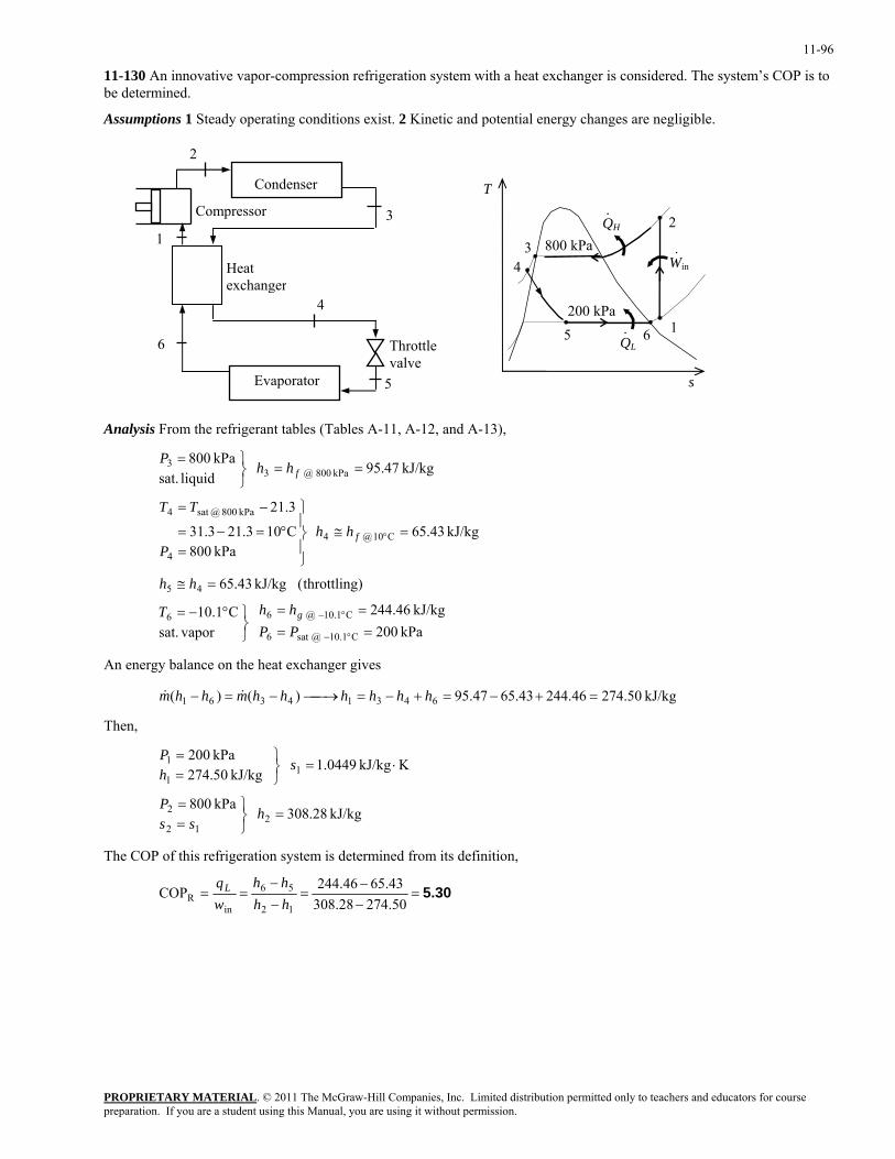
11-96
11-130 An innovative vapor-compression refrigeration system with a heat exchanger is considered. The system’s COP is to be determined.
Assumptions 1 Steady operating conditions exist. 2 Kinetic and potential energy changes are negligible.
3
4
5
6
Compressor
1
2
Heat exchanger
Condenser
Evaporator
QH
QL
200 kPa1
2
3
5
800 kPa 4 Win
·
·
·
6
s
T
Throttle valve
Analysis From the refrigerant tables (Tables A-11, A-12, and A-13),
kPa 200kJ/kg 46.244
vapor sat.
C1.10
)throttling( kJ/kg 43.65
kJ/kg 43.65 kPa 800
C103.213.31
3.21
kJ/kg 47.95 liquid sat.kPa 800
C10.1 @sat 6
C1.10 @ 66
45
C10 @ 4
4
kPa 800 @sat 4
kPa 800 @ 33
====
⎭⎬⎫°−=
=≅
=≅⎪⎭
⎪⎬
⎫
=°=−=
−=
==⎭⎬⎫=
°−
°−
°
PPhhT
hh
hhP
TT
hhP
g
f
f
An energy balance on the heat exchanger gives
kJ/kg 50.27446.24443.6547.95)()( 64314361 =+−=+−=⎯→⎯−=− hhhhhhmhhm &&
Then,
kJ/kg 28.308 kPa 800
KkJ/kg 0449.1 kJ/kg 50.274
kPa 200
212
2
11
1
=⎭⎬⎫
==
⋅=⎭⎬⎫
==
hss
P
shP
The COP of this refrigeration system is determined from its definition,
5.30=−−
=−−
==50.27428.30843.6546.244COP
12
56
inR hh
hhwqL
PROPRIETARY MATERIALpreparation. If you are a student using this Manual, you are using it without permission.
. © 2011 The McGraw-Hill Companies, Inc. Limited distribution permitted only to teachers and educators for course
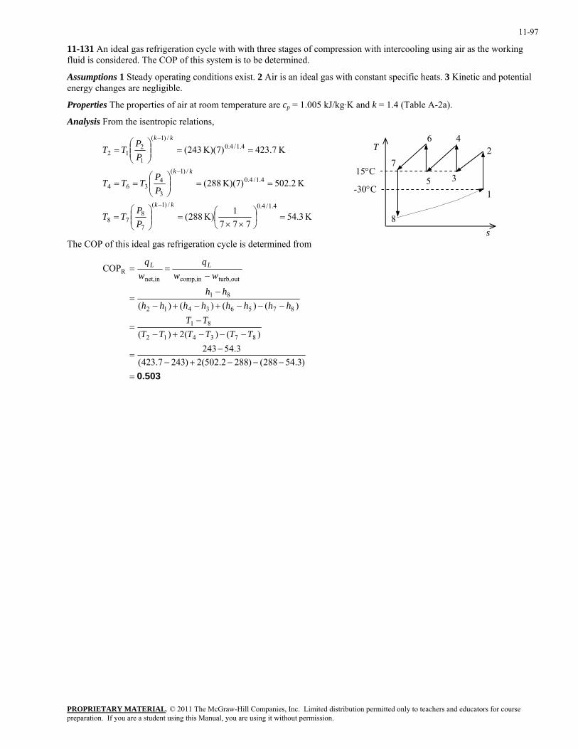
11-97
11-131 An ideal gas refrigeration cycle with with three stages of compression with intercooling using air as the working fluid is considered. The COP of this system is to be determined.
Assumptions 1 Steady operating conditions exist. 2 Air is an ideal gas with constant specific heats. 3 Kinetic and potential energy changes are negligible.
Properties The properties of air at room temperature are cp = 1.005 kJ/kg·K and k = 1.4 (Table A-2a).
Analysis From the isentropic relations,
3
4
8
7
5
6 2
1
s
K 3.54777
1K) 288(
K 2.502K)(7) 288(
K 7.423K)(7) 243(
4.1/4.0/)1(
7
878
4.1/4.0/)1(
3
4364
4.1/4.0/)1(
1
212
=⎟⎠⎞
⎜⎝⎛
××=⎟⎟
⎠
⎞⎜⎜⎝
⎛=
==⎟⎟⎠
⎞⎜⎜⎝
⎛==
==⎟⎟⎠
⎞⎜⎜⎝
⎛=
−
−
−
kk
kk
kk
PP
TT
PP
TTT
PP
TT
T
15°C
-30°C
The COP of this ideal gas refrigeration cycle is determined from
0.503=−−−+−
−=
−−−+−−
=
−−−+−+−−
=
−==
)3.54288()2882.502(2)2437.423(3.54243
)()(2)(
)()()()(
COP
873412
81
87563412
81
outturb,incomp,innet,R
TTTTTTTT
hhhhhhhhhh
wwq
wq LL
PROPRIETARY MATERIALpreparation. If you are a student using this Manual, you are using it without permission.
. © 2011 The McGraw-Hill Companies, Inc. Limited distribution permitted only to teachers and educators for course

11-98
11-132 A vortex tube receives compressed air at 500 kPa and 300 K, and supplies 25 percent of it as cold air and the rest as hot air. The COP of the vortex tube is to be compared to that of a reversed Brayton cycle for the same pressure ratio; the exit temperature of the hot fluid stream and the COP are to be determined; and it is to be shown if this process violates the second law.
Assumptions 1 The vortex tube is adiabatic. 2 Air is an ideal gas with constant specific heats at room temperature. 3 Steady operating conditions exist.
Properties The gas constant of air is 0.287 kJ/kg.K (Table A-1). The specific heat of air at room temperature is cp = 1.005 kJ/kg.K (Table A-2). The enthalpy of air at absolute temperature T can be expressed in terms of specific heats as h = cpT.
Analysis (a) The COP of the vortex tube is much lower than the COP of a reversed Brayton cycle of the same pressure ratio since the vortex tube involves vortices, which are highly irreversible. Owing to this irreversibility, the minimum temperature that can be obtained by the vortex tube is not as low as the one that can be obtained by the revered Brayton cycle.
(b) We take the vortex tube as the system. This is a steady flow system with one inlet and two exits, and it involves no heat or work interactions. Then the steady-flow energy balance equation for this system for a unit mass flow rate at the inlet can be expressed as
& &E Ein out=( &m1 kg / s)= 1
Warm air Cold air
Compressed air
2 3
1
321
332211
332211
75.025.01 TcTcTc
TcmTcmTcmhmhmhm
ppp
ppp
+=
+=+=
&&&
&&&
Canceling cp and solving for T3 gives
K 307.3=×−
=−
=75.0
27825.030075.025.0 21
3TT
T
Therefore, the hot air stream will leave the vortex tube at an average temperature of 307.3 K.
(c) The entropy balance for this steady flow system can be expressed as with one inlet and two exits,
and it involves no heat or work interactions. Then the steady-flow entropy balance equation for this system for a unit mass flow rate at the inlet ( can be expressed
& & &S S Sin out gen− + = 0
&m1 kg / s)= 1
⎟⎟⎠
⎞⎜⎜⎝
⎛−+⎟⎟
⎠
⎞⎜⎜⎝
⎛−=
−+−=−+−=
+−+=−+=
−=
1
3
1
3
1
2
1
2
1312
133122
1323322113322
inoutgen
lnln75.0lnln25.0
)(75.0)(25.0)()(
)(
PP
RTT
cPP
RTT
c
ssssssmssm
smmsmsmsmsmsm
SSS
pp
&&
&&&&&&&
&&&
Substituting the known quantities, the rate of entropy generation is determined to be
0>kW/K 461.0kPa 500kPa 100ln kJ/kg.K) 287.0(
K 300K 3.307ln kJ/kg.K) 005.1(75.0
kPa 500kPa 100ln kJ/kg.K) 287.0(
K 300K 278ln kJ/kg.K) 005.1(25.0gen
=
⎟⎠⎞
⎜⎝⎛ −+
⎟⎠⎞
⎜⎝⎛ −=S&
which is a positive quantity. Therefore, this process satisfies the 2nd law of thermodynamics.
(d) For a unit mass flow rate at the inlet ( &m1 kg / s)= 1 , the cooling rate and the power input to the compressor are determined to
kW 5.53=278)K-00kJ/kg.K)(3 5kg/s)(1.00 25.0(
)()( c1c1cooling
=
−=−= TTcmhhmQ pcc &&&
PROPRIETARY MATERIALpreparation. If you are a student using this Manual, you are using it without permission.
. © 2011 The McGraw-Hill Companies, Inc. Limited distribution permitted only to teachers and educators for course
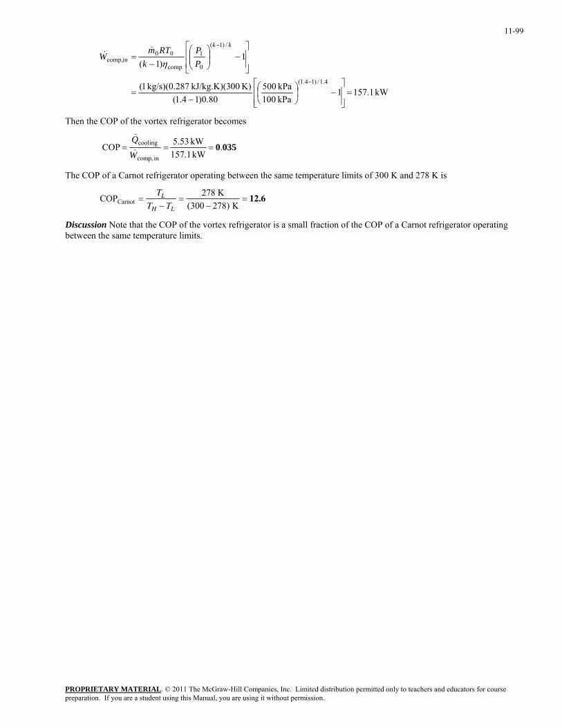
11-99
kW 1.1571kPa 100kPa 500
80.0)14.1(K) 00kJ/kg.K)(3 7kg/s)(0.28 1(
1)1(
4.1/)14.1(
/)1(
0
1
comp
00incomp,
=⎥⎥⎦
⎤
⎢⎢⎣
⎡−⎟
⎠⎞
⎜⎝⎛
−=
⎥⎥
⎦
⎤
⎢⎢
⎣
⎡−⎟⎟
⎠
⎞⎜⎜⎝
⎛−
=
−
− kk
PP
kRTm
Wη
&&
Then the COP of the vortex refrigerator becomes
0350.kW 1.157kW 5.53COP
in comp,
cooling ===W
Q&
&
The COP of a Carnot refrigerator operating between the same temperature limits of 300 K and 278 K is
COP 278 K KCarnot =
−=
−=
T
T TL
H L ( )300 27812.6
Discussion Note that the COP of the vortex refrigerator is a small fraction of the COP of a Carnot refrigerator operating between the same temperature limits.
PROPRIETARY MATERIALpreparation. If you are a student using this Manual, you are using it without permission.
. © 2011 The McGraw-Hill Companies, Inc. Limited distribution permitted only to teachers and educators for course
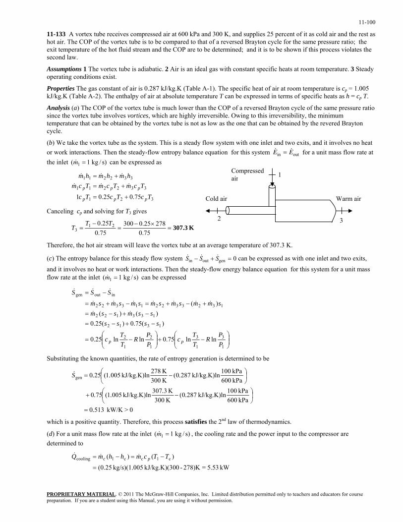
11-100
11-133 A vortex tube receives compressed air at 600 kPa and 300 K, and supplies 25 percent of it as cold air and the rest as hot air. The COP of the vortex tube is to be compared to that of a reversed Brayton cycle for the same pressure ratio; the exit temperature of the hot fluid stream and the COP are to be determined; and it is to be shown if this process violates the second law.
Assumptions 1 The vortex tube is adiabatic. 2 Air is an ideal gas with constant specific heats at room temperature. 3 Steady operating conditions exist.
Properties The gas constant of air is 0.287 kJ/kg.K (Table A-1). The specific heat of air at room temperature is cp = 1.005 kJ/kg.K (Table A-2). The enthalpy of air at absolute temperature T can be expressed in terms of specific heats as h = cp T.
Analysis (a) The COP of the vortex tube is much lower than the COP of a reversed Brayton cycle of the same pressure ratio since the vortex tube involves vortices, which are highly irreversible. Owing to this irreversibility, the minimum temperature that can be obtained by the vortex tube is not as low as the one that can be obtained by the revered Brayton cycle.
(b) We take the vortex tube as the system. This is a steady flow system with one inlet and two exits, and it involves no heat or work interactions. Then the steady-flow entropy balance equation for this system for a unit mass flow rate at the inlet can be expressed as
& &E Ein out=( &m1 kg / s)= 1
Warm air Cold air
Compressed air
2 3
1
321
332211
332211
75.025.01 TcTcTc
TcmTcmTcmhmhmhm
ppp
ppp
+=
+=+=
&&&
&&&
Canceling cp and solving for T3 gives
K 307.3=×−
=−
=75.0
27825.030075.025.0 21
3TT
T
Therefore, the hot air stream will leave the vortex tube at an average temperature of 307.3 K.
(c) The entropy balance for this steady flow system can be expressed as with one inlet and two exits,
and it involves no heat or work interactions. Then the steady-flow energy balance equation for this system for a unit mass flow rate at the inlet ( can be expressed
& & &S S Sin out gen− + = 0
&m1 kg / s)= 1
⎟⎟⎠
⎞⎜⎜⎝
⎛−+⎟⎟
⎠
⎞⎜⎜⎝
⎛−=
−+−=−+−=
+−+=−+=
−=
1
3
1
3
1
2
1
2
1312
133122
1323322113322
inoutgen
lnln75.0lnln25.0
)(75.0)(25.0)()(
)(
PP
RTT
cPP
RTT
c
ssssssmssm
smmsmsmsmsmsm
SSS
pp
&&
&&&&&&&
&&&
Substituting the known quantities, the rate of entropy generation is determined to be
0>kW/K 5130kPa 600kPa 100kJ/kg.K)ln 2870(
K300 K3307kJ/kg.K)ln 0051(750
kPa 600kPa 100kJ/kg.K)ln 2870(
K300 K278kJ/kg.K)ln 0051(250gen
.
....
...S
=
⎟⎠⎞
⎜⎝⎛ −+
⎟⎠⎞
⎜⎝⎛ −=&
which is a positive quantity. Therefore, this process satisfies the 2nd law of thermodynamics.
(d) For a unit mass flow rate at the inlet ( &m1 kg / s)= 1 , the cooling rate and the power input to the compressor are determined to
kW5.53=278)K-00kJ/kg.K)(3 5kg/s)(1.00 25.0(
)()( c1c1cooling
=
−=−= TTcmhhmQ pcc &&&
PROPRIETARY MATERIALpreparation. If you are a student using this Manual, you are using it without permission.
. © 2011 The McGraw-Hill Companies, Inc. Limited distribution permitted only to teachers and educators for course
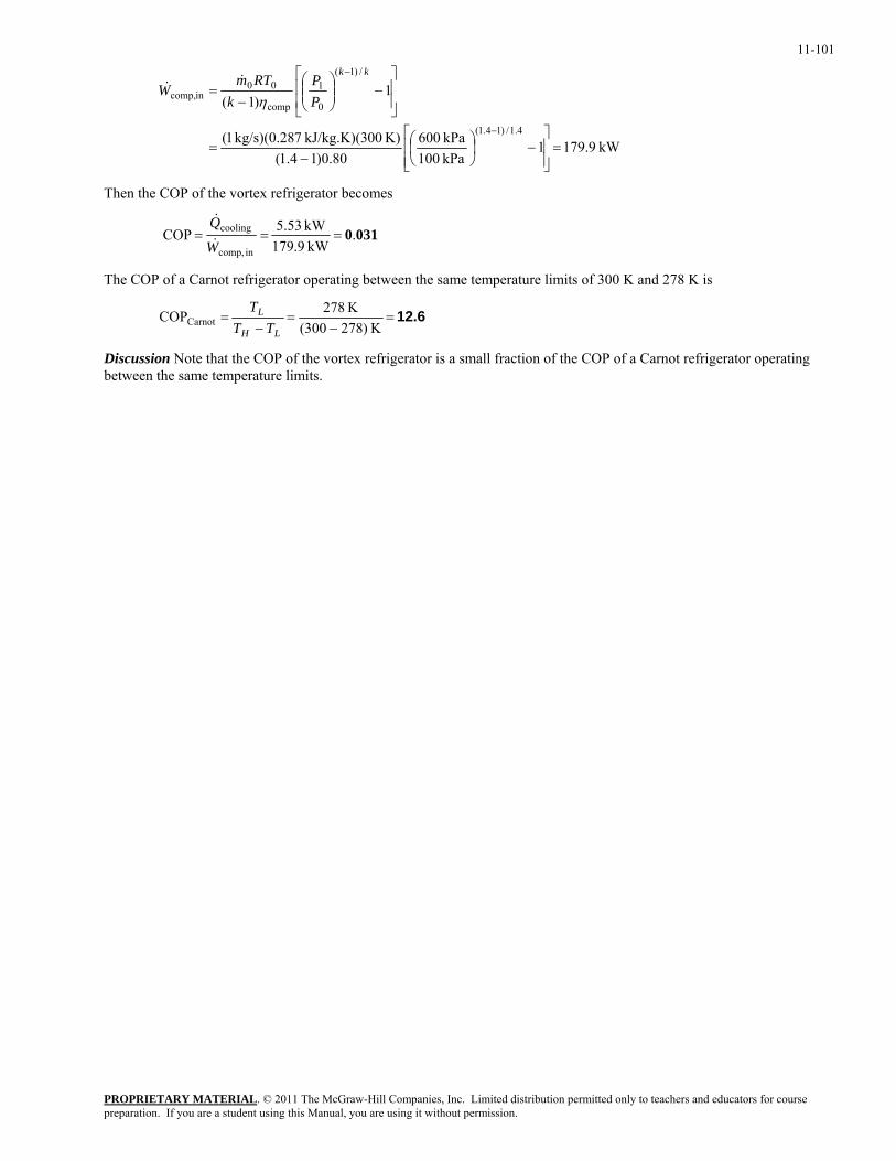
11-101
kW 9.1791kPa 100kPa 600
80.0)14.1(K) 00kJ/kg.K)(3 7kg/s)(0.28 1(
1)1(
4.1/)14.1(
/)1(
0
1
comp
00incomp,
=⎥⎥⎦
⎤
⎢⎢⎣
⎡−⎟
⎠⎞
⎜⎝⎛
−=
⎥⎥
⎦
⎤
⎢⎢
⎣
⎡−⎟⎟
⎠
⎞⎜⎜⎝
⎛−
=
−
− kk
PP
kRTm
Wη
&&
Then the COP of the vortex refrigerator becomes
0310.kW 9.179kW 5.53COP
in comp,
cooling ===W
Q&
&
The COP of a Carnot refrigerator operating between the same temperature limits of 300 K and 278 K is
12.6=−
=−
=K )278300(
K 278COPCarnotLH
L
TTT
Discussion Note that the COP of the vortex refrigerator is a small fraction of the COP of a Carnot refrigerator operating between the same temperature limits.
PROPRIETARY MATERIALpreparation. If you are a student using this Manual, you are using it without permission.
. © 2011 The McGraw-Hill Companies, Inc. Limited distribution permitted only to teachers and educators for course
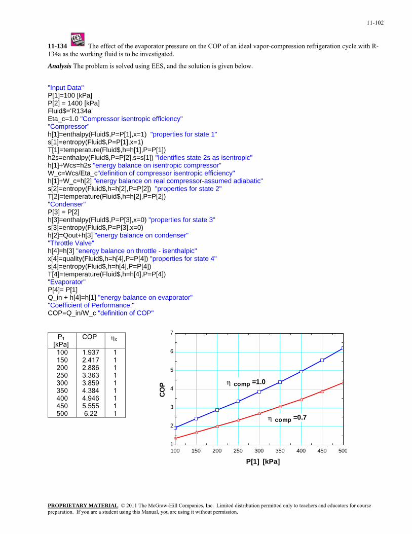
11-102
11-134 The effect of the evaporator pressure on the COP of an ideal vapor-compression refrigeration cycle with R-134a as the working fluid is to be investigated.
Analysis The problem is solved using EES, and the solution is given below.
"Input Data" P[1]=100 [kPa] P[2] = 1400 [kPa] Fluid$='R134a' Eta_c=1.0 "Compressor isentropic efficiency" "Compressor" h[1]=enthalpy(Fluid$,P=P[1],x=1) "properties for state 1" s[1]=entropy(Fluid$,P=P[1],x=1) T[1]=temperature(Fluid$,h=h[1],P=P[1]) h2s=enthalpy(Fluid$,P=P[2],s=s[1]) "Identifies state 2s as isentropic" h[1]+Wcs=h2s "energy balance on isentropic compressor" W_c=Wcs/Eta_c"definition of compressor isentropic efficiency" h[1]+W_c=h[2] "energy balance on real compressor-assumed adiabatic" s[2]=entropy(Fluid$,h=h[2],P=P[2]) "properties for state 2" T[2]=temperature(Fluid$,h=h[2],P=P[2]) "Condenser" P[3] = P[2] h[3]=enthalpy(Fluid$,P=P[3],x=0) "properties for state 3" s[3]=entropy(Fluid$,P=P[3],x=0) h[2]=Qout+h[3] "energy balance on condenser" "Throttle Valve" h[4]=h[3] "energy balance on throttle - isenthalpic" x[4]=quality(Fluid$,h=h[4],P=P[4]) "properties for state 4" s[4]=entropy(Fluid$,h=h[4],P=P[4]) T[4]=temperature(Fluid$,h=h[4],P=P[4]) "Evaporator" P[4]= P[1] Q_in + h[4]=h[1] "energy balance on evaporator" "Coefficient of Performance:" COP=Q_in/W_c "definition of COP"
100 150 200 250 300 350 400 450 5001
2
3
4
5
6
7
P[1] [kPa]
COP
η comp =0.7
η comp =1.0
P1 [kPa]
COP ηc
100 150 200 250 300 350 400 450 500
1.937 2.417 2.886 3.363 3.859 4.384 4.946 5.555 6.22
1 1 1 1 1 1 1 1 1
PROPRIETARY MATERIALpreparation. If you are a student using this Manual, you are using it without permission.
. © 2011 The McGraw-Hill Companies, Inc. Limited distribution permitted only to teachers and educators for course
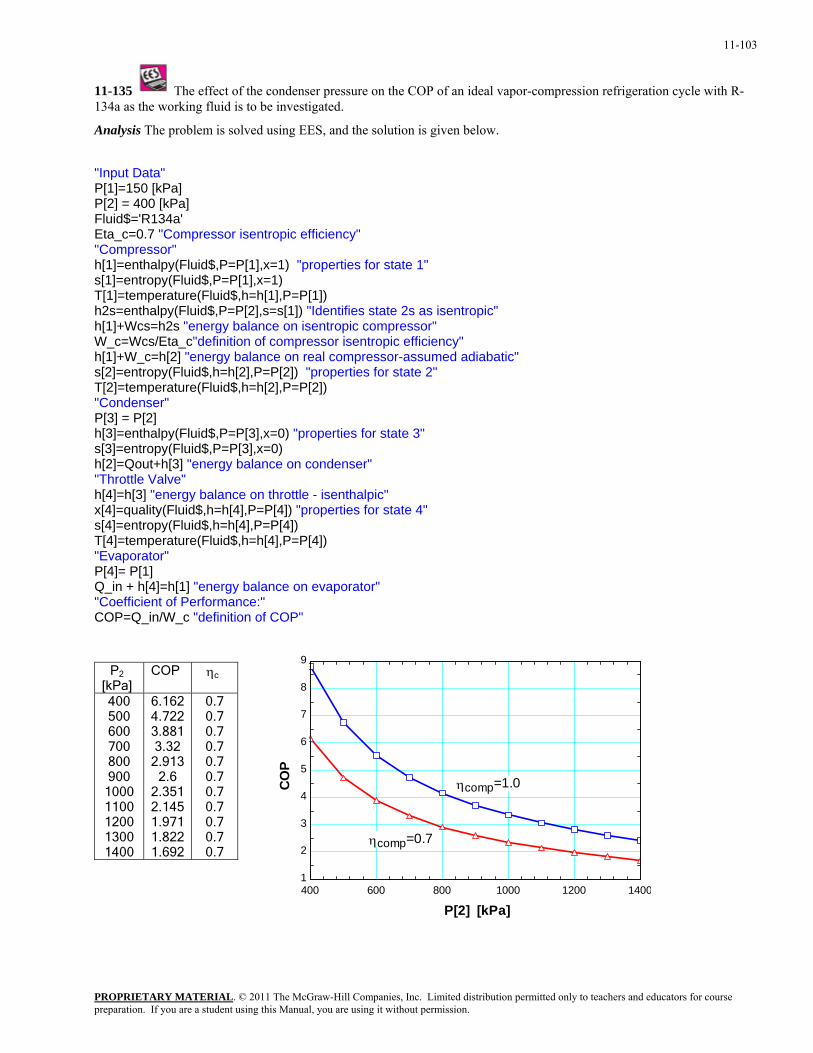
11-103
11-135 The effect of the condenser pressure on the COP of an ideal vapor-compression refrigeration cycle with R-134a as the working fluid is to be investigated.
Analysis The problem is solved using EES, and the solution is given below.
"Input Data" P[1]=150 [kPa] P[2] = 400 [kPa] Fluid$='R134a' Eta_c=0.7 "Compressor isentropic efficiency" "Compressor" h[1]=enthalpy(Fluid$,P=P[1],x=1) "properties for state 1" s[1]=entropy(Fluid$,P=P[1],x=1) T[1]=temperature(Fluid$,h=h[1],P=P[1]) h2s=enthalpy(Fluid$,P=P[2],s=s[1]) "Identifies state 2s as isentropic" h[1]+Wcs=h2s "energy balance on isentropic compressor" W_c=Wcs/Eta_c"definition of compressor isentropic efficiency" h[1]+W_c=h[2] "energy balance on real compressor-assumed adiabatic" s[2]=entropy(Fluid$,h=h[2],P=P[2]) "properties for state 2" T[2]=temperature(Fluid$,h=h[2],P=P[2]) "Condenser" P[3] = P[2] h[3]=enthalpy(Fluid$,P=P[3],x=0) "properties for state 3" s[3]=entropy(Fluid$,P=P[3],x=0) h[2]=Qout+h[3] "energy balance on condenser" "Throttle Valve" h[4]=h[3] "energy balance on throttle - isenthalpic" x[4]=quality(Fluid$,h=h[4],P=P[4]) "properties for state 4" s[4]=entropy(Fluid$,h=h[4],P=P[4]) T[4]=temperature(Fluid$,h=h[4],P=P[4]) "Evaporator" P[4]= P[1] Q_in + h[4]=h[1] "energy balance on evaporator" "Coefficient of Performance:" COP=Q_in/W_c "definition of COP"
400 600 800 1000 1200 14001
2
3
4
5
6
7
8
9
P[2] [kPa]
COP
ηcomp=0.7
ηcomp=1.0
P2 [kPa]
COP ηc
400 500 600 700 800 900
1000 1100 1200 1300 1400
6.162 4.722 3.881 3.32
2.913 2.6
2.351 2.145 1.971 1.822 1.692
0.7 0.7 0.7 0.7 0.7 0.7 0.7 0.7 0.7 0.7 0.7
PROPRIETARY MATERIALpreparation. If you are a student using this Manual, you are using it without permission.
. © 2011 The McGraw-Hill Companies, Inc. Limited distribution permitted only to teachers and educators for course
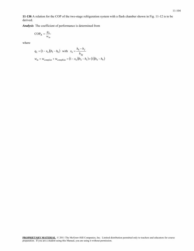
11-104
11-136 A relation for the COP of the two-stage refrigeration system with a flash chamber shown in Fig. 11-12 is to be derived.
Analysis The coefficient of performance is determined from
COPRin
=q
wL
where
( )( )
( )( ) ( )( 94126incompII,incompI,in
66816
11
with1
hhhhxwww
hhh
xhhxqfg
fL
−+−−=+=
−=−−=
)
PROPRIETARY MATERIALpreparation. If you are a student using this Manual, you are using it without permission.
. © 2011 The McGraw-Hill Companies, Inc. Limited distribution permitted only to teachers and educators for course
11-105
Fundamentals of Engineering (FE) Exam Problems
11-137 Consider a heat pump that operates on the reversed Carnot cycle with R-134a as the working fluid executed under the saturation dome between the pressure limits of 140 kPa and 800 kPa. R-134a changes from saturated vapor to saturated liquid during the heat rejection process. The net work input for this cycle is
(a) 28 kJ/kg (b) 34 kJ/kg (c) 49 kJ/kg (d) 144 kJ/kg (e) 275 kJ/kg
Answer (a) 28 kJ/kg
Solution Solved by EES Software. Solutions can be verified by copying-and-pasting the following lines on a blank EES screen. (Similar problems and their solutions can be obtained easily by modifying numerical values).
P1=800 "kPa" P2=140 "kPa" h_fg=ENTHALPY(R134a,x=1,P=P1)-ENTHALPY(R134a,x=0,P=P1) TH=TEMPERATURE(R134a,x=0,P=P1)+273 TL=TEMPERATURE(R134a,x=0,P=P2)+273 q_H=h_fg COP=TH/(TH-TL) w_net=q_H/COP "Some Wrong Solutions with Common Mistakes:" W1_work = q_H/COP1; COP1=TL/(TH-TL) "Using COP of regrigerator" W2_work = q_H/COP2; COP2=(TH-273)/(TH-TL) "Using C instead of K" W3_work = h_fg3/COP; h_fg3= ENTHALPY(R134a,x=1,P=P2)-ENTHALPY(R134a,x=0,P=P2) "Using h_fg at P2" W4_work = q_H*TL/TH "Using the wrong relation"
11-138 A refrigerator removes heat from a refrigerated space at 0°C at a rate of 2.2 kJ/s and rejects it to an environment at 20°C. The minimum required power input is
(a) 89 W (b) 150 W (c) 161 W (d) 557 W (e) 2200 W
Answer (c) 161 W
Solution Solved by EES Software. Solutions can be verified by copying-and-pasting the following lines on a blank EES screen. (Similar problems and their solutions can be obtained easily by modifying numerical values).
TH=20+273 TL=0+273 Q_L=2.2 "kJ/s" COP_max=TL/(TH-TL) w_min=Q_L/COP_max "Some Wrong Solutions with Common Mistakes:" W1_work = Q_L/COP1; COP1=TH/(TH-TL) "Using COP of heat pump" W2_work = Q_L/COP2; COP2=(TH-273)/(TH-TL) "Using C instead of K" W3_work = Q_L*TL/TH "Using the wrong relation" W4_work = Q_L "Taking the rate of refrigeration as power input"
PROPRIETARY MATERIALpreparation. If you are a student using this Manual, you are using it without permission.
. © 2011 The McGraw-Hill Companies, Inc. Limited distribution permitted only to teachers and educators for course
11-106
11-139 A refrigerator operates on the ideal vapor compression refrigeration cycle with R-134a as the working fluid between the pressure limits of 120 kPa and 800 kPa. If the rate of heat removal from the refrigerated space is 32 kJ/s, the mass flow rate of the refrigerant is
(a) 0.19 kg/s (b) 0.15 kg/s (c) 0.23 kg/s (d) 0.28 kg/s (e) 0.81 kg/s
Answer (c) 0.23 kg/s
Solution Solved by EES Software. Solutions can be verified by copying-and-pasting the following lines on a blank EES screen. (Similar problems and their solutions can be obtained easily by modifying numerical values).
P1=120 "kPa" P2=800 "kPa" P3=P2 P4=P1 s2=s1 Q_refrig=32 "kJ/s" m=Q_refrig/(h1-h4) h1=ENTHALPY(R134a,x=1,P=P1) s1=ENTROPY(R134a,x=1,P=P1) h2=ENTHALPY(R134a,s=s2,P=P2) h3=ENTHALPY(R134a,x=0,P=P3) h4=h3 "Some Wrong Solutions with Common Mistakes:" W1_mass = Q_refrig/(h2-h1) "Using wrong enthalpies, for W_in" W2_mass = Q_refrig/(h2-h3) "Using wrong enthalpies, for Q_H" W3_mass = Q_refrig/(h1-h44); h44=ENTHALPY(R134a,x=0,P=P4) "Using wrong enthalpy h4 (at P4)" W4_mass = Q_refrig/h_fg; h_fg=ENTHALPY(R134a,x=1,P=P2) - ENTHALPY(R134a,x=0,P=P2) "Using h_fg at P2"
PROPRIETARY MATERIALpreparation. If you are a student using this Manual, you are using it without permission.
. © 2011 The McGraw-Hill Companies, Inc. Limited distribution permitted only to teachers and educators for course
11-107
11-140 A heat pump operates on the ideal vapor compression refrigeration cycle with R-134a as the working fluid between the pressure limits of 0.32 MPa and 1.2 MPa. If the mass flow rate of the refrigerant is 0.193 kg/s, the rate of heat supply by the heat pump to the heated space is
(a) 3.3 kW (b) 23 kW (c) 26 kW (d) 31 kW (e) 45 kW
Answer (d) 31 kW
Solution Solved by EES Software. Solutions can be verified by copying-and-pasting the following lines on a blank EES screen. (Similar problems and their solutions can be obtained easily by modifying numerical values).
P1=320 "kPa" P2=1200 "kPa" P3=P2 P4=P1 s2=s1 m=0.193 "kg/s" Q_supply=m*(h2-h3) "kJ/s" h1=ENTHALPY(R134a,x=1,P=P1) s1=ENTROPY(R134a,x=1,P=P1) h2=ENTHALPY(R134a,s=s2,P=P2) h3=ENTHALPY(R134a,x=0,P=P3) h4=h3 "Some Wrong Solutions with Common Mistakes:" W1_Qh = m*(h2-h1) "Using wrong enthalpies, for W_in" W2_Qh = m*(h1-h4) "Using wrong enthalpies, for Q_L" W3_Qh = m*(h22-h4); h22=ENTHALPY(R134a,x=1,P=P2) "Using wrong enthalpy h2 (hg at P2)" W4_Qh = m*h_fg; h_fg=ENTHALPY(R134a,x=1,P=P1) - ENTHALPY(R134a,x=0,P=P1) "Using h_fg at P1"
PROPRIETARY MATERIALpreparation. If you are a student using this Manual, you are using it without permission.
. © 2011 The McGraw-Hill Companies, Inc. Limited distribution permitted only to teachers and educators for course
11-108
11-141 An ideal vapor compression refrigeration cycle with R-134a as the working fluid operates between the pressure limits of 120 kPa and 700 kPa. The mass fraction of the refrigerant that is in the liquid phase at the inlet of the evaporator is
(a) 0.69 (b) 0.63 (c) 0.58 (d) 0.43 (e) 0.35
Answer (a) 0.69
Solution Solved by EES Software. Solutions can be verified by copying-and-pasting the following lines on a blank EES screen. (Similar problems and their solutions can be obtained easily by modifying numerical values).
P1=120 "kPa" P2=700 "kPa" P3=P2 P4=P1 h1=ENTHALPY(R134a,x=1,P=P1) h3=ENTHALPY(R134a,x=0,P=P3) h4=h3 x4=QUALITY(R134a,h=h4,P=P4) liquid=1-x4 "Some Wrong Solutions with Common Mistakes:" W1_liquid = x4 "Taking quality as liquid content" W2_liquid = 0 "Assuming superheated vapor" W3_liquid = 1-x4s; x4s=QUALITY(R134a,s=s3,P=P4) "Assuming isentropic expansion" s3=ENTROPY(R134a,x=0,P=P3)
PROPRIETARY MATERIALpreparation. If you are a student using this Manual, you are using it without permission.
. © 2011 The McGraw-Hill Companies, Inc. Limited distribution permitted only to teachers and educators for course
11-109
11-142 Consider a heat pump that operates on the ideal vapor compression refrigeration cycle with R-134a as the working fluid between the pressure limits of 0.32 MPa and 1.2 MPa. The coefficient of performance of this heat pump is
(a) 0.17 (b) 1.2 (c) 3.1 (d) 4.9 (e) 5.9
Answer (e) 5.9
Solution Solved by EES Software. Solutions can be verified by copying-and-pasting the following lines on a blank EES screen. (Similar problems and their solutions can be obtained easily by modifying numerical values).
P1=320 "kPa" P2=1200 "kPa" P3=P2 P4=P1 s2=s1 h1=ENTHALPY(R134a,x=1,P=P1) s1=ENTROPY(R134a,x=1,P=P1) h2=ENTHALPY(R134a,s=s2,P=P2) h3=ENTHALPY(R134a,x=0,P=P3) h4=h3 COP_HP=qH/Win Win=h2-h1 qH=h2-h3 "Some Wrong Solutions with Common Mistakes:" W1_COP = (h1-h4)/(h2-h1) "COP of refrigerator" W2_COP = (h1-h4)/(h2-h3) "Using wrong enthalpies, QL/QH" W3_COP = (h22-h3)/(h22-h1); h22=ENTHALPY(R134a,x=1,P=P2) "Using wrong enthalpy h2 (hg at P2)"
11-143 An ideal gas refrigeration cycle using air as the working fluid operates between the pressure limits of 80 kPa and 280 kPa. Air is cooled to 35°C before entering the turbine. The lowest temperature of this cycle is
(a) –58°C (b) -26°C (c) 0°C (d) 11°C (e) 24°C
Answer (a) –58°C
Solution Solved by EES Software. Solutions can be verified by copying-and-pasting the following lines on a blank EES screen. (Similar problems and their solutions can be obtained easily by modifying numerical values).
k=1.4 P1= 80 "kPa" P2=280 "kPa" T3=35+273 "K" "Mimimum temperature is the turbine exit temperature" T4=T3*(P1/P2)^((k-1)/k) - 273 "Some Wrong Solutions with Common Mistakes:" W1_Tmin = (T3-273)*(P1/P2)^((k-1)/k) "Using C instead of K" W2_Tmin = T3*(P1/P2)^((k-1)) - 273 "Using wrong exponent" W3_Tmin = T3*(P1/P2)^k - 273 "Using wrong exponent"
PROPRIETARY MATERIALpreparation. If you are a student using this Manual, you are using it without permission.
. © 2011 The McGraw-Hill Companies, Inc. Limited distribution permitted only to teachers and educators for course
11-110
11-144 Consider an ideal gas refrigeration cycle using helium as the working fluid. Helium enters the compressor at 100 kPa and 17°C and is compressed to 400 kPa. Helium is then cooled to 20°C before it enters the turbine. For a mass flow rate of 0.2 kg/s, the net power input required is
(a) 28.3 kW (b) 40.5 kW (c) 64.7 kW (d) 93.7 kW (e) 113 kW
Answer (d) 93.7 kW
Solution Solved by EES Software. Solutions can be verified by copying-and-pasting the following lines on a blank EES screen. (Similar problems and their solutions can be obtained easily by modifying numerical values).
k=1.667 Cp=5.1926 "kJ/kg.K" P1= 100 "kPa" T1=17+273 "K" P2=400 "kPa" T3=20+273 "K" m=0.2 "kg/s" "Mimimum temperature is the turbine exit temperature" T2=T1*(P2/P1)^((k-1)/k) T4=T3*(P1/P2)^((k-1)/k) W_netin=m*Cp*((T2-T1)-(T3-T4)) "Some Wrong Solutions with Common Mistakes:" W1_Win = m*Cp*((T22-T1)-(T3-T44)); T22=T1*P2/P1; T44=T3*P1/P2 "Using wrong relations for temps" W2_Win = m*Cp*(T2-T1) "Ignoring turbine work" W3_Win=m*1.005*((T2B-T1)-(T3-T4B)); T2B=T1*(P2/P1)^((kB-1)/kB); T4B=T3*(P1/P2)^((kB-1)/kB); kB=1.4 "Using air properties" W4_Win=m*Cp*((T2A-(T1-273))-(T3-273-T4A)); T2A=(T1-273)*(P2/P1)^((k-1)/k); T4A=(T3-273)*(P1/P2)^((k-1)/k) "Using C instead of K"
PROPRIETARY MATERIALpreparation. If you are a student using this Manual, you are using it without permission.
. © 2011 The McGraw-Hill Companies, Inc. Limited distribution permitted only to teachers and educators for course
11-111
11-145 An absorption air-conditioning system is to remove heat from the conditioned space at 20°C at a rate of 150 kJ/s while operating in an environment at 35°C. Heat is to be supplied from a geothermal source at 140°C. The minimum rate of heat supply required is
(a) 86 kJ/s (b) 21 kJ/s (c) 30 kJ/s (d) 61 kJ/s (e) 150 kJ/s
Answer (c) 30 kJ/s
Solution Solved by EES Software. Solutions can be verified by copying-and-pasting the following lines on a blank EES screen. (Similar problems and their solutions can be obtained easily by modifying numerical values).
TL=20+273 "K" Q_refrig=150 "kJ/s" To=35+273 "K" Ts=140+273 "K" COP_max=(1-To/Ts)*(TL/(To-TL)) Q_in=Q_refrig/COP_max "Some Wrong Solutions with Common Mistakes:" W1_Qin = Q_refrig "Taking COP = 1" W2_Qin = Q_refrig/COP2; COP2=TL/(Ts-TL) "Wrong COP expression" W3_Qin = Q_refrig/COP3; COP3=(1-To/Ts)*(Ts/(To-TL)) "Wrong COP expression, COP_HP" W4_Qin = Q_refrig*COP_max "Multiplying by COP instead of dividing"
PROPRIETARY MATERIALpreparation. If you are a student using this Manual, you are using it without permission.
. © 2011 The McGraw-Hill Companies, Inc. Limited distribution permitted only to teachers and educators for course
11-112
11-146 Consider a refrigerator that operates on the vapor compression refrigeration cycle with R-134a as the working fluid. The refrigerant enters the compressor as saturated vapor at 160 kPa, and exits at 800 kPa and 50°C, and leaves the condenser as saturated liquid at 800 kPa. The coefficient of performance of this refrigerator is
(a) 2.6 (b) 1.0 (c) 4.2 (d) 3.2 (e) 4.4
Answer (d) 3.2
Solution Solved by EES Software. Solutions can be verified by copying-and-pasting the following lines on a blank EES screen. (Similar problems and their solutions can be obtained easily by modifying numerical values).
P1=160 "kPa" P2=800 "kPa" T2=50 "C" P3=P2 P4=P1 h1=ENTHALPY(R134a,x=1,P=P1) s1=ENTROPY(R134a,x=1,P=P1) h2=ENTHALPY(R134a,T=T2,P=P2) h3=ENTHALPY(R134a,x=0,P=P3) h4=h3 COP_R=qL/Win Win=h2-h1 qL=h1-h4 "Some Wrong Solutions with Common Mistakes:" W1_COP = (h2-h3)/(h2-h1) "COP of heat pump" W2_COP = (h1-h4)/(h2-h3) "Using wrong enthalpies, QL/QH" W3_COP = (h1-h4)/(h2s-h1); h2s=ENTHALPY(R134a,s=s1,P=P2) "Assuming isentropic compression"
11-147 ··· 11-155 Design and Essay Problems
PROPRIETARY MATERIALpreparation. If you are a student using this Manual, you are using it without permission.
. © 2011 The McGraw-Hill Companies, Inc. Limited distribution permitted only to teachers and educators for course