STS-39 Press Kit
48
NATIONAL AERONAUTICS AND SPACE ADMINISTRATION SPACE SHUTTLE MISSION STS-39 PRESS KIT MARCH 1991 DEPARTMENT OF DEFENSE AIR FORCE PROGRAM-675
-
Upload
bob-andrepont -
Category
Documents
-
view
226 -
download
0
Transcript of STS-39 Press Kit
8/8/2019 STS-39 Press Kit
http://slidepdf.com/reader/full/sts-39-press-kit 1/48
NATIONAL AERONAUTICS AND SPACE ADMINISTRATION
SPACE SHUTTLE
MISSIONSTS-39
PRESS KIT
MARCH 1991
DEPARTMENT OF DEFENSE AIR FORCE PROGRAM-675
8/8/2019 STS-39 Press Kit
http://slidepdf.com/reader/full/sts-39-press-kit 2/48
STS-39 INSIGNIA
STS039-S-001 -- The arrowhead shape of the STS-39 crew insignia represents a skyward aim to learn more about
our planet's atmosphere and space environment in support of the Department of Defense. Our national symbol is
represented by the star constellation Aquila (the eagle) as its brightest star, Altair, lifts a protective canopy above
Earth. The space shuttle encircles the spectrum which represents X-Ray, ultraviolet, visible and infrared
electromagnetic radiation to be measured by a variety of scientific instruments. Experiments will be operated within
the payload bay and aboard a free-flying satellite which will be deployed and retrieved during the mission. The
insignia was designed by the STS-39 crew.
The NASA insignia design for space shuttle flights is reserved for use by the astronauts and for other official use as
the NASA Administrator may authorize. Public availability has been approved only in the form of illustrations by
the various news media. When and if there is any change in this policy, which we do not anticipate, it will be
publicly announced.
PHOTO CREDIT: NASA or National Aeronautics and Space Administration.
8/8/2019 STS-39 Press Kit
http://slidepdf.com/reader/full/sts-39-press-kit 3/48
NASA PUBLIC AFFAIRS CONTACTS
Mark Hess/Jim Cast/Ed Campion
Office of Space Flight
NASA Headquarters, Washington, DC
(Phone: 202/453-8536)
Lisa Malone
Kennedy Space Center, FL
(Phone: 407/867-2468)
Jerry Berg
Marshall Space Flight Center, Huntsville, AL
(Phone: 205/544-0034)
James Hartsfield
Johnson Space Center, Houston, TX
(Phone: 713/483-5111)
Dolores Beasley
Goddard Space Flight Center, Greenbelt, MD
(Phone: 301/286-7277)
Myron Webb
Stennis Space Center, Bay St. Louis, MS
(Phone: 601/688-2241)
Nancy Lovato
Ames-Dryden Flight Research Facility, Edwards, CA
(Phone: 805/258-3448)
DOD PUBLIC AFFAIRS CONTACTS
Captain Marty Hauser
Secretary of the Air Force Public AffairsThe Pentagon
(Phone: 703/695-5766)
Betty Ciotti
USAF Space Systems Division
Los Angeles AFB, CA
(Phone: 213/363-6836
Major Carolyn Channave
DOD/SDIO External Affairs
The Pentagon
(Phone: 703/693-1777
Robert McKinneySDIO External Affairs
The Pentagon
(Phone: 703/693-1778
Lt. Colonel Jim Jannette
Eastern Space and Missile Center, FL
(Phone: 407/494-7731)
8/8/2019 STS-39 Press Kit
http://slidepdf.com/reader/full/sts-39-press-kit 4/48
TABLE OF CONTENTS
GENERAL INFORMATION 5
GENERAL RELEASE 6
STS-39 QUICK LOOK 8
SUMMARY OF MAJOR ACTIVITIES 9
SPACE SHUTTLE ABORT MODES 10
TRAJECTORY SEQUENCE OF EVENTS 11VEHICLE AND PAYLOAD WEIGHTS 12
STS-39 PRELAUNCH PROCESSING 13
SHUTTLE ADVANCED GENERAL PURPOSE COMPUTER 14
STS-39 MISSION OVERVIEW 15
AIR FORCE PAYLOAD-675 (AFP-675): 17
CIRRIS-1A 17
AURORA DETAILS 18
FAR UV 18
URA 21
HUP 21
QINMS 23
INFRARED BACKGROUND SIGNATURE SURVEY (IBSS) 24
IBSS OVERVIEW 24SPAS-II 24
CRO 24
CRO MANAGEMENT 27
CIV 27
CIV MANAGEMENT 27
IBSS OBJECTIVES 29
IBSS PLUME OBSERVATIONS 30
EARTH BACKGROUND EXPERIMENTS 30
ORBITER ENVIRONMENT EXPERIMENT 30
IBSS PARTICIPANTS 31
STS-39 SPAS/IBSS RENDEZVOUS & TRACKING OPERATIONS 32
SECONDARY PAYLOADS
STP-1 35OVERVIEW 35
HITCHHIKER PROJECT 36
ULTRAVIOLET LIMB IMAGING (UVLIM) EXPERIMENT 36
ADVANCED LIQUID FEED EXPERIMENT (ALFE) 36
SPACECRAFT KINETIC INFRARED TEST (SKIRT) 37
ASCENT PARTICLE MONITOR (APM) 38
DATA SYSTEM EXPERIMENT (DSE) 38
STP-1 PARTICIPANTS 39
MULTI-PURPOSE EXPERIMENT CANISTER (MPEC) 40
CLOUDS 1A 41
RADIATION MONITORING EQUIPMENT-III 42
STS-39 CREW BIOGRAPHIES 43
SPACE SHUTTLE MANAGEMENT 47
8/8/2019 STS-39 Press Kit
http://slidepdf.com/reader/full/sts-39-press-kit 5/48
GENERAL INFORMATION
NASA Select Television Transmission
NASA Select television is available on Satcom F-2R, Transponder 13, located at 72 degrees west
longitude; frequency 3960.0 MHz, audio 6.8 MHz.
The schedule for television transmissions from the orbiter and for the change-of-shift briefings fromJohnson Space Center, Houston, will be available during the mission at Kennedy Space Center, FL;
Marshall Space Flight Center, Huntsville, AL.; Johnson Space Center; and NASA Headquarters,
Washington, DC. The TV schedule will be updated daily to reflect changes dictated by mission operations.
Television schedules also may be obtained by calling COMSTOR, 713/483-5817. COMSTOR is a
computer data base service requiring the use of a telephone modem. A voice update of the TV schedule
may be obtained by dialing 202/755-1788. This service is updated daily at noon EST.
Status Reports
Status reports on countdown and mission progress, on-orbit activities and landing operations will be
produced by the appropriate NASA news center.
Briefings
An STS-39 mission press briefing schedule will be issued prior to launch. During the mission, flight
control personnel will be on 8-hour shifts. Change-of-shift briefings by the off-going flight director will
occur at approximately 8-hour intervals.
8/8/2019 STS-39 Press Kit
http://slidepdf.com/reader/full/sts-39-press-kit 6/48
RELEASE: 91-25 March 1991
STRATEGIC DEFENSE SYSTEM TESTS HIGHLIGHT
Mission STS-39 is the first unclassified Department of Defense-dedicated Space Shuttle mission,
highlighted by around-the-clock observations of the atmosphere, gas releases, Shuttle engine firings,
subsatellite gas releases and the Shuttle's orbital environment in wavelengths ranging from infrared to the
far ultraviolet.
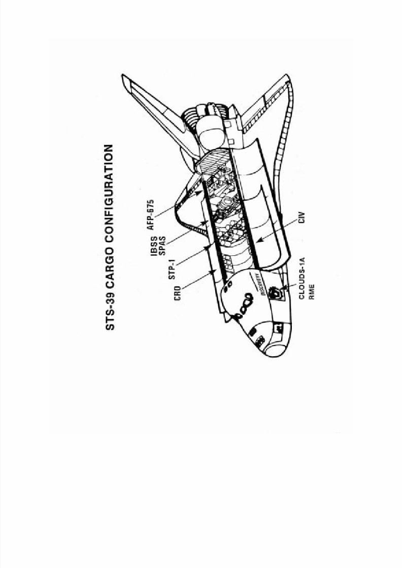
Carried aboard Discovery on its 12th flight, the 39th Shuttle mission, will be Air Force Program-675
(AFP-675); the Infrared Background Signature Survey (IBSS) mounted on the Shuttle Pallet Satellite-II
(SPAS-II); the Critical Ionization Velocity (CIV) experiment; three Chemical Release Observation (CRO)
subsatellites; the Space Test Payload (STP-1) and a classified payload in a Multi-Purpose Experiment
Canister (MPEC).
Inside Discovery's crew cabin will be the Cloud Logic to Optimize the Use of Defense Systems-1A
(CLOUDS-1A) experiment and the Radiation Monitoring Equipment-III (RME-III).
Work with these payloads during the flight will involve extensive maneuvering, rendezvous and close
proximity operations by Discovery. STS-39 is currently working toward a 3:49 a.m. EST launch on March
9, 1991. Landing is set for Edwards Air Force Base, CA, at 11:14 a.m. EST on March 17, giving the flighta planned length of 8 days, 7 hours and 26 minutes.
AFP-675 is a collection of scientific instruments to observe targets such as the atmosphere, the aurora and
stars in infrared, far ultraviolet, ultraviolet and X-ray wavelengths. AFP-675 instruments also will analyze
the spectrum of various targets and gases released from or around the Shuttle. AFP-675 is sponsored by the
U.S. Air Force's Space Systems Division and may provide a better understanding of the difficulties in
identifying spacecraft with remote sensors and distinguishing those spacecraft from naturally occurring
phenomena. The AFP-675 instruments also are to study several astronomical targets of interest.
The Strategic Defense Initiative Organization's IBSS experiment, mounted on the SPAS-II platform, will
be deployed and retrieved by Discovery so that SPAS-II can observe the Shuttle's engine firings from afar.
IBSS will observe and record the infrared signature of these firings and also will perform infrared
observations of other targets, including three CRO subsatellites to be released from Discovery. IBSS willobserve common rocket fuels nitrogen tetroxide, monomethyl hydrazine and dimethyl hydrazine released
from the three CRO subsatellites after they are deployed by Discovery.
IBSS also will observe releases of the gases xenon, neon, carbon dioxide and nitric oxide from canisters in
Discovery's payload bay. These gases are part of the CIV experiment, which, with instruments in the
payload bay, will observe the releases simultaneously with IBSS. IBSS is sponsored by SDIO and
information from its studies may assist in developing remote sensors that can identify missiles.
The STP-1 experiment is a varied collection of scientific instruments, including one that will observe the
luminous "airglow" effect of atomic oxygen on Discovery; one that will test a new method of flowing
rocket propellants in weightlessness to assist in the design of future engines; and another to observe the
fringes of Earth's atmosphere at various times, including sunrise and sunset, in ultraviolet wavelengths.
STP-1 is sponsored by the Air Force's Space Systems Division.
Inside the crew cabin, the CLOUDS-1A experiment is a camera the crew will use to photograph various
cloud formations on the Earth to better understand cloud movements and structures. The RME-III
experiment is designed to monitor radiation levels inside the cabin during the flight.

8/8/2019 STS-39 Press Kit
http://slidepdf.com/reader/full/sts-39-press-kit 7/48
Commanding Discovery will be Navy Capt. Michael L. Coats. Air Force Major L. Blaine Hammond will
serve as pilot. Mission specialists include Gregory J. Harbaugh; USAF Lt. Col. Don McMonagle; USAF
Col. Guion Bluford; C. Lacy Veach; and Richard J. Hieb.
The flight crew will operate in two teams to accommodate 24-hour a day observations aboard Discovery, with each
team working a 12-hour shift. On the Red Team will be Hammond, Veach and Hieb. On the Blue Team will be
Harbaugh, McMonagle and Bluford. Coats will keep his own hours, independent of any assigned shift.
(END OF GENERAL RELEASE; BACKGROUND INFORMATION FOLLOWS.)
8/8/2019 STS-39 Press Kit
http://slidepdf.com/reader/full/sts-39-press-kit 8/48
STS-39 QUICK LOOK
Launch Date: Mar. 9, 1991
Landing Site: Kennedy Space Center, FL, Pad 39-A
Launch Window: 3:49 a.m. - 6:51 a.m. EST
Orbiter: Discovery (OV-103)
Orbit: 140 x 140 nautical miles
Inclination: 57 degrees
Landing Date/Time: Mar. 17, 1991, 11:14 a.m. EST
Primary Landing Site: Edwards Air Force Base, CA
Abort Landing Sites: Return to Launch Site - Kennedy Space Center, FL
Transoceanic Abort Landing - Zaragoza and Moron, Spain
Abort Once Around - Northrup Strip, White Sands, NM
Crew: Michael L. Coats, Commander
Blaine Hammond Jr., Pilot
Gregory L. Harbaugh, Mission Specialist 1
Donald R. McMonagle, Mission Specialist 2
Guion S. Bluford, Mission Specialist 3
C. Lacy Veach, Mission Specialist 4
Richard J. Hieb, Mission Specialist 5
Cargo Bay Payloads: IBSS/SPAS-II
CIV
CRO
STP-1MPEC
Middeck Payloads: Cloud Logic to Optimize the Use of Defense Systems (CLOUDS-1A)
Radiation Monitoring Experiment (RME-III)
8/8/2019 STS-39 Press Kit
http://slidepdf.com/reader/full/sts-39-press-kit 9/48
SUMMARY OF MAJOR ACTIVITIES
Flight Day One
Ascent
OMS 2
IBSS on-orbit checkout
AFP-675 activation
RME-III activationDSO
Flight Day Two
AFP-675 operations
SPAS pre-deploy checkout
IBSS/SPAS-II unberth; deploy
IBSS/SPAS-II far-field observations
Flight Day Three
IBSS/SPAS-II far-field observations
IBSS/SPAS-II near-field observations
CRO-C deploy
Flight Day Four
IBSS/SPAS-II near-field observations
IBSS/SPAS-II rendezvous
CRO-B deploy
IBSS/SPAS-II retrieval; berthing
DSO
Flight Day Five
AFP-675 operations
CRO-A deploy
Flight Day Six
SPAS-II pre-deploy checkoutIBSS/SPAS-II unberthing; RMS operations
Flight Day Seven
IBSS/SPAS-II berthing
AFP-675 operations
Flight Day Eight
AFP-675 operations
STP-I operations
Flight Control Systems checkout
MPEC deploy
Payload deactivation
Cabin stow
Flight Day Nine
RME-III deactivation; stow
Deorbit; landing
8/8/2019 STS-39 Press Kit
http://slidepdf.com/reader/full/sts-39-press-kit 10/48
SPACE SHUTTLE ABORT MODES
Space Shuttle launch abort philosophy aims toward safe and intact recovery of the flight crew, orbiter and its
payload. Abort modes include:
• Abort-To-Orbit (ATO) -- Partial loss of main engine thrust late enough to permit reaching a minimal 105-
nautical mile orbit with orbital maneuvering system engines.
• Abort-Once-Around (AOA) -- Earlier main engine shutdown with the capability to allow one orbit around
before landing at either Edwards Air Force Base, CA; White Sands Space Harbor (Northrup Strip), NM; or the
Shuttle Landing Facility (SLF) at Kennedy Space Center, FL.
• Trans-Atlantic Abort Landing (TAL) -- Loss of two main engines midway through powered flight would force
a landing at either Zaragoza or Moron, Spain.
• Return-To-Launch-Site (RTLS) -- Early shutdown of one or more engines, and without enough energy to reach
Zaragoza, would result in a pitch around and thrust back toward KSC until within gliding distance of the SLF.
STS-39 contingency landing sites are Edwards AFB, White Sands, Kennedy Space Center, Zaragoza and Moron.
8/8/2019 STS-39 Press Kit
http://slidepdf.com/reader/full/sts-39-press-kit 11/48
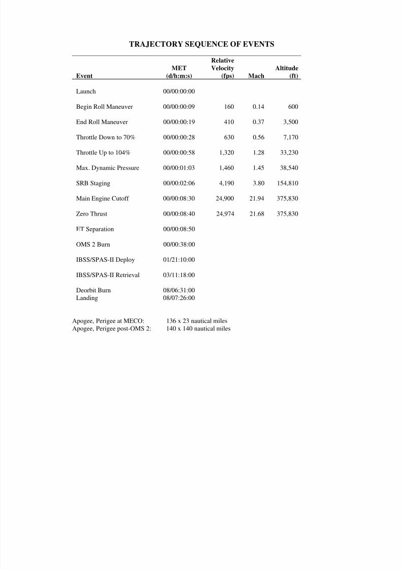
TRAJECTORY SEQUENCE OF EVENTS
Event
MET
(d/h:m:s)
Relative
Velocity
(fps) Mach
Altitude
(ft)
Launch 00/00:00:00
Begin Roll Maneuver 00/00:00:09 160 0.14 600
End Roll Maneuver 00/00:00:19 410 0.37 3,500
Throttle Down to 70% 00/00:00:28 630 0.56 7,170
Throttle Up to 104% 00/00:00:58 1,320 1.28 33,230
Max. Dynamic Pressure 00/00:01:03 1,460 1.45 38,540
SRB Staging 00/00:02:06 4,190 3.80 154,810
Main Engine Cutoff 00/00:08:30 24,900 21.94 375,830
Zero Thrust 00/00:08:40 24,974 21.68 375,830
ET Separation 00/00:08:50
OMS 2 Burn 00/00:38:00
IBSS/SPAS-II Deploy 01/21:10:00
IBSS/SPAS-II Retrieval 03/11:18:00
Deorbit Burn 08/06:31:00
Landing 08/07:26:00
Apogee, Perigee at MECO: 136 x 23 nautical miles
Apogee, Perigee post-OMS 2: 140 x 140 nautical miles
8/8/2019 STS-39 Press Kit
http://slidepdf.com/reader/full/sts-39-press-kit 12/48
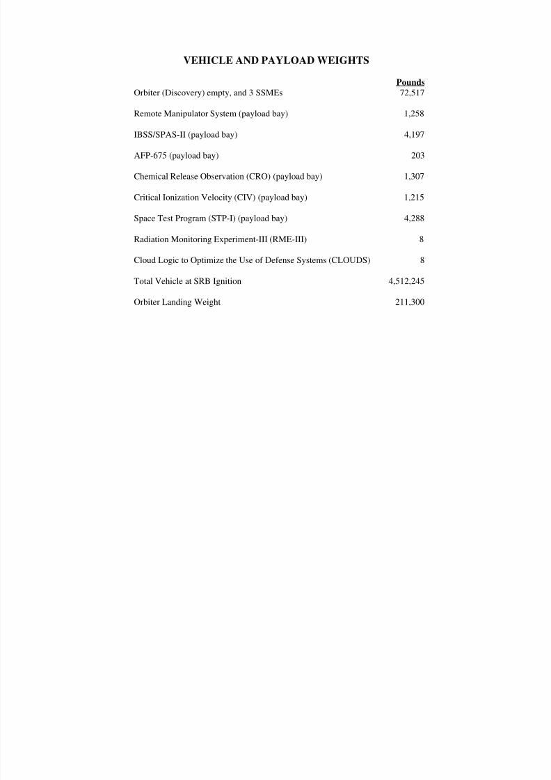
VEHICLE AND PAYLOAD WEIGHTS
Pounds
Orbiter (Discovery) empty, and 3 SSMEs 72,517
Remote Manipulator System (payload bay) 1,258
IBSS/SPAS-II (payload bay) 4,197
AFP-675 (payload bay) 203
Chemical Release Observation (CRO) (payload bay) 1,307
Critical Ionization Velocity (CIV) (payload bay) 1,215
Space Test Program (STP-I) (payload bay) 4,288
Radiation Monitoring Experiment-III (RME-III) 8
Cloud Logic to Optimize the Use of Defense Systems (CLOUDS) 8
Total Vehicle at SRB Ignition 4,512,245
Orbiter Landing Weight 211,300
8/8/2019 STS-39 Press Kit
http://slidepdf.com/reader/full/sts-39-press-kit 13/48
STS-39 PRELAUNCH PROCESSING
Kennedy Space Center workers began preparing Discovery for its 12th flight into space when the vehicle was towed
into the Orbiter Processing Facility on Oct. 18 following its previous mission, STS-33.
Discovery spent about 15 weeks in the processing facility undergoing about 22 modifications and routine testing.
One of the significant changes made was the installation of the five new general purpose computers.
Space Shuttle main engine locations for this flight are as follows: engine 2026 in the No. 1 position, engine 2030 in
the No. 2 position, and engine 2029 in the No. 3 position.
Booster stacking operations on mobile launcher platform 2 began Nov. 7 and were completed Dec. 13. The external
tank was mated to the boosters Dec. 18 and the Orbiter Discovery was bolted to the tank on Jan. 30.
STS-39 primary payloads were installed in Discovery's payload bay in the OPF and at the launch pad. Payloads
installed in the OPF include the Critical Ionization Velocity payload and the Chemical Release Observatory. The
U.S. Air Force payload 675 and the Shuttle Pallet Satellite-II were installed at the launch pad Feb. 5. The vehicle
was rolled out to Launch Pad 39-A on Feb. 4. A dress rehearsal launch countdown was held Feb. 7-8 at KSC.
The launch countdown will begin about 3 days prior to the launch. During the countdown, the orbiter's onboard fuel
and oxidizer storage tanks will be loaded and all orbiter systems will be prepared for flight. About 9 hours beforelaunch, the external tank will be filled with its flight load of a half a million gallons of liquid oxygen and liquid
hydrogen propellants. About 2 1/2 hours before liftoff, the flight crew will begin taking their assigned seats in the
crew cabin.
KSC's recovery teams will prepare the orbiter Discovery for the return trip to Florida following the end-of-mission
landing at Edwards AFB, CA. Orbiter turnaround operations at Dryden Flight Research Facility typically take about
5 days.
8/8/2019 STS-39 Press Kit
http://slidepdf.com/reader/full/sts-39-press-kit 14/48
SHUTTLE ADVANCED GENERAL PURPOSE COMPUTER
On STS-39, Discovery's avionics system will feature the first set of five upgraded general purpose computers
(GPCs), plus a spare, to fly aboard the Shuttle.
The updated computers have more than twice the memory and three times the processing speed of their
predecessors. Officially designated the IBM AP-101S, built by IBM, Inc., they are half the size, about half the
weight and require less electricity than the first-generation GPCs. The central processor unit and input/outputprocessor, previously installed as two separate boxes, are now a single unit.
The new GPCs use the existing Shuttle software with only subtle changes. However, the increases in memory and
processing speed allow for future innovations in the Shuttle's data processing system.
Although there is no real difference in the way the crew will operate with the new computers, the upgrade increases
the reliability and efficiency in commanding the Shuttle systems. The predicted "mean time between failures"
(MTBF) for the advanced GPCs is 6,000 hours. The MTBF for the original GPCs is 5,200 hours.
Specifications
Dimensions: 19.55" x 7.62" x 10.2"Weight: 64 lbs.
Memory capacity: 262,000 words (32-bits each)
Processing rate: 1 million instructions per second
Power requirements: 550 watts
8/8/2019 STS-39 Press Kit
http://slidepdf.com/reader/full/sts-39-press-kit 15/48
STS-39 MISSION OVERVIEW
The STS-39 mission is comprised of two primary payloads: Air Force Program 675 (AFP-675) and the Strategic
Defense Initiative's (SDIO) Infrared Background Signature Survey (IBSS).
There also are two secondary payloads; Space Test Payload (STP-1) and a Multi-Purpose Experiment Canister
(MPEC). Two mid-deck experiments, CLOUDS-1A and RME III, are included on the STS-39 mission. IBSS and
AFP-675 have scheduled observing time throughout the mission with a small amount of dedicated time for both
STP-1 and MPEC on the last day of the mission.
The AFP-675 payload is sponsored by SDIO and Air Force Systems Command's Space Systems Division (SSD). It
contains three experiments sponsored by the Phillips Laboratory's Geophysics Directorate, by the Naval Research
Laboratory, and by the Los Alamos National Laboratory, respectively. The prime integration contractor for the
payload is Lockheed Missiles and Space Company, Inc. AFP-675 is a unique demonstration of the ability to
command, control and evaluate a system of experiments without ground commands or telemetry data.
Voice (although not necessary) will be included on this mission for communication between the crew and the
ground to discuss the experiments.
The AFP-675 payload will remain in the payload bay during the mission, and commanding of the experiments will
be accomplished by the crew from a panel in the aft flight deck. The experiments will be measuring infrared,
ultraviolet, visible and X-ray emissions. One of the important observations for the mission is the aurora. The launchdate and time were chosen to assure visibility of the aurora.
SDIO's IBSS payload is composed of three separate systems, the Shuttle Pallet Satellite (SPAS-II), the Critical
Ionization Velocity (CIV) system and the Chemical Release Observation (CRO) experiment. SDIO has program
management responsibility. The SPAS-II was developed by Messerschmitt-Bolkow-Blohm (MBB).
The CIV portion is managed by the Geophysics Directorate, and the CRO portion is managed by the Western Space
Technology Center. Mission operations are managed by SSD.
The SPAS-II structure supports a cryogenically cooled infrared sensor, an ultraviolet multispectral sensor and low
light level television cameras. The SPAS-II will be deployed and maneuvered to observe various targets and can be
commanded by the on-board crew or by the ground.
The CRO is composed of three separate subsatellite structures that will be deployed and will release chemicals uponground command to be observed by the SPAS infrared sensors. Each subsatellite is loaded with a different
chemical.
The CIV structure is composed of four separate gas canisters which remain attached to the orbiter and will release
gas upon command to be observed by the SPAS sensors. Each cylinder is loaded with a different gas; xenon, neon,
carbon dioxide and nitrous oxide.
SSD sponsors the STP-1 payload which is a standard Goddard Space Flight Center (GSFC) Hitchhiker structure
supporting five experiments. Experiments are sponsored by the Naval Research Laboratory, the Rocket Propulsion
Directorate of the Phillips Laboratory, the Geophysics Directorate, GSFC, and SSD.
STP-1 remains in the cargo bay and is commanded from a control center at Goddard Space Flight Center. The
UVLIM experiment will collect airglow measurements, ALFE will evaluate advanced propellant management
systems, and SKIRT will collect infrared, visible and ultraviolet data on Shuttle glow. DSE will test advanced datamanagement concepts, and APM will collect particles to study particulate contamination in the Shuttle bay.
MPEC is a multipurpose experiment canister sponsored by SSD. The MPEC will deploy a classified experiment on
the last day of the mission.
There are two mid-deck experiments on the STS-39 mission. The CLOUDS-1A experiment will study cloud cover,
and the RME-III experiment will measure ionizing radiation exposure in the orbiter cabin.
8/8/2019 STS-39 Press Kit
http://slidepdf.com/reader/full/sts-39-press-kit 16/48
8/8/2019 STS-39 Press Kit
http://slidepdf.com/reader/full/sts-39-press-kit 17/48
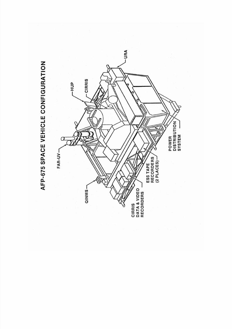
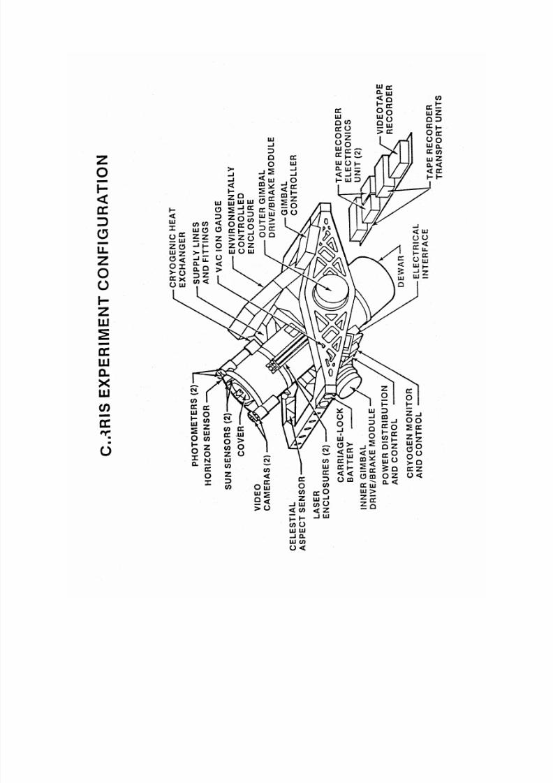
AIR FORCE PAYLOAD-675
Cryogenic Infrared Radiance Instrumentation For Shuttle (CIRRIS-1A)
The CIRRIS instrument is sponsored by the Strategic Defense Initiative Organization (SDIO), and program
responsibility is under the Phillips Laboratory's Geophysics Directorate at Hanscom Air Force Base, MD. The
sensor prime contractor is Utah State University with major subcontractors Space Data Corporation, Sensor System
Group and Boston College.
CIRRIS-1A is the highest priority experiment being flown on the AFP-675 space vehicle. The experiment is
designed to be operated by Discovery's crew from a command panel in the aft flight deck.
The experiment operates in the infrared portion of the electromagnetic spectrum (wavelength between 2.5 to 25
micro-meters). The experiment will obtain simultaneous spectral and spatial measurements of airglow and auroral
emissions.
The data obtained from the mission should help answer questions regarding the optimum atmospheric windows for
detecting cold body targets, the background radiance levels in various regions, the spatial structure (clutter) of the
background, and the variability of Earth limb emissions during day/night airglow and auroral events. This
information will help DOD design surveillance systems.
There is a low light level television co-aligned on the sensor telescope which can be used by the crew to acquire and
track the auroral displays and celestial calibration targets.
One primary mission objective is to measure the spectral and spatial characteristics of auroral emissions. The pre-
midnight/midnight sector of the Northern and Southern auroral oval is expected to exhibit the most intense infrared
emissions and therefore, is of particular interest. An auroral watch will be maintained by a network of ground
personnel to monitor the level of auroral activity. In the event of an intense auroral display, this team would alert
Discovery's crew of the location and intensity of the aurora.
Earth limb emissions will be collected covering a range of altitudes, latitudes, day/night and geomagnetic
conditions.
To provide a radiometric calibration of the infrared sensors, certain known celestial sources will be measured duringthe mission.
Discovery will be maneuvered to provide the proper attitude for observations and to provide the required scanning
and pointing capability. The sensor is mounted on a two-axis gimbal.
Gravity gradient is the primary attitude for CIRRIS-1A data collection. It is the only attitude maintainable by the
orbiter without the use of the reaction control system which produces unacceptable contaminates.
8/8/2019 STS-39 Press Kit
http://slidepdf.com/reader/full/sts-39-press-kit 18/48
8/8/2019 STS-39 Press Kit
http://slidepdf.com/reader/full/sts-39-press-kit 19/48
8/8/2019 STS-39 Press Kit
http://slidepdf.com/reader/full/sts-39-press-kit 20/48
Aurora Details
Aurora are created by solar activity. When a solar flare, sun spot or coronal hole occurs within a particular area of
the sun's disk, an increased number of energetic particles is directed towards the Earth. As the solar wind accelerates
with the Earth's magnetosphere, a generator effect is produced which accelerates electrons down the Earth's
magnetic field lines. As these electrons impinge upon the Earth's atmosphere, oxygen and nitrogen are excited and
ionized to produce aurorae. The aurorae emit visible, ultraviolet, infrared and radio frequencies. Because the
electrons precipitate down the geomagnetic field lines, aurorae are produced in an oval shaped zone roughlycentered around the magnetic pole regions of the North and South poles.
The shape and size of the oval is dependent on the intensity of the solar wind. The intensity of the aurora within the
oval is variable. The objective of the mission is to observe an extremely active aurora. The two primary indicators
for predicting when an active aurora might appear are solar activity and geomagnetic disturbance. These events will
both be monitored during the mission.
A ground station magnetometer network and Defense Meteorological Satellite Program (DMSP) satellite coverage
will be utilized to detect whether an active aurora is in progress. This network is located in the Northern
Hemisphere and will collect simultaneous scientific measurements as well as provide a near real-time detection
capability. The southern aurora is a mirror image of the northern aurora. If there is an active northern aurora then
the southern aurora also will be active.
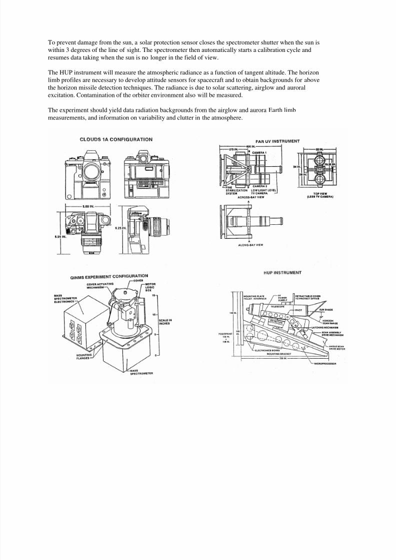
FAR Ultraviolet Cameras (FAR UV)
The FAR Ultraviolet Cameras experiment is sponsored by the Naval Research Laboratory. The hardware is a part of
the AFP-675 payload. The instrumentation consists of two electrographic Schmidt cameras. A course-pointing two
axis gimbal platform and a low light level TV camera for finding the objects and guiding the instrument. The
instrument also has a stabilization system for long exposures on celestial objects. The instrument weighs
approximately 550 pounds and the dimensions are approximately 60" x 32" x 20".
The cameras will record naturally-occurring and man-made emission phenomena in near-Earth space in the 1050-
1600 angstroms (A) and 1230-2000A wavelength ranges. The phenomena of interest include day and night airglow,
diffuse aurorae and the orbiter environment. Of particular interest is the orbiter thruster and surface glow effects.
The experiment also will make observations of interplanetary and interstellar media, stars, extragalactic objects,
effects of chemical deposition and atmospheric density measurements by stellar occultation.
Each camera has a film transport loaded with 150 feet of film yielding up to 900 frames of data. The gimbaled
platform allows pointing of FAR UV to be somewhat independent of orbiter attitude. The outer gimbal can travel
between +/- 80 degrees and the inner gimbal can travel between +/- 22 degrees.
The experiment is commanded by a crew member who views the TV monitor to determine where the camera is
pointing as he moves the camera into position.
The sun sensor is an array of silicon solar cells which outputs a voltage of 5 volts in full sunlight. As the output
from the sun sensor in excess of 3 volts indicates the sun is shining into the payload bay and hence, the FAR UV
high voltage must be turned off and the doors closed.
The terrestrial atmospheric observations include northern and southern diffuse aurora, snapshot views of discrete
aurora, night airglow with attention to the tropical arcs and twilight airglow. Stellar occultation observations will
occur concurrent with airglow observations. Any unique phenomena such as meteor showers should be noted if they
occur in airglow or aurora viewing periods.
8/8/2019 STS-39 Press Kit
http://slidepdf.com/reader/full/sts-39-press-kit 21/48
The celestial target observations include the diffuse nebulae, diffuse galactic background, star fields at high and low
galactic latitudes, and also nearby external galaxies.
The primary Shuttle environment events are the primary RCS and OMS thruster firings (in daylight and dark) and
Shuttle glow. Secondary interests are Shuttle contamination effects such as fuel cell purges, flash evaporator events
and water dumps.
Uniformly Redundant Array (URA)
The URA experiment is sponsored by the Department of Energy and Los Alamos National Laboratory.
The URA is designed to conduct studies of astrophysical sources of X-ray radiation. The instrument, a part of the
AFP-675 payload, is an assembly consisting of a detector, a 35 mm camera and an electronics package. The
aperture plate of the detector contains over 26,000 hexagonal holes to collect the X-ray photons. Objects will be
selected to test the capability of the URA to image point sources, complex collections of point sources and extended
objects. The instrument will be operated both in a staring and slow scan mode. The URA experiment will be
controlled by a mission specialist via the CMP (Command and Monitor Panel).
The URA must not only detect X-rays of interest but must also suppress detection of particles that are present as
background. The backgrounds of concern are mainly cosmic rays (relativistic protons and alpha particles) and
charged particles (electrons above a 50 keV energy) trapped by the Earth's magnetic field. Because such particles
penetrate the detector walls or window, the backgrounds are rejected by anti-coincidence, second moment and rise
time discrimination techniques.
The extended charge distribution from an energetic charged particle, as opposed to an X-ray photon, produces a
slower amplifier pulse because it is collected over a finite period of time. Rise time discrimination is thus an
independent means of background rejection.
Despite the background rejection provisions, URA will not operate usefully at high levels of background. Cosmic
ray background is less at low latitude and altitude because of the shielding effect of the Earth's magnetic field. X-ray
experiments are not successful in high background regions, which are found at high altitude, and high magnetic
latitude, and in the South Atlantic Anomaly.
Low altitude, low latitude will increase the success of the URA observations.
Horizon Ultraviolet Program (HUP)
The HUP is an AF Geophysics Laboratory experiment to demonstrate a capability to measure the spatial and
spectral characteristics of the Earth's horizon as observed in the ultraviolet wavelength region and to analyze Shuttle
contamination.
The instrument weighs less than 40 pounds and is approximately 15" x 21" x 9".
The ultraviolet instrument is smaller and does not require cooling like the infrared instruments. The experiment runs
continuously during the mission. The line of sight of the instrument is in the -Z direction, vertically out of the
Shuttle bay.
The telescope assembly is pivoted about an axis which enables the field of view to vary from local horizontal to a
few degrees below the hard Earth horizon. Data will be collected using continuous angle scans at a series of
wavelengths in the range of 1100-1900 A, continuous wavelength scans in a fixed direction and a fixed wavelength
fixed direction.
8/8/2019 STS-39 Press Kit
http://slidepdf.com/reader/full/sts-39-press-kit 22/48
To prevent damage from the sun, a solar protection sensor closes the spectrometer shutter when the sun is
within 3 degrees of the line of sight. The spectrometer then automatically starts a calibration cycle and
resumes data taking when the sun is no longer in the field of view.
The HUP instrument will measure the atmospheric radiance as a function of tangent altitude. The horizon
limb profiles are necessary to develop attitude sensors for spacecraft and to obtain backgrounds for above
the horizon missile detection techniques. The radiance is due to solar scattering, airglow and auroral
excitation. Contamination of the orbiter environment also will be measured.
The experiment should yield data radiation backgrounds from the airglow and aurora Earth limb
measurements, and information on variability and clutter in the atmosphere.

8/8/2019 STS-39 Press Kit
http://slidepdf.com/reader/full/sts-39-press-kit 23/48
Quadrupole Ion-Neutral Mass Spectrometer (QINMS)
The QINMS experiment is sponsored by the Phillips Laboratory's Geophysics Directorate. The mass spectrometer
instrument weighs approximately 28 pounds.
The hardware, part of the AFP-675 payload, is mounted to the ESS and does not gimbal.
The primary role of QINMS is to support CIRRIS by measuring the amount and nature of orbiter baycontamination, particularly water concentration. CIRRIS will not be operated until contamination levels are low.
QINMS will collect data continuously throughout the flight with operations controlled by a Mission Specialist via
the CMP.
Data also will be collected while passing through the auroral zone and polar latitude. Levels of hydrogen, oxygen,
water vapor and other gases will be measured.
8/8/2019 STS-39 Press Kit
http://slidepdf.com/reader/full/sts-39-press-kit 24/48
INFRARED BACKGROUND SIGNATURE SURVEY (IBSS)
IBSS Overview
Infrared Background Signature Survey is a Strategic Defense Initiative Organization sponsored program for the
purpose of obtaining scientific data for use in the development of ballistic missile defense sensor systems.
IBSS is composed of three separate elements: the Shuttle Pallet Satellite II (SPAS -II), the Critical IonizationVelocity (CIV) package, and the Chemical Release Observation (CRO) experiment. In addition to sponsoring the
program, SDIO also manages the overall program. Supporting SDIO in program management are several systems
engineering and technical analysis firms, including: Stears, Kiya and Wright of Arlington, Va.; Orbital Systems
Limited of Lanham, Md.; Nichols Research Corp. of Vienna, VA., and Hernandez Engineering Inc. of Houston,
TX. The SPAS-II hardware is developed and manufactured by Messerschmitt-Bolkow-Blohm GmbH of Munich,
Germany. Mounted on the SPAS-II are two sensor systems: an infrared spectrometer/radiometer built by Kayser-
Threde of Germany housed in cryostat (cryogenically cooled instrument chamber) built by Linde of Germany and a
multispectral Arizona Imager/Spectrograph (AIS) built by the University of Arizona at Tucson, AZ.
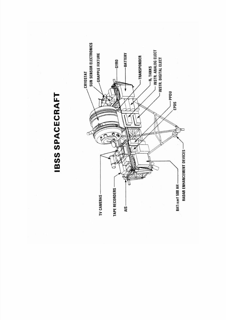
Shuttle Pallet Satellite II (SPAS-II)
The SPAS-II element incorporates a liquid helium cooled infrared sensor, the Arizona Imager/Spectrograph (AIS)multispectral sensor, two low light level television cameras and various support subsystems on a modular graphite-
epoxy structure. SPAS-II will be deployed from the orbiter using the Remote Manipulator System (RMS) and will
maneuver at ranges of up to 20 km from the orbiter to gather spectral and spatial data during several experiments.
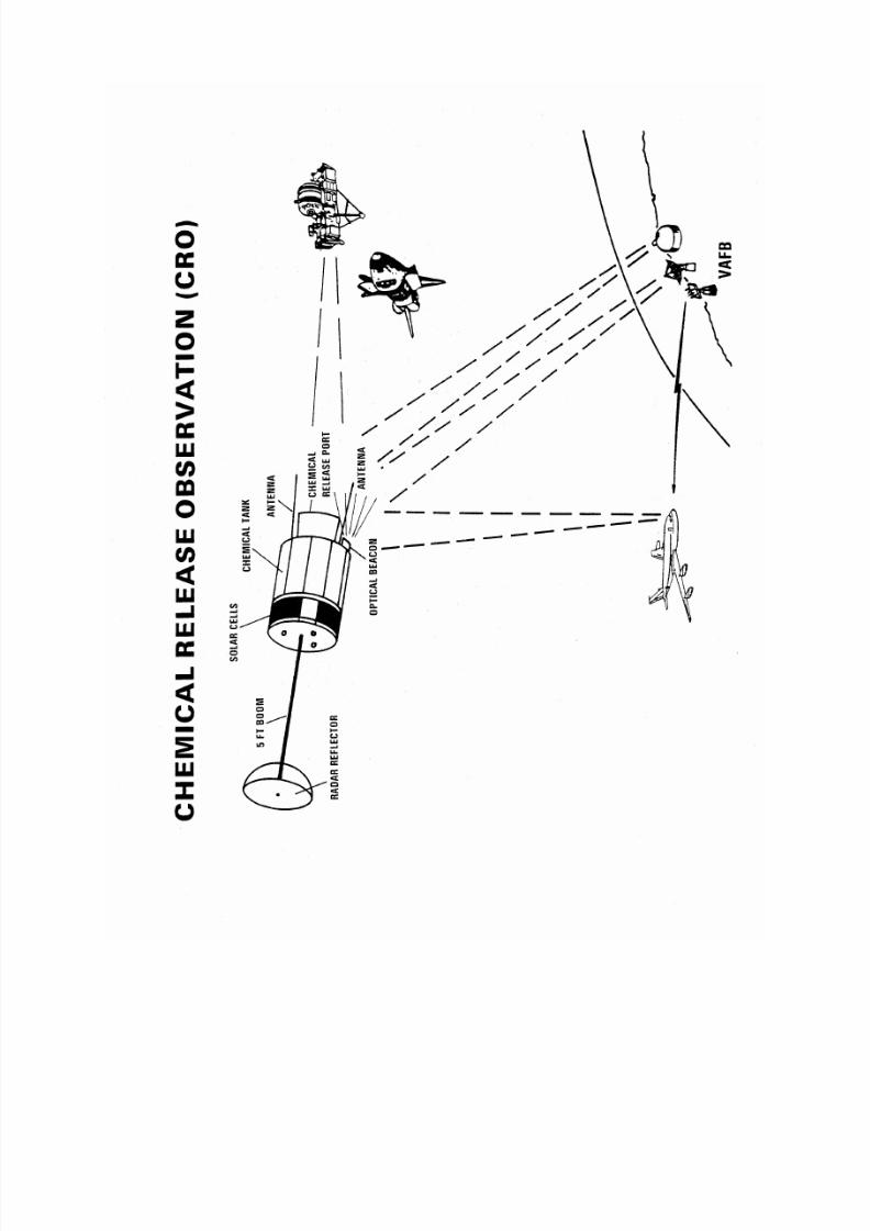
Chemical Release Observation (CRO)
The Chemical Release Observation (CRO) portion of the Infrared Background Signature Survey (IBSS) mission is
an experiment designed to collect infrared, visible and ultraviolet time-resolved radiometric data associated with the
release of liquid rocket propellants in near Earth orbit. The experiment is composed of three separate subsatellites
containing chemicals and their launchers.
Since the three chemical releases will produce short-lived clouds of vapor and frozen particles in orbit near theShuttle, it is possible that a faint glow of visible light may occur due to the interaction of the vapor cloud with
oxygen atoms in the upper atmosphere. It is not expected, however, that the vapor glow from any of the releases
will be bright enough to be detected by the unaided eye on the ground. The chances of observers near Vandenberg
seeing the first and only nighttime scheduled release experiment are very remote.
The cloud of frozen particles, however, can scatter sunlight producing visible light with much greater intensity. The
sunlight scattered from the particle cloud will not be as intense as the daytime sky, however, so it is unlikely that
either the second or third release can be viewed from the ground for the scheduled launch and mission time line. If
the launch is delayed a couple of hours, however, the first scheduled release could occur under pre-dawn twilight
conditions on the west coast. This situation would provide optimal viewing conditions as the release would occur in
sunlight while a west coast observer would be in darkness. Under these conditions, the release would initially
appear as a disk of white light approximately the size of the full moon (though somewhat dimmer). The cloud will
continue to grow and gradually dim after the flow of liquid ends. The remnants of the bright cloud will only persistfor a few minutes.
8/8/2019 STS-39 Press Kit
http://slidepdf.com/reader/full/sts-39-press-kit 25/48
8/8/2019 STS-39 Press Kit
http://slidepdf.com/reader/full/sts-39-press-kit 26/48
8/8/2019 STS-39 Press Kit
http://slidepdf.com/reader/full/sts-39-press-kit 27/48
CRO Management
The CRO element is managed by the Air Force Space Technology Center from their West Coast (Los Angeles)
office. The CRO subsatellites and launcher mechanisms are designed and manufactured by Defense Systems Inc.,.
of McLean, Va., while the launcher cylinders and support beams are provided by NASA/Goddard Space Flight
Center at Greenbelt, MD. Subsatellite ground control and telemetry is provided by USAF 6595th Test & Evaluation
Group and the Western Test Range at Vandenberg AFB, CA, supported by Federal Electric Corp. Aircraft sensor
platform operations for collecting CRO data in the VAFB area are provided by the HALO aircraft, operated by
Phillips Laboratory's Weapons Directorate and 4950th Test Group at Kirtland AFB, N.M., supported by BDM Corp.
of Albuquerque, N.M.
IBSS mission integration, launch site operations and payload flight operations are managed by the Space Systems
Division, Air Force Systems Command, supported by The Aerospace Corporation and Rockwell International Space
Division.
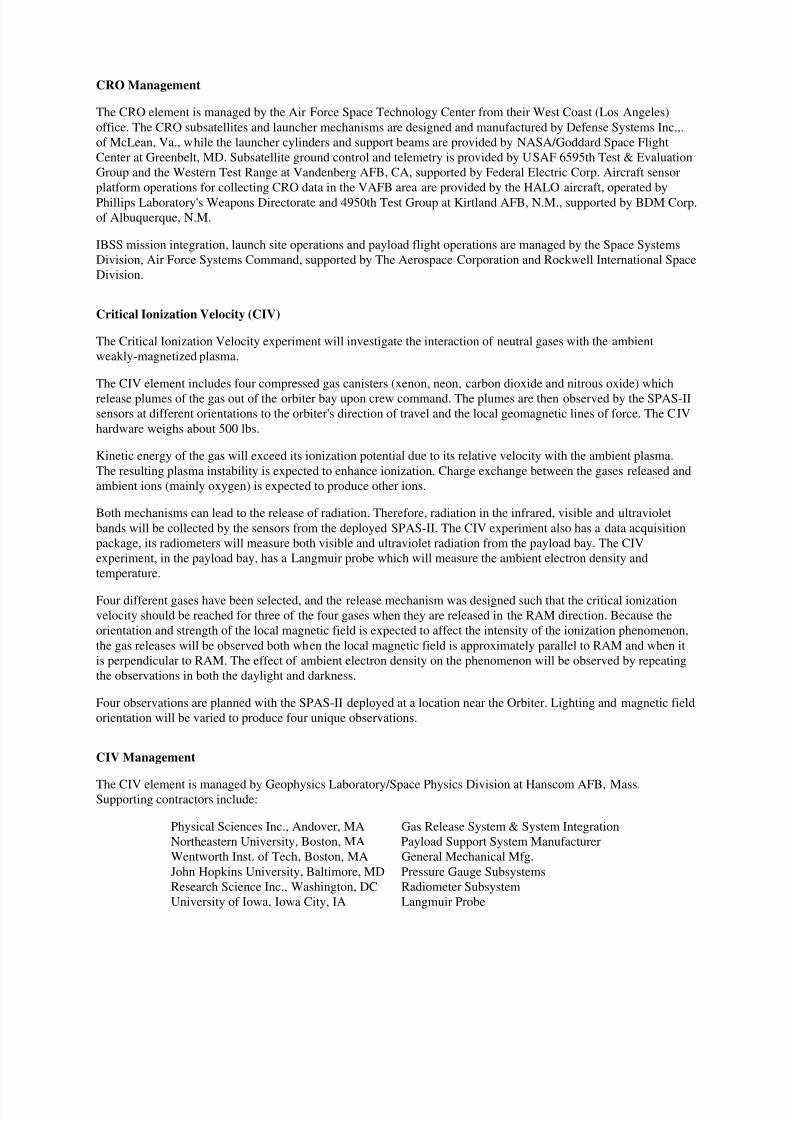
Critical Ionization Velocity (CIV)
The Critical Ionization Velocity experiment will investigate the interaction of neutral gases with the ambient
weakly-magnetized plasma.
The CIV element includes four compressed gas canisters (xenon, neon, carbon dioxide and nitrous oxide) which
release plumes of the gas out of the orbiter bay upon crew command. The plumes are then observed by the SPAS-II
sensors at different orientations to the orbiter's direction of travel and the local geomagnetic lines of force. The CIV
hardware weighs about 500 lbs.
Kinetic energy of the gas will exceed its ionization potential due to its relative velocity with the ambient plasma.
The resulting plasma instability is expected to enhance ionization. Charge exchange between the gases released and
ambient ions (mainly oxygen) is expected to produce other ions.
Both mechanisms can lead to the release of radiation. Therefore, radiation in the infrared, visible and ultraviolet
bands will be collected by the sensors from the deployed SPAS-II. The CIV experiment also has a data acquisition
package, its radiometers will measure both visible and ultraviolet radiation from the payload bay. The CIV
experiment, in the payload bay, has a Langmuir probe which will measure the ambient electron density and
temperature.
Four different gases have been selected, and the release mechanism was designed such that the critical ionization
velocity should be reached for three of the four gases when they are released in the RAM direction. Because the
orientation and strength of the local magnetic field is expected to affect the intensity of the ionization phenomenon,
the gas releases will be observed both when the local magnetic field is approximately parallel to RAM and when it
is perpendicular to RAM. The effect of ambient electron density on the phenomenon will be observed by repeating
the observations in both the daylight and darkness.
Four observations are planned with the SPAS-II deployed at a location near the Orbiter. Lighting and magnetic field
orientation will be varied to produce four unique observations.
CIV Management
The CIV element is managed by Geophysics Laboratory/Space Physics Division at Hanscom AFB, Mass.Supporting contractors include:
Physical Sciences Inc., Andover, MA Gas Release System & System Integration
Northeastern University, Boston, MA Payload Support System Manufacturer
Wentworth Inst. of Tech, Boston, MA General Mechanical Mfg.
John Hopkins University, Baltimore, MD Pressure Gauge Subsystems
Research Science Inc., Washington, DC Radiometer Subsystem
University of Iowa, Iowa City, IA Langmuir Probe
8/8/2019 STS-39 Press Kit
http://slidepdf.com/reader/full/sts-39-press-kit 28/48
8/8/2019 STS-39 Press Kit
http://slidepdf.com/reader/full/sts-39-press-kit 29/48
IBSS OBJECTIVES
The Infrared Background Signature Survey is a Strategic Defense Initiative Organization sponsored program for the
purpose of obtaining scientific data for use in the development of ballistic missile defense sensor systems. The IBSS
mission will involve the collection of infrared, ultraviolet and visible measurements of natural and induced
geophysical phenomena.
Using the SPAS-II sensors at various ranges from the orbiter, spectral, spatial and temporal radiometricobservations will be made of the exhaust plumes when the orbiter's orbital maneuvering systems (OMS) fires and
creates replications of ICBM booster and midcourse engine firings. Interaction of the outer plume regions with the
atmosphere will be characterized, as well as the region near the exit nozzle. The single engine OMS firings for these
observations represent the first time such firings have been attempted in space by the orbiter.
The Chemical Release Observations (CRO) will be carried out by deploying each of the three CRO subsatellites
from the cargo bay at about 3.5 feet per second, allowing them to separate until the subsatellite trails the SPAS-II by
50 to 200 km in orbit. Release will be timed such that, at that range, the CRO subsatellite will pass over Vandenberg
AFB (VAFB) in Southern California. A signal from VAFB will cause the subsatellite to send telemetry
measurements of its health and status. Then another signal (moments later on the same pass or on the next pass) will
cause the subsatellite to expel a stream of chemical which will quickly vaporize into a cloud, while being observed
from SPAS-II sensors, ground sensors at VAFB and airborne sensors on the ARGUS aircraft, simultaneously.
Spectral information will permit characterization of the chemical interactions with the atmosphere and solar energy,as well as determine the aerosol distribution of the chemicals with respect to particle size and expansion rate. The
chemicals released are 15 pounds of nitrogen tetroxide, 52 pounds of unsymmetrical dimethyl hydrazine and 60
pounds of monomethyl hydrazine, released in that order. These observations will assist the SDIO in characterizing
the signature from liquid fuel clouds escaping from damaged ICBM boosters.
The subsatellites will be tracked and commanded by personnel from the USAF 659th Test and Evaluation Group,
supported by Federal Electric Corporation, using assets of the Western Test Range at VAFB. Aircraft sensor
platform operations for collecting CRO data in the VAFB area are provided by the Strategic Defense Initiative
Organization's High Altitude Observatory (HALO) aircraft operated by Aeromet Inc., Tulsa, Okla., with instrument
support by Automated Sciences Group, Inc., Huntsville, AL. for the U.S. Army Strategic Defense Command.
The CIV experiment is intended to provide on-orbit spectral data to examine a theory which holds that many gases
(including rocket combustion products) can be ionized if they are passed through a magnetized plasma and theirkinetic energy is caused to exceed their ionization potential. Ions so created would then flow along the local
magnetic lines of force and generate emissions which can be detected by space-borne sensors, thereby permitting
tracking of the vehicle releasing the gases. In the CIV experiment, gases under pressure will be ejected at different
angles to the orbiter velocity (such that collisions with the thin orbital atmosphere will enhance ionization) and to
the local magnetic field lines. The SPAS-II will be "parked" about 2 km away, taking spectral data on the gas
plumes, and other instruments in the CIV package (radiometers and a Langmuir probe) will take data as well. The
gases used will be xenon (low ionization potential - should definitely ionize), neon (very high potential - should not
ionize), carbon dioxide and nitric oxide (typical exhaust products form hypergolic fueled rockets).
SPAS-II also will be used to take spatial and spectral measurements of the Earth's atmosphere as viewed at the
horizon (called the "Earth's limb" at various altitudes above the surface. Such data is necessary to establish the
background against which an approaching ICBM would be viewed by a sensor system as the ICBM came over the
horizon. For the same reason, measurements will be taken of the Earth's surface under many conditions of light anddarkness, hard earth and water, clouds and cloudlessness. Yet another geophysical type of data which will be
measured for the same reasons will be auroral emissions (Northern and Southern Lights) as available.
Finally, to characterize the effects of contaminating materials coming from a sensor platform itself, the environment
around the orbiter will be measured by the SPAS-II "parked" nearby. These measurements will be taken with the
orbiter in a "quiet" state, as well as during fuel cell purges, water dumps, thruster firings and other contaminating
events. Measurements also will be taken of the "orbiter glow" phenomenon. This phenomenon occurs where the
rarefied atmosphere strikes orbiter surfaces, especially the tail, causing visible and infrared radiance. Theories on
the mechanism, including reactions with atomic oxygen, chemiluminescence and gas phase collisions, will be
8/8/2019 STS-39 Press Kit
http://slidepdf.com/reader/full/sts-39-press-kit 30/48
investigated and hopefully better understood. This phenomenon also may occur on orbiting SDI sensor platforms or
target ICBM vehicles.
IBSS Plume Observations
The objective of the plume experiment is to gather data on the optical signature of rocket plumes. The experiment
should permit the characterization of the plumes through spectral, spatial and temporal radiometric measurements inthe infrared, ultraviolet and visible bands.
Observations will be made of the plumes generated by the orbiter engine firings. The outer regions of the plumes
will be examined to determine the interaction with the atmosphere. Observations also will be made to measure the
radiative properties near the exit nozzle.
Earth Background Experiments
The Earth Background experiments will use the IBSS Infrared Sensor and the AIS sensors to characterize the Earth
background from the Earth's limb to the hard earth and in areas around the solar specular point. Measurements will
consist of Earth's limb and Earth scan observations with SPAS deployed, auroral observations with SPAS on the
RMS, and AIS Earth's limb observations from in the bay.
The Earth's limb observations will include day, night and terminator views. The Earth scan observations are directed
at the Earth rather than the limb. These include observations of spatial clutter in CO2 bands, observations of areas
around the solar specular point, the terminator and limb to Earth scans.
Orbiter Environment Experiment
The Orbiter Environment Experiment is an experiment to be performed by the IBSS payload. The orbiter
environment observation will use the IBSS infrared sensor and the AIS sensors to characterize the contaminant
environment in and around the orbiter payload bay. Observations will be in the infrared, visible, and ultraviolet
regions of the spectrum. Observations also will be made of the orbiter glow phenomenon.
During orbital operations, water dumps are made and thrusters are fired. Gases are released when materials are
exposed to the vacuum environment of space. This experiment will observe these and other contaminants in the
payload bay.
A diffuse near-field glow phenomenon has been observed above spacecraft surfaces subjected to the impact of
atmospheric species as the spacecraft travels through the low-Earth orbital atmosphere. It is thought that this
phenomenon results from some type of interaction between the ambient atmosphere and the spacecraft surface.
Sufficient data does not exist to fully understand the process. A number of mechanisms have been proposed which
could give rise to the glow. These include: (1) gas phase collisions, (2) surface-aided chemiluminescence reactions
with adsorbates on orbiter surfaces, and (3) surface reactions with the atomic oxygen environment leading to
material loss or compositional changes.
The spectrum of the glow is relatively diffuse and based primarily in the red-infrared region. The glow intensity is
dependent upon the surface orientation to the velocity vector. The glow intensity seems to vary as a function of the
atomic oxygen density. The glow intensity seems to vary depending upon the type of material.
8/8/2019 STS-39 Press Kit
http://slidepdf.com/reader/full/sts-39-press-kit 31/48
IBSS Participants
Program Management
Strategic Defense Initiative Organization., Washington, DC
Integration of Payload and Operations with Shuttle
HQ Space Systems Division, Los Angeles Air Force Base, CA
The Aerospace Corporation, Los Angeles, Calif.
Federal Electric Corporation
Vandenberg Air Force Base, CA
Rockwell International, Downey, CA
6595th TEG/DTR and Western Test Range, Vandenberg Air Force Base, CA
Develop Payload
Strategic Defense Initiative Organization, Washington, DC
Messerschmidt-Bolkow-Blohm, Germany
Defense Systems, Inc., McLean, VA
Physical Sciences, Inc., Andover, MA
Orbital Systems, Ltd., Lanham, MD.
SKW Corporation, Arlington, VA
Nichol Research Corp., McLean, VA
Geophysics Directorate of Phillips Laboratory
Hanscom Air Force Base, MA
Phillips Laboratory's West Coast Office, Los Angeles Air Force Base, CA
University of Arizona, Tucson, AZ
Training
Hernandez Engineering Corp., Houston, TX
8/8/2019 STS-39 Press Kit
http://slidepdf.com/reader/full/sts-39-press-kit 32/48
8/8/2019 STS-39 Press Kit
http://slidepdf.com/reader/full/sts-39-press-kit 33/48
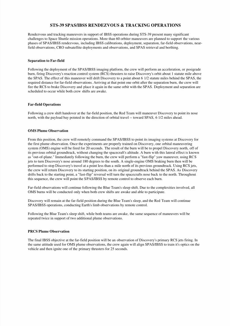
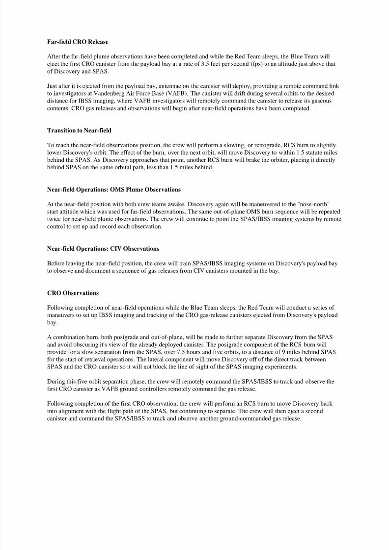
Far-field CRO Release
After the far-field plume observations have been completed and while the Red Team sleeps, the Blue Team will
eject the first CRO canister from the payload bay at a rate of 3.5 feet per second (fps) to an altitude just above that
of Discovery and SPAS.
Just after it is ejected from the payload bay, antennae on the canister will deploy, providing a remote command link
to investigators at Vandenberg Air Force Base (VAFB). The canister will drift during several orbits to the desireddistance for IBSS imaging, where VAFB investigators will remotely command the canister to release its gaseous
contents. CRO gas releases and observations will begin after near-field operations have been completed.
Transition to Near-field
To reach the near-field observations position, the crew will perform a slowing, or retrograde, RCS burn to slightly
lower Discovery's orbit. The effect of the burn, over the next orbit, will move Discovery to within 1 5 statute miles
behind the SPAS. As Discovery approaches that point, another RCS burn will brake the orbiter, placing it directly
behind SPAS on the same orbital path, less than 1.5 miles behind.
Near-field Operations: OMS Plume Observations
At the near-field position with both crew teams awake, Discovery again will be maneuvered to the "nose-north"
start attitude which was used for far-field observations. The same out-of-plane OMS burn sequence will be repeated
twice for near-field plume observations. The crew will continue to point the SPAS/IBSS imaging systems by remote
control to set up and record each observation.
Near-field Operations: CIV Observations
Before leaving the near-field position, the crew will train SPAS/IBSS imaging systems on Discovery's payload bay
to observe and document a sequence of gas releases from CIV canisters mounted in the bay.
CRO Observations
Following completion of near-field operations while the Blue Team sleeps, the Red Team will conduct a series of
maneuvers to set up IBSS imaging and tracking of the CRO gas-release canisters ejected from Discovery's payload
bay.
A combination burn, both posigrade and out-of-plane, will be made to further separate Discovery from the SPAS
and avoid obscuring it's view of the already deployed canister. The posigrade component of the RCS burn will
provide for a slow separation from the SPAS, over 7.5 hours and five orbits, to a distance of 9 miles behind SPAS
for the start of retrieval operations. The lateral component will move Discovery off of the direct track between
SPAS and the CRO canister so it will not block the line of sight of the SPAS imaging experiments.
During this five-orbit separation phase, the crew will remotely command the SPAS/IBSS to track and observe the
first CRO canister as VAFB ground controllers remotely command the gas release.
Following completion of the first CRO observation, the crew will perform an RCS burn to move Discovery back
into alignment with the flight path of the SPAS, but continuing to separate. The crew will then eject a second
canister and command the SPAS/IBSS to track and observe another ground-commanded gas release.

8/8/2019 STS-39 Press Kit
http://slidepdf.com/reader/full/sts-39-press-kit 34/48
SPAS/IBSS Retrieval
After separating to more than 9 statute miles and with both crew shifts awake again, a retrograde burn will slightly
lower Discovery's orbit to overtake the SPAS/IBSS. Several course adjustment burns may be conducted as
Discovery nears it's target, in order to arrive directly in front of the SPAS on the same flight path. The crew then
will manually maneuver Discovery to within range of the remote manipulator system for capture.
8/8/2019 STS-39 Press Kit
http://slidepdf.com/reader/full/sts-39-press-kit 35/48
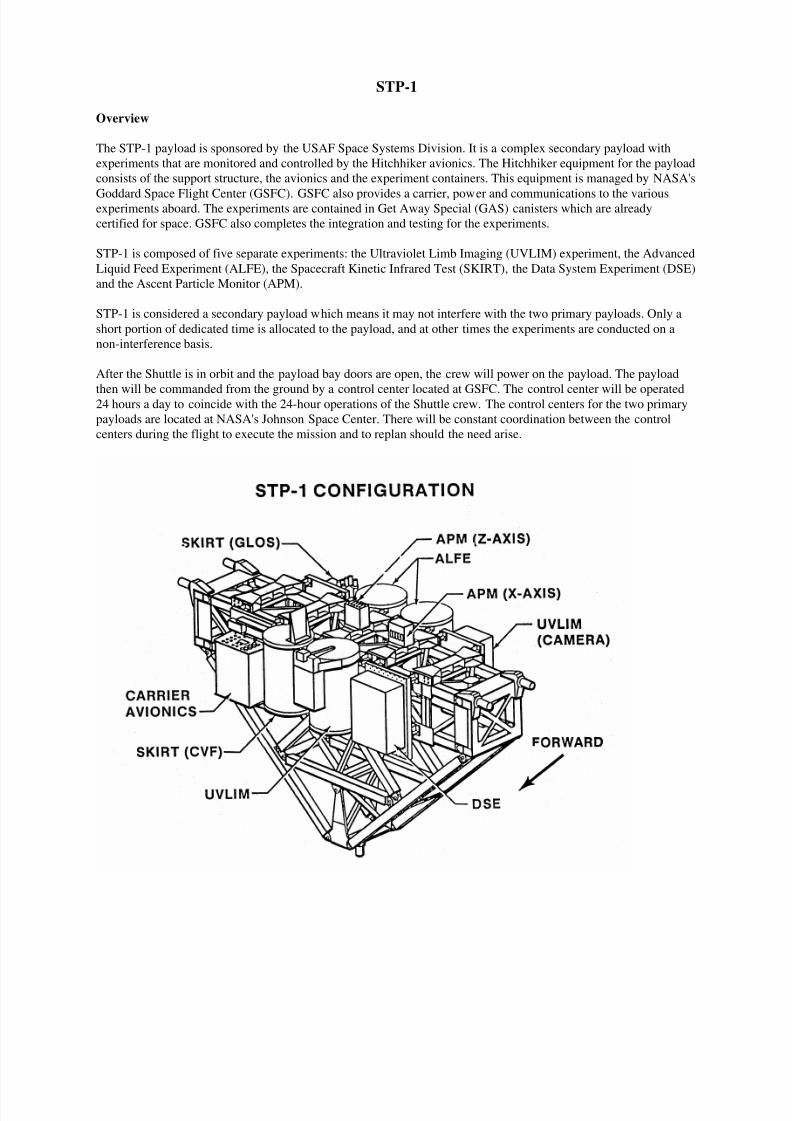
STP-1
Overview
The STP-1 payload is sponsored by the USAF Space Systems Division. It is a complex secondary payload with
experiments that are monitored and controlled by the Hitchhiker avionics. The Hitchhiker equipment for the payload
consists of the support structure, the avionics and the experiment containers. This equipment is managed by NASA's
Goddard Space Flight Center (GSFC). GSFC also provides a carrier, power and communications to the variousexperiments aboard. The experiments are contained in Get Away Special (GAS) canisters which are already
certified for space. GSFC also completes the integration and testing for the experiments.
STP-1 is composed of five separate experiments: the Ultraviolet Limb Imaging (UVLIM) experiment, the Advanced
Liquid Feed Experiment (ALFE), the Spacecraft Kinetic Infrared Test (SKIRT), the Data System Experiment (DSE)
and the Ascent Particle Monitor (APM).
STP-1 is considered a secondary payload which means it may not interfere with the two primary payloads. Only a
short portion of dedicated time is allocated to the payload, and at other times the experiments are conducted on a
non-interference basis.
After the Shuttle is in orbit and the payload bay doors are open, the crew will power on the payload. The payload
then will be commanded from the ground by a control center located at GSFC. The control center will be operated24 hours a day to coincide with the 24-hour operations of the Shuttle crew. The control centers for the two primary
payloads are located at NASA's Johnson Space Center. There will be constant coordination between the control
centers during the flight to execute the mission and to replan should the need arise.
8/8/2019 STS-39 Press Kit
http://slidepdf.com/reader/full/sts-39-press-kit 36/48
Hitchhiker Project
The Hitchhiker Project, operated by Goddard Space Flight Center (GSFC) in Greenbelt, MD, provides for
accommodation of small payloads in the Shuttle payload bay. The Hitchhiker payload for STS-39 is called Space
Test Payload-1 (STP-1) and consists of a Hitchhiker cross-bay carrier with five experiments. The carrier hardware
includes the cross-bay structure, carrier avionics unit, mounting plates, canisters and a motorized canister door.
STP-1 is sponsored by the U.S. Air Force Space Systems Division.
Hitchhiker was designed and built at Goddard and will be operated from a control center at GSFC during the
mission. The five experiments on STP-1 are: The Hitchhiker Project is operated by GSFC for the NASA Office of
Space Flight. Payloads are provided thermally controlled mounting surfaces or sealed pressurizable canisters,
orbiter power, command and data interfaces.
The last Hitchhiker mission was in 1986, and the next after STS-39 will be in August 1992, followed by another in
October of that year.
GSFC Project Manager and Deputy Project Manager are Theodore Goldsmith and Steven Dunker. Chuck Chidekel,
also of Goddard, is Integration Manager. The USAF STP-1 Program Manager is Capt. Hau Tran, and NASA
Headquarters Program Manager is Edward James.
Ultraviolet Limb Imaging (UVLIM) Experiment
The objective of the Ultraviolet Limb Imaging experiment, sponsored by the Naval Research Laboratory in
Washington D .C., is to measure the vertical and geographic distribution of the ultraviolet airglow in the wavelength
region from 575 angstroms to 1900 angstroms.
These measurements will be used to determine the daily and seasonal variation of the composition of the ionosphere
and neutral atmosphere between the altitudes of 100 and 500 kilometers. The UVLIM experiment requires a 5 cubic
foot canister with a motorized door and a mounting plate to house a 35 mm aspect camera. The camera will be
aligned with the experiment aperture plate to provide simultaneous data which will be correlated with post flight
data in determining point location.
The experiment uses an extreme ultraviolet imaging spectrometer with a two dimensional detector to make images
of the horizon from the airglow emissions which characterize the composition of the ionosphere. The far ultraviolet
spectrometer measures emissions indicative of the temperature and composition of the neutral atmosphere.
Advanced Liquid Feed Experiment (ALFE)
The next generation of spacecraft and space tugs may be one step closer to autonomous operation and longer life
due to the technology to be demonstrated in space by the Advanced Liquid Feed Experiment (ALFE). The space
flight experiment is designed to evaluate the performance of key components of an advanced spacecraft propulsion
system designed and built by the McDonnell Douglas Astronautics Company (MDAC) under contract to the Phillips
Laboratory's Astronautics Directorate.
ALFE will provide the first space flight demonstration of an electronic pressure regulator and a series of ultrasonic
propellant level and flow sensing systems. These components will provide the capability to remotely and
electronically control the pressurization schedule of spacecraft propellant tanks to accurately gauge the available on-
board propellants and to reliably track the propellant usage throughout the mission. The experiment also will
demonstrate the capability to integrate all storable propellant on-board the spacecraft by transferring attitude control
system propellants into the main engine tanks and vice versa.
The experiment is designed to use commercially available components to build two hardware modules weighing
approximately 250 pounds each. The first module is an electronic package which will function as the remote test
8/8/2019 STS-39 Press Kit
http://slidepdf.com/reader/full/sts-39-press-kit 37/48
conductor aboard the Shuttle. It contains an on-board computer and associated electronics necessary for performing
the experiment and recording the data.
The module will provide the command and control for the experiment. It also will provide the communication link
to transfer experiment telemetry and video signals to the ground based operator located at NASA's Goddard Space
Flight Center (GSFC).
The second module is the fluid system module. It contains two test tanks, an electronic pressure regulator, anultrasonic liquid gauging system and the associated instrumentation, pumps and valves. The items of interest are the
test tanks, the electronic pressure regulator and the ultrasonic liquid gauging system.
The test tanks are made of Plexiglas and are scaled to represent a 1/4 scale of the actual system. Internally, each of
these tanks is fitted with a liquid acquisition device for liquid positioning in the low gravity environment of space,
and a screen device to preclude the ingestion of gas bubble into the lines. During the experiment, various quantities
of fluid will be transferred between two tanks to simulate a hypothetical resupply scenario in space.
The electronic pressure regulator, built by Parker Hannifin of Irvine, CA, will control the pressure of the test tank
during flight. It has a unique capability to provide a smooth ramp-up of tank pressure when commanded in contrast
with the typical burst disk system. The regulator also has the capability to control the downstream pressure to
different pressure settings.
This will enable better management of the limited quantity of the precious pressurized gas carried by the spacecraft.
The ultrasonic liquid gauging system, supplied by Panametrics in Waltham, Mass., will provide an advanced
approach to measure and track the liquid propellant usage. The system consists of a group of six ultrasonic point
sensors and an ultrasonic flow cell. The point sensors, using the pulse-echo effect, measure the time delays for the
ultrasonic pulses and their echoes to transit through the fluid to the gas-liquid interface. From these time
measurements, the amount of the liquid contained within the tank can be calculated. Using a similar approach, the
ultrasonic flow cell measures the time delay between two simultaneous ultrasonic pulses along a fluid line to
calculate the propellant flow.
When flown, the ALFE on-board computer will accept commands from the ground based operator located at
NASA's GSFC and will configure the payload for the desired test sequence. An internal wide angle television
camera will record the fluid settling characteristics under various acceleration loads.
Experiment data will be both stored on-board in the electronic module and transmitted to the ground based operator.
The results will be used in further updating the design of the advanced spacecraft feed system.
Spacecraft Kinetic Infrared Test (SKIRT)
The Spacecraft Kinetic Infrared Test (SKIRT), sponsored by Phillips Laboratory's Geophysics Directorate, consists
of two separate and independent components.
The Gaseous Luminosity of Optical Surface (GLOS) consists of infrared, visible and ultraviolet radiometers
combined into one package weighing 50 pounds. The Circular Variable Filter (CVF) is a solid nitrogen cooled
infrared spectrometer/radiometer mounted in a sealed canister with an aperture in the top plate. A motor driven
cover is commanded open and closed on-orbit to cover the aperture as needed. A "glow plate" attached to the top
plate provides a surface for impingement of the residual atmosphere to produce the glow which is then observed by
the spectrometer. CVF weighs approximately 150 pounds with cryogen.
The experiment objective is to obtain infrared spectral measurements of the Shuttle glow at resolutions and
sensitivity that will allow identification of the chemical species associated with this phenomenon. Since the Shuttle
glow effect is thought to be caused by the impact of atomic oxygen on the orbiter surfaces, it is only necessary that
surfaces near the SKIRT field-of-view be exposed to ram (direction) at various times during the mission.
8/8/2019 STS-39 Press Kit
http://slidepdf.com/reader/full/sts-39-press-kit 38/48
Ascent Particle Monitor (APM)
The Ascent Particle Monitor (APM), sponsored by USAF Space Systems Division's Operating Location detachment
in Houston Texas, consists of a small box with a fixed door and a movable door mounted in a clamshell
arrangement atop an aluminum housing. Each door contains six coupon holders into which selected passive witness
samples are installed. The door is closed preflight to protect the coupons from the environment. It is opened after
ground operations are completed and the payload bay doors are about to be closed in preparation for launch. A
motor/gearbox assembly, two battery packs, launch detection circuitry and door opening circuitry are containedwithin the aluminum housing of the unit. The electric motor is used to open and close the door so that particles can
be collected at specific times during Shuttle ascent. An internal timing circuit set prior to installation of the APM
into the orbiter payload bay to control the door movement. The timer circuit is acoustically actuated by orbiter main
engine start.
The concept of the APM experiment evolved as a direct response to concerns by the spacecraft community about
the fallout of particles in the Shuttle orbiter payload bay during the ascent portion of the missions. Particulate
contaminants on Shuttle bay surfaces and on surfaces of payloads in the cargo bay may be released during launch
and ascent by vibroacoustic, gravitational and aerodynamic forces. These particles can be deposited on surfaces
from which they were released or on other surfaces depending on location acceleration and velocity vectors with
respect to such surfaces.
Many analytical models of particle redistribution have been made using assumed ascent forces during launch, but
most models are based on uniform redistribution of particles. Insufficient experiment data exist on particle fallout
and deposition during Shuttle ascent to verify current models. The understanding of particle redistribution on
surfaces and releases of particles into the field of view of instruments incorporating critical sensors is important in
view of the influence the particles may have on the properties of the surfaces on which they are deposited and on the
optical degradation of the environment into which they may escape. Some of the effects of particles on surfaces and
in the environment are physical obscuration of the surface, scattering of radiation which changes the transmitting or
reflecting properties, increased diffuse reflection of the surface, and emission of radiation by the particles which
may be detrimental to certain sensors.
The first APM flew on the STS-28 mission and the flight coupons were analyzed in the Materials Science
Laboratory of the Aerospace Corporation in Los Angeles, Calif. Various analytical techniques were used to evaluate
the contaminants, including optical and scanning electron microscopy, infrared spectroscopy and energy dispersive
X-ray spectroscopy. The coupons also were examined at NASA's Goddard Space Flight Center at Greenbelt, MD.,
using bidirectional reflectance distribution function scatter measurements. The APM also flew on STS-31 (Hubble
Space Telescope), and is manifested on STS-37 (Gamma Ray Observatory payload).
Data System Experiment (DSE)
The Data System Experiment (DSE), sponsored by NASA's Goddard Space Flight Center in Greenbelt, MD.,
consists of a MILVAX computer, Erasable Optical Disk, and associated simulators and interfaces. The simulators
would generate data to be used to exercise the computer and the optical disk.
The objective of the DSE is to evaluate the performance of the computer and disk in a micro gravity environment.
The optical disk system stem consists of an erasable optical disk drive unit and a removable cartridge media. Both
are designed for reliable use under a variety of environmental conditions.
8/8/2019 STS-39 Press Kit
http://slidepdf.com/reader/full/sts-39-press-kit 39/48

8/8/2019 STS-39 Press Kit
http://slidepdf.com/reader/full/sts-39-press-kit 40/48
MULTI-PURPOSE EXPERIMENT CANISTER (MPEC)
The Multi-Purpose Experiment Canister (MPEC) carries a classified experiment sponsored by the USAF Space
Systems Division (SSD). The canister, a modified Get Away Special (GAS) container, is mounted on a beam
attached to the starboard sidewall of orbiter cargo bay 6. The modified canister includes a 9-inch extension
containing an ejection kit, electronics and a full diameter motorized door assembly.
The experiment is scheduled to be deployed from the cargo bay on the last day of the mission. However,deployment can occur earlier on a contingency basis.
The crew provides power to the MPEC via the standard switch panel located in the crew compartment. The crew
will send a command to open the canister door and, after verifying that the door is open, will arm the ejection
mechanism and send the deployment command. The experiment is ejected with a relative velocity of about 2.7 ft/sec
by a spring mechanism. After ejection, the canister door will be closed and power removed from the canister.

8/8/2019 STS-39 Press Kit
http://slidepdf.com/reader/full/sts-39-press-kit 41/48
CLOUDS 1A
The overall objective of the CLOUDS-1A program is to quantify the variation in apparent cloud cover as a function
of the angle at which clouds of various types are viewed.
The CLOUDS-1A experiment is stowed in a middeck locker and consists of a Nikon F3/T camera assembly and
film. On-orbit, a crew member will take a series of high resolution photographs of individual cloud scenes,
preferably high "wispy" cirrus clouds, over a wide range of viewing angles.
8/8/2019 STS-39 Press Kit
http://slidepdf.com/reader/full/sts-39-press-kit 42/48
RADIATION MONITORING EQUIPMENT-III
Radiation Monitoring Equipment-III (RME-III) measures the rate and dosage of ionizing radiation to the crew at
different locations throughout the orbiter cabin. The hand-held instrument measures gamma ray, electron, neutron
and proton radiation and calculates the amount of exposure. The information is stored in memory modules for post-
flight analysis.
RME-III will be stored in a middeck locker during flight except for when it is turned on and when memory modulesare replaced every 2 days. It will be activated as soon as possible after achieving orbit and will operate throughout
the flight. To activate the instrument, a crew member will enter the correct mission elapsed time.
The instrument contains a liquid crystal display for real-time data readings and a keyboard for function control. It
has four zinc-air batteries and five AA batteries in each replaceable memory module and two zinc-air batteries in the
main module.
RME-III, which has flown on STS-31 and STS-41, is the current configuration, replacing the earlier RME-I and
RME-II units.
The Department of Defense, in cooperation with NASA, sponsors the data gathering instrument.
8/8/2019 STS-39 Press Kit
http://slidepdf.com/reader/full/sts-39-press-kit 43/48
Edited by Richard W. Orloff, 01/2001/Page 43
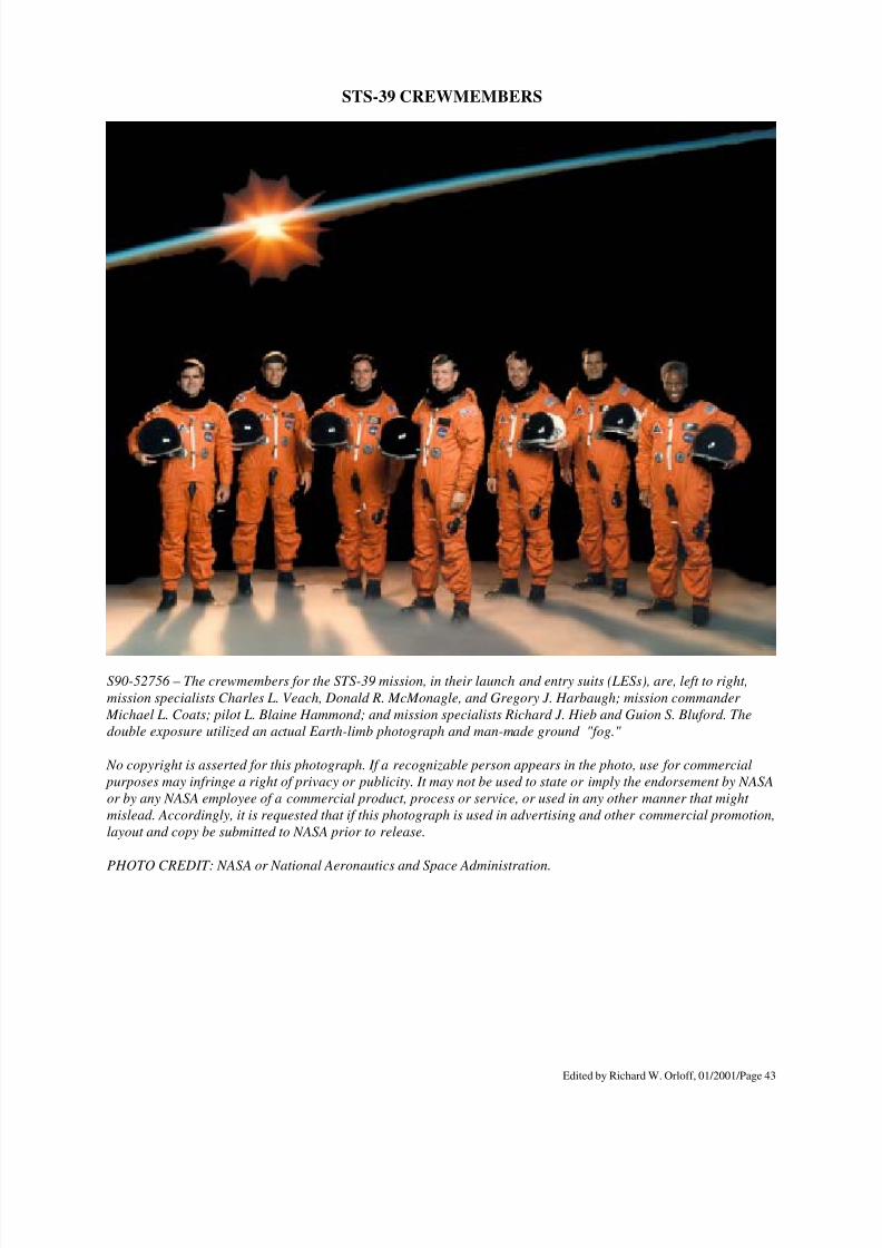
STS-39 CREWMEMBERS
S90-52756 – The crewmembers for the STS-39 mission, in their launch and entry suits (LESs), are, left to right,
mission specialists Charles L. Veach, Donald R. McMonagle, and Gregory J. Harbaugh; mission commander
Michael L. Coats; pilot L. Blaine Hammond; and mission specialists Richard J. Hieb and Guion S. Bluford. The
double exposure utilized an actual Earth-limb photograph and man-made ground "fog."
No copyright is asserted for this photograph. If a recognizable person appears in the photo, use for commercial
purposes may infringe a right of privacy or publicity. It may not be used to state or imply the endorsement by NASA
or by any NASA employee of a commercial product, process or service, or used in any other manner that might
mislead. Accordingly, it is requested that if this photograph is used in advertising and other commercial promotion,
layout and copy be submitted to NASA prior to release.
PHOTO CREDIT: NASA or National Aeronautics and Space Administration.
8/8/2019 STS-39 Press Kit
http://slidepdf.com/reader/full/sts-39-press-kit 44/48
BIOGRAPHICAL DATA
Michael L. Coats, 45, Capt., USN, will serve as commander. Selected as an astronaut in 1978, he considers
Riverside, CA, his hometown. STS-39 will be Coats' third space flight.
Coats was pilot on STS-41D, launched Aug. 30, 1984, the maiden flight of Discovery. Coats next commanded
mission STS-29 aboard Discovery, launched March 13, 1989, to deploy a Tracking and Data Relay Satellite.
Coats graduated from Ramona High School, Riverside, in 1964, received a bachelor of science from the U.S. Naval
Academy in 1968; a master of science in the administration of science and technology from George Washington
University in 1977; and a master of science in aeronautical engineering from the U.S. Naval Postgraduate School in
1979.
He was designated a naval aviator upon graduation from Annapolis in 1969 and was assigned to Attack Squadron
192 aboard the USS Kitty Hawk for 2 years, flying 315 combat missions in Southeast Asia. He then served as a
flight instructor with the A-7E Readiness Training Squadron at the Naval Air Station in Lemoore, CA, for a year
before attending the Naval Test Pilot School. Afterward, he was project officer and test pilot for the A-7 and A-4
aircraft for 2 years before becoming a flight instructor at the Test Pilot School in 1976.
Coats has logged more than 5,000 hours of flying time in more than 28 different aircraft and 264 hours in space.
L. Blaine Hammond Jr., 38, Major, USAF, will serve as Pilot. Selected as an astronaut in 1984, Hammond was
born in Savannah, Ga., and will make his first space flight.
Hammond graduated from Kirkwood High School, Kirkwood, Mo., in 1969; received a bachelor of science in
engineering science and mechanics from the U.S. Air Force Academy in 1973; and received a master of science in
engineering science and mechanics from the Georgia Institute of Technology in 1974.
Hammond earned his wings at Reese Air Force Base, Texas, in 1975 and was assigned to the 496th Tactical Fighter
Squadron, Hahn Air Base, Germany, flying the F-4E. In 1979, he spent a year at Williams Air Force Base, Ariz.,
flying the F-5B/E/F and training foreign students. Hammond then attended the Empire Test Pilot School at A&AEE
Boscombe Down, England. He returned to Edwards Air Force Base in 1982 and was assigned as an instructor at the
Air Force Test Pilot School, a position he held at the time of his selection by NASA.
Hammond has logged more than 3,100 hours flying 15 different American and 10 different English aircraft.
Gregory J. Harbaugh, 34, will serve as Mission Specialist 1 (MS1). Harbaugh, selected as an astronaut in 1987,
considers Willoughby, Ohio, to be his hometown and will make his first space flight.
Harbaugh graduated from Willoughby South High School in 1974; received a bachelor of science in aeronautical
engineering from Purdue University in 1978; and received a master of science in physical sciences from the
University of Houston-Clear Lake in 1986.
Harbaugh came to NASA upon his graduation from Purdue and served in engineering and management positions at
JSC until his selection as an astronaut. Harbaugh supported Shuttle operations in Mission Control for most flightsfrom STS-1 through STS-51L, working as a Data Processing Systems (DPS) flight controller and later as a Shuttle
Planning and Analysis Manager, the senior flight controller interface with the engineering community. He also has a
commercial pilot's license and has logged more than 1,000 hours flying time.
8/8/2019 STS-39 Press Kit
http://slidepdf.com/reader/full/sts-39-press-kit 45/48
BIOGRAPHICAL DATA
Donald R. McMonagle, 38, Lt. Col., USAF, will serve as Mission Specialist 2 (MS2). Selected as an astronaut in
1987, he was born in Flint, Mich., and will make his first space flight.
McMonagle graduated from Hamady High School, Flint, Mich., in 1970; received a bachelor of science in
astronautical engineering from the Air Force Academy in 1974; and a master of science in mechanical engineering
from California State University-Fresno in 1985.
He completed pilot training on the F-4 in 1975 and was assigned a year-long tour of duty at Kunsan Air Base, South
Korea. He returned to Holloman AFB, N.M., in 1977 for training on the F-15, and, in 1979, was assigned as an F-15
instructor at Luke AFB, Ariz. In 1981, he attended the Air Force Test Pilot School and graduated as the outstanding
pilot of his class. From 1982-1985, he was the operations officer and test pilot for the Advanced Fighter Technology
Integration (AFTI) F-16. He then attended the Air Command and Staff College at Maxwell AFB, AL., for 1 year
before being assigned as operations officer for the 6513th Test Squadron at Edwards AFB, CA, where he was
stationed at the time of his selection by NASA.
McMonagle has logged more than 3,400 hours flying time in a variety of aircraft.
Guion S. Bluford, 48, Col., USAF, will serve as Mission Specialist 3 (MS3). Selected as an astronaut in 1979,Bluford was born in Philadelphia, Pa., and will make his third space flight.
Bluford graduated from Overbrook High School, Philadelphia, in 1960; received a bachelor of science in aerospace
engineering from Pennsylvania State University in 1964; received a master of science in the same subject from the
Air Force Institute of Technology in 1974; received a doctorate in aerospace engineering with a minor in laser
physics from the Air Force Institute of Technology in 1978; and received a master of business administration from
the University of Houston-Clear Lake in 1987.
He served as a mission specialist on STS-8, launched Aug. 30, 1983, the third flight of Challenger and first mission
with a night launch and landing. During the flight, the crew deployed the Indian National Satellite (INSAT-1B) and
operated the remote manipulator system with a test article. His next flight was as a mission specialist aboard
Challenger on STS 61-A, launched Oct. 30, 1985, with the German D-1 Spacelab.
Bluford has logged more than 314 hours in space.
C. Lacy Veach, 46, will serve as Mission Specialist 4 (MS4). Selected as an astronaut in 1984, Veach considers
Honolulu his hometown and will make his first space flight.
Veach graduated from Punahou School in 1962 and received a bachelor of science in engineering management from
the Air Force Academy in 1966.
Veach was commissioned in the Air Force upon graduation from the Academy and received his pilot wings in 1967.
For 14 years, he served as a fighter pilot with a variety of assignments in the United States and overseas, including a
275-mission combat tour in Southeast Asia and 2 years with the Air Force Demonstration Squadron, the
Thunderbirds. Veach left active duty in 1981, but continues to fly with the Texas Air National Guard.
He began work at NASA in 1982 as an engineer and research pilot, serving as an instructor pilot in the Shuttle
Training Aircraft until his selection as an astronaut.
He has logged more than 4,500 flying hours.

8/8/2019 STS-39 Press Kit
http://slidepdf.com/reader/full/sts-39-press-kit 46/48
BIOGRAPHICAL DATA
Richard J. Hieb, 35, will serve as Mission Specialist 5 (MS5). Selected as an astronaut in 1986, he considers
Jamestown, N. D., his hometown and will make his first space flight.
Hieb graduated from Jamestown High School in 1973; received a bachelor of arts in math and physics from
Northwest Nazarene College in 1977; and received a master of science in aerospace engineering from the University
of Colorado in 1979.
Hieb began work for NASA after graduating from the University of Colorado, serving in the crew procedures
development and crew activity planning areas. He worked in Mission Control for ascent during STS-1 and
specialized in rendezvous and proximity operations for numerous subsequent flights.
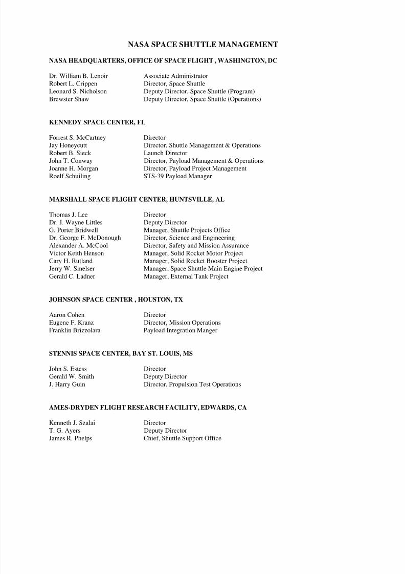
8/8/2019 STS-39 Press Kit
http://slidepdf.com/reader/full/sts-39-press-kit 47/48
NASA SPACE SHUTTLE MANAGEMENT
NASA HEADQUARTERS, OFFICE OF SPACE FLIGHT , WASHINGTON, DC
Dr. William B. Lenoir Associate Administrator
Robert L. Crippen Director, Space Shuttle
Leonard S. Nicholson Deputy Director, Space Shuttle (Program)
Brewster Shaw Deputy Director, Space Shuttle (Operations)
KENNEDY SPACE CENTER, FL
Forrest S. McCartney Director
Jay Honeycutt Director, Shuttle Management & Operations
Robert B. Sieck Launch Director
John T. Conway Director, Payload Management & Operations
Joanne H. Morgan Director, Payload Project Management
Roelf Schuiling STS-39 Payload Manager
MARSHALL SPACE FLIGHT CENTER, HUNTSVILLE, AL
Thomas J. Lee Director
Dr. J. Wayne Littles Deputy Director
G. Porter Bridwell Manager, Shuttle Projects Office
Dr. George F. McDonough Director, Science and Engineering
Alexander A. McCool Director, Safety and Mission Assurance
Victor Keith Henson Manager, Solid Rocket Motor Project
Cary H. Rutland Manager, Solid Rocket Booster Project
Jerry W. Smelser Manager, Space Shuttle Main Engine Project
Gerald C. Ladner Manager, External Tank Project
JOHNSON SPACE CENTER , HOUSTON, TX
Aaron Cohen Director
Eugene F. Kranz Director, Mission Operations
Franklin Brizzolara Payload Integration Manger
STENNIS SPACE CENTER, BAY ST. LOUIS, MS
John S. Estess Director
Gerald W. Smith Deputy Director
J. Harry Guin Director, Propulsion Test Operations
AMES-DRYDEN FLIGHT RESEARCH FACILITY, EDWARDS, CA
Kenneth J. Szalai Director
T. G. Ayers Deputy Director
James R. Phelps Chief, Shuttle Support Office
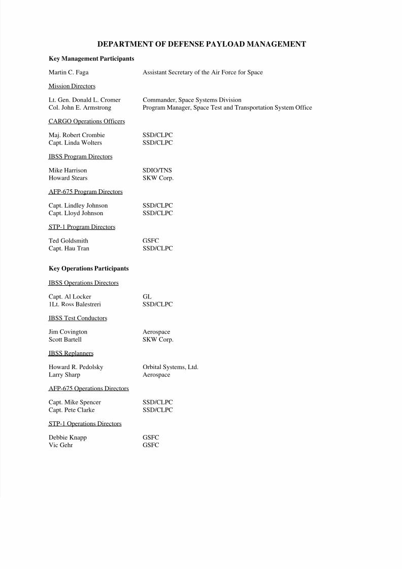
8/8/2019 STS-39 Press Kit
http://slidepdf.com/reader/full/sts-39-press-kit 48/48