
Selected issues of prestressed concrete...
13
SZYMON KAŹMIERCZAK * SELECTED ISSUES OF PRESTRESSED CONCRETE CONTAINMENT TANKS FOR THE STORAGE OF LIQUEFIED GASES DESIGN IN ACCORDANCE WITH EN 14620 WYBRANE ZAGADNIENIA PROJEKTOWANIA ZBIORNIKÓW Z BETONU SPRĘŻONEGO DO MAGAZYNOWANIA SKROPLONYCH GAZÓW W UJĘCIU EN 14620 Abstract In 2014, a new tank for the storage of liquefied ammonia (capacity 22 000 m 3 ) was built for the chemical industry company ‘Grupa Azoty S.A.’. The LNG terminal in Świnoujście, where two large capacity containers (160 000 m 3 each) were built, is almost finished (2015). In both cases, prestressed concrete was used to build a secondary (outer) containment tank.This paper is devoted to general concepts and design considerations for secondary cylindrical, concrete containers for the storage of refrigerated, liquefied gases with temperatures between 0°C and –165°C, according to EN 14620. Keywords: prestressed concrete, cylindrical storage tanks, liquefied gases, low temperature Streszczenie W 2014 roku przedsiębiorstwo przemysłu chemicznego Grupa Azoty S.A. oddało do użytku nowy zbior- nik do magazynowania skroplonego amoniaku o pojemności 22 tys. m 3 . Prace związane z budową ter- minala LNG w Świnoujściu, gdzie powstały dwa zbiorniki o dużej pojemności (160 tys. m 3 każdy), są niemal ukończone (2015). W obu wymienionych przypadkach konstrukcję zbiornika zewnętrznego wy- konano z betonu sprężonego. Artykuł przedstawia ogólne koncepcje i zasady projektowania zewnętrznych walcowych zbiorników z betonu do magazynowania skroplonych gazów o temperaturach pomiędzy 0°C i –165°C, według normy EN 14620. Słowa kluczowe: beton sprężony, zbiorniki cylindryczne, skroplone gazy, niska temperatura DOI: 10.4467/2353737XCT.15.166.4341 * Ph.D. Eng., Szymon Kaźmierczak, Institute of Building Materials and Structures, Faculty of Civil Engineering, Cracow University of Technology.
Transcript of Selected issues of prestressed concrete...
SZYMON KAŹMIERCZAK*
SELECTED ISSUES OF PRESTRESSED CONCRETE CONTAINMENT TANKS FOR THE STORAGE
OF LIQUEFIED GASES DESIGN IN ACCORDANCE WITH EN 14620
WYBRANE ZAGADNIENIA PROJEKTOWANIA ZBIORNIKÓW Z BETONU SPRĘŻONEGO
DO MAGAZYNOWANIA SKROPLONYCH GAZÓW W UJĘCIU EN 14620
A b s t r a c t
In 2014, a new tank for the storage of liquefied ammonia (capacity 22 000 m3) was built for the chemical industry company ‘Grupa Azoty S.A.’. The LNG terminal in Świnoujście, where two large capacity containers (160 000 m3 each) were built, is almost finished (2015). In both cases, prestressed concrete was used to build a secondary (outer) containment tank.This paper is devoted to general concepts and design considerations for secondary cylindrical, concrete containers for the storage of refrigerated, liquefied gases with temperatures between 0°C and –165°C, according to EN 14620.
Keywords: prestressed concrete, cylindrical storage tanks, liquefied gases, low temperature
S t r e s z c z e n i e
W 2014 roku przedsiębiorstwo przemysłu chemicznego Grupa Azoty S.A. oddało do użytku nowy zbior-nik do magazynowania skroplonego amoniaku o pojemności 22 tys. m3. Prace związane z budową ter-minala LNG w Świnoujściu, gdzie powstały dwa zbiorniki o dużej pojemności (160 tys. m3 każdy), są niemal ukończone (2015). W obu wymienionych przypadkach konstrukcję zbiornika zewnętrznego wy-konano z betonu sprężonego. Artykuł przedstawia ogólne koncepcje i zasady projektowania zewnętrznych walcowych zbiorników z betonu do magazynowania skroplonych gazów o temperaturach pomiędzy 0°C i –165°C, według normy EN 14620.
Słowa kluczowe: beton sprężony, zbiorniki cylindryczne, skroplone gazy, niska temperatura
DOI: 10.4467/2353737XCT.15.166.4341* Ph.D. Eng., Szymon Kaźmierczak, Institute of Building Materials and Structures, Faculty of Civil
Engineering, Cracow University of Technology.
102
1. Introduction
The current version of standard EN 14620[1] specifies the recommendations for materials, design rules, construction details and installation principles for above ground containment tanks for the storage of liquefied, refrigerated gases.
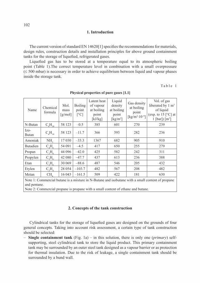
Liquefied gas has to be stored at a temperature equal to its atmospheric boiling point (Table 1).The correct temperature level in combination with a small overpressure (≤ 500 mbar) is necessary in order to achieve equilibrium between liquid and vapour phases inside the storage tank.
T a b l e 1
Physical properties of pure gases [1.1]
Name Chemical formula
Mol. mass
[g/mol]
Boiling point[°C]
Latent heat of vapour at boiling
point[kJ/kg]
Liquid density
at boiling point
[kg/m3]
Gas density at boiling
point[kg/m3⋅10–8]
Vol. of gas liberated by 1 m3
of liquid (exp. to 15 [°C] at
1 [bar]) [m3]N-Butan C4H10 58 123 –0.5 385 601 270 239Izo-Butan C4H10 58 123 –11.7 366 593 282 236
Amoniak NH3 17 030 –33.3 1367 682 905 910Butadien C4H6 54 091 –4.5 417 650 255 279Propan C3H8 44 096 –42.0 425 582 242 311Propylen C3H6 42 080 –47.7 437 613 236 388Etan C2H6 30 069 –88.6 487 546 205 432Etylen C2H4 28 054 –103.7 482 567 208 482Metan CH4 16 043 –161.5 509 422 181 630Note 1: Commercial butane is a mixture in N-Butane and isobutane with a small content of propane and pentane.Note 2: Commercial propane is propane with a small content of ethane and butane.
2. Concepts of the tank construction
Cylindrical tanks for the storage of liquefied gases are designed on the grounds of four general concepts. Taking into account risk assessment, a certain type of tank construction should be selected: – Single containment tank (Fig. 1a) – in this solution, there is only one (primary) self-
supporting, steel cylindrical tank to store the liquid product. This primary containment tank may be surrounded by an outer steel tank designed as a vapour barrier or as protection for thermal insulation. Due to the risk of leakage, a single containment tank should be surrounded by a bund wall.
103
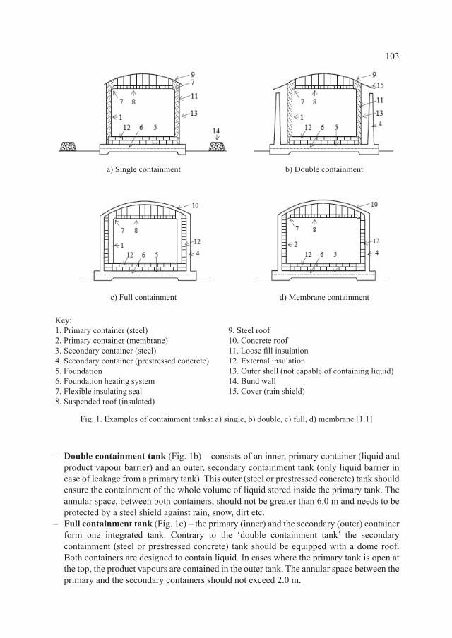
– Double containment tank (Fig. 1b) – consists of an inner, primary container (liquid and product vapour barrier) and an outer, secondary containment tank (only liquid barrier in case of leakage from a primary tank). This outer (steel or prestressed concrete) tank should ensure the containment of the whole volume of liquid stored inside the primary tank. The annular space, between both containers, should not be greater than 6.0 m and needs to be protected by a steel shield against rain, snow, dirt etc.
– Full containment tank (Fig. 1c) – the primary (inner) and the secondary (outer) container form one integrated tank. Contrary to the ‘double containment tank’ the secondary containment (steel or prestressed concrete) tank should be equipped with a dome roof. Both containers are designed to contain liquid. In cases where the primary tank is open at the top, the product vapours are contained in the outer tank. The annular space between the primary and the secondary containers should not exceed 2.0 m.
Key:1. Primary container (steel)2. Primary container (membrane)3. Secondary container (steel)4. Secondary container (prestressed concrete)5. Foundation6. Foundation heating system7. Flexible insulating seal8. Suspended roof (insulated)
Fig. 1. Examples of containment tanks: a) single, b) double, c) full, d) membrane [1.1]
a) Single containment b) Double containment
c) Full containment d) Membrane containment
9. Steel roof 10. Concrete roof11. Loose fill insulation12. External insulation13. Outer shell (not capable of containing liquid)14. Bund wall15. Cover (rain shield)
104
– Membrane tank (Fig. 1d) – consists of a thin steel membrane and load-bearing thermal insulation working together with a concrete container equipped with a dome roof. In the case of membrane leakage, the secondary concrete tank should be able to hold liquid and the product vapours.
3. Liquid tightness
The prestressed concrete secondary tank should ensure liquid and/or vapour tightness. Liquid leakage through concrete can be prevented in two ways [1.3]:– Liners (steel plates) or reinforced/unreinforced polymer coatings may be used as a liquid
(or vapour) barrier applied on the internal surface of the concrete. If concrete cracking occurs, the liner/coating should prove to be capable of ‘bridging’a gap equal to 120% of the calculated crack width.
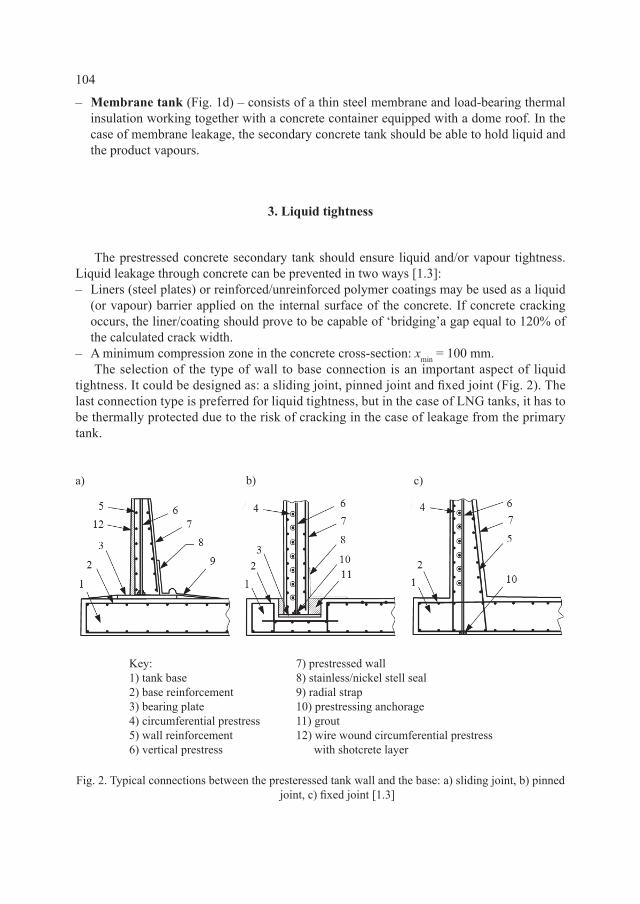
– A minimum compression zone in the concrete cross-section: xmin = 100 mm. The selection of the type of wall to base connection is an important aspect of liquid
tightness. It could be designed as: a sliding joint, pinned joint and fixed joint (Fig. 2). The last connection type is preferred for liquid tightness, but in the case of LNG tanks, it has to be thermally protected due to the risk of cracking in the case of leakage from the primary tank.
Key:1) tank base2) base reinforcement3) bearing plate4) circumferential prestress5) wall reinforcement6) vertical prestress
a) b) c)
Fig. 2. Typical connections between the presteressed tank wall and the base: a) sliding joint, b) pinned joint, c) fixed joint [1.3]
7) prestressed wall8) stainless/nickel stell seal9) radial strap 10) prestressing anchorage11) grout12) wire wound circumferential prestress with shotcrete layer
105
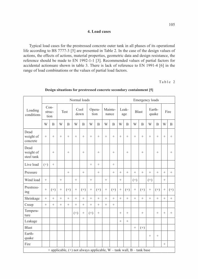
4. Load cases
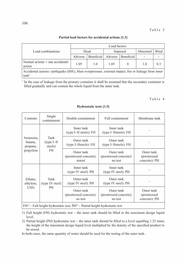
Typical load cases for the prestressed concrete outer tank in all phases of its operational life according to BS 7777-3 [5] are presented in Table 2. In the case of the design values of actions, the effects of actions, material properties, geometric data and design resistance, the reference should be made to EN 1992-1-1 [3]. Recommended values of partial factors for accidental actionsare shown in table 3. There is lack of reference to EN 1991-4 [6] in the range of load combinations or the values of partial load factors.
T a b l e 2
Design situations for prestressed concrete secondary containment [5]
Loading conditions
Normal loads Emergency loads
Con-struc-tion
Test Cool down
Opera-tion
Mainte-nance
Leak-age Blast Earth-
quake Fire
W B W B W B W B W B W B W B W B W B
Dead weight of concrete
+ + + + + + + + + + + + + + + + + +
Dead weight of steel tank
+ + + + + + + + +
Live load (+) + + + +
Pressure + + + + + + + + + + + +
Wind load + + + + + + (+) (+) +
Prestress-ing + (+) + (+) + (+) + (+) + (+) + (+) + (+) + (+) + (+)
Shrinkage + + + + + + + + + + + + + + + + + +
Creep + + + + + + + + + +Tempera-ture (+) + (+) + + + + + + +
Leakage + +
Blast + (+)Earth-quake + +
Fire ++ applicable, (+) not always applicable, W – tank wall, B – tank base
106
T a b l e 3
Partial load factors for accidental actions [1.3]
Load combinationsLoad factors
Dead Imposed Abnormal WindAdverse Beneficial Adverse Beneficial – –
Normal actions + one accidental action 1.05 1.0 1.05 0 1.0 0.3
Accidental actions: earthquake (SSE), blast overpressure, external impact, fire or leakage from inner tank*
* In the case of leakage from the primary container it shall be assumed that the secondary container is filled gradually and can contain the whole liquid from the inner tank.
T a b l e 4
Hydrostatic tests [1.5]
Contents Single containment Double containment Full containment Membrane tank
Ammonia,butane,
propane,propylene
Tank(type I–II
steels)FH
Inner tank(type I–II steels): FH
Inner tank(type I–IIsteels): FH –
Outer tank(type I–IIsteels): FH
Outer tank(type I–IIsteels): FH –
Outer tank(prestressed concrete):
notest
Outer tank(prestressed concrete):
no test
Outer tank(prestressed
concrete): PH
Ethane,ethylene,
LNG
Tank(type IV steel)
PH
Inner tank(type IV steel): PH
Inner tank(type IV steel): PH –
Outer tank(type IV steel): PH
Outer tank(type IV steel): PH –
Outer tank(prestressed concrete):
no test
Outer tank(prestressed concrete):
no test
Outer tank(prestressed
concrete): PH
FH1) – Full height hydrostatic test; PH2) – Partial height hydrostatic test
1) Full height (FH) hydrostatic test − the inner tank should be filled to the maximum design liquid level.
2) Partial height (PH) hydrostatic test − the inner tank should be filled to a level equalling 1.25 times the height of the maximum design liquid level multiplied by the density of the specified product to be stored.
In both cases, the same quantity of water should be used for the testing of the outer tank.
107
5. Hydrostatic tests
Hydrostatic tests should be carried out to prove that the tank is well designed and constructed to contain the product with no leakage and that its foundation is able to support the tank contents. In the case of the prestressed concrete outer tank, this type of testing is not required (Table 4) – one exception is the membrane tank, which should be hydrostatically tested before the insulation membrane is installed.
6. Material properties under cryogenic conditions
Concrete is well suited for the storage of cryogenic liquids because the majority of its properties improve substantially as temperature is lowered into the cryogenic range (Table 5). In the case of the prestressed concrete tanks, concrete of at least the class C40/50 should be used.
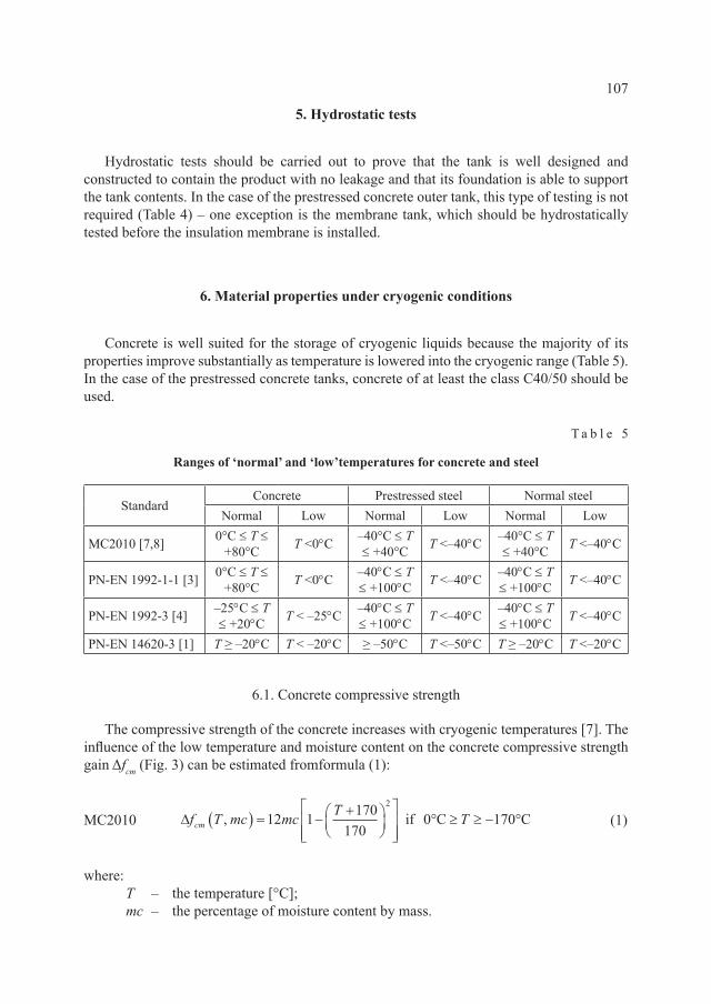
T a b l e 5
Ranges of ‘normal’ and ‘low’temperatures for concrete and steel
StandardConcrete Prestressed steel Normal steel
Normal Low Normal Low Normal Low
MC2010 [7,8] 0°C ≤ T ≤+80°C T <0°C –40°C ≤ T
≤ +40°C T <–40°C –40°C ≤ T ≤ +40°C T <–40°C
PN-EN 1992-1-1 [3] 0°C ≤ T ≤+80°C T <0°C –40°C ≤ T
≤ +100°C T <–40°C –40°C ≤ T ≤ +100°C T <–40°C
PN-EN 1992-3 [4] –25°C ≤ T ≤ +20°C T < –25°C –40°C ≤ T
≤ +100°C T <–40°C –40°C ≤ T ≤ +100°C T <–40°C
PN-EN 14620-3 [1] T ≥ –20°C T < –20°C ≥ –50°C T <–50°C T ≥ –20°C T <–20°C
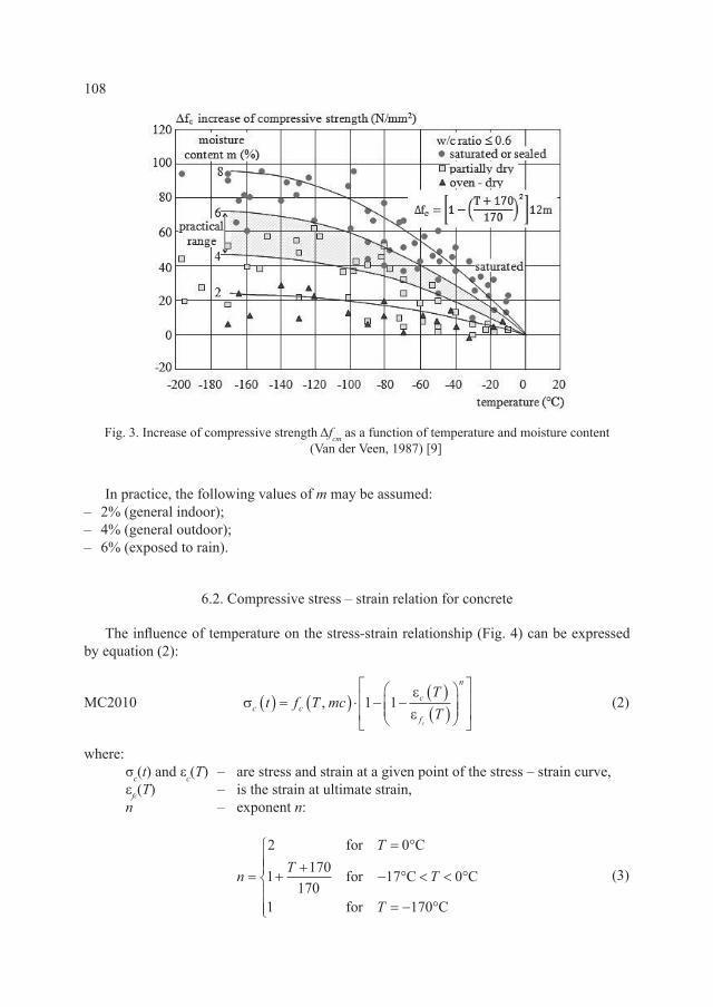
6.1. Concrete compressive strength
The compressive strength of the concrete increases with cryogenic temperatures [7]. The influence of the low temperature and moisture content on the concrete compressive strength gain Δfcm (Fig. 3) can be estimated fromformula (1):
MC2010 (1)
where: T – the temperature [°C]; mc – the percentage of moisture content by mass.
∆f T mc mc T Tcm ,( ) = −+
° ≥ ≥ − °12 1 170170
0 1702
if C C
108
In practice, the following values of m may be assumed: – 2% (general indoor); – 4% (general outdoor); – 6% (exposed to rain).
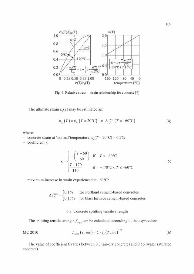
6.2. Compressive stress – strain relation for concrete
The influence of temperature on the stress-strain relationship (Fig. 4) can be expressed by equation (2):
MC2010 (2)
where: σc(t) and εc(T) – are stress and strain at a given point of the stress – strain curve, εfc(T) – is the strain at ultimate strain, n – exponent n:
(3)
Fig. 3. Increase of compressive strength Δfcm as a function of temperature and moisture content (Van der Veen, 1987) [9]
σεεc cc
f
n
t f T mcTT
c
( ) = ( ) ⋅ − −( )( )
, 1 1
n
TT T
T
=
= °
++
− ° < < °
= − °
2 0
1 170170
17 0
1 170
for C
for C C
for C
109
The ultimate strain εfc(T) may be estimated as:
(4)
where:– concrete strain at ‘normal’temperature: εfc(T = 20°C) = 0.2%– coefficient κ:
(5)
– maximum increase in strain experienced at –60°C:
6.3. Concrete splitting tensile strength
The splitting tensile strength fc,spli can be calculated according to the expression:
MC 2010 (6)
The value of coefficient Cvaries between 0.3 (air-dry concrete) and 0.56 (water saturated concrete).
Fig. 4. Relative stress – strain relationship for concrete [9]
ε ε κ εf f fc c cT T T( ) = = °( ) + ⋅ = − °( )20 60C Cmax∆
κ =−
+
> − °
+− ° < ≤ − °
1 6060
60
170110
170 60
T T
T T
if C
if C C
∆ε fcmax for Portland cement-based concretes
for blast=0 10 15. % . % ffurnace cement-based concretes
f T mc C f T mcc spli c,., ,( ) = ⋅ ( )0 67
110
A similar equation for tensile strength fctx is recommended in PN-EN 1992-3 [4]:
EC2-3 (7)
The values of coefficient α are shown in Table 6.
T a b l e 6
The coefficient α [4]
Tensile strength Water saturated concrete Dry concretefctm 0.47 0.30
fctk 0.05 0.27 0.21fctk 0.95 0.95 0.39
6.4. Concrete modulus of elasticity
The modulus of elasticity Ec increases with decreasing temperature.According to EC2-3 [4], the influence of the moisture content on the modulus of elasticity gain ΔEc can be estimated as:
EC2-3
For concrete exposed to temperature T = –165°C, the modulus of elasticity increases significantly [8]:
MC 2010
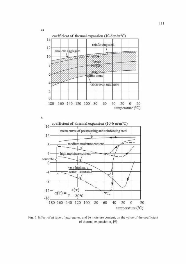
6.5. Coefficient of thermal expansion
The coefficient of thermal expansion αT decreases with reductions in temperature. The value of coefficient αT strongly depends on the content of free moisture in concrete (Fig. 5). In the case of water saturated concrete, expansion behaviour (negative value of coefficient αT) should be expected. For dry concrete, the coefficient of thermal expansion decreases by approximately 10% [8].
f fctx ckT= ⋅α 2 3/
∆E Tc = − °( ) ≈++
2528
CGPa for dry concreteGPa for water saturated concrrete
E TE TE Tc
c
c= − °( ) ≈× = °( )× = °( )165
1 15 201 5 20C
C for dry concreteC fo
.
. rr sealed concreteC for water saturated concrete1 8 20. × = °( )
E Tc
111
a)
b
Fig. 5. Effect of a) type of aggregates, and b) moisture content, on the value of the coefficient of thermal expansion αT [9]
112
6.6. Behaviour of normal and prestressed steel under cryogenic conditions
Generally, in the case of normal steel, the values of tensile strength, yield strength and the modulus of elasticity increase if the temperature decreases. The total elongation [in %] at maximum force increases initially but below –150°C, it decreases rapidly [10]. Tests on prestressing steel wires and strands showed that 0.1% proof stress and ultimate strength was higher than at room temperature and an elongation at maximum load was over 2% at temperature T = –196°C [11]. In both cases, normal and prestressing steel stress-strain diagrams are suitable for behaviour assessment at cryogenic temperature [8]. If the designed temperature is lower than –50°C, then the prestressing system (strands and anchorages) should be tested in assumed cryogenic conditions. A tensile test on notched and un-notched reinforcing steel bars should be conducted if the designed temperature is lower than –20°C [1.3].
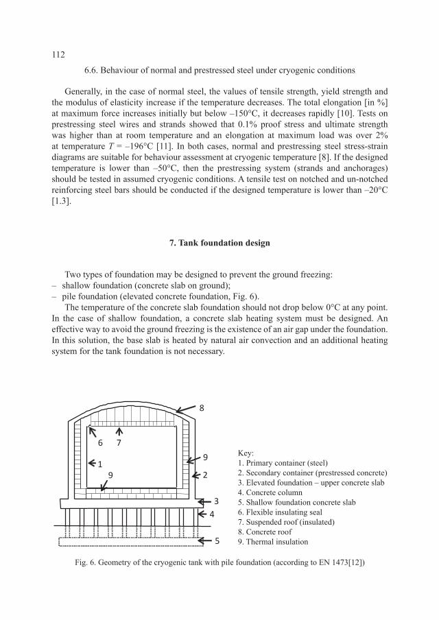
7. Tank foundation design
Two types of foundation may be designed to prevent the ground freezing:– shallow foundation (concrete slab on ground);– pile foundation (elevated concrete foundation, Fig. 6).
The temperature of the concrete slab foundation should not drop below 0°C at any point. In the case of shallow foundation, a concrete slab heating system must be designed. An effective way to avoid the ground freezing is the existence of an air gap under the foundation. In this solution, the base slab is heated by natural air convection and an additional heating system for the tank foundation is not necessary.
9
9
8
76
5
4
3
2
1
Key:1. Primary container (steel)2. Secondary container (prestressed concrete)3. Elevated foundation – upper concrete slab4. Concrete column5. Shallow foundation concrete slab6. Flexible insulating seal7. Suspended roof (insulated)8. Concrete roof9. Thermal insulation
Fig. 6. Geometry of the cryogenic tank with pile foundation (according to EN 1473[12])
113
8. Summary
This paper presented some general concepts of prestressed concrete containment tank constructions, load cases or combinations and material properties under cryogenic conditions according to EN 14620 and fib Model Code 2010. It concentrated on the main differences in the design aspects of concrete tanks in the case of ‘normal’ and ‘low’ temperature.
R e f e r e n c e s
[1] EN 14620:2010 Design and manufacture of site built, vertical, cylindrical, flat-bottomed steel tanks for the storage of refrigerated, liquefied gases with operating temperatures between 0°C and –165°C.
[1.1] Part 1: General; [1.2] Part 2: Metallic components; [1.3] Part 3: Concrete components; [1.4] Part 4: Insulation components; [1.5] Part 5: Testing, dryling, purging and cool-down;
[3] EN 1992-1-1:2008 Eurocode 2: Design of concrete structures – Part 1-1: General rules and rules for buildings .
[4] EN 1992-3:2008 Eurocode 2: Design of concrete structures – Part 3: Liquid retaining and containment structures.
[5] BS 777-3:1993 Flat-bottomed, vertical, cylindrical storage tanks for low temperature service.
Part 3: Recommendations for the design and construction of prestressed and reinforced concrete tanks and tank foundations, and for the design and installation of tank insulation, tank liners and tank coatings.
[6] EN 1991-4:2008 Eurocode 1 – Actions on structures – Part 4: Silos and tanks.[7] fib Model Code 2010, Bulletin 55, First complete draft – Volume 1, March 2010.[8] fib Model Code 2010, Bulletin 56, First complete draft – Volume 2, April 2010. [9] Van der Veen J.C., Properties of concrete at very low temperatures. A survey of the
literature, Report No. 25–87–2. Delft University of Technology, 1987.[10] FIP Special Report SR 88/2: Information on the behaviour at very low temperatures of
ribbed steels, June 1988.[11] FIP State of the Art Report: Cryogenic behaviour of materials for prestressing concrete,
1982.[12] EN 1473:2007 Installation and equipment for liquefied natural gas –Design of onshore
installations.