Rozproszone Systemy Automatyki Wyk ad 10 - diablo.iiar.pwr ...
42
DCS Rozproszone Systemy Automatyki Wyklad 10 Adam Ratajczak Pracownia Automatyki, Modelowania i Mechatroniki Katedra Automatyki, Mechatroniki i Systemów Sterowania Wydzial Elektroniki Politechnika Wroclawska Copyright c 2021 Adam Ratajczak 1 1 Niniejszy dokument zawiera materialy do wykladu z przedmiotu Rozproszone Systemy Automatyki. Jest on udostępniony pod warunkiem wykorzystania wylącznie do wlasnych, prywatnych potrzeb i może być kopiowany wylącznie w calości, razem ze stroną tytulową.
Transcript of Rozproszone Systemy Automatyki Wyk ad 10 - diablo.iiar.pwr ...
DCSRozproszone Systemy Automatyki
Wykład 10
Adam Ratajczak
Pracownia Automatyki, Modelowania i MechatronikiKatedra Automatyki, Mechatroniki i Systemów Sterowania
Wydział ElektronikiPolitechnika Wrocławska
Copyright c© 2021 Adam Ratajczak1
1Niniejszy dokument zawiera materiały do wykładu z przedmiotu Rozproszone Systemy Automatyki.Jest on udostępniony pod warunkiem wykorzystania wyłącznie do własnych, prywatnych potrzeb i możebyć kopiowany wyłącznie w całości, razem ze stroną tytułową.
Wstęp Niezawodność Dostępność Redundancja
Definicje wstępne
RedundancjaRedundancja to urządzenia i fragmenty kodu, które byłyby zbędnegdyby system działał bezbłędnie. Redundancję stosuje się dozwiększenia niezawodności i dostępności systemów automatyki.
Adam Ratajczak DCS – Wykład 10 1 / 37
Wstęp Niezawodność Dostępność Redundancja
Definicje wstępne
Fault–tolerant – odporność na awarieOdporność na awarie to zdolność systemu do przeprowadzeniaprawidłowego działania niezależnie od problemów sprzętowychi błędów w programie.
Adam Ratajczak DCS – Wykład 10 2 / 37
Wstęp Niezawodność Dostępność Redundancja
Definicje wstępne
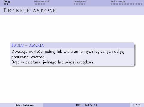
Fault – awariaDewiacja wartości jednej lub wielu zmiennych logicznych od jejpoprawnej wartości.Błąd w działaniu jednego lub więcej urządzeń.
Adam Ratajczak DCS – Wykład 10 3 / 37
Wstęp Niezawodność Dostępność Redundancja
Definicje
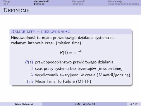
Reliability – niezawodnośćNiezawodność to miara prawidłowego działania systemu nazadanym interwale czasu (mission time).
R(t) = e−λt
R(t) prawdopodobieństwo prawidłowego działaniat czas pracy systemu bez przestojów (mission time)λ współczynnik awaryjności w czasie (N awarii/godzinę)
1/λ Mean Time To Failure (MTTF)
Adam Ratajczak DCS – Wykład 10 4 / 37
Wstęp Niezawodność Dostępność Redundancja
Reliability
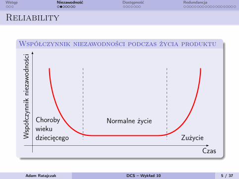
Współczynnik niezawodności podczas życia produktu
Czas
Współczynnikniezaw
odno
ści
Chorobywiekudziecięcego
Normalne życie
Zużycie
Adam Ratajczak DCS – Wykład 10 5 / 37
Wstęp Niezawodność Dostępność Redundancja
Reliability
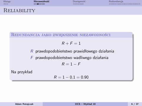
Redundancja jako zwiększenie niezawodności
R + F = 1
R prawdopodobieństwo prawidłowego działaniaF prawdopodobieństwo wadliwego działania
R = 1− F
Na przykładR = 1− 0.1 = 0.90
Adam Ratajczak DCS – Wykład 10 6 / 37
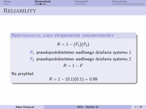
Wstęp Niezawodność Dostępność Redundancja
Reliability
Redundancja jako zwiększenie niezawodności
R = 1− (F1)(F2)
F1 prawdopodobieństwo wadliwego działania systemu 1F2 prawdopodobieństwo wadliwego działania systemu 2
R = 1− F
Na przykładR = 1− (0.1)(0.1) = 0.99
Adam Ratajczak DCS – Wykład 10 7 / 37
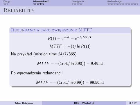
Wstęp Niezawodność Dostępność Redundancja
Reliability
Redundancja jako zwiększenie MTTF
R(t) = e−λt = e−t/MTTF
MTTF = −(t/ lnR(t))
Na przykład (mission time 24/7/365)
MTTF = −(1rok/ ln 0.90)) = 9.49lat
Po wprowadzeniu redundancji
MTTF = −(1rok/ ln 0.99)) = 99.50lat
Adam Ratajczak DCS – Wykład 10 8 / 37
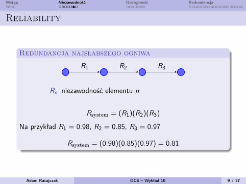
Wstęp Niezawodność Dostępność Redundancja
Reliability
Redundancja najsłabszego ogniwa
R1 R2 R3
Rn niezawodność elementu n
Rsystem = (R1)(R2)(R3)
Na przykład R1 = 0.98, R2 = 0.85, R3 = 0.97
Rsystem = (0.98)(0.85)(0.97) = 0.81
Adam Ratajczak DCS – Wykład 10 9 / 37
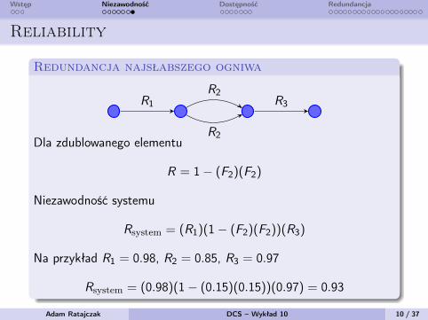
Wstęp Niezawodność Dostępność Redundancja
Reliability
Redundancja najsłabszego ogniwa
R1
R2
R2R3
Dla zdublowanego elementu
R = 1− (F2)(F2)
Niezawodność systemu
Rsystem = (R1)(1− (F2)(F2))(R3)
Na przykład R1 = 0.98, R2 = 0.85, R3 = 0.97
Rsystem = (0.98)(1− (0.15)(0.15))(0.97) = 0.93
Adam Ratajczak DCS – Wykład 10 10 / 37
Wstęp Niezawodność Dostępność Redundancja
Definicje
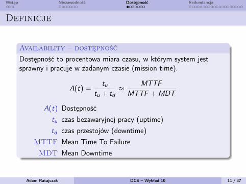
Availability – dostępność
Dostępność to procentowa miara czasu, w którym system jestsprawny i pracuje w zadanym czasie (mission time).
A(t) =tu
tu + td≈ MTTF
MTTF +MDT
A(t) Dostępnośćtu czas bezawaryjnej pracy (uptime)td czas przestojów (downtime)
MTTF Mean Time To FailureMDT Mean Downtime
Adam Ratajczak DCS – Wykład 10 11 / 37
Wstęp Niezawodność Dostępność Redundancja
Availability
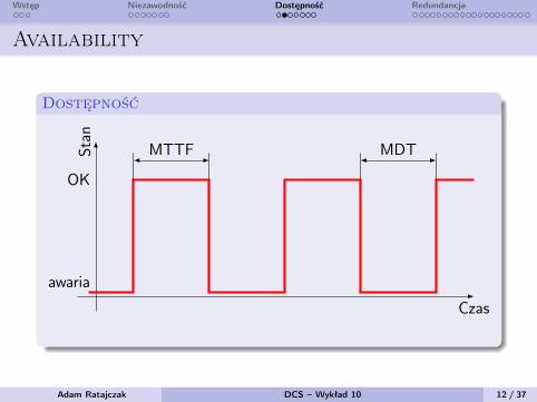
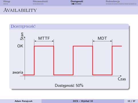
Dostępność
Czas
Stan
awaria
OK
MTTF MDT
Dostępność 50%
Adam Ratajczak DCS – Wykład 10 12 / 37
Wstęp Niezawodność Dostępność Redundancja
Availability
Dostępność
Czas
Stan
awaria
OK
MTTF MDT
Dostępność 50%
Adam Ratajczak DCS – Wykład 10 12 / 37
Wstęp Niezawodność Dostępność Redundancja
Availability
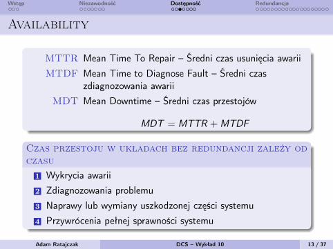
MTTR Mean Time To Repair – Średni czas usunięcia awariiMTDF Mean Time to Diagnose Fault – Średni czas
zdiagnozowania awariiMDT Mean Downtime – Średni czas przestojów
MDT = MTTR +MTDF
Czas przestoju w układach bez redundancji zależy odczasu
1 Wykrycia awarii2 Zdiagnozowania problemu3 Naprawy lub wymiany uszkodzonej części systemu4 Przywrócenia pełnej sprawności systemu
Adam Ratajczak DCS – Wykład 10 13 / 37
Wstęp Niezawodność Dostępność Redundancja
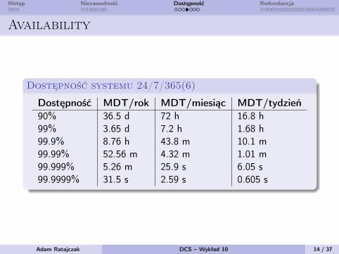
Availability
Dostępność systemu 24/7/365(6)
Dostępność MDT/rok MDT/miesiąc MDT/tydzień90% 36.5 d 72 h 16.8 h99% 3.65 d 7.2 h 1.68 h99.9% 8.76 h 43.8 m 10.1 m99.99% 52.56 m 4.32 m 1.01 m99.999% 5.26 m 25.9 s 6.05 s99.9999% 31.5 s 2.59 s 0.605 s
Adam Ratajczak DCS – Wykład 10 14 / 37

Wstęp Niezawodność Dostępność Redundancja
Definicje
Maintainability - konserwacyjność, obsługiwalność
Zdolność systemu do zmian konfiguracyjnych i szybkościprzeprowadzania napraw.
Czynniki wpływające na maintainability
Diagnostyka do wykrywania i izolowania awariiZgłaszanie awariiNarzędzia do rozwiązywania awariiPrzeszkolenie personeluPrzystepność systemuCzas wymiany/naprawyMożliwość dodawania i zmiany komponentów
Adam Ratajczak DCS – Wykład 10 15 / 37

Wstęp Niezawodność Dostępność Redundancja
Maintainability
Technologie poprawiające maintainability
Dodawanie i usuwanie modułów pod zasilaniemDodawanie on-line węzłów I/OEdycja programu on-line i ładowanie programu on-lineWbudowane przełączanie pomiędzyproducentem/konsumentem w komunikacjachWewnętrzne mechanizmy diagnostyczneDiagnostyka problemów obwodów obiektowych: zwarcie,przerwa w obwodzie, itp.Konfigurowalna reakcja na awarię: hold last state, turn offDiagnostyka czujników i aktuatorów poprzez technologiefieldbus’oweDodawanie obiektów (I/O, tags, HMI) podczas pracy
Adam Ratajczak DCS – Wykład 10 16 / 37
Wstęp Niezawodność Dostępność Redundancja
Availability
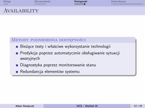
Metody podniesienia dostępności
Bieżące testy i właściwe wykorzystanie technologiiPredykcja poprzez automatycznie obsługiwanie sytuacjiawaryjnychDiagnostyka poprzez monitorowanie stanuRedundancja elementów systemu
Adam Ratajczak DCS – Wykład 10 17 / 37
Wstęp Niezawodność Dostępność Redundancja
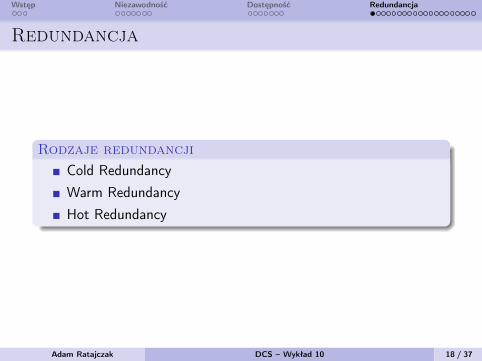
Redundancja
Rodzaje redundancjiCold RedundancyWarm RedundancyHot Redundancy
Adam Ratajczak DCS – Wykład 10 18 / 37
Wstęp Niezawodność Dostępność Redundancja
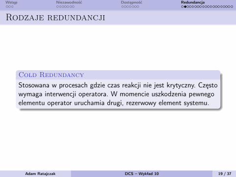
Rodzaje redundancji
Cold RedundancyStosowana w procesach gdzie czas reakcji nie jest krytyczny. Częstowymaga interwencji operatora. W momencie uszkodzenia pewnegoelementu operator uruchamia drugi, rezerwowy element systemu.
Adam Ratajczak DCS – Wykład 10 19 / 37

Wstęp Niezawodność Dostępność Redundancja
Rodzaje redundancji
Warm RedundancyStosowane w procesach gdzie czas reakcji jest istotny ale możewystąpić krótkotrwały przestój. Typowo, w skład wchodzą dwakontrolery (primary i standby). Primary przetwarza I/O, a secondaryoczekuje na problemy sterownikia primary. Dane pomiędzysterownikami są przekazywane cyklicznie. Po przełączeniu sterownikstandby może wymagać kilku cykli aby odbudować brakujące danei przejąć całkowitą kontrolę nad procesem.
Adam Ratajczak DCS – Wykład 10 20 / 37
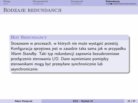
Wstęp Niezawodność Dostępność Redundancja
Rodzaje redundancji
Hot RedundancyStosowane w procesach, w których nie może wystąpić przestój.Konfiguracja sprzętowa jest w zasadzie taka sama jak w przypadkuWarm Standby. Taki typ redundancji zapewnia bezuderzenioweprzełączenie sterowania I/O. Dane wymieniane pomiędzysterownikami mogą być przesyłane synchronicznie lubasynchronicznie.
Adam Ratajczak DCS – Wykład 10 21 / 37
Wstęp Niezawodność Dostępność Redundancja
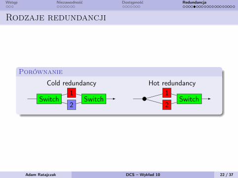
Rodzaje redundancji
Porównanie
Cold redundancy Hot redundancy
Switch Switch1
2Switch
1
2
Adam Ratajczak DCS – Wykład 10 22 / 37
Wstęp Niezawodność Dostępność Redundancja
Redundancja
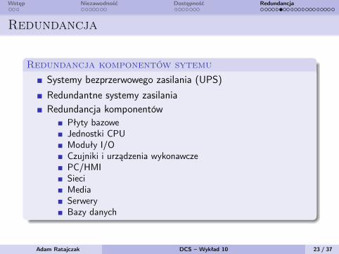
Redundancja komponentów sytemuSystemy bezprzerwowego zasilania (UPS)Redundantne systemy zasilaniaRedundancja komponentów
Płyty bazoweJednostki CPUModuły I/OCzujniki i urządzenia wykonawczePC/HMISieciMediaSerweryBazy danych
Adam Ratajczak DCS – Wykład 10 23 / 37

Wstęp Niezawodność Dostępność Redundancja
Redundancja
Przyczyny przełączeń active–stand-by1 Awaria sprzętu2 Błąd połączenia pomiędzy aktywnym sterownikiem a wyspami
I/O3 Wypięcie modułu z płyty bazowej4 Ręczne wymuszenie przełączenia5 Instrukcja w programie6 Utrata zasilania7 Błąd pamięci aktywnej jednostki8 Błąd w programie (watchdog)
Adam Ratajczak DCS – Wykład 10 24 / 37
Wstęp Niezawodność Dostępność Redundancja
Redundancja
Redundancja modułowa
DMR TMR
Voter1
2Voter
123
QMR
Voter
1
2
3
4
Adam Ratajczak DCS – Wykład 10 25 / 37
Wstęp Niezawodność Dostępność Redundancja
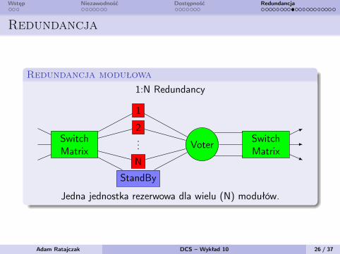
Redundancja
Redundancja modułowa1:N Redundancy
SwitchMatrix
Voter SwitchMatrix
1
2...
N
StandBy
Jedna jednostka rezerwowa dla wielu (N) modułów.
Adam Ratajczak DCS – Wykład 10 26 / 37
Wstęp Niezawodność Dostępność Redundancja
Redundancja
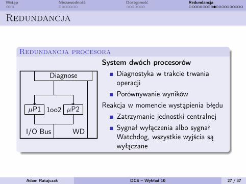
Redundancja procesora
WDI/O Bus
µP1 µP21oo2
Diagnose
System dwóch procesorówDiagnostyka w trakcie trwaniaoperacjiPorównywanie wyników
Reakcja w momencie wystąpienia błęduZatrzymanie jednostki centralnejSygnał wyłączenia albo sygnałWatchdog, wszystkie wyjścia sąwyłączane
Adam Ratajczak DCS – Wykład 10 27 / 37
Wstęp Niezawodność Dostępność Redundancja
Redundancja
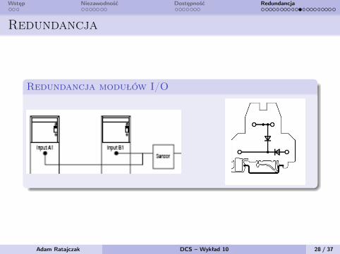
Redundancja modułów I/O
Adam Ratajczak DCS – Wykład 10 28 / 37
Wstęp Niezawodność Dostępność Redundancja
Redundancja
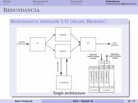
Redundancja modułów I/O (Allen–Bradley)
Rockwell Automation Publication 1715-UM001F-EN-P - July 2017 23
Redundancy System Overview Chapter 1
Simplex Architecture
Simplex I/O modules fail-safe on the first detected module fault. The process under control shuts down when the fault is detected.
This configuration is suitable for high and low demand module applications.
Figure 5 - Simplex Architecture - Input and Output
IO B
ASE
1715
-A31
0
CH1
CH1
CH1
CH1
CH1
CH1
CH1
CH1
TERMINAL IDENTITY
AOTADual.
CH1
CH1
CH1
CH1
CH1
CH1
CH1
CH1
TERMINAL IDENTITY
AOTADual.
CH1
CH1
CH1
CH1
CH1
CH1
CH1
CH1
TERMINAL IDENTITY
AOTADual.
1715
-AEN
TR
1715
-AEN
TR
1715
-IB16
D
1715
-OB8
DE
ADAPTER
ADAPTER
O/PI/PSENSORS
FINAL ELEMENTS
1715-TADOB8DE
1715-TADIB16D
1715-A2A 1715-A3IO
ControlLogix
CIP
NET
WO
RK
Digital Output Simplex Termination
Assembly
Digital Input Simplex Termination
Assembly
Adapter Base Unit
I/O Base Units
45241
Single architecture
Adam Ratajczak DCS – Wykład 10 29 / 37
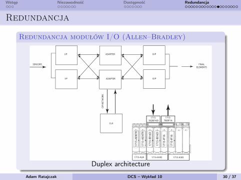
Wstęp Niezawodność Dostępność Redundancja
Redundancja
Redundancja modułów I/O (Allen–Bradley)
Rockwell Automation Publication 1715-UM001F-EN-P - July 2017 25
Redundancy System Overview Chapter 1
Figure 7 - Duplex Architecture Inputs and Outputs
Termination assemblies can span across I/O base units.
1715
-AEN
TR
1715
-AEN
TR
ADAPTER
ADAPTER
O/PI/P
SENSORS FINAL ELEMENTS
IO B
ASE
1715
-A31
0
CH1
CH1
CH1
CH1
CH1
CH1
CH1
CH1
TERMINAL IDENTITY
AOTADual.
CH1
CH1
CH1
CH1
CH1
CH1
CH1
CH1
TERMINAL IDENTITY
AOTADual.
CH1
CH1
CH1
CH1
CH1
CH1
CH1
CH1
TERMINAL IDENTITY
AOTADual.
1715
-IB16
D
171
5-IF
16
I/P O/P
IO B
ASE
1715
-A31
0
CH1
CH1
CH1
CH1
CH1
CH1
CH1
CH1
TERMINAL IDENTITY
AOTADual.
CH1
CH1
CH1
CH1
CH1
CH1
CH1
CH1
TERMINAL IDENTITY
AOTADual.
CH1
CH1
CH1
CH1
CH1
CH1
CH1
CH1
TERMINAL IDENTITY
AOTADual.
1715
-IB16
D
171
5-IF
16
1715-TADIF16
1715-TADIB16D
1715-A2A 1715-A3IO 1715-A3IO
CLX
CIP
NET
WO
RK
Duplex architecture
Adam Ratajczak DCS – Wykład 10 30 / 37
Wstęp Niezawodność Dostępność Redundancja
Redundancja
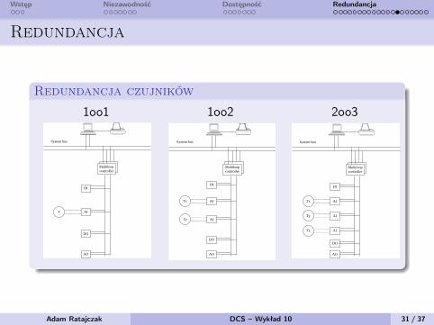
Redundancja czujników
1oo1 1oo2 2oo3
1.10 Redundant and Voting Systems
129
FIELD INSTRUMENT REDUNDANCY AND VOTING
The above concepts apply not only to process computers butalso to basic process control systems (BPCSs) and safety instru-mented systems (SISs), where they also improve performance,availability, and reliability. In the case of field instrumentsand final control elements, they mainly guarantee continuity ofoperation and increase uptime, whereas, in SIS systems, theyminimize nuisance or spurious interventions and alarms.
The techniques used in BPCS and SIS systems are similarand have initially been developed for the inherently moredemanding SIS applications. For SIS systems, the need ofinternational regulations has been recognized (ANSI/ISA-84.01-1996,
18
IEC 61508-1998/2000,
19
and IEC 61511,
20
indraft version) while, for non-safety related control loops, thisis left to good engineering practice. Therefore, the discussionof redundancy and voting techniques, as applied to the fieldinstruments of BPCS systems, will be based on the SISstandards as guidelines. The BPCS goal is to improve controlloop availability such that the trigger point for the interven-tion of the associated SIS system is unlikely ever to bereached. Thereby, redundancy in BPCS also improves safety.This is because increased availability reduces the number ofshutdowns, which tend to shorten the life of the plant due tothe resulting thermal and other stresses.
One of the main objectives of measurement and controlspecialists is to improve the availability and accuracy ofmeasurements. To achieve that goal and to minimize system-atic uncertainty while increasing reliability, correct specifi-cation, instrument selection, and installation are essential.
Assuming that the transmitters have been properly spec-ified, selected, and installed, one can further improve totalperformance by measuring the same variable with more thanone sensor. Depending on the importance of the measurement,redundancy can involve two or more detectors measuring thesame process variable. When three or more sensors are used,one can select the “majority view” by voting. With thisapproach, one would select
m
measurements out of the total
n
number of signals so, that
m
>
n
/2. In industrial practice,
n
is normally 3 so that
m
is 2. The redundant and voting techniques have been standard-
ized in various SIS-related documents, including ANSI/ISA-84.01, IEC 61508, and IEC 61511. The SIS systems usuallyevaluate on–off signals or threshold limits of analog signalswhereas, in process control, redundancy and voting is obtainedby the evaluation of multiple analog signals. The main differ-ence between BPCS and SIS systems is that SIS is a “dormant”system, but continuously self-checking, and it is called uponto operate only in an emergency. In addition, the SIS is failsafe; i.e., if it fails, it brings the plant to a safe status. SISmalfunctioning is inferred from diagnostic programs and notfrom plant conditions, because the plant cannot be shut downor brought to unsafe conditions just to test the SIS system. Allinternational regulations follow this approach.
In contrast to SIS systems, the BPCS control loops arealways active and, if they malfunction, they actuate alarms,
which the operator immediately notices. The consequence isthat the SIS-based definitions developed in IEC 61508, tosome extent, can also be used as guidelines for control loopsthat require high uptime and whose unavailability would,within a short time, drive the plant to conditions requiringplant shutdown.
IEC 61508 Part 6 gives the definition of the variousarchitectures most commonly used in the safety instrumentedsystems. They apply for use with one, two, or three elementsand their various combinations. The elements that are usedin a single or multiple configuration can be either transmittersor final control elements, but they are mainly for transmitters,and only very rarely for control valves, because of the sub-stantial difference in costs. The control system, such as aDCS system, is usually configured with multiple controllersand redundant other system components (e.g., system bus,I/O bus, HMI). IEC 61508 considers and gives definitions tothe configurations described below.
Single-Transmitter Configuration (Figure 1.10b)
1oo1 A single transmitter is used, as in many controlloops. These loops consist of an analog transmitterand an analog controller (pneumatic or electronic).This configuration is the most prone to overall mal-functioning. Errors and failures can be caused by asticking control valve or transmitter or by an out ofrange signal (up or down scale). In these loops,
FIG. 1.10b
1oo1/1oo1D transmitter input.
Multiloopcontroller
DI
AI
DO
AO
System bus
T
© 2003 by Béla Lipták
130
General Considerations
diagnostic protection is very limited. Remember, inthe past, the burn-out feature of thermocouples wasalmost the only diagnostic function implemented inthe mV/psi converters or mV/mA transducers.
1oo1D A single transmitter is used, with diagnos-tic coverage integral to the transmitter (e.g., self-validating transmitters
21,22
) and/or external in thecontrol system.
Two-Transmitter Configuration (Figure 1.10c)
1oo2 Two transmitters in parallel are used; the failureof one determines the loss of control. In principle,this definition cannot be borrowed from IEC 61508.
1oo2D Two transmitters in parallel are used, withdiagnostic coverage mainly residing in the controlsystem. The type of diagnostic functions will becovered afterward.
2oo2 Two transmitters in parallel are used. The lossof control should be determined by the failure ofboth. In principle, this definition cannot be borrowedfrom IEC 61508.
Three-Transmitter Configuration (Figure 1.10d)
2oo3 Three transmitters in parallel are used. The con-current value indicated by two of them is assumed
as correct and representative of the process condi-tions. Concurrency means that they differ by nomore than X%.
Diagnostic Coverage
The diagnostic coverage in the BPCS is much less than inthe SIS, for reasons outlined previously, and is providedmainly in and by the DCS, which has the capability of com-paring the signals received from the transmitters and deter-mining whether they are within the imposed limits so as toconsider them to be concurrent. If an inconsistency isdetected, the DCS is capable of signaling the abnormal sit-uation and to maintain control, at least in some instances,without operator intervention.
1oo1D The diagnostic coverage can be partly integralto the transmitter and/or external in the controlsystem (rate of change alarms, overrange alarmsdetecting the individual fault). In a broader sense,in addition, the material balance (data reconcilia-tion) performed in the DCS can contribute to detecta failure in the flow transmitters or their unreliablereading.
1oo2D The signal from each transmitter is checked toverify if it is within the validity limits (i.e., 4-20 mA).If a transmitter is outside the validity range, its signal
FIG. 1.10c
2oo2D transmitter input.
AO
DI
DO
AI
AI
Tx
Ty
Multiloopcontroller
System bus
FIG. 1.10d
2oo3 transmitter input.
AO
DI
DO
AI
AITz
Tx
AITy
Multiloopcontroller
System bus
© 2003 by Béla Lipták
Adam Ratajczak DCS – Wykład 10 31 / 37
Wstęp Niezawodność Dostępność Redundancja
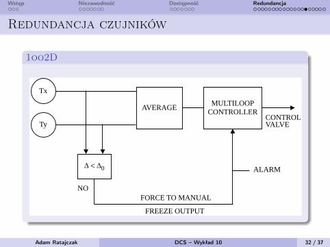
Redundancja czujników
1oo2D
1.10 Redundant and Voting Systems
131
is discarded, the controller receives the value fromthe other transmitter and an alarm is issued to warnthe operator about the malfunctioning. If both trans-mitters are within validity limits, the differenceamong their signals is calculated. In case the differ-ence is within a preset value (in the range of fewpercent), the average value is assumed as good andused for the control function (Figure 1.10e).
The acceptable discrepancy between the twotransmitters depends on the measurement condi-tions; for instance, the acceptable discrepancy in thelevel measurement in a steam drum is larger than inthe case of a pressure measurement. As an indica-tion, for two level transmitters installed at differentends of the steam drum, 5% discrepancy is accept-able. However, for pressure measurement, 2%should not be exceeded. Normally, in the processindustry, it is not necessary to select a very smalldiscrepancy (such as twice the declared accuracy)between the transmitted values, because the differ-ence could be the result of many causes other thana transmitter failure or the need for recalibration (themain reason could be the installation). Sometimes,
a common percentage discrepancy value is chosenand used for all measures, because experience hasshown that it is unlikely that a transmitter fails to avalue close to the correct one.
When the discrepancy is beyond the preset value,but both signals are within validity limits, it is notpossible to determine which one is invalid. In thiscase, an alarm is produced, and the controller isautomatically forced to manual, with output frozenat the last valid value. The operator then has theresponsibility to discard one of the two transmittersand use the other as the input to the controller, thenswitch to auto again.
2oo3 The signal from each transmitter is checked toverify whether it is within the validity limits (i.e., 4to 20 mA). If a transmitter is outside the validityrange, its signal is discarded as invalid, and theremaining two are used as if they were in 1oo2Dconfiguration. If no invalid signal is detected, thenthe discrepancy between the values is calculated.Supposing the three signals are X, Y, and Z, thedifferences X
−
Y, Y
−
Z, and Z
−
X are calculated.If each of them is within the preset limits, themedian value is taken as good and used as processvariable by the controller. If one difference exceedsthe preset limit, an alarm is issued to the operator,and the median value is used as process variable forthe controller. If two differences exceed the presetlimit, the value of the transmitter involved in boththe excessive differences is discarded, an alarm isissued to the operator, and the average value of theremaining two is used as process value. If all threedifferences exceed the preset limit, this means thatat least two transmitters are not reliable. In this case,the controller is automatically forced to manual,with output equal to last valid value (Figure 1.10f).
FIG. 1.10e
1oo2D signal conditioning.
Tx
Ty
∆ < ∆0
AVERAGEMULTILOOP
CONTROLLERCONTROLVALVE
NOFORCE TO MANUAL
FREEZE OUTPUT
ALARM
FIG. 1.10f
2oo3 signal conditioning.
Tx
Ty
∆ < ∆0 ∆ < ∆0 ∆ < ∆0
COMPUTING
MODULE
MULTILOOPCONTROLLER
CONTROLVALVE
Tz
A B C
ALARM
TRUTH TABLE
A YES YES YES NOB YES YES NO NOC YES NO NO NOComputing Module Median Median Average NONEAlarm NO YES YES YESDiscard NONE NONE Tz Tx, Ty, TzForce contr. output to man. NO NO NO YES
© 2003 by Béla Lipták
Adam Ratajczak DCS – Wykład 10 32 / 37
Wstęp Niezawodność Dostępność Redundancja
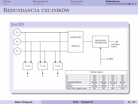
Redundancja czujników
2oo3D
1.10 Redundant and Voting Systems
131
is discarded, the controller receives the value fromthe other transmitter and an alarm is issued to warnthe operator about the malfunctioning. If both trans-mitters are within validity limits, the differenceamong their signals is calculated. In case the differ-ence is within a preset value (in the range of fewpercent), the average value is assumed as good andused for the control function (Figure 1.10e).
The acceptable discrepancy between the twotransmitters depends on the measurement condi-tions; for instance, the acceptable discrepancy in thelevel measurement in a steam drum is larger than inthe case of a pressure measurement. As an indica-tion, for two level transmitters installed at differentends of the steam drum, 5% discrepancy is accept-able. However, for pressure measurement, 2%should not be exceeded. Normally, in the processindustry, it is not necessary to select a very smalldiscrepancy (such as twice the declared accuracy)between the transmitted values, because the differ-ence could be the result of many causes other thana transmitter failure or the need for recalibration (themain reason could be the installation). Sometimes,
a common percentage discrepancy value is chosenand used for all measures, because experience hasshown that it is unlikely that a transmitter fails to avalue close to the correct one.
When the discrepancy is beyond the preset value,but both signals are within validity limits, it is notpossible to determine which one is invalid. In thiscase, an alarm is produced, and the controller isautomatically forced to manual, with output frozenat the last valid value. The operator then has theresponsibility to discard one of the two transmittersand use the other as the input to the controller, thenswitch to auto again.
2oo3 The signal from each transmitter is checked toverify whether it is within the validity limits (i.e., 4to 20 mA). If a transmitter is outside the validityrange, its signal is discarded as invalid, and theremaining two are used as if they were in 1oo2Dconfiguration. If no invalid signal is detected, thenthe discrepancy between the values is calculated.Supposing the three signals are X, Y, and Z, thedifferences X
−
Y, Y
−
Z, and Z
−
X are calculated.If each of them is within the preset limits, themedian value is taken as good and used as processvariable by the controller. If one difference exceedsthe preset limit, an alarm is issued to the operator,and the median value is used as process variable forthe controller. If two differences exceed the presetlimit, the value of the transmitter involved in boththe excessive differences is discarded, an alarm isissued to the operator, and the average value of theremaining two is used as process value. If all threedifferences exceed the preset limit, this means thatat least two transmitters are not reliable. In this case,the controller is automatically forced to manual,with output equal to last valid value (Figure 1.10f).
FIG. 1.10e
1oo2D signal conditioning.
Tx
Ty
∆ < ∆0
AVERAGEMULTILOOP
CONTROLLERCONTROLVALVE
NOFORCE TO MANUAL
FREEZE OUTPUT
ALARM
FIG. 1.10f
2oo3 signal conditioning.
Tx
Ty
∆ < ∆0 ∆ < ∆0 ∆ < ∆0
COMPUTING
MODULE
MULTILOOPCONTROLLER
CONTROLVALVE
Tz
A B C
ALARM
TRUTH TABLE
A YES YES YES NOB YES YES NO NOC YES NO NO NOComputing Module Median Median Average NONEAlarm NO YES YES YESDiscard NONE NONE Tz Tx, Ty, TzForce contr. output to man. NO NO NO YES
© 2003 by Béla Lipták
Adam Ratajczak DCS – Wykład 10 33 / 37
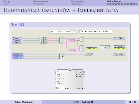
Wstęp Niezawodność Dostępność Redundancja
Redundancja czulników – Implementacja
2oo3D
Adam Ratajczak DCS – Wykład 10 34 / 37
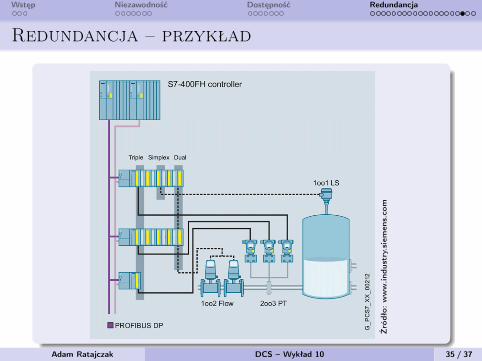
Wstęp Niezawodność Dostępność Redundancja
Redundancja – przykład
Źró
dło:
ww
w.in
dust
ry.sie
men
s.co
m
Adam Ratajczak DCS – Wykład 10 35 / 37
Wstęp Niezawodność Dostępność Redundancja
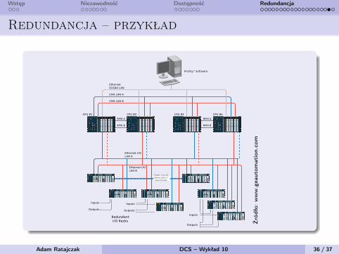
Redundancja – przykład
3
GE Intelligent Platforms believes a quad redundancy control system provides superior reliability and availability for the most demanding industrial and commercial applications— ensuring the most seamless redundant control switchover. Its revolutionary Quad PAC system ensures business con-tinuity by providing uninterrupted control of applications and processes in the event of individual system component failures. The next section explains the technical details of GE Intelligent Platforms’ Quad PAC system.
The Quad PAC solution architecture
The Quad PAC application consists of two redundant pairs of GE Intelligent Platforms’ PACSystems* RX7i controllers working in unison, for a total of four RX7i controllers and their associated items (racks, power supplies, etc). The controllers in the pairs are connected via redundant high-speed fiber optic modules, which provide synchronized logic solving and data transfer between the controllers. Similar technology is used via network hubs to tie all four controllers into a cohesive quad-redundant solution.
GE Intelligent Platforms’ unique Quad PAC redundant control system provides two mirror-imaged pairs of redundant controllers, whereby one of the four controllers can back up any of the other controllers in the system.
CMX LAN A
CMX LAN B
RMX A
CPU #1 CPU #4CPU #3CPU #2
RMX B
Ethernet I/OLAN A
RedundantI/O Racks
Ethernet I/OLAN B
Inputs
Outputs
Inputs
Outputs
Inputs
Outputs
RMX A
RMX B
From 1 to 26Generators /
Auxiliaries
EthernetSCADA LAN
Proficy* Software
Źró
dło:
ww
w.g
eaut
omat
ion.
com
Adam Ratajczak DCS – Wykład 10 36 / 37
Wstęp Niezawodność Dostępność Redundancja
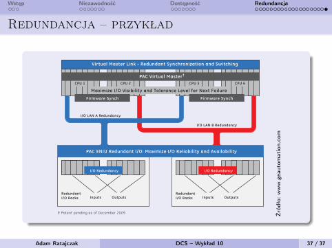
Redundancja – przykład
5
The redundant fiber-optic PAC Virtual Master LINK provides both high-speed process data synchronization and role switching of the Quad Master Controller. The instantaneous sharing of process and I/O data to each of the controllers allows any one of the controllers to take on mastership of the process at any time.
The PAC ENIU redundant I/O networking infrastructure links all the Quad PAC controllers, generators and/or auxiliary PACSystems RX3i controllers, and all remote I/O drops. The unique, multi-path application of the Ethernet networking
infrastructure provides the Quad PAC controllers with both constant and maximum visibility of the field I/O data, thereby maximizing overall system reliability and availability.
The network infrastructure provides scalability with indus-trially hardened, standards-based Ethernet network components, enabling the infrastructure to leverage newer or higher performing technologies as Ethernet standards advance. For example, users can factor in considerations such as migrating to future 10 Gbit fiber-based Ethernet backbones or using media redundancy with “Ring” topologies.
Functional Block Diagram
Predictive intelligence schemaIn the Quad PAC architecture, if the Master Controller fails, the system continually provides a real-time calculation of the system at any point in time to identify the backup controller that has the best “look-ahead view” of the entire control and remote I/O system components to take over mastership of the system—ensuring maximized uptime.
Firmware Synch Firmware Synch
Virtual Master Link - Redundant Synchronization and Switching
PAC ENIU Redundant I/O: Maximize I/O Reliability and Availability
I/O LAN A Redundancy
I/O LAN B Redundancy
I/O Redundancy I/O Redundancy
Redundant I/O Racks
Redundant I/O RacksInputs Outputs Inputs Outputs
Maximize I/O Visibility and Tolerance Level for Next Failure
CPU 1 CPU 4CPU 3CPU 2
PAC Virtual Master†
† Patent pending as of December 2009 Źró
dło:
ww
w.g
eaut
omat
ion.
com
Adam Ratajczak DCS – Wykład 10 37 / 37
Słowniczek
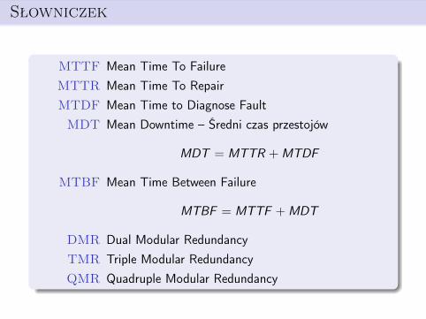
MTTF Mean Time To FailureMTTR Mean Time To RepairMTDF Mean Time to Diagnose FaultMDT Mean Downtime – Średni czas przestojów
MDT = MTTR +MTDF
MTBF Mean Time Between Failure
MTBF = MTTF +MDT
DMR Dual Modular RedundancyTMR Triple Modular RedundancyQMR Quadruple Modular Redundancy
Słowniczek
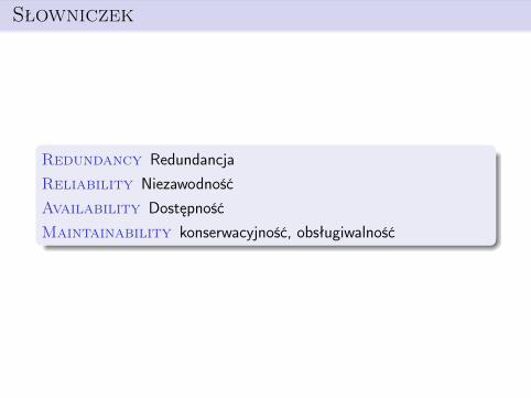
Redundancy RedundancjaReliability NiezawodnośćAvailability DostępnośćMaintainability konserwacyjność, obsługiwalność
Literatura
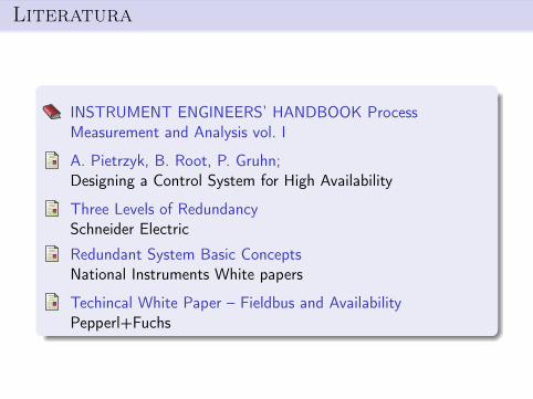
INSTRUMENT ENGINEERS’ HANDBOOK ProcessMeasurement and Analysis vol. I
A. Pietrzyk, B. Root, P. Gruhn;Designing a Control System for High Availability
Three Levels of RedundancySchneider Electric
Redundant System Basic ConceptsNational Instruments White papers
Techincal White Paper – Fieldbus and AvailabilityPepperl+Fuchs