Prezentacja_Profil_Portfolio - EN
42
Profile / Portfolio Profile / Portfolio Tomasz Janicki Krakow April 2014, made for Camlin / Kalvatek, Poland
-
Upload
tomasz-janicki -
Category
Documents
-
view
106 -
download
2
Transcript of Prezentacja_Profil_Portfolio - EN

Profile / PortfolioProfile / Portfolio
Tomasz Janicki
Krakow April 2014, made for Camlin / Kalvatek, Poland

Agenda
● Profile
● Projects for Today:
FMC ADC 130M
AMC FMC Carrier (AFC)
AMC CPU COM6 (ACC)
MTCA uBackplane (uBP)
● Summary – general know-how
● Other projects not in this presentation:
Astronomical CCD camera
FPGA Back-End for GEM detector
& others... Interested ???& others... Interested ???
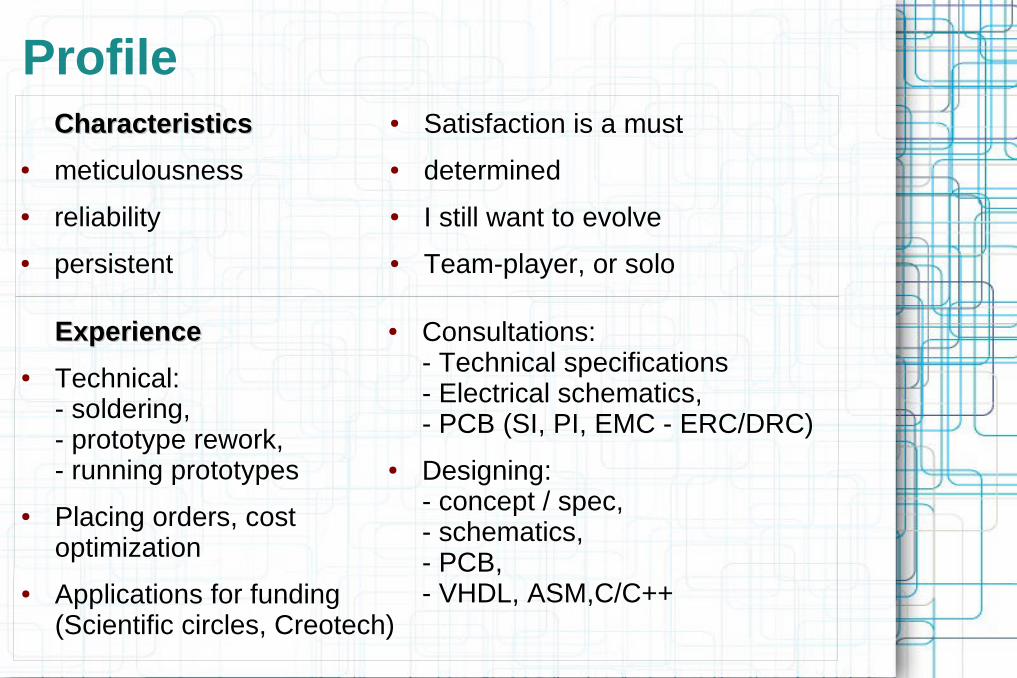
Profile
CharacteristicsCharacteristics
● meticulousness
● reliability
● persistent
● Consultations: - Technical specifications- Electrical schematics, - PCB (SI, PI, EMC - ERC/DRC)
● Designing: - concept / spec, - schematics, - PCB, - VHDL, ASM,C/C++
● Satisfaction is a must
● determined
● I still want to evolve
● Team-player, or solo
ExperienceExperience
● Technical: - soldering, - prototype rework, - running prototypes
● Placing orders, cost optimization
● Applications for funding (Scientific circles, Creotech)

Tenzin Gyatso, Dalai Lama 14
“If a problem can be solved it will be. If it can not be solved there
is no use worrying about it.”
http://www.dalailamaquotes.org
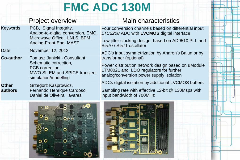
FMC ADC 130M
Keywords PCB, Signal Integrity, Analog-to-digital conversion, EMC, Microwave Office, LNLS, BPM, Analog-Front-End, MAST
Date November 12, 2012
Co-author Tomasz Janicki - ConsultantSchematic correction, PCB correction, MWO SI, EM and SPICE transient simulation/modelling
Other authors
Grzegorz Kasprowicz, Fernando Henrique Cardoso, Daniel de Oliveira Tavares
Project overview Main characteristicsFour conversion channels based on differential input LTC2208 ADC with LVCMOS digital interface
Low jitter clocking design, based on AD9510 PLL and Si570 / Si571 oscillator
ADC's input symmetrization by Anaren's Balun or by transformer (optional)
Power distribution network design based on uModule LTM8021 and LDO regulators for further analog/conversion power supply isolation
ADCs digital isolation by additional LVCMOS buffers
Sampling rate with effective 12-bit @ 130Msps with input bandwidth of 700MHz

FMC ADC 130M

FMC ADC 130M

FMC ADC 130M

FMC ADC 130M
ADC (conversion channel) analog input matching circuit. Default RC values and placement set according to Microwave SI, EM simulation
ADC's clock input matching circuit. Default RC values and placement set according to Microwave SI, EM simulation

FMC ADC 130M
TOP 3D view and PCB of input matching circuit with etched ground beneath (selected white region) in order to minimize parasitic capacitance influence. Each analog channel is isolated with grounding guards to minimize inter-channel coupling influence

FMC ADC 130M
Analog-digital power domain separation (BOT 3D view and power plane PCB desing). Split power plane is created immediately under ADC for shortest possible current drain/return path.
Power plane is further closely sandwiched with solid (not-split) ground plane. This creates buried capacitance with great frequency response qualities for fast current transient filtering.
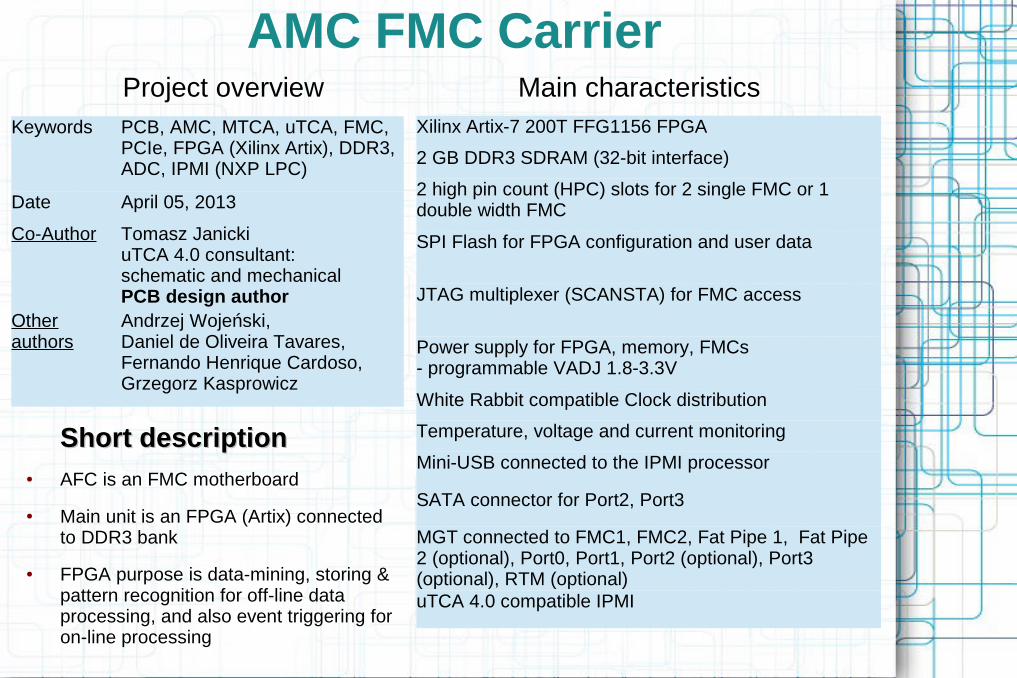
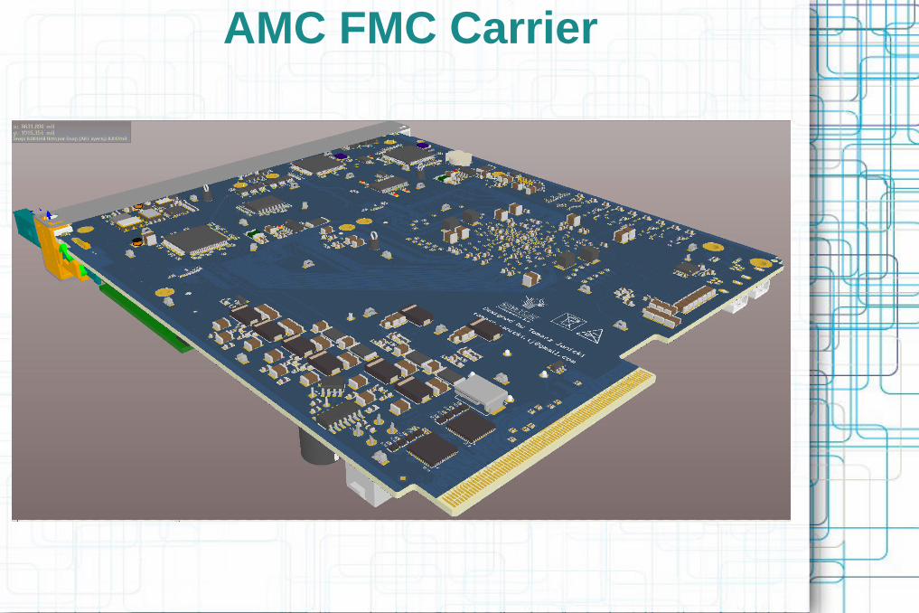
AMC FMC Carrier
Keywords PCB, AMC, MTCA, uTCA, FMC, PCIe, FPGA (Xilinx Artix), DDR3, ADC, IPMI (NXP LPC)
Date April 05, 2013
Co-Author Tomasz JanickiuTCA 4.0 consultant:schematic and mechanicalPCB design author
Other authors
Andrzej Wojeński, Daniel de Oliveira Tavares, Fernando Henrique Cardoso, Grzegorz Kasprowicz
Xilinx Artix-7 200T FFG1156 FPGA
2 GB DDR3 SDRAM (32-bit interface)
2 high pin count (HPC) slots for 2 single FMC or 1 double width FMC
SPI Flash for FPGA configuration and user data
JTAG multiplexer (SCANSTA) for FMC access
Power supply for FPGA, memory, FMCs - programmable VADJ 1.8-3.3V
White Rabbit compatible Clock distribution
Temperature, voltage and current monitoring
Mini-USB connected to the IPMI processor
SATA connector for Port2, Port3
MGT connected to FMC1, FMC2, Fat Pipe 1, Fat Pipe 2 (optional), Port0, Port1, Port2 (optional), Port3 (optional), RTM (optional)
uTCA 4.0 compatible IPMI
Short descriptionShort description
● AFC is an FMC motherboard
● Main unit is an FPGA (Artix) connected to DDR3 bank
● FPGA purpose is data-mining, storing & pattern recognition for off-line data processing, and also event triggering for on-line processing
Project overview Main characteristics

AMC FMC Carrier
Artix
FMC (HPC)SLOT 1
FMC (HPC)SLOT 2
DDR332-bit
SGMII 2
FAT PIPE 1
SGMII 1
FAT PIPE 2
SATA 2
SATA 1
CLOCKS
IPMI
JTAG
MLVDSbuffers
uC
SATA 2
SATA 1
MLVDS
AMCConnector
CL
OC
KS
WIT
CH
Simplified connections diagram
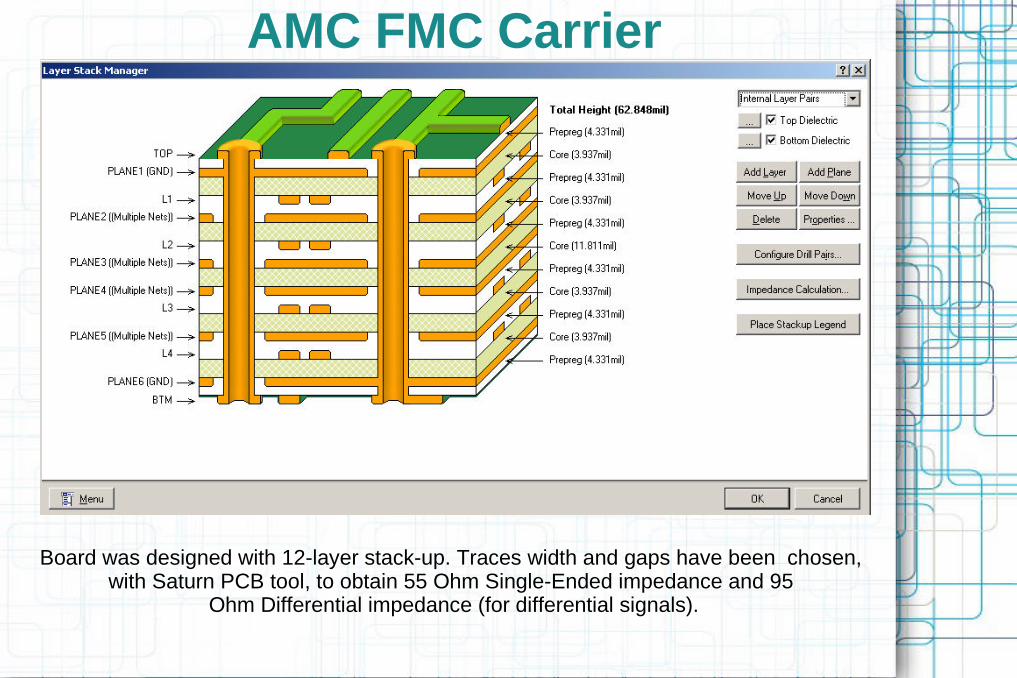
AMC FMC Carrier
Board was designed with 12-layer stack-up. Traces width and gaps have been chosen, with Saturn PCB tool, to obtain 55 Ohm Single-Ended impedance and 95
Ohm Differential impedance (for differential signals).
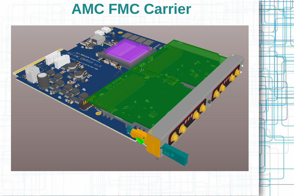
AMC FMC Carrier

AMC FMC Carrier
AMC FMC Carrier

AMC FMC Carrier

AMC FMC Carrier
DDR3 routing and length matching
AMC FMC Carrier
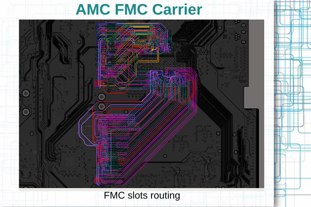
FMC slots routing

AMC FMC Carrier
DC/DC GND (yellow) polygon narrow connection, thus creating an isolation for high current return paths on TOP layer, where some strategic and more sensitive components reside.Wider GND connection is created through
vias into dedicated, not split layer beneath, This is a trade-off between controlling current return path and solid (less ground-bouncing) GND on TOP layer.

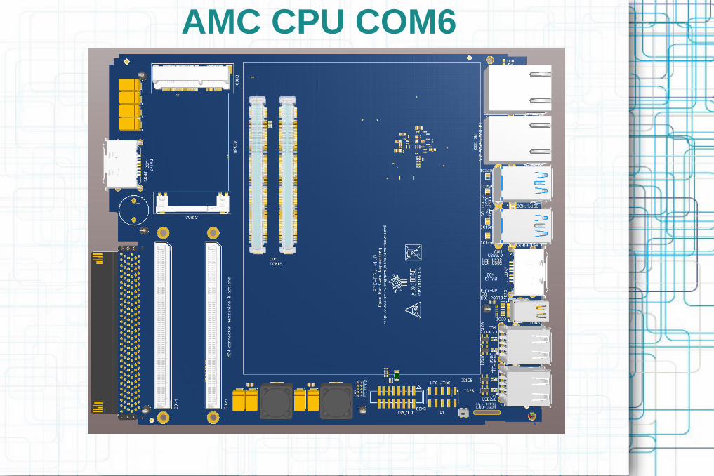
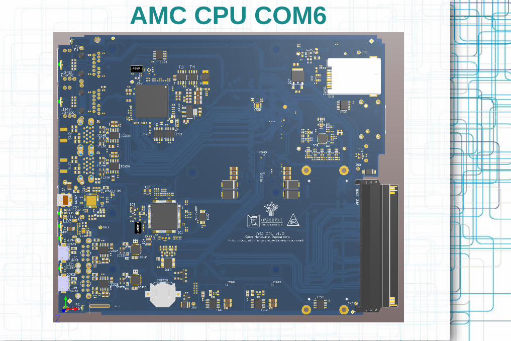
AMC CPU COM6 (ACC)
Keywords PCB, AMC, MTCA, uTCA, PCIe, COM EXPRESS, RTM, INTEL Ethernet Controller (GbE-PCIe Bridge), IPMI (LPC)
Date August 2, 2013
Co-Author Tomasz Janicki Schematic and PCB consultantPCB design
Other authors
Marcin Krzewski, Grzegorz Kasprowicz, Adrian Byszuk,
4 USB 2.0 ports and 4 USB 3.0 porst
Type 6 COM Express module
2 eSATA ports
custom RTM / MCH connector
2 Gigabit Ethernet ports
2 Gigabit Ethernet routed to uTCA Port 0 and Port1
Mini Display / HDMI Port
mPCIe socket
IPMI compatible
Short descriptionShort description
● ACC is COM6 motherboard
● Thanks to dedicated RTM/MCH link ACC can be an AMC or RTM board
● ACC equipped with COM6 module becomes a PC data server (storing & off-line processing) and/or uTCA crate controller.
Project overview Main characteristics

AMC CPU COM6
AMC ConnectorAMC Connector
COMeModule
DualUSB 2.0
DualUSB 2.0
DualUSB 3.0
DualUSB 3.0
SATA 1 SATA 2 HDMI 1
mPCIe Slot
HDMI 2 VGAGbE
1000TRS232
PCie
USB
Clock Buffer
CLK 0 REF 0 REF 1
CLK 1
CLK 2
CLK 4
CLK 5
CLK 6
CLK 7
REF CLK
RTM / MCH custom connectorRTM / MCH custom connector
uC
PCIex4
IPMIPCIe
x4SGMII SGMII
i350
GbE1000T
LPCPCIe
x1HDASPI
RS232
PCIex1
PCIex16
SATAPCIe
x1PCIe
x1CLK PCIe
x1
JTAG CLKsP2PMLVDSSATA SATA
Simplified connections diagram
AMC CPU COM6

AMC CPU COM6
AMC CPU COM6

AMC CPU COM6

AMC CPU COM6
Board was designed with 6-layer stack-up shown in Fig 8 - traces width and gaps have been chosen (with Saturn PCB tool) to obtain 50-55 Ohm Single-Ended impedance
and 95-105 Ohm Differential impedance for differential signals, and closely 50 Ohm for single-ended signals.

AMC CPU COM6

AMC CPU COM6
One-layer power distribution plane. Selected white-green is digital 3.3V, rest are analog (filtered, local) power islands. Power distribution plane has been designed to minimize the
required layers and with only couple of differential signals cross-over splits. In all-digital design it is a typical trade-of between a number of layers and a solid reference for
impedance controlled routing.

AMC CPU COM6
Small footprint DC/DC SMPS placement - PCB space vs EMC tradeoff

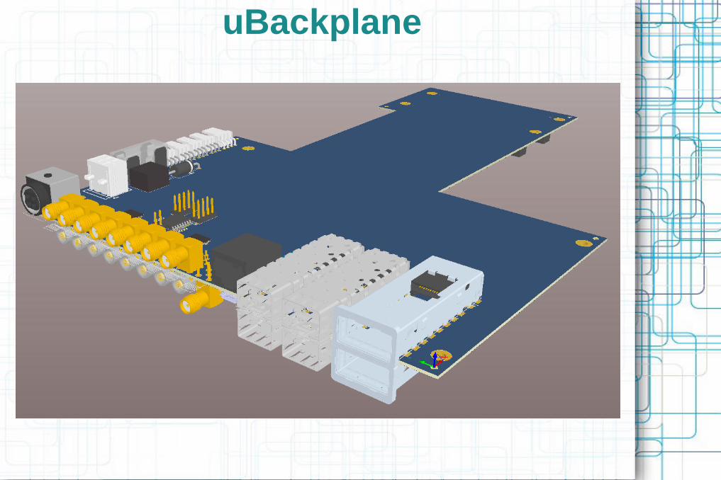
uBackplane
Keywords PCB, AMC, RTM, SFP, QSFP
Date Still under development, Schematics done April 4
Author Tomasz Janicki Schematic and PCB
Co-Authors
Grzegorz Kasprowicz
4 SFP+
2 QSFP+ (QSFP10)
8 SMA / LEMO MLVDS Bus
2 AMC slots
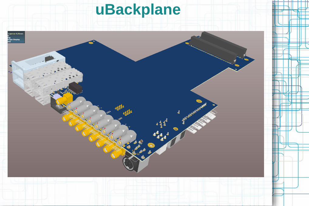
Rigid-Flex-Rigid PCB
10Mb Ethernet for management
Small form factor case, 19 inch rack 3-4U (mechanical case still under) development
Short descriptionShort description
● uBP is a laboratory backplane for two AMC modules – used for testing 1xAFC, 1xACC setup
● uBP is possible the cheapest and fully functional (yet smallest) uTCA backplane that one can have on the desk – made for uTCA / AMC related development
● QSFPs and/or SFPs (fiber connectivity) make uBP an interesting choice for "noisy" & space-limited environments
Project overview Main characteristics
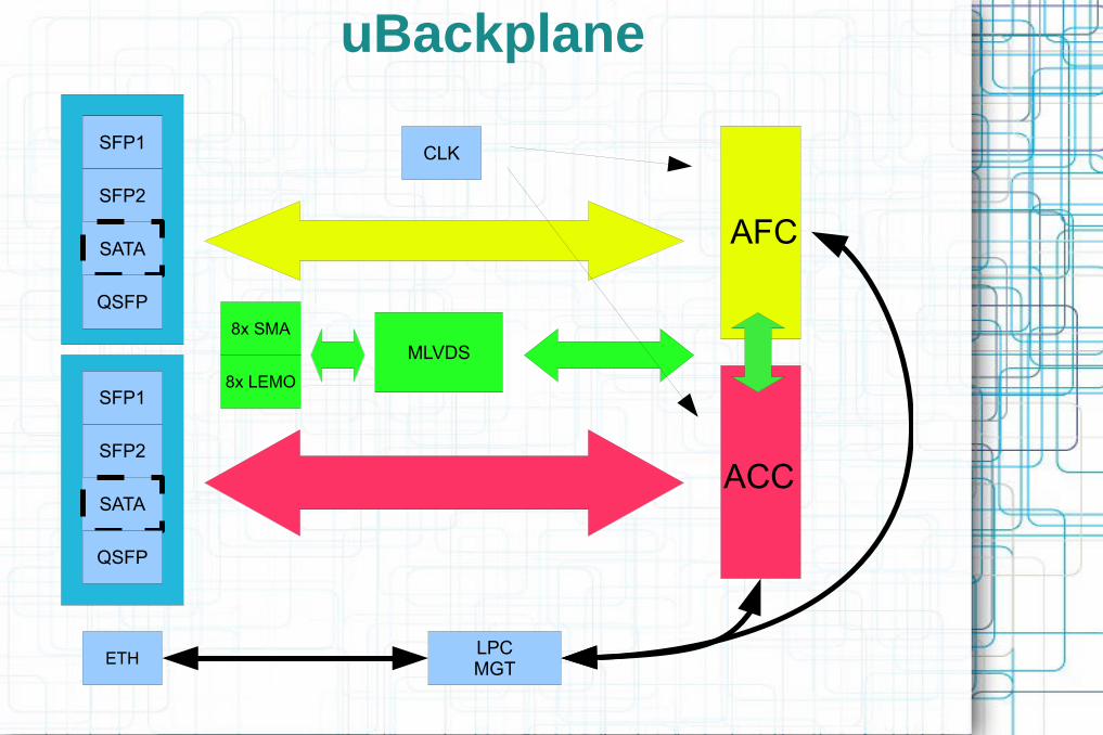
uBackplane
SFP1
SFP2
SFP1
SFP2
SATA
QSFP
SFP1
SFP2
SFP1
SFP2
SATA
QSFP
MLVDS
8x SMA
8x LEMO
LPCMGT
AFC
ACC
CLK
ETH
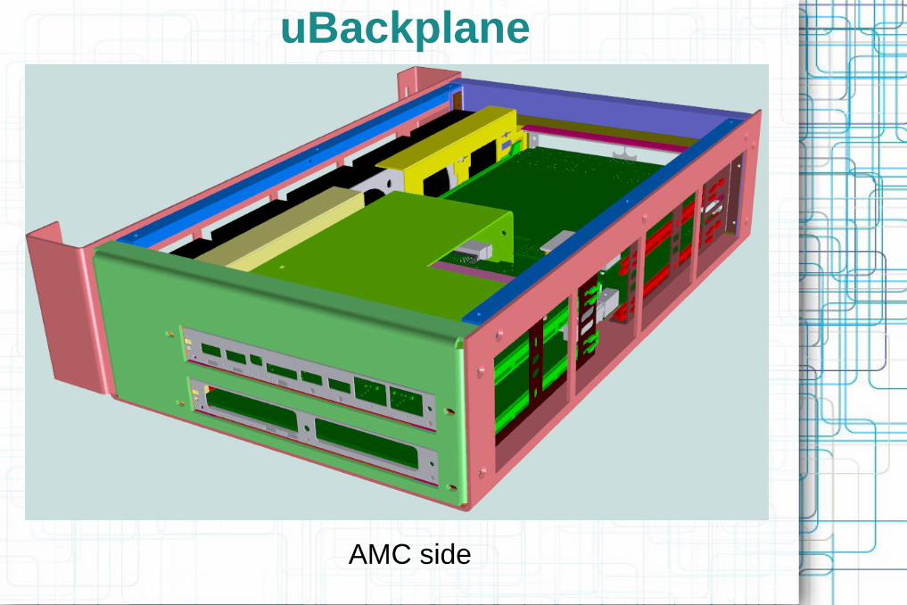
uBackplane
AMC side

uBackplane
RTM side

uBackplane
Rigid-Flex-Rigid Stack'up
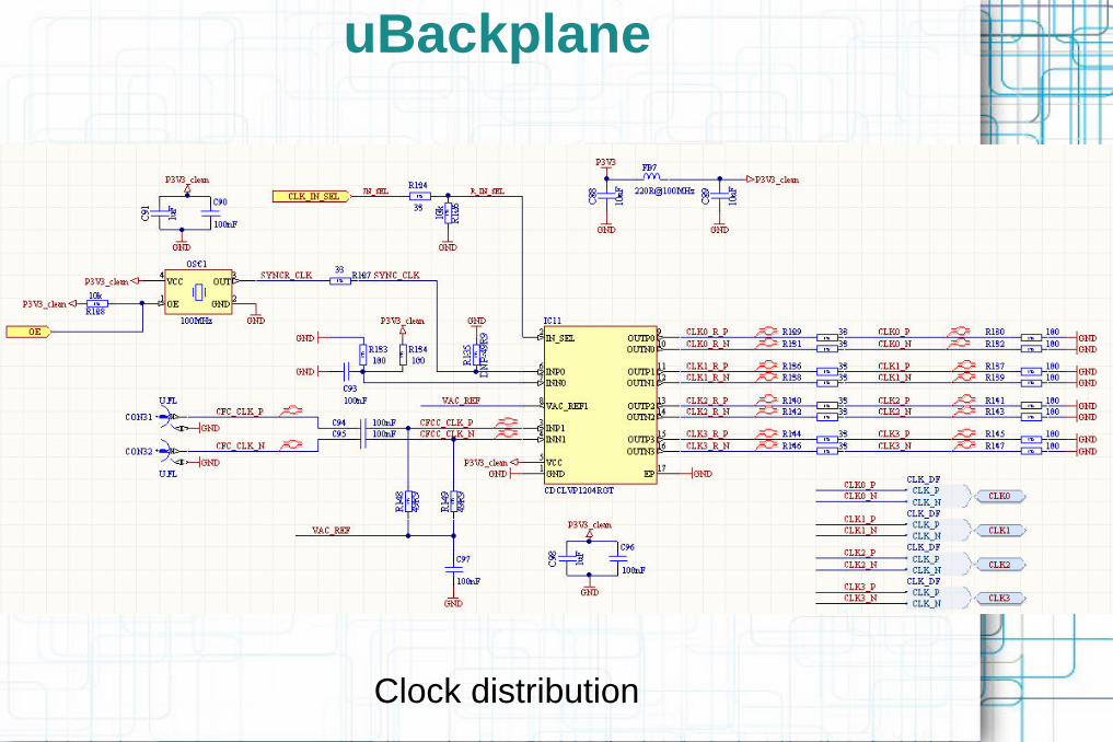
uBackplane
Clock distribution

uBackplane
Power distribution
uBackplane
uBackplane
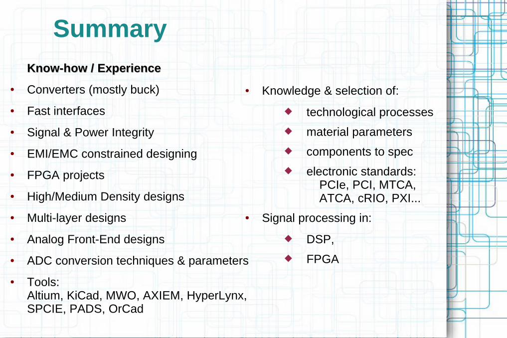
Summary
Know-how / ExperienceKnow-how / Experience
● Converters (mostly buck)
● Fast interfaces
● Signal & Power Integrity
● EMI/EMC constrained designing
● FPGA projects
● High/Medium Density designs
● Multi-layer designs
● Analog Front-End designs
● ADC conversion techniques & parameters
● Tools:Altium, KiCad, MWO, AXIEM, HyperLynx, SPCIE, PADS, OrCad
● Knowledge & selection of:
technological processes
material parameters
components to spec
electronic standards:PCIe, PCI, MTCA,ATCA, cRIO, PXI...
● Signal processing in:
DSP,
FPGA

Done