
Outlet Flow Velocity in Circular Culvert - Start Flow Velocity in Circular Culvert Wojciech...
11
Archives of Hydro-Engineering and Environmental Mechanics Vol. 61 (2014), No. 3–4, pp. 193–203 DOI: 10.1515/heem-2015-0013 © IBW PAN, ISSN 1231–3726 Outlet Flow Velocity in Circular Culvert Wojciech Szpakowski Gdańsk University of Technology, Faculty of Civil and Environmental Engineering, ul. G. Narutowicza 11/12, 80-233 Gdańsk, Poland, e-mail: [email protected] (Received October 10, 2014; revised December 16, 2014) Abstract The outlet flow velocity in the end section of the culvert barrel depends in most cases on the culvert geometry, including the barrel slope, as well as on upstream and downstream channel parameters. Flowing water can create pressure flow or free surface flow in the culvert barrel. In the case of an unsubmerged barrel outlet, the free-surface flow is more frequent than the full flow. Increased velocities can cause channel bed scour and bank erosion downstream of the culvert outlet. Different culvert flow cases in which the barrel outlet is unsubmerged are presented in this paper. The influence of the flow regime on the outlet velocity is also discussed. Key words: culvert conveyance, outlet velocity, circular culvert, critical flow List of Symbols A – cross-sectional area of flow [m 2 ], A D – full cross-sectional area of culvert barrel [m 2 ], B – width of water surface [m], D – interior height of culvert barrel [m], g – gravitational constant [m/s 2 ], H – upstream headwater [m], h – water depth [m], h C – critical depth [m], h d – tailwater [m], h N – normal depth [m], h Lc – contraction coefficient associated with water passing under the culvert soffit [m], i C – critical slope [–], i 0 – culvert barrel slope [–], n – Manning roughness coefficient [m -1/3 s], O z – wetted perimeter [m], Q – discharge [m 3 /s],
Transcript of Outlet Flow Velocity in Circular Culvert - Start Flow Velocity in Circular Culvert Wojciech...
Archives of Hydro-Engineering and Environmental MechanicsVol. 61 (2014), No. 3–4, pp. 193–203
DOI: 10.1515/heem-2015-0013© IBW PAN, ISSN 1231–3726
Outlet Flow Velocity in Circular Culvert
Wojciech Szpakowski
Gdańsk University of Technology, Faculty of Civil and Environmental Engineering,ul. G. Narutowicza 11/12, 80-233 Gdańsk, Poland, e-mail: [email protected]
(Received October 10, 2014; revised December 16, 2014)
AbstractThe outlet flow velocity in the end section of the culvert barrel depends in most cases on theculvert geometry, including the barrel slope, as well as on upstream and downstream channelparameters. Flowing water can create pressure flow or free surface flow in the culvert barrel.In the case of an unsubmerged barrel outlet, the free-surface flow is more frequent than thefull flow. Increased velocities can cause channel bed scour and bank erosion downstream ofthe culvert outlet. Different culvert flow cases in which the barrel outlet is unsubmerged arepresented in this paper. The influence of the flow regime on the outlet velocity is also discussed.
Key words: culvert conveyance, outlet velocity, circular culvert, critical flow
List of Symbols
A – cross-sectional area of flow [m2],AD – full cross-sectional area of culvert barrel [m2],B – width of water surface [m],D – interior height of culvert barrel [m],g – gravitational constant [m/s2],H – upstream headwater [m],h – water depth [m],hC – critical depth [m],hd – tailwater [m],hN – normal depth [m],hLc – contraction coefficient associated with water passing under the culvert
soffit [m],iC – critical slope [–],i0 – culvert barrel slope [–],n – Manning roughness coefficient [m−1/3s],Oz – wetted perimeter [m],Q – discharge [m3/s],
194 W. Szpakowski
vC – critical flow velocity [m/s],vout – outlet flow velocity [m/s],z – datum and inlet invert difference [m],α – Saint-Venant coefficient [–],β – centre angle [◦, rad],βc – centre angle corresponding to the critical flow [◦, rad].
1. Introduction
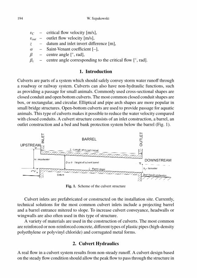
Culverts are parts of a system which should safely convey storm water runoff througha roadway or railway system. Culverts can also have non-hydraulic functions, suchas providing a passage for small animals. Commonly used cross-sectional shapes areclosed conduit and open bottom culverts. The most common closed conduit shapes arebox, or rectangular, and circular. Elliptical and pipe arch shapes are more popular insmall bridge structures. Open-bottom culverts are used to provide passage for aquaticanimals. This type of culverts makes it possible to reduce the water velocity comparedwith closed conduits. A culvert structure consists of an inlet construction, a barrel, anoutlet construction and a bed and bank protection system below the barrel (Fig. 1).
Fig. 1. Scheme of the culvert structure
Culvert inlets are prefabricated or constructed on the installation site. Currently,technical solutions for the most common culvert inlets include a projecting barreland a barrel entrance mitered to slope. To increase culvert conveyance, headwalls orwingwalls are also often used in this type of structure.
A variety of materials are used in the construction of culverts. The most commonare reinforced or non-reinforced concrete, different types of plastic pipes (high-densitypolyethylene or polyvinyl chloride) and corrugated metal forms.
2. Culvert Hydraulics
A real flow in a culvert system results from non-steady runoff. A culvert design basedon the steady flow condition should allow the peak flow to pass through the structure in
Outlet Flow Velocity in Circular Culvert 195
a safe way. Sudden changes in the velocity-depth relationship, and rapidly varied flowcan often be observed in the culvert vicinity and inside the barrel. In most cases, thewater flow upstream of the culvert is subcritical. Water contraction in the vicinity ofthe culvert entrance causes local energy loss. Inside a partly filled culvert, water flowcan be subcritical, critical or supercritical. Water can also fill the barrel volume par-tially or entirely. Whenever flow changes from supercritical to subcritical, hydraulicjumps will form either inside the barrel or downstream of the culvert structure.
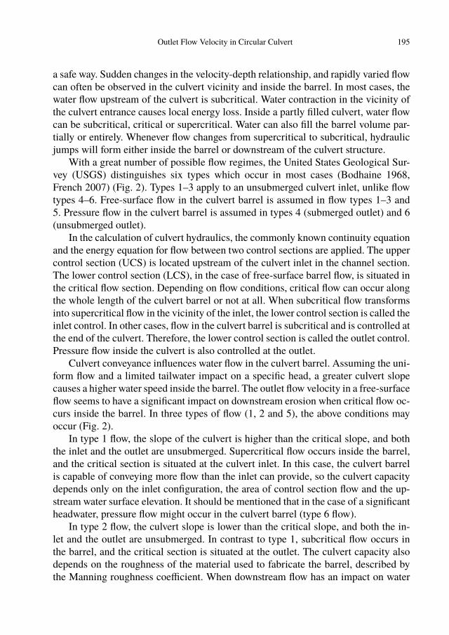
With a great number of possible flow regimes, the United States Geological Sur-vey (USGS) distinguishes six types which occur in most cases (Bodhaine 1968,French 2007) (Fig. 2). Types 1–3 apply to an unsubmerged culvert inlet, unlike flowtypes 4–6. Free-surface flow in the culvert barrel is assumed in flow types 1–3 and5. Pressure flow in the culvert barrel is assumed in types 4 (submerged outlet) and 6(unsubmerged outlet).
In the calculation of culvert hydraulics, the commonly known continuity equationand the energy equation for flow between two control sections are applied. The uppercontrol section (UCS) is located upstream of the culvert inlet in the channel section.The lower control section (LCS), in the case of free-surface barrel flow, is situated inthe critical flow section. Depending on flow conditions, critical flow can occur alongthe whole length of the culvert barrel or not at all. When subcritical flow transformsinto supercritical flow in the vicinity of the inlet, the lower control section is called theinlet control. In other cases, flow in the culvert barrel is subcritical and is controlled atthe end of the culvert. Therefore, the lower control section is called the outlet control.Pressure flow inside the culvert is also controlled at the outlet.
Culvert conveyance influences water flow in the culvert barrel. Assuming the uni-form flow and a limited tailwater impact on a specific head, a greater culvert slopecauses a higher water speed inside the barrel. The outlet flow velocity in a free-surfaceflow seems to have a significant impact on downstream erosion when critical flow oc-curs inside the barrel. In three types of flow (1, 2 and 5), the above conditions mayoccur (Fig. 2).
In type 1 flow, the slope of the culvert is higher than the critical slope, and boththe inlet and the outlet are unsubmerged. Supercritical flow occurs inside the barrel,and the critical section is situated at the culvert inlet. In this case, the culvert barrelis capable of conveying more flow than the inlet can provide, so the culvert capacitydepends only on the inlet configuration, the area of control section flow and the up-stream water surface elevation. It should be mentioned that in the case of a significantheadwater, pressure flow might occur in the culvert barrel (type 6 flow).
In type 2 flow, the culvert slope is lower than the critical slope, and both the in-let and the outlet are unsubmerged. In contrast to type 1, subcritical flow occurs inthe barrel, and the critical section is situated at the outlet. The culvert capacity alsodepends on the roughness of the material used to fabricate the barrel, described bythe Manning roughness coefficient. When downstream flow has an impact on water
196 W. Szpakowski
Fig. 2. Six basic types of culvert flow, UCS – Upper control section, LCS – Lower controlsection. (Based on Bodhaine (1968))
Outlet Flow Velocity in Circular Culvert 197
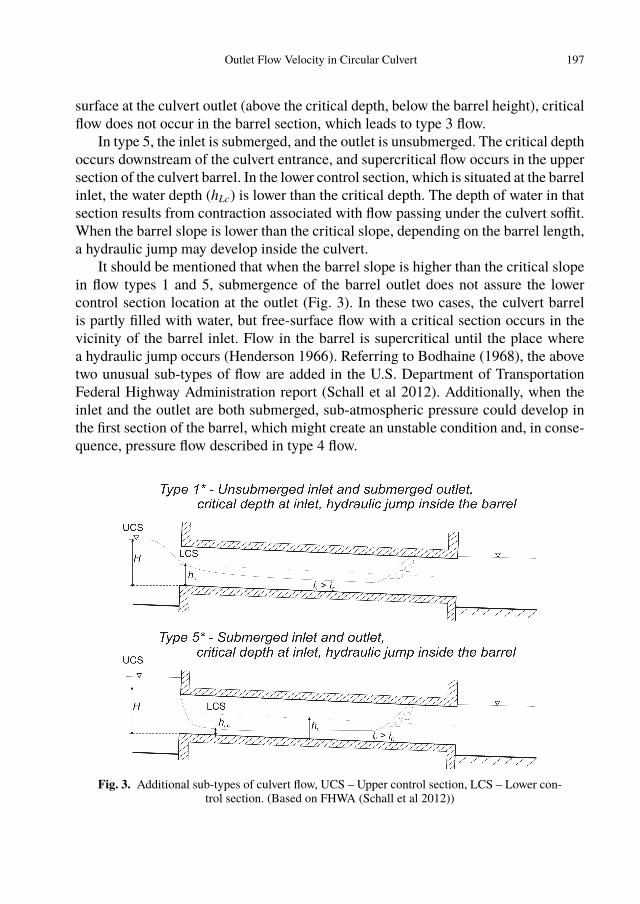
surface at the culvert outlet (above the critical depth, below the barrel height), criticalflow does not occur in the barrel section, which leads to type 3 flow.
In type 5, the inlet is submerged, and the outlet is unsubmerged. The critical depthoccurs downstream of the culvert entrance, and supercritical flow occurs in the uppersection of the culvert barrel. In the lower control section, which is situated at the barrelinlet, the water depth (hLc) is lower than the critical depth. The depth of water in thatsection results from contraction associated with flow passing under the culvert soffit.When the barrel slope is lower than the critical slope, depending on the barrel length,a hydraulic jump may develop inside the culvert.
It should be mentioned that when the barrel slope is higher than the critical slopein flow types 1 and 5, submergence of the barrel outlet does not assure the lowercontrol section location at the outlet (Fig. 3). In these two cases, the culvert barrelis partly filled with water, but free-surface flow with a critical section occurs in thevicinity of the barrel inlet. Flow in the barrel is supercritical until the place wherea hydraulic jump occurs (Henderson 1966). Referring to Bodhaine (1968), the abovetwo unusual sub-types of flow are added in the U.S. Department of TransportationFederal Highway Administration report (Schall et al 2012). Additionally, when theinlet and the outlet are both submerged, sub-atmospheric pressure could develop inthe first section of the barrel, which might create an unstable condition and, in conse-quence, pressure flow described in type 4 flow.
Fig. 3. Additional sub-types of culvert flow, UCS – Upper control section, LCS – Lower con-trol section. (Based on FHWA (Schall et al 2012))
198 W. Szpakowski
3. Hydraulic Parameters of a Circular Culvert Barrel
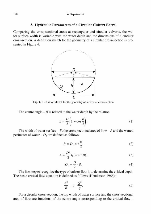
Comparing the cross-sectional areas at rectangular and circular culverts, the wa-ter surface width is variable with the water depth and the dimensions of a circularcross-section. A definition sketch for the geometry of a circular cross-section is pre-sented in Figure 4.
Fig. 4. Definition sketch for the geometry of a circular cross-section
The centre angle – β is related to the water depth by the relation
h =D2
(1 − cos
β
2
), (1)
The width of water surface – B, the cross-sectional area of flow – A and the wettedperimeter of water – Oz are defined as follows:
B = D · sinβ
2, (2)
A =D2
8(β − sin β) , (3)
Oz =D2· β. (4)
The first step to recognize the type of culvert flow is to determine the critical depth.The basic critical flow equation is defined as follows (Henderson 1966):
A3
B= α ·
Q2
g. (5)
For a circular cross-section, the top width of water surface and the cross-sectionalarea of flow are functions of the centre angle corresponding to the critical flow –
Outlet Flow Velocity in Circular Culvert 199
βc. These two critical cross-sectional hydraulic parameters are defined similarly toequations 2 and 3. The critical flow equation for a circular cross-section is defined asa nonlinear equation:
D5
512· (βc − sin βc)3 =
α · Q2
g· sin
βc
2. (6)
After rearranging the above equation in the form f (βc) = 0, the following formulais obtained:
f (βc) =D5
512· (βc − sin βc)3 −
α · Q2
g· sin
βc
2= 0. (7)
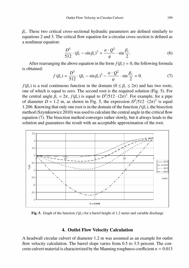
f (βc) is a real continuous function in the domain (0 ≤ βc ≤ 2π) and has two roots,one of which is equal to zero. The second root is the required solution (Fig. 5). Forthe central angle βc = 2π, f (βc) is equal to D5/512 · (2π)3. For example, for a pipeof diameter D = 1.2 m, as shown in Fig. 5, the expression D5/512 · (2π)3 is equal1.206. Knowing that only one root is in the domain of the function f (βc), the bisectionmethod (Szymkiewicz 2010) was used to calculate the central angle in the critical flowequation (7). The bisection method converges rather slowly, but it always leads to thesolution and guarantees the result with an acceptable approximation of the root.
Fig. 5. Graph of the function f (βc) for a barrel height of 1.2 meter and variable discharge
4. Outlet Flow Velocity Calculation
A headwall circular culvert of diameter 1.2 m was assumed as an example for outletflow velocity calculation. The barrel slope varies from 0.5 to 3.5 percent. The con-crete culvert material is characterized by the Manning roughness coefficient n = 0.013
200 W. Szpakowski
m−1/3s, which corresponds to a new concrete surface. The culvert outlet is unsub-merged without any impact of downstream. For the unsubmerged inlet, the first typeof culvert flow was used. When the headwater caused the submergence of the culvertentrance, type 5 flow was used.
The FHWA formulas were used in flow discharge calculations (Schall et al 2012).For the inlet control equation valid in the unsubmerged inlet flow (type 1 flow), basedon the specific head at the critical depth, the FHWA formula has the following form:
HD=
(hC +
v2C
2g
)D
+ 0.0078[1.811 · QAD · D0.5
]2.0
− 0.5 · i0. (8)
In the second term on the right-hand side of equation(8), the correction factors0.0078 and 2.0 were determined on the basis of a real experiment conducted by theNational Bureau of Standards (NBS) and commissioned by the U.S. Bureau of PublicRoads. The number 1.811 results from metric to SI system unit conversion. Thereis also an element in equation (8) which designates the slope of the culvert barrel.However, this parameter has little effect on the final result. Equation (8) applies upto about Q/ADD0.5 = 1.93, which corresponds to a headwater-pipe diameter ratio ofabout 1.1.
For the submerged culvert entrance (type 5 flow), the FHWA formula includingtwo correction factors (0.0379 and 0.69) and a metric-SI unit conversion parameter,is written as follows:
HD= 0.0379
[1.811 · QAD · D0.5
]2
+ 0.69 − 0.5 · i0. (9)
Equation (9) applies above about Q/ADD0.5 = 2.21, which corresponds to a head-water-pipe diameter ratio of about 1.3. A direct relationship between headwater andculvert discharge was obtained for the submerged inlet condition (Eq. 9). For the un-submerged condition, the culvert discharge value was initially assumed. The criticaldepth was estimated, and the headwater depth above the inlet control section invertwas calculated by equation (8).
The outlet flow velocity was calculated as the mean velocity of flow at the outletby the basic continuity equation using culvert discharge and the cross-sectional areaof flow:
vout =QA. (10)
For a barrel slope higher than the critical slope in the unsubmerged inlet condition(type 1 flow) or the submerged inlet condition (type 5 flow), supercritical flow occursin the culvert barrel. In these two cases, the cross-sectional area of flow depends onthe water depth in the channel barrel, which is assumed as the normal depth calculatedfrom the Manning formula for a circular cross-section:
Outlet Flow Velocity in Circular Culvert 201
Q =1n·
D2
8(β − sin β) ·
(D4B
(β − sin β))2/3
· i1/20 , (11)
where the centre angle β corresponding to the normal depth is calculated from therearranged form of equation (1):
β = 2 · a cos(1 −
2hN
D
). (12)
The solution of non-linear equation (11) in the real domain (0 ≤ hN ≤ D) wasobtained by the bisection method (Szymkiewicz 2010).
For the unsubmerged inlet condition and subcritical flow in the barrel, the criticaldepth occurs in the outlet. In equation (10), the cross-sectional area of flow is equalto the critical area of flow. For critical flow, the outlet flow velocity was calculated byequation (3).
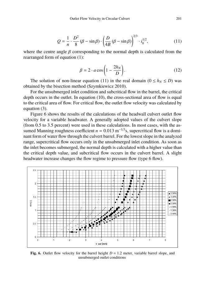
Figure 6 shows the results of the calculations of the headwall culvert outlet flowvelocity for a variable headwater. A generally adopted values of the culvert slope(from 0.5 to 3.5 percent) were used in these calculations. In most cases, with the as-sumed Manning roughness coefficient n = 0.013 m−1/3s, supercritical flow is a domi-nant form of water flow through the culvert barrel. For the lowest slope in the analyzedrange, supercritical flow occurs only in the unsubmerged inlet condition. As soon asthe inlet becomes submerged, the normal depth is calculated with a higher value thanthe critical depth value, and subcritical flow occurs in the culvert barrel. A slightheadwater increase changes the flow regime to pressure flow (type 6 flow).
Fig. 6. Outlet flow velocity for the barrel height D = 1.2 meter, variable barrel slope, andunsubmerged outlet conditions
202 W. Szpakowski
For higher values of the culvert slope, the outlet velocity increases. Assumingthat the headwater height is twice the height of the barrel and with a culvert slope of3.5%, the outlet velocity can exceed 6.5 meter per second under unsubmerged outletconditions when there is no tailwater impact on barrel flow. Such a high velocity isundesirable because of downstream scour, which can be dangerous for the culvert andthe road structure.
5. Conclusions
In culvert design, one should avoid sudden rises in the headwater resulting from un-predictable changes between inlet, outlet and barrel flow control. The first step is toestimate the culvert discharge value, which requires the knowledge of hydrologicalprocesses. Natural conditions, such as the channel slope, limit culvert design pos-sibilities. Depending on hydraulic parameters such as headwater, tailwater, criticaldepth and normal depth, the appropriate type of flow has to be selected for calcula-tions to match actual conditions. One of the results of culvert design is the estimatedoutlet velocity. Because of the possible erosion of streambed or bank material due toflowing water, the outlet velocity should be limited to safe values of 0.45 m/s for clay,1.0 m/s for gravel and about 2.0 m/s for concrete and schist (Sawicki 2009). Polishregulations on culvert design published by the Minister of Transport and MaritimeAffairs in 2000 (Journal of Laws of 2000, No. 63, item 735) suggest an allowablespeed in the culvert of 3 or 3.5 m/s (depending on the height of the culvert barrel).Unfortunately, under natural conditions in river valleys, hills and mountainous areas,the natural channel slope can be significant, which may result in huge outlet velocitiesand consequently in bottom scour processes downstream. In such cases, it is necessaryto dissipate much of the energy by dissipators, such as stilling basins or vertical wells,which can dissipate energy without damage.
Depending on the hydraulic type of culvert water flow, the outlet velocity wascalculated on the basis of the normal depth or the critical depth. However, owing tothe assumed lack of impact of downstream on the culvert outlet, the real outlet velocitymay reach higher values. This fact is included in Polish regulations (Journal of Lawsof 2000, No. 63, item 735) as a correction parameter to calculated outlet depths.
The above-mentioned regulation on the technical conditions to be met by roadengineering structures and their location states that, comparing with FHWA, onlyfour types of culvert flow are included in a hydraulic calculations (types 2, 4–6).A comparison of the two documents shows that the regulations published by the Mi-nister of Transport and Maritime Affairs recommend higher dimensions of the culvertcross-section with respect to the same data (Szpakowski 2013). For the unsubmergedinlet condition of flow, where supercritical flow occurs in the culvert barrel or there isa tailwater impact on barrel flow, the Polish law does not provide a clear recommen-dation for culvert design.
Outlet Flow Velocity in Circular Culvert 203
ReferencesBodhaine G. L. (1968) (first printing) Measurement of Peak Discharge at Culverts by Indirect Methods.
Techniques of Water Resources Investigation of the United States Geological Survey, U.S. Geolog-ical Survey, Washington.
Chanson H. (2004) The hydraulics of open channel flow: an introduction, Elsevier, Oxford.Henderson F. M. (1966) Open Channel Flow, Macmillan publishing,New York, London.French R. H. (2007) Open Channel Hydraulics, Water Resources Publications, LLC.Regulation published by the Minister of Transport and Maritime Affairs on technical conditions to be
met by traffic engineering structures and their location (Journal of Laws of 2000, No. 63, item 735)(in Polish).
Sawicki J. (2009) Flow mechanics, Wydawnictwo PG, Gdańsk (in Polish).Schall J. D., Thompson P. L., Zerges S. M., Kilgore R. T., Morris J. L. (2012) Hydraulic de-
sign of highway culverts, U.S. Department of Transportation, Federal Highway AdministrationFHWA-HIF-12-026.
Szpakowski W. (2013) Estimation of the actual capacity of a road culvert, Drogownictwo, LXVIII (6),189–192 (in Polish).
Szymkiewicz R. (2010) Numerical Modeling in Open Channel Hydraulics, Springer, Dordrecht, Hei-delberg, London, New York.


![Bibliographie II Christoph Markschies33) Laudator optimus maximus [Dieter Simon], in: Circular. Berlin-Brandenburgischen Akademie der Wissenschaften, 10. Jahrgang, Heft Nr. 32, S.](https://static.fdocuments.pl/doc/165x107/5b9fe78109d3f242318bc663/bibliographie-ii-christoph-33-laudator-optimus-maximus-dieter-simon-in-circular.jpg)