
Notatki SEE Przyszlosci
169
SEE przyszłości, Smartgrids itp. – wybrane artykuły {Metoda predykcyjna na bazie PMU – rok 1995} PREDICTING FUTURE BEHAVIOR OF TRANSIENT EVENTS RAPIDLY ENOUGH TO EVALUATE REMEDIAL CONTROL OPTIONS IN REALTIME Steven Rovnyak* Chih-Wen Liu* Jin Lu** Weimin Ma* James Thorp IEEE Transactions on Power Systems, Vol. 10, No. 3, August 1995 Keywords; Clustering, estimation, integration, pattern recognition, phasor measurements, transient stability. ABSTRACT - Electric utilities are becoming increasingly interested in using synchronized phasor measurements from around the system to enhance their protection and remedial action control strategies. Accordingly the task of predicting future behavior of the power system before it actually occurs has become an important area of research. This paper presents and analyses several approaches for solving the real-time prediction problem. The first method clusters the initial post- fault swing curves into coherent groups and fits a low order equivalent model to the specific transient event in progress. The model is updated with each new set of phasor measurements and provides a running prediction of future behavior which is valid for approximately 1/2 second into the future. We show how this capability would be useful inside the framework of a protection scheme such as the proposed French Defence Plan. If, on the other hand, a relatively detailed reduced-odex model is available ahead of time. then it could be used to predict future behavior for several different control options. The task in this case is to solve the model much faster than real-time using the post-fault phasor measurements as the initial condition. In order to solve systems with detailed load models fast enough for real-time prediction. we present a new piecewise constant current load model approximation technique that can solve a model as complex as the New England 39 bus system with composite voltage dependent loads much faster than real-time. If the reduced order model is too large for real- time solution, then a pattern recognition tool such as decision trees can be trained off line to associate the post-fault phasor measurements with the outcome of future behavior. In 1
-
Upload
desire-dauphin-rasolomampionona -
Category
Documents
-
view
119 -
download
2
Transcript of Notatki SEE Przyszlosci

SEE przyszłości, Smartgrids itp. – wybrane artykuły
{Metoda predykcyjna na bazie PMU – rok 1995}
PREDICTING FUTURE BEHAVIOR OF TRANSIENT EVENTS RAPIDLY ENOUGH TO EVALUATE REMEDIAL CONTROL OPTIONS IN REALTIMESteven Rovnyak* Chih-Wen Liu* Jin Lu** Weimin Ma* James ThorpIEEE Transactions on Power Systems, Vol. 10, No. 3, August 1995
Keywords; Clustering, estimation, integration, pattern recognition, phasor measurements, transient stability.
ABSTRACT - Electric utilities are becoming increasingly interested in using synchronized phasor measurements from around the system to enhance their protection and remedial action control strategies. Accordingly the task of predicting future behavior of the power system before it actually occurs has become an important area of research. This paper presents and analyses several approaches for solving the real-time prediction problem. The first method clusters the initial post-fault swing curves into coherent groups and fits a low order equivalent model to the specific transient event in progress. The model is updated with each new set of phasor measurements and provides a running prediction of future behavior which is valid for approximately 1/2 second into the future. We show how this capability would be useful inside the framework of a protection scheme such as the proposed French Defence Plan.If, on the other hand, a relatively detailed reduced-odex model is available ahead of time. then it could be used to predict future behavior for several different control options. The task in this case is to solve the model much faster than real-time using the post-fault phasor measurements as the initial condition. In order to solve systems with detailed load models fast enough for real-time prediction. we present a new piecewise constant current load model approximation technique that can solve a model as complex as the New England 39 bus system with composite voltage dependent loads much faster than real-time. If the reduced order model is too large for real-time solution, then a pattern recognition tool such as decision trees can be trained off line to associate the post-fault phasor measurements with the outcome of future behavior. In this case also. the piecewise constant current technique would be needed to perform the off-line training set generation with sufficient speed and accuracy.
1. INTRODUCTIONSynchronized phasor measurement units (PMU's) simultaneously measure state variables in remote locations of the power system network [l]. The phasors obtained from a period or more of samples from all three phases provide a precise estimate of the positive sequence voltage phasor at each installation. Commercially available systems based on Global Positioning System (GPS) satellite time transmissions can provide synchronization to 1 microsecond accuracy, which means that relative phase angles can be measured to a precision of 0.02 electrical degrees [2]. Utility experience indicates that communication systems can transmit these time-tagged phasor measurements to a central location every 5 cycles [3]. It is therefore possible to track the relative phase angles of important state variables in real-time.An emerging application of this technology is to track the state of the system immediately following a transient event in order to select an appropriate remedial control action. One such real-time control strategy is already being implemented at the Florida-Georgia interface [4]. and others are currently under development [5]. This research was performed under a subcontract of the Florida-Georgia project, which was sponsored by EPRI and installed at the interface between the two regions. An important feature. of the Florida-Georgia situation is
1

that inter-area oscillations between the two regions can always be modeled as a two-machine equivalent system. When such oscillations are initiated, phasor measurements are taken within Florida and Georgia m order to infer the corresponding state of the two-machine equivalent Future stability is then detennined by applying the equal area criterion. This prediction is used for adaptive out-of-step relaying at the Florida-Georgia interface.2. REAL-TIMEPREDICTIONOur research addressed the question of accomplishing out-of-step prediction when the system does not always reduce to a previously known two-machine equivalent. Possible methods of approaching this problem which we have researched fall into two broad categories:(1) Infer a small-size (e.g. 2, 3 or 4 machine) equivalent from the post-fault phasor measurements, which models the particular mode of oscillation of the fault in progress. Solve the model forward in time in order to predict future behavior.(2) Use a reduced-order but relatively detailed model of the system (e.g. the 39 bus model for New England) which adequately covers the many modes of oscillation initiated by different contingencies. Solve the model faster than real time if computational resources permit, or else train a pattern recognition tool off-line in order to associate in real-time the post-fault phasor measurements with the outcome of future behavior. 2.1 Clustering-Estimation-Integration (CEO)The fmt strategy is accomplished, in a limited fashion, without any prior knowledge about the system on which it is performed. Section 3 in this paper presents a method for deducing in real-time which machines are swinging together. and estimating the parameters of a 2. 3 or 4 machine equivalent which is then solved faster than real-time. This technique would be useful inside the framework of the proposed French Defence Plan which will utilize phasor measurements to guard against losses of synchronism [5,6]. The objective of this plan is U, implement a controlled separation of the system into "islandable" areas whenever a loss of synchronism is detected by the PMUs. An issue of critical importance in this scheme is the amount of time between the detection of phase angle opposition and the implementation of islanding. Given the technological constraint acceptable. This time scale, it should be noted, is much faster than the operation of standard under-frequency relays. In a panel discussion on phasor measurement applications at the 1993 PES Summer Meeting, a representative of Electricité de France [7] mentioned the difficulty in reacting quickly enough to the detection of loss of synchronism, and indicated the desirability of predicting future behavior. Accordingly, we show that the proposed technique can reliably predict losses of synchronism a short time into the future.As illustrated in Section 3. our clustering - estimation - integration (CEI) technique can be used to provide a continually updated prediction window extending approximately half a second into the future. Instead of waiting for physical loss of synchronism to occur, it would be possible to act in advance on the basis of future predicted behavior. We simulate the capability of the CEI prediction technique in giving advance warning of loss of synchronism and show that it can predict with some accuracy which generators will go over and under-speed. This is enough information to implement the controlled separation ahead of time. The performance is not perfect, but the errors that do occur tend to be tolerable. For example, if a subset of the over-speed generators are separating faster than the rest, then the algorithm will predict at first that only these will go over-speed. However such errors could be a c u n n m M by resuming prediction for the remaining machines. And Mermore. if the system can only be islanded in a limited number of ways, then it would still make sense to separate the areas containing the most rapidly diverging machines. Another source of error is that the length of advance warning before loss of synchronism is not uniform, and occasionally there is no warning. As a consequence the CEI algorithm must be viewed as a potential augmentation to
2
a scheme such as the Defence Plan. which will improve reaction times in many cases, and will cause little or no harm in others.……………5. CONCLUSIONSThe ability to obtain synchronized phasor measurements from around the system is expected to enable improved emergency response for maintaining system reliability. At the minimum, it seems that one should be able to predict with moderate accuracy what is going to happen in the near future following a transient event If one could predict what would happen under a variety of remedial control actions, then one could subsequently implement the best of those controls if the prediction is performed fast enough.In the absence of an a priori known reduced order model, the best one can do is extrapolate future behavior on the basis of past observations. We have developed a real-time clustering - estimation - integration (CEI) algorithm to predict future behavior a short time into the future without relying on prior knowledge of the power system model. This is accomplished by fitting a very low order equivalent model to the dynamics of the particular event in progress. and solving the model forward in time to predict future behavior. Through systematic testing of this algorithm on the New England 39 bus system, we obtain reasonable success using a 2-machine equivalent for the CEI method, and show how the method could enhance the performance of a protection strategy against losses of synchronism such as the French Defence Plan. We highlight the importance of systematic testing by pointing out that 3 and 4 machine equivalent models prove adequate in a limited number of cases but have unacceptable performance overall. In doing so we also show that realistic precision phasor measurement data must be used in simulation in order to reach the proper conclusions about real world performance.
7. REFERENCES1. A.. Phadke, "Synchronized Phasor Measurements in Power Systems". IEEE Computer
Applications in Paver. Vol. 6. No. 2, pp. 10-15, 1993. 2. A.G. Phadke et al., "Synchronized Sampling and Phasor Measurements for Relaying and
Control", IEEE PES Winter Meeting, Columbus, Ohio, February 1993 (93 WM 039-8-PWRD).
3. R.P. Schulz, L.S. VanSlyck, and S.H. Horowitz "Applications of Fast Phasor Measurements on Utility Systems". PICA Proc.. pp. 49-55, May 1989.
4. V. Centeno et al., "Adaptive Out of-Step Relaying Using Phasor Measurement Techniques". IEEE Computer Applications in Power, Vol. 6, No. 4. pp. 12-17. 1993.
5. Ph. Denys et al., "Measurement of Voltage Phase for the French Future Defence Plan Against Losses of Svnchronism". IEEE Trans. on PWRD. PWRD-7. No. 1: pp. 62-69. i992.
6. C. Counan et al.. "Maior Incidents on the French Electric System: Potenthy and Curative Measures Studies", IEEE Trans. on PWRS. PWRS-8, No. 3, pp. 879-886, 1993.
7. M. Bidet, of Electricit6 de France, in a personal communication subsequent to the presentation of "Contingencies System Against Losses of Synchronism Based on Phase Angle Measurements". at the IEEE PES 1993 Summer Meeting in a panel session on "Applications and Experience in Power System Monitoring with Phasor Measurements", 1993.
8. T.L. Baldwin, L. Mili. and A.G. Phadke, "Dynamic Ward Equivalents for Transient Stability Analysis". IEEE PES 1993 Winter Meeting, Columbus. 1993.
{Ważny artykuł – jak patrzono na te zagadnienia (przyszłość SEE) 12 lat temu}
Practices and New Concepts in Power System Control
K.N. Zadeh, R.C. Meyer, G. Cauley, IEEE Transactions on Power Systems, Vol. 11, No. 1, February 1996
3

Abstract- This paper reviews the current power system control practices (both inside and outside of North America) and considers their ability to cope with the new regulatory and technological changes facing the electric supply industry in the present and near future. New or revised control practices are also methodically analyzed to see how they could meet the evolving power system control needs. Given both the trend of technological advances over the last decade and the expectation that those trends will continue, the near future holds opportunities for tremendous improvements in power system control. Key issues were identified and used to review possible directions for the concepts, philosophy, and guiding principles for power system control. Input comes from the electric supply industry through questionnaires, various relevant industry meetings, published materials, review of other on-going research, and working meetings with the North American Electric Reliability Council Performance Subcommittee. This research was sponsored by the Electric Power Research Institute (EPRI) [l].Keywords - Power system control, Power system operation, Frequency control, Interconnected power systems, and Service Reliability
I. RESEARCH BACKGROUND AID OBJECTIVESToday’s interconnected electric power grids in North America are in effect the largest, most complex integrated systems in the world, yet the automatic generation controls in use today are based on methods developed forty years ago. Present control technologies may no longer be adequate to meet the increased complexity of interconnected system operation. Transmission open access and the proliferation of non-utility generation have prompted a competitive environment and added to the diversity of resource options. Utilities are operating in a business environment that requires minimization of fuel and operating costs in the face of an increasing number of operating constraints and uncertainty. The intent of this paper is to review near-future power system control concepts and methodologies and to guide subsequent research in meeting upcoming control needs.11. CURRENT PRACTICES
{Jak AGC rozwiązano w różnych krajach Świata}
In North America, there are over 150 control areas, which are responsible for power system control within their boundaries. Control areas are synchronously tied to each other into Interconnections. Within Interconnections, power can be exchanged, and the burden of control can be shared or allocated. Figure 1 shows an overview of the major interconnections in North America.The Area Control Error (ACE) is calculated as a measure of a control area’s performance. The NERC A1 Criterion requires that the value of ACE, within a control area, must return to zero with ten minutes of previously reaching zero. The NERC A2 Criterion requires that the average value of a control area’s ACE be within an upper bound during each of the 6 ten-minute periods of the hour. This bound is defined in terms of the area’s hourly change in its native load. [2] Practices outside of North America are also reviewed to see how they have addressed various control issues. The most relevant to North America are the Interconnections in Western Europe, Scandinavia, United Kingdom, Eastern Europe, and Japan.In Western Europe (UCPTE), primary control is effected through governor action from a wide variety of generation types. Secondary control is effected through automatic generation control (AGC) using conventional tie-line bias control with calcudation of ACE. Inadvertent interchanges are paid back in the same hour, exactly one week later. The European
4

Interconnections are shown in Figure 2. Also, the distribution of frequency error is depicted in Figure 3.In Scandinavia, primary control is effected through governor action from their extensive hydro generation resources. Secondary control is accomplished manually without any AGC. System interchanges are controlled by long-term and short-term contracts. The limited number of players involved makes monitoring the inadvertent interchanges manageable.Within the United Kingdom, the electric power system of England and Wales has been privatized into twelve regional distribution companies, various generation companies, and an independent transmission system. Generators submit bids to supply generation and control services. There are penalties if the services are not delivered per contract, but there is also compensation if transmission system limitations keep a generator from providing service. There is no centralized AGC and only a loose form of frequency control to protect the system equipment, yet reliable, satisfactory electric power service is provided.In Eastern Europe, there has been centralized frequency control from Moscow. With the overloading of transmission lines being a principal concern, a special form of automatic load frequency control has been used.In Japan, some utilities operate at 50 Hz while others operate at 60 Hz. The ten major utilities in Japan are responsible for frequency control with the two largest employing flat-frequency control. The others have adopted a tie-line bias control. Figure 4 shows the Japanese Power System overview. The distribution of frequency error in Japan is depicted in Figure 5.
{Podstawowe problemy regulacji}
III. KEY ISSUES FOR CONTROLA key result is the identification of the following issues that should be addressed by near-future control practices: 1. Equity of sharing control burden: There is the potential to shift the burden of control to
others in an interconnected system. 2. Reliability/security, quality of service: Reliable and secure electric power service needs to
be made available to customers. 3. Impact of open access on transmission system operation and competition: With the
mandated opening of the transmission system and further penetration of non-utility generation, there will be new demands on the power system control concepts and objectives.
4. Environmental constraints: The Clean Air Act Amendment and other environmental constraints may dramatically alter how generation is dispatched.
5. The value of control: A practical means is needed to establish the costs and benefits of good control.
6. Necessity and tightness of frequency control: The question has been raised whether frequency should be controlled more tightly, the same, or more loosely than today.
7. Data quality/consistency: A consistent set of accurate data is necessary to control a power system.
8. Availability of controllable loads: Demand-side management and other arrangements may need to be part of the control schemes and solutions.
9. Modern plant technology: Advances at the plants afford opportunities to provide the necessary control with less direct involvement while getting better feedback.
{Więcej szczegółów}
IV. EQUITY OF CONTROL
5
Interconnected electric utility systems are generally more reliable than isolated systems. Interconnected systems also benefit from economic advantages, such as sharing reserves. Yet in such arrangements, there must be an equity in the sharing or allocation of the control burden. The key question remains of how will the responsibility of interconnected operation be allocated between those responsible for control. Open access to the transmission system with participation of non-utility owned generation may require new approaches to establish a cost of control. Considering the need for reliable operation and control, those responsible for control have a need to establish ways to evaluate and recover the cost of control.Besides the current practices inside and outside of North America, there are a number of modified or alternate approaches that could also be used to address future control needs. Some of those approaches could include redefining the control area concept, incorporating the unbundling of utility services, and/or adopting new or revised control concepts and objectives.
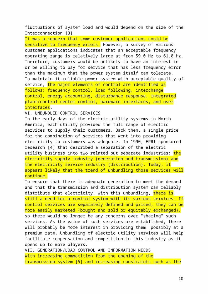
V. RELIABILITY, SECURITY, AND QUALITY OF SERVICENorth American utilities presently operate a highly reliable electric power system. Any and all future control concepts must not sacrifice the established level of reliability nor lead toward systems with unacceptable power outages and power shortages. The main objective and challenge will be enhancing the economy without sacrificing the security. There is a cost associated with controlling the frequency as tightly as it is controlled in North America. The technically necessary tightness of frequency control is required by power system equipment. For under-frequency, it is about 59.5 Hz, although some margin above 59.5 Hz would be needed to allow for random fluctuations of system load and would depend on the size of the Interconnection [3].It was a concern that some customer applications could be sensitive to frequency errors. However, a survey of various customer applications indicates that an acceptable frequency operating range is relatively large at from 59.0 Hz to 61.0 Hz. Therefore, customers would be unlikely to have an interest in or be willing to pay for service that has less frequency error than the maximum that the power system itself can tolerate.To maintain it reliable power system with acceptable quality of service, the major elements of control are identified as follows: frequency control, load following, interchange control, energy accounting, disturbance response, integrated plant/control center control, hardware interfaces, and user interfaces.VI. UNBUNDLED CONTROL SERVICESIn the early days of the electric utility systems in North America, each utility provided the full range of electric services to supply their customers. Back then, a single price for the combination of services that went into providing electricity to customers was adequate. In 1990, EPRI sponsored research [4] that described a separation of the electric utility business into two related but separate industries: the electricity supply industry (generation and transmission) and the electricity service industry (distribution). Today, it appears likely that the trend of unbundling those services will continue.To ensure that there is adequate generation to meet the demand and that the transmission and distribution system can reliably distribute that electricity, with this unbundling, there is still a need for a control system with its various services. If control services are separately defined and priced, they can be more easily marketed (bought and sold or equitably exchanged), so there would no longer be any concerns over "sharing" such services. As the value of such services are established, there will probably be more interest in providing them, possibly at a premium rate. Unbundling of electric utility services will help facilitate compensation and competition in this industry as it opens up to more players. VII. GENERATION/LOAD CONTROL AND INFORMATION NEEDS
6

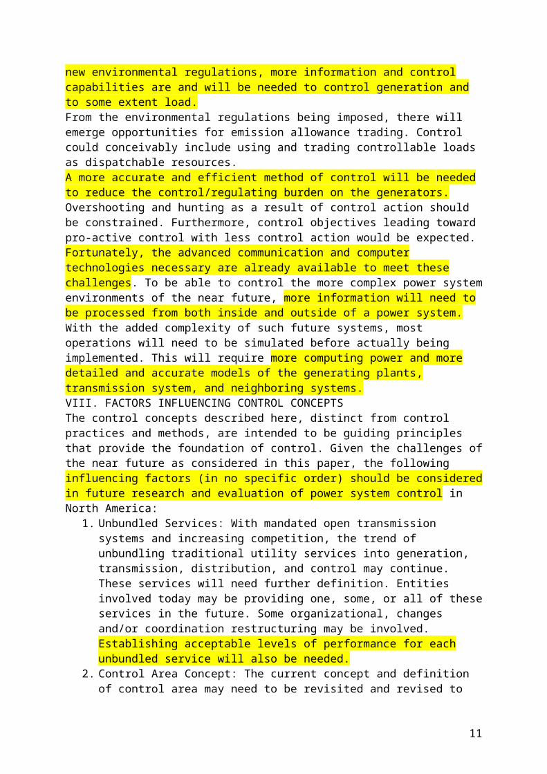
With increasing competition from the opening of the transmission system [5] and increasing constraints such as the new environmental regulations, more information and control capabilities are and will be needed to control generation and to some extent load.From the environmental regulations being imposed, there will emerge opportunities for emission allowance trading. Control could conceivably include using and trading controllable loads as dispatchable resources.A more accurate and efficient method of control will be needed to reduce the control/regulating burden on the generators. Overshooting and hunting as a result of control action should be constrained. Furthermore, control objectives leading toward pro-active control with less control action would be expected.Fortunately, the advanced communication and computer technologies necessary are already available to meet these challenges. To be able to control the more complex power system environments of the near future, more information will need to be processed from both inside and outside of a power system. With the added complexity of such future systems, most operations will need to be simulated before actually being implemented. This will require more computing power and more detailed and accurate models of the generating plants, transmission system, and neighboring systems.VIII. FACTORS INFLUENCING CONTROL CONCEPTSThe control concepts described here, distinct from control practices and methods, are intended to be guiding principles that provide the foundation of control. Given the challenges of the near future as considered in this paper, the following influencing factors (in no specific order) should be considered in future research and evaluation of power system control in North America:
1. Unbundled Services: With mandated open transmission systems and increasing competition, the trend of unbundling traditional utility services into generation, transmission, distribution, and control may continue. These services will need further definition. Entities involved today may be providing one, some, or all of these services in the future. Some organizational, changes and/or coordination restructuring may be involved. Establishing acceptable levels of performance for each unbundled service will also be needed.
2. Control Area Concept: The current concept and definition of control area may need to be revisited and revised to ensure that it can incorporate upcoming changes. These changes may be a result of a more open transmission system, increased penetration of non-utility generation, various forms of wheeling, and other competitive requirements, and/or the influences of environmental constraints.
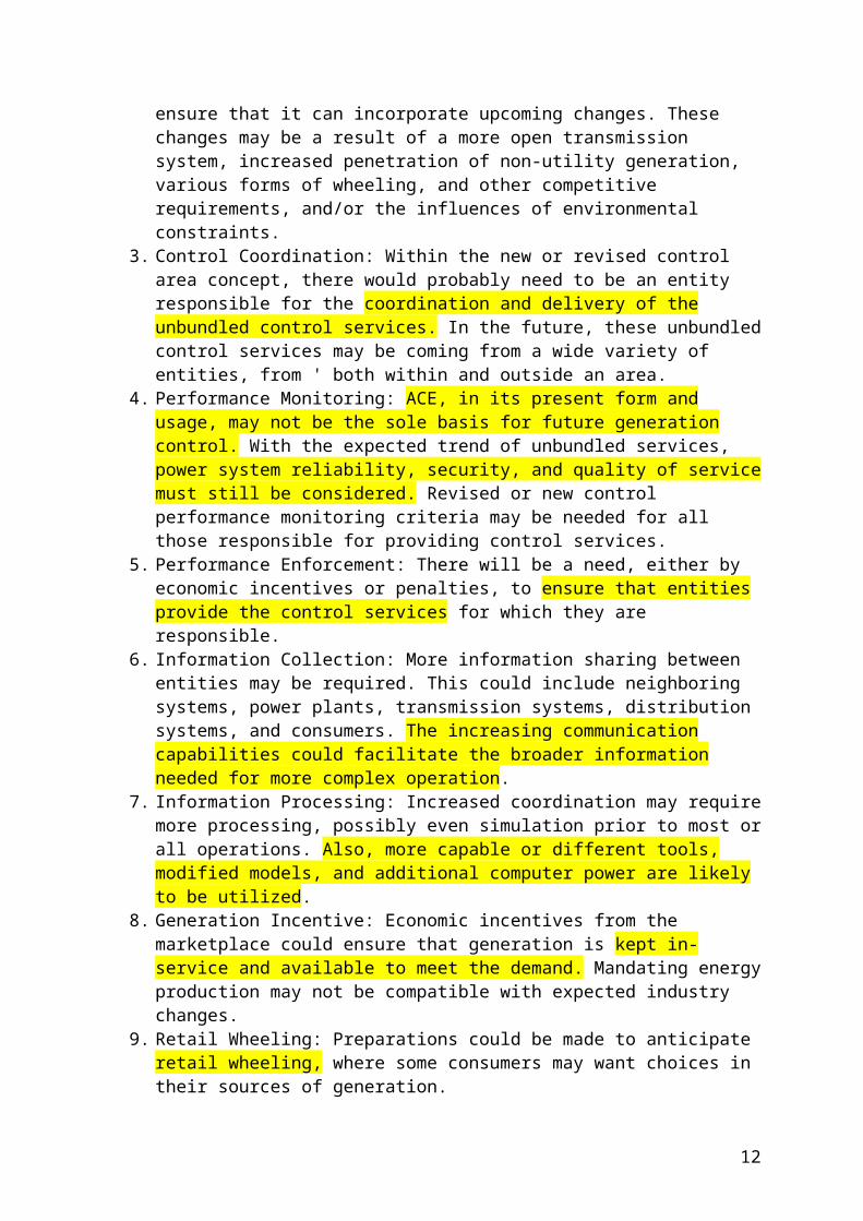
3. Control Coordination: Within the new or revised control area concept, there would probably need to be an entity responsible for the coordination and delivery of the unbundled control services. In the future, these unbundled control services may be coming from a wide variety of entities, from ' both within and outside an area.
4. Performance Monitoring: ACE, in its present form and usage, may not be the sole basis for future generation control. With the expected trend of unbundled services, power system reliability, security, and quality of service must still be considered. Revised or new control performance monitoring criteria may be needed for all those responsible for providing control services.
5. Performance Enforcement: There will be a need, either by economic incentives or penalties, to ensure that entities provide the control services for which they are responsible.
6. Information Collection: More information sharing between entities may be required. This could include neighboring systems, power plants, transmission systems,
7
distribution systems, and consumers. The increasing communication capabilities could facilitate the broader information needed for more complex operation.
7. Information Processing: Increased coordination may require more processing, possibly even simulation prior to most or all operations. Also, more capable or different tools, modified models, and additional computer power are likely to be utilized.
8. Generation Incentive: Economic incentives from the marketplace could ensure that generation is kept in-service and available to meet the demand. Mandating energy production may not be compatible with expected industry changes.
9. Retail Wheeling: Preparations could be made to anticipate retail wheeling, where some consumers may want choices in their sources of generation.
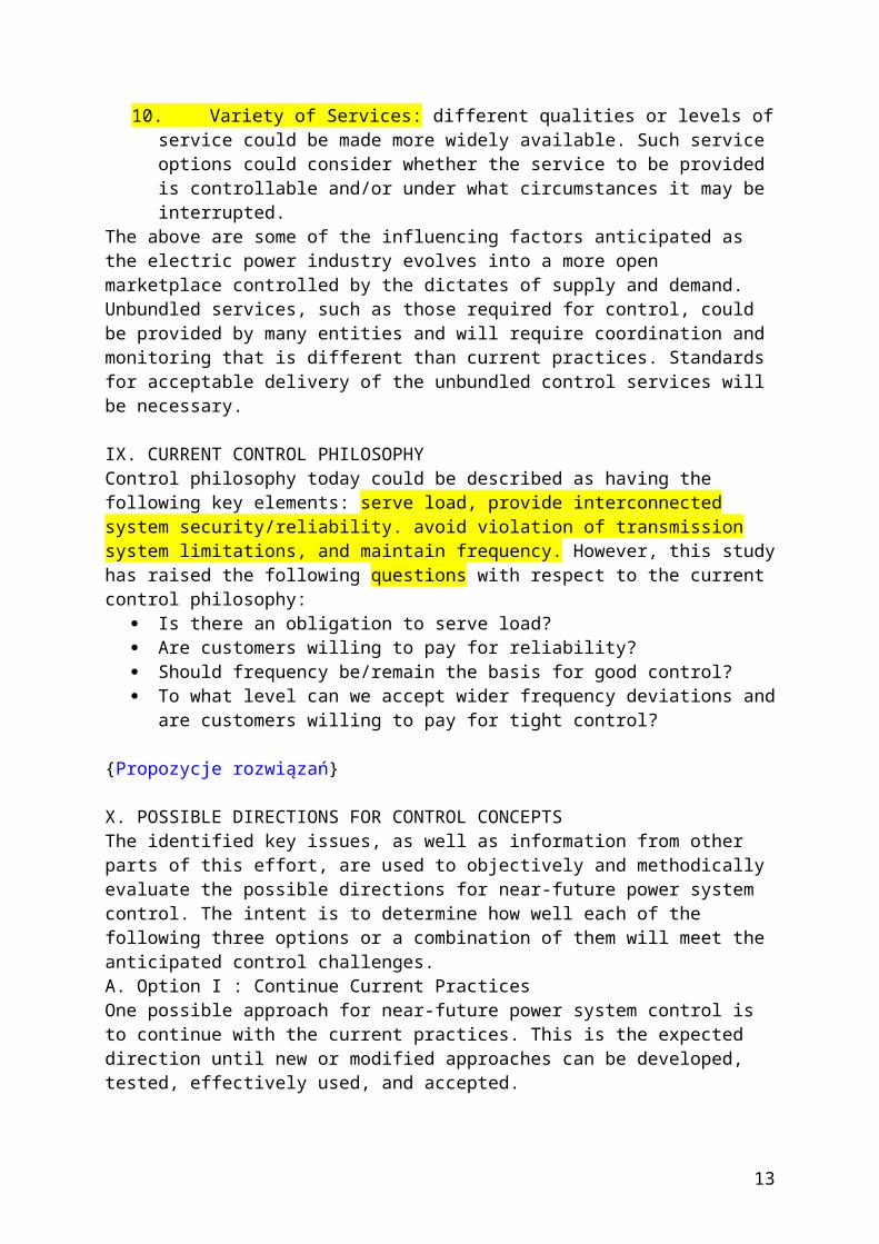
10. Variety of Services: different qualities or levels of service could be made more widely available. Such service options could consider whether the service to be provided is controllable and/or under what circumstances it may be interrupted.
The above are some of the influencing factors anticipated as the electric power industry evolves into a more open marketplace controlled by the dictates of supply and demand. Unbundled services, such as those required for control, could be provided by many entities and will require coordination and monitoring that is different than current practices. Standards for acceptable delivery of the unbundled control services will be necessary.
IX. CURRENT CONTROL PHILOSOPHYControl philosophy today could be described as having the following key elements: serve load, provide interconnected system security/reliability. avoid violation of transmission system limitations, and maintain frequency. However, this study has raised the following questions with respect to the current control philosophy:
Is there an obligation to serve load? Are customers willing to pay for reliability? Should frequency be/remain the basis for good control? To what level can we accept wider frequency deviations and are customers willing to
pay for tight control?
{Propozycje rozwiązań}
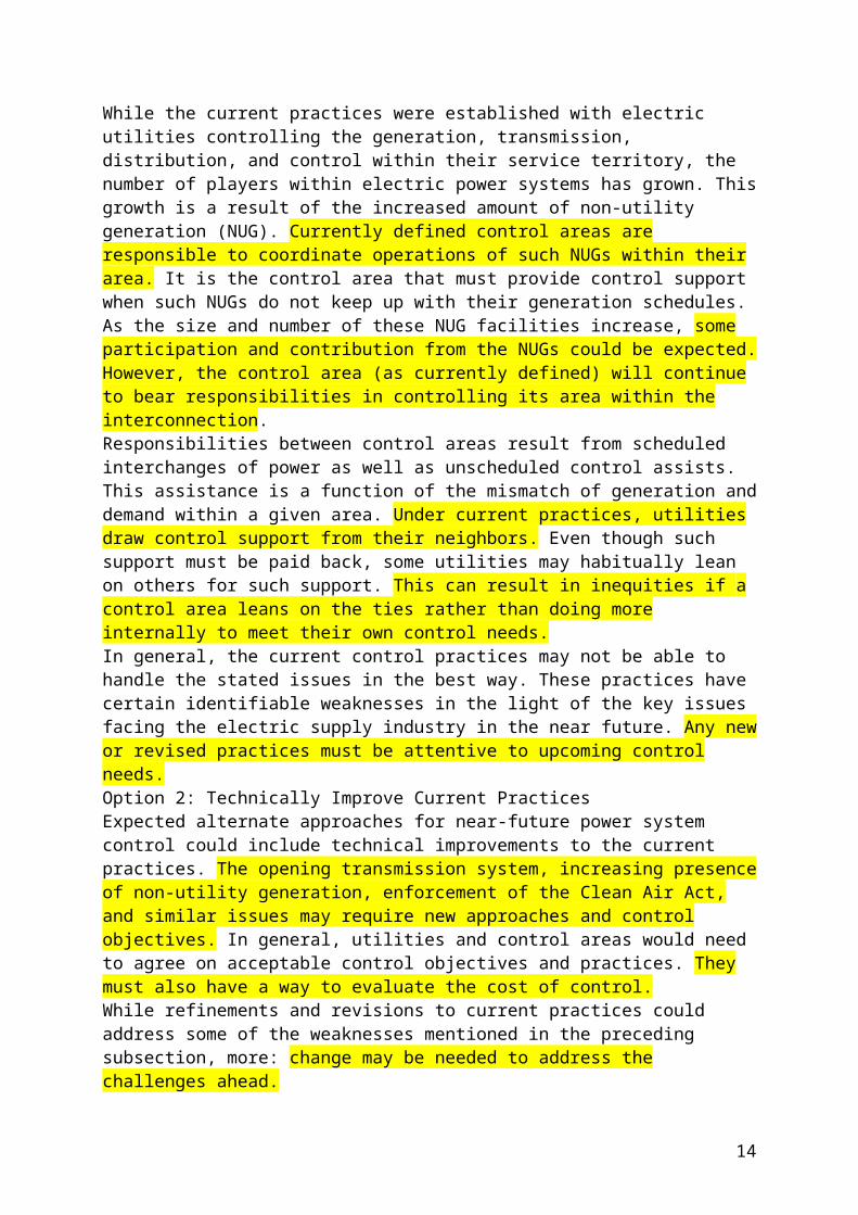
X. POSSIBLE DIRECTIONS FOR CONTROL CONCEPTSThe identified key issues, as well as information from other parts of this effort, are used to objectively and methodically evaluate the possible directions for near-future power system control. The intent is to determine how well each of the following three options or a combination of them will meet the anticipated control challenges.A. Option I : Continue Current PracticesOne possible approach for near-future power system control is to continue with the current practices. This is the expected direction until new or modified approaches can be developed, tested, effectively used, and accepted. While the current practices were established with electric utilities controlling the generation, transmission, distribution, and control within their service territory, the number of players within electric power systems has grown. This growth is a result of the increased amount of non-utility generation (NUG). Currently defined control areas are responsible to coordinate operations of such NUGs within their area. It is the control area that must provide control support when such NUGs do not keep up with their generation schedules. As the size and number of these NUG facilities increase, some participation and contribution from the NUGs could be expected. However, the control area (as currently defined) will continue to bear responsibilities in controlling its area within the interconnection.
8
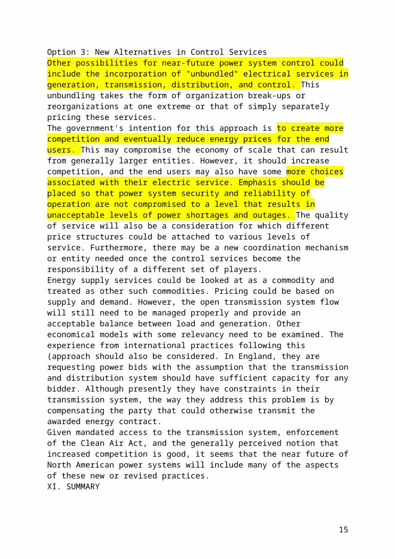
Responsibilities between control areas result from scheduled interchanges of power as well as unscheduled control assists. This assistance is a function of the mismatch of generation and demand within a given area. Under current practices, utilities draw control support from their neighbors. Even though such support must be paid back, some utilities may habitually lean on others for such support. This can result in inequities if a control area leans on the ties rather than doing more internally to meet their own control needs. In general, the current control practices may not be able to handle the stated issues in the best way. These practices have certain identifiable weaknesses in the light of the key issues facing the electric supply industry in the near future. Any new or revised practices must be attentive to upcoming control needs.Option 2: Technically Improve Current PracticesExpected alternate approaches for near-future power system control could include technical improvements to the current practices. The opening transmission system, increasing presence of non-utility generation, enforcement of the Clean Air Act, and similar issues may require new approaches and control objectives. In general, utilities and control areas would need to agree on acceptable control objectives and practices. They must also have a way to evaluate the cost of control.While refinements and revisions to current practices could address some of the weaknesses mentioned in the preceding subsection, more: change may be needed to address the challenges ahead.Option 3: New Alternatives in Control ServicesOther possibilities for near-future power system control could include the incorporation of "unbundled" electrical services in generation, transmission, distribution, and control. This unbundling takes the form of organization break-ups or reorganizations at one extreme or that of simply separately pricing these services.The government's intention for this approach is to create more competition and eventually reduce energy prices for the end users. This may compromise the economy of scale that can result from generally larger entities. However, it should increase competition, and the end users may also have some more choices associated with their electric service. Emphasis should be placed so that power system security and reliability of operation are not compromised to a level that results in unacceptable levels of power shortages and outages. The quality of service will also be a consideration for which different price structures could be attached to various levels of service. Furthermore, there may be a new coordination mechanism or entity needed once the control services become the responsibility of a different set of players.Energy supply services could be looked at as a commodity and treated as other such commodities. Pricing could be based on supply and demand. However, the open transmission system flow will still need to be managed properly and provide an acceptable balance between load and generation. Other economical models with some relevancy need to be examined. The experience from international practices following this (approach should also be considered. In England, they are requesting power bids with the assumption that the transmission and distribution system should have sufficient capacity for any bidder. Although presently they have constraints in their transmission system, the way they address this problem is by compensating the party that could otherwise transmit the awarded energy contract.Given mandated access to the transmission system, enforcement of the Clean Air Act, and the generally perceived notion that increased competition is good, it seems that the near future of North American power systems will include many of the aspects of these new or revised practices. XI. SUMMARY
9
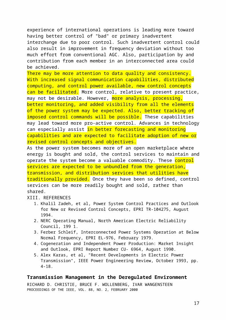
There are major changes happening in the electric supply industry. The Federal government has mandated environmental constraints. The government is fostering competition with the expectation that it will result in more economical energy for consumers and, in the long term, improve the quality of service. It is also anticipated that consumers will eventually have a choice in selecting their energy supplier(s). As a result, changes are expected to which electric utilities need to adapt. Undoubtedly, these changes will influence power system control practices and may demand new or revised control objectives. It is expected that current practices will continue to evolve as revised or new approaches are established. Obviously, it is advantageous to those in the electric supply industry to forecast the expected control practices and make preparations for a smooth transition to them.In the process of these changes, economics will probably be the most influential factor in meeting environmental constraints. It is emphasized throughout this paper that reliability, security, and quality of service cannot be compromised. Otherwise, the expected economic gain in the long term may not materialize, and the initial justifications for that economic gain may be discredited.An open transmission system will introduce complications. Theoretically, unlimited capacity on the transmission/ distribution system is needed to truly accomplish the open system principle. Since the existing transmission/distribution systems are constrained in their capacity in at least certain areas and conditions, open access to all the parties all the time may not be possible. Therefore under certain conditions, access for some parties will be denied. A practical implementation of an open transmission system will eventually be achieved. As an interim solution, the practice being utilized in England may be considered, where the parties that get excluded from access to the transmission/distribution system are being compensated. The open transmission system and participation of non-utility generation may allow better management of the environmental constraints.The necessity and tightness of frequency control is being questioned and could be challenged further as the expected changes are taking effect. There will be challenges in establishing new control objectives based on conventional frequency deviations or other possible approaches. The experience of international operations is leading more toward having better control of "bad" or primary inadvertent interchange due to poor control. Such inadvertent control could also result in improvement in frequency deviation without too much effort from conventional AGC. Also, participation by and contribution from each member in an interconnected area could be achieved.There may be more attention to data quality and consistency. With increased signal communication capabilities, distributed computing, and control power available, new control concepts can be facilitated. More control, relative to present practice, may not be desirable. However, more analysis, processing, better monitoring, and added visibility from all the elements of the power system may be expected. Also, better tracking of imposed control commands will be possible. These capabilities may lead toward more pro-active control. Advances in technology can especially assist in better forecasting and monitoring capabilities and are expected to facilitate adoption of new or revised control concepts and objectives.As the power system becomes more of an open marketplace where energy is bought and sold, the control services to maintain and operate the system become a valuable commodity. These control services are expected to be unbundled from the generation, transmission, and distribution services that utilities have traditionally provided. Once they have been so defined, control services can be more readily bought and sold, rather than shared.XIII. REFERENCES
1. Khalil Zadeh, et al, Power System Control Practices and Outlook for New or Revised Control Concepts, EPRI TR-104275, August 1994.
2. NERC Operating Manual, North American Electric Reliability Council, 199 1.
10
3. Ferber Schleif, Interconnected Power Systems Operation at Below Normal Frequency, EPRI EL-976, February 1979.
4. Cogeneration and Independent Power Production: Market Insight and Outlook, EPRI Report Number CU- 6964, August 1990.
5. Alex Karas, et al, "Recent Developments in Electric Power Transmission", IEEE Power Engineering Review, October 1993, pp. 4-18.
Transmission Management in the Deregulated EnvironmentRICHARD D. CHRISTIE, BRUCE F. WOLLENBERG, IVAR WANGENSTEENPROCEEDINGS OF THE IEEE, VOL. 88, NO. 2, FEBRUARY 2000
{Problem zarządzania przepływami mocy w warunkach rynku – OPF (podstawy matematyczne) – zarządzanie przesyłem – zarządzanie ograniczeniami przesyłu (ang. congestion management) – Analiza rozpływów mocy}
Coordination of Power Flow Control in Large Power SystemsFan Li, Baohua Li, and Xujun ZhengIEEE TRANSACTIONS ON POWER SYSTEMS, VOL. 16, NO. 4, NOVEMBER 2001
Boosting Immunity to Blackouts,
Stanley H. Horowitz, Arun G. PhadkeIEEE power & energy magazine, september/october 2003
{Odporność na black-outy - Zabezpieczenia przyszłości}
CATASTROPHIC FAILURES OF ELECTRIC POWER SYSTEMS HAVE BEEN OCCURRING WITH some regularity throughout the history of interconnected electric power grids. In recent years there seems to be an increase in their frequency and severity, perhaps due to the confusing and complex environment brought about by deregulation of the industry. At the same time, the hardship and economic penalties associated with such events have become ever more important as society comes to depend heavily on the availability of high-quality power supply. It is recognized that complete immunity from such catastrophic failures—blackouts—is not possible to achieve. However, there have been several key developments in recent years that make it conceivable that it would soon be possible to reduce the frequency and intensity of such failures. System protection is one of the technologies undergoing radical changes that holds a strong promise that cascading system outages can be mitigated or even eliminated. The increasing use of digital relays that will allow the implementation of exciting new concepts has made this a strong possibility. To further examine these possibilities, a conference was held in Beijing, China, 23-27 September 2003 under the auspices of the International Institute for Critical Infrastructure (CRIS). The subjects included future concepts in power system protection, communication, wide area measurement systems (WAMS), system control, and electricity market considerations. In this article, we will report on some of the ideas discussed at the conference, adding a summary of our own research in associated studies and our assessment of future investigations. Our aim is to provide a blueprint for a secure power system infrastructure. Our discussion will include improvements in system protection through adaptive relaying including hidden failures and associated ideas, the role of communication, and the redesign of the system from an inflexible network to one that is more ductile.
11
Evolutions in Real-Time Tools for Improved Power System OperationsIt is important to recognize that the built-in strength of the power system is the best defense against catastrophic failures. However, due to economic, environmental, and regulatory constraints, a system may not possess an optimal configuration, and at any given instant it may not be operating in its most robust state. For a given configuration of the system, it is the performance of protection, monitoring, and control equipment that will determine how a system would respond to catastrophic events and other contingencies. There have been very significant developments in the fields of protection, monitoring, and control that are expected to alter the ways in which the power systems of the future will respond to contingencies. These developments are reviewed in this section.ProtectionComputer relaying started a major revolution in this field, and the era of advanced protection concepts was inaugurated through the ability of relays to communicate with remote sites. The first among these is the field of adaptive relaying. The fundamental ideas of adaptive relaying have been described in previous articles and technical papers. Although these concepts have been discussed in fundamental terms, we would now like to reexamine some of the features in more detail.Adaptive RelayingThe concept of adaptive relaying is that many relay settings are dependent upon assumed conditions on the power system. In order to cover all possible scenarios that the protection system may have to face, the actual protection settings in use are often not optimal for any particular system state. If an optimal setting is desired for an existing condition on the power network, then it becomes necessary for the setting to adapt itself to the real-time system states as the system conditions change. Many examples of adaptive relaying ideas have been mentioned in the literature. Perhaps the most striking example -- which also illustrates the strength of the concept nicely - is the concept of adaptive dependability-security balance.When the power system is in a normal (healthy) state, there is sufficient generation and spinning reserve to meet the connected load, and transmission facilities are robust enough to provide strong alternative paths for power flow in the event of contingencies. In such a state, the greatest danger to the power system is instability resulting from faults that are not cleared quickly. It is therefore normal practice to design the protection system with a very high level of dependability, thereby making sure that all faults will be cleared by primary protection systems. The penalty for making the system highly dependable is a loss of security: the protection system may operate unnecessarily, removing system components that were not faulted. Such over-tripping is not harmful for a robust power system. However, when the power system is not robust because of prevailing stressful conditions, the bias toward dependability is harmful. Then the system can ill afford to lose an unfaulted transmission facility in error. One would now prefer to have a protection system that is biased in favor of security. Thus, one would reduce risk of false trips and accept a reduction in dependability.
12
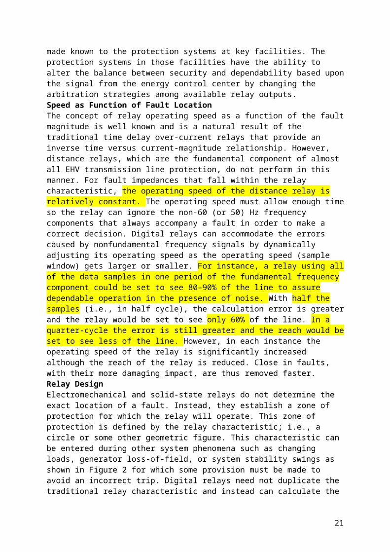
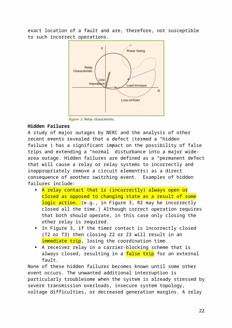
A very powerful adaptive relaying concept helps realize this flexible dependability-security balance as shown in Figure 1. Based upon an assessment of the condition of the network made at the energy control center of the power system, a decision is made as to whether the power system is in a normal healthy state or in a stressed state. This state characterization is made known to the protection systems at key facilities. The protection systems in those facilities have the ability to alter the balance between security and dependability based upon the signal from the energy control center by changing the arbitration strategies among available relay outputs.Speed as Function of Fault LocationThe concept of relay operating speed as a function of the fault magnitude is well known and is a natural result of the traditional time delay over-current relays that provide an inverse time versus current-magnitude relationship. However, distance relays, which are the fundamental component of almost all EHV transmission line protection, do not perform in this manner. For fault impedances that fall within the relay characteristic, the operating speed of the distance relay is relatively constant. The operating speed must allow enough time so the relay can ignore the non-60 (or 50) Hz frequency components that always accompany a fault in order to make a correct decision. Digital relays can accommodate the errors caused by nonfundamental frequency signals by dynamically adjusting its operating speed as the operating speed (sample window) gets larger or smaller. For instance, a relay using all of the data samples in one period of the fundamental frequency component could be set to see 80–90% of the line to assure dependable operation in the presence of noise. With half the samples (i.e., in half cycle), the calculation error is greater and the relay would be set to see only 60% of the line. In a quarter-cycle the error is still greater and the reach would be set to see less of the line. However, in each instance the operating speed of the relay is significantly increased although the reach of the relay is reduced. Close in faults, with their more damaging impact, are thus removed faster.Relay DesignElectromechanical and solid-state relays do not determine the exact location of a fault. Instead, they establish a zone of protection for which the relay will operate. This zone of protection is defined by the relay characteristic; i.e., a circle or some other geometric figure. This characteristic can be entered during other system phenomena such as changing loads, generator loss-of-field, or system stability swings as shown in Figure 2 for which some provision must be made to avoid an incorrect trip. Digital relays need not duplicate the traditional relay characteristic and instead can calculate the exact location of a fault and are, therefore, not susceptible to such incorrect operations.
13
Hidden FailuresA study of major outages by NERC and the analysis of other recent events revealed that a defect (termed a “hidden failure”) has a significant impact on the possibility of false trips and extending a “normal” disturbance into a major wide-area outage. Hidden failures are defined as a “permanent defect that will cause a relay or relay systems to incorrectly and inappropriately remove a circuit element(s) as a direct consequence of another switching event.” Examples of hidden failures include:
A relay contact that is (incorrectly) always open or closed as opposed to changing state as a result of some logic action. (e.g., in Figure 3, R2 may be incorrectly closed all the time.) Although correct operation requires that both should operate, in this case only closing the other relay is required.
In Figure 3, if the timer contact is incorrectly closed (T2 or T3) then closing Z2 or Z3 will result in an immediate trip, losing the coordination time.
A receiver relay in a carrier-blocking scheme that is always closed, resulting in a false trip for an external fault.
None of these hidden failures becomes known until some other event occurs. The unwanted additional interruption is particularly troublesome when the system is already stressed by severe transmission overloads, insecure system topology, voltage difficulties, or decreased generation margins. A relay malfunction that would immediately cause a trip such as Z1 in Figure 3 is not a hidden failure.
14
Regions of VulnerabilityThe existence of a hidden failure does not by itself always result in the incorrect and undesirable operation contributing to the disturbance degradation. There is also a component that consists of a physical region in the network such that a given relay with a hidden failure would not operate incorrectly for faults in that region. It is the combination of the hidden failure and a fault in the region of vulnerability that results in extending the area outage. A step distance relay scheme with Zone 1 and Zone 2 reach settings is shown in Figure 4. Zone 1 operates instantaneously for a fault within its setting, and Zone 2 operates after a given time. Assuming the timer contact is incorrectly closed all the time, a fault F1 within the zone 2 setting would trip incorrectly without time delay. However, a fault at F2 would not be seen by the Zone 2 relay, so, even with the hidden failure of the timer, no trip would occur. Thus, there is a region of vulnerability (the dark area) for which hidden failures may cause incorrect and undesirable trips but beyond which they would have no effect.
Accepting the fact that system stress, outage analysis, hidden failures, and regions of vulnerability define the potential for an insecure power system infrastructure, we need to design and implement countermeasures against cascading. The solution that immediately presented itself when digital relays were first being considered was the fact that digital relays have the capability of self-checking. The relay could then advise a central office or implement some corrective action within itself or from other digital devices. Later it became obvious that the relay could adapt to changing system conditions by changing characteristics or settings using the appropriate system and fault logic and the logic within the digital device itself.
Below are some examples of other relaying problems and possible counter-measures.1) Adaptive control of defective relays. This was the first advantage recognized for digital relays. The relay can monitor itself and give immediate alarm that a correction is needed.2) Load effect. One of the most significant causes of incorrect distance relay tripping is the fact that the relay characteristic under severe system conditions can be encroached upon by heavy loads. The solution is to monitor the load and eliminate it from the digital relay fault-processing algorithm.3) Cold load pickup. The restoration of load, particularly on distribution circuits, results in current magnitudes that exceed the normal instantaneous relay settings. Logic can be
15

employed to recognize the length of an outage and the magnitude of the load pickup current. Today’s solution is to remove the instantaneous relay for a period of time after the circuit is restored. Digital relays can have their setting automatically adjusted to maintain protection.4) End-of-line protection. Instantaneous relays must not overreach a line to avoid loss of coordination. Recognizing that the remote breaker has opened and transmitting this fact to the other end allows the instantaneous relay setting to be adjusted for this stub fault, protecting the entire line instantaneously rather than relying on a time-delay over-current relay.5) Multiterminal line protection. Traditional setting philosophy requires that Zone 1 must underreach the remote terminal to avoid loss of coordination and is therefore set with no in-feed. Zones 2 and 3 must overreach to insure 100% line protection and are set with in-feed. Transmitting the status of either the breakers or the actual current to all terminals allows the setting to avoid potentially damaging compromises.6) Transformer protection. Aside from the problem of harmonics, transformer differential relays must accommodate tap changes, CT ratio mismatch, and other errors. Adaptive relays can monitor the actual currents and adjust the percentage setting for them.
MonitoringThe use of real-time measurements to determine the state of the power system goes back to the late 1960s. State estimation, contingency evaluations, and optimization of the operating state have been practiced by most modern power systems. The nature of the real-time data available for these functions meant that the monitoring functions had to be restricted to steady-state phenomena. However, the constraining contingencies for power systems are usually rooted in the dynamic phenomena. Thus, there has been a disconnect between what is actually needed in real-time monitoring and what could be achieved by the prevailing technology.All of this is about to change. The technological revolution brought about by computer-based measurements of power quantities and the capability provided by GPS transmissions to synchronize measurements to within a microsecond has made truly simultaneous system measurements a reality. With the capability for high-speed broadband communication provided by modern fiber-optic networks, it is now within the grasp of the power system operators to achieve real-time dynamic monitoring and contingency evaluation and to devise counter-measures against impending catastrophic events. This new synchronized phasor measurement technology is the key element of the emerging WAMS that are being installed on a trial basis by many electric power systems around the world. As the analytical techniques for effectively using these measurements in real-time become mature, a new era in power system monitoring will emerge.ControlThe WAMS discussed above have also been tapped to see if they can be profitably used for improving several control functions. Various studies on using these real-time measurements as feedback signals for controlling HVDC systems, power system stabilizers, and static VAR systems have appeared in the literature. The basic concept of phasor measurements for feedback is shown in Figure 5. The figure shows a representation of a large power system, which contains a controllable device that would influence wide-area behavior of the power system following a catastrophic event. Until the real-time synchronized measurements were available, the only way to use the controller was to provide it with a locally generated feedback signal and describe the relationship between what can be measured locally and what needs to be controlled on the power system. This requires assumptions about the power system model, and one could term controllers of this type as model-based controllers.To the extent that the mathematical models used in the feedback process were approximations, such model-based controllers were also an approximation to the optimal
16
controllers. As is well known, most large-scale disturbances on power networks are nonlinear in nature, and all model-based controllers tend to be quite approximate in the presence of really large (catastrophic) disturbances.As shown in Figure 5, the controller that is designed to control certain system responses (for example, phase angle across large segments of the system, frequency excursions, un-damped oscillations, etc.) would use the actual measured quantity at the locations where the control is to be exercised. These measurements are generated with response times on the order of one cycle and can be communicated to remote locations within a few cycles. Considering that most power system dynamic phenomena demonstrate periods on the order of a second, these measurements are essentially real-time measurements.Studies of controllers based upon remote measurement feedback systems have been reported in the literature and show the advantage of using measurement feedback over model-based feedback systems. As the above discussion shows, the infrastructures of power supply, computer networks, and communication systems are being fused into a unified structure, and the ability of any one infrastructure to respond to catastrophic events is going to depend upon the success of integration of these critical infrastructures.Critical InfrastructuresCertain infrastructures are critical for the well being of a modern society. Electric power, communications, computer, transportation, and logistics are examples of critical infrastructures. Correlation between the health of these infrastructures and the security and prosperity of nations has been well demonstrated in many economic and sociological studies.In recent years, these infrastructures have become integrated to a very large extent, leading to a new super-infrastructure with different structures obeying their own physical laws superimposed on each other and interacting with each other in a very intimate manner at critical operational levels. An example of such a super-infrastructure is the integrated power, communication and computer (PCC) infrastructure. It is essential to treat these new entities as systems requiring their own underlying theoretical foundation. To develop and understand a formal systems theory of interacting infrastructures (PCC) from the point of view of reliability, their modes of failure, their resistance to catastrophic failures, and countermeasures to prevent catastrophic failures caused by technical, manmade, or natural causes is an important topic of current research in power system engineering.In the earlier sections of this article we discussed the evolution of new operational tools for power systems such as advanced protection, monitoring, and control. One should also recognize the importance of introducing newer types of devices in power systems that would make them robust in the face of catastrophic failures. Many high-power electronic devices such as HVDC links and static VAR compensators are already being used for this purpose. In the abstract, these devices can be viewed as modifying the nature of the power system from being brittle to being more ductile.Brittle and Ductile InfrastructuresModern power systems deliver power to the load centers efficiently and economically. However, they do have the tendency to break up through loss of synchronization when faced with a catastrophic disturbance. The break-up of a power system is similar to the shattering of a brittle structure upon being struck with a heavy blow. A ductile structure, on the other hand, would deform around the disturbance and prevent the disturbance from cascading. What would make a power system more ductile in the face of catastrophic events, and what would be the penalty for making such a transition?Increasing the ductile property of a structure is clearly going to require additional structural elements with specialized properties, requiring additional capital outlays. In the case of power systems, such elements must include HVDC links and other controllable high-power devices such as power system stabilizers, static and controllable series and shunt reactive elements,
17

dynamic brakes, etc. All of these devices now exist in small numbers on many power systems. However, they have been placed on an ad hoc basis, meeting some specific requirements at a local level. Making the entire system more ductile will require a full-scale investigation as to the placement of such elements and their desired dynamic properties. There may be need for entirely new types of elements that will have to be developed.
Two types of elements that are needed are those that will become active in the face of evolving catastrophic events: elements that automatically confine the disturbance to a small region (one could give them the generic name “Partitioners – P” for such devices) and devices that damp power swings as they occur (generic name “Dampers – D”). Such elements will remain dormant when the system is in a normal state, thus maintaining the efficiency and economy of operation. However, upon detecting the onset of a major disturbance, these devices (strategically placed on the system) would become active and limit the damage to a small region, leaving the rest of the system functioning normally. The detection of an evolving major event is clearly a newer type of relaying function performed at a system control-center level. The control center would then send commands to the “Partitioners” and “Dampers” to become active at appropriate locations. Highly sophisticated analytical techniques would have to be implemented at the control center in order to achieve these relaying capabilities. Also needed would be an extensive monitoring system supplemented by a communication network for gathering the information as well as for communicating the control commands to these devices. Figure 6 is an illustration of this concept. The figure shows that the special devices have been installed at critical points on the power system as determined by placement studies. P = the Partitioners and D = the Dampers. The control center would determine, based upon the monitoring data, which devices need to be activated in order to confine the disturbance to a small region and eliminate the possibility of cascading.ConclusionsThere is a fusion taking place of three critical infrastructures: power, communication, and computers. The development of new protection, monitoring, and control techniques that make use of new capabilities offers for the first time the opportunity to improve the performance of these infrastructures in the face of catastrophic events. It is recognized that no power system can be made completely immune to blackouts. However, with careful theoretical development of such super-infrastructures, it would be possible to make future power systems less susceptible to catastrophic failures. The coming years are going to offer exciting challenges and opportunities to make such systems a reality.For Further Reading
1. S.H. Horowitz, A.G. Phadke, and J.S. Thorp, “Adaptive transmission system relaying,” IEEE Trans. Power Delivery, vol. 3, no. 4, pp. 1436–1445, Oct. 1988.
2. S. Tamronglak. S. H. Horowitz, A.G. Phadke, and J.S. Thorp, “Anatomy of power system blackouts: Preventive relaying strategies,” IEEE Trans. Power Delivery, vol.
18

11, no. 2, pp. 708–715, Apr. 1996. (Received IEEE-Power System Relaying Committee Prize Paper Award.)
3. David C. Elizondo, J. De La Ree, Stan Horowitz, and A.G. Phadke, “Hidden failures in protection systems and its impact over wide-area disturbances,” presented at IEEE PES Winter Power Meeting, Columbus, Ohio, Jan. 28–Feb. 1, 2001.
4. A.G. Phadke, J.S. Thorp, and K. Karimi, “State estimation with phasor measurements,” IEEE Trans. Power Systems, pp. 233–241, Feb. 1986.
5. A.G. Phadke et al., “Synchronized sampling and phasor measurements for relaying and control,” presented at the IEEE PES Winter Power Meeting, Columbus, Ohio, Jan. 31 – Feb. 5, 1993, Paper No. 93WM 039-8 PWRD.
6. L. Mili, T. Baldwin, and A.G. Phadke, “Phasor measurements for voltage and transient stability monitoring and control,” presented at Workshop on Applications of Advanced Mathematics to Power Systems, San Francisco, CA, Sept. 4- 6, 1991.
{Ważny artykuł }
Preventing Future Blackouts by Means of Enhanced Electric Power Systems Control: From Complexity to OrderMARIJA D. ILIC´ , ERIC H. ALLEN, JEFFREY W. CHAPMAN, CHARLES A. KING, JEFFREY H. LANG, AND EUGENE LITVINOVPROCEEDINGS OF THE IEEE, VOL. 93, NO. 11, NOVEMBER 2005
I. INTRODUCTIONThis paper addresses difficult questions concerning the degree to which managing future electric power generation, delivery and consumption should and could rely on automatic control. In order to integrate power system monitoring and control tools effectively over a broad range of temporal and spatial horizons and for large deviations from nominal operation, we first re-visit the structure of the interconnection dynamics in the context of the nonstandard control problems of interest. The control of modern power systems can be analyzed as having open-loop response components, as well as components equipped with a variety of feedbacks. Feedback actions are either automated, or initiated by a human operator. Many of the feedback actions are in response to discrete events occurring at unplanned, asynchronous times and referred to as system contingencies.Typical system and control design has the objective of keeping the system within the stable and secure operating limits for any anticipated single contingency. The asynchronous discrete events also include relay actions, which generally disconnect pieces of equipment when acceptable state or control limits are exceeded. Therefore, any control design which takes into consideration control, state and/or output limits would automatically include relay actions. Some of the feedback actions are discrete both in time and in value, while the others are continuous. The resulting closed-loop hybrid (continuous and discrete) dynamics are very complex, and, are generally described by a set of coupled ordinary-differential equations (ODEs) (capturing continuous processes), discrete-time equations (DEs) (for discrete processes), and algebraic constraints for defining network system constraints.
19

To manage this huge complexity, an approach is suggested in this paper by which qualitative indices (QIs) could define type of operating mode the system is in, and could define corresponding multiple levels of abstraction and precision in the qualitative and quantitative organization of the closed-loop system response. An integrated multimodal approach recognizes different phenomena evolving on the system, and provides the minimum critical knowledge to those controllers whose logic has to be changed in order to effectively act as conditions change. The property of closed-loop monotone dynamic systems is suggested as the key property for justifying temporal and spatial separation of complex electric power system dynamics underlying their hierarchical control. As the conditions depart significantly from the nominal, this is reflected in the monitored QIs approaching abnormality and this is further used to indicate how controllers should change their logic so the closed-loop dynamics with the adjusted logic remain monotone, and, therefore, stabilizable. We discuss these concepts for both discrete and continuous controllers.First, an equivalenced Northeast Power Coordinating Council (NPCC) 38-bus system is used to illustrate performance of the system with current controllers in place. Next the potential of enhanced, multilayered control is illustrated in the same system. Potential benefits for both enhanced reliability during contingencies and for efficient use of resources during normal conditions are described.…{Opis black-out w US w roku 2003 a dalej}
The simplicity comes from the ability to decompose one very complex problem into several simpler subproblems, with respect to both time and network size. However, we recognize in this paper that current operating practices are limited in their ability to ensure acceptable performance over a very broad range of varying conditions. Today’s practices rely primarily on manual coordination between control areas with the NERC voluntary guidelines being the only backstop to ensure consistency and compliance. The events of August 2003 underscore the shortcomings of voluntary guidelines in a market oriented environment.We suggest in this paper the consideration of an alternative more adaptive approach. Namely, as the loading conditions and equipment status vary, it becomes necessary to monitor these changes and to reschedule the available resources to best meet the new conditions. In addition, it is essential to adjust to hard-to-predict changes, small and large, fast and slow. Doing this on-line presents a major challenge to system monitoring and control. During normal conditions this approach would require monitoring and data processing into a valuable information to be used by the on-line decision tools. The minimal slow communications between different parts of the system generally suffices in normal operations and it is currently used for decentralized optimization of the available resources. The challenge is much more severe during major emergencies when effective coordination of system-wide reserve allocation is needed for preserving the system-wide integrity.It is illustrated in Section VII what can the system manage with and without such coordination. An a priori decomposition of the operating and
20
control problem into subtasks commonly used for methods in support of normal operation may no longer hold. This requires then an on-line detection of the type of condition mode the system is in, and adaptive adjustments of control logic over all time horizons and electrical distances. In this paper, we consider possible systematic enhancements of current operating practices by means of on-line feed-forward decision making and feedback control to ensure acceptable service over a wide range of supply–demand patterns and equipment status. In this paper, we attempt to provide a somewhat self-contained treatment of a typical blackout, its dynamics and dependence on control and to explain what might be essential to enhance in the future control of electric power systems.For example, a very large system may have enough stored kinetic energy in the moving rotors of all the generators connected to the network, so that when the fault takes place, the energy loss caused by losing the faulted piece of equipment gets compensated by the energy from other generators. The system may settle to a new equilibrium even without re-connecting the faulted equipment. To the contrary, if the system is pushed to the limits of its stability, the system stability may be completely lost. Deciding on when this occurs and how to prevent it from happening is the main objective of reliable operations for modern day electric power systems.It is illustrated later in this paper that both the choice of control logic on generator controllers and adjusting their set points as the events unfold may make a qualitative difference between fault being transiently stable or unstable. If the logic of these controllers is tuned for different operating modes accordingly, then keeping the system intact during faults becomes a much less challenging task. As the power flow patterns vary and the equipment status changes, the control objectives and the logic of these controllers must be adjusted adequately for predictable performance.
{korzystanie z nowych technologii sterowania FACTS, nowe rodzaje PSS itp. }
B. Automation Needs for Managing System Efficiently by Means of Novel TechnologiesWhile the challenge to reliably operating complex electric power systems of the future is clearly supported by the need to prevent wide-spread blackouts in the future, the needs for enhancing their overall automation for quantifiable performance is also related to the industry restructuring and also to the ability to implement fast power electronic switched hardware. There are at least three major additional reasons.First, existing transmission systems are being operated under loading conditions that challenge the capability of existing control systems. This is a result of changing environmental and economic demands on the power industry coupled with the difficulty and expense of providing new transmission capacity in response to the expansion and geographic redistribution of load. Second, the availability of flexible ac transmission system (FACTS) components such as static VAR compensators and thyristor-controlled series capacitors is creating opportunities for a redefinition of the transmission grid from an essentially passive system
21
component to an active element that will play a major role in the operation of the power industry [6], [7]. These devices are capable of responding to system transients over a time scale of fractions of a second, making them suitable for controlling the short-term system response following system upsets such as equipment failures, short circuits and the like. In addition, the use of microprocessor-based control as an enhancement to established devices such as power system stabilizers (PSSs) has created the potential for higher performance control through the application of nonlinear control techniques such as variable structure control, feedback linearization, adaptive control and various paradigms currently lumped under the name of “intelligent” control. Third, recent breakthroughs in fast and inexpensive measurement and communications offer previously un-imaginable opportunities for monitoring and controlling events in timely manner over a vast area such as the US electric power interconnection. This includes on-line monitoring and communications with the end users for adaptive use of available supply.
{Nowe założenia dotyczące teorii niezawodności SEE – potrzeba nowych wskaźników itp. – nie tylko ustalenie przedziałów tolerancji częstotliwości i napięcia lecz także „This also must be done within the safety limits for all equipment. Moreover, everything is to be performed at the reasonable costs – więcej na ten temat jest w załacznikach tego artykułu” }
{I tutaj autorzy zaproponowali pewne działania do zrobienia od strony odbiorcy}
This problem, of course, does not always lend itself to a feasible solution for given system resources. Because of this, at the design stage one must establish requirements for sufficient control capacity needed to meet the above specifications. If adding a new controller is economically unacceptable, then control actions such as relaxing performance specifications on the customers’ side must be considered. In this case, un-popular control actions such as partial load shedding are part of the required reliability framework. Historically, power systems have been designed in a sufficiently redundant manner so that the reliable service was not critically dependent on just-in-time decision/control actions. Decisions and control actions have primarily been for efficient scheduling of resources to compensate for hourly disturbances during normal operations assuming no dynamic problems as long as local constant-gain controllers are correcting for presumably small deviations.During unplanned equipment failures reserves were used to ensure uninterrupted service.{Potrzeba nowych wskaźników o stanach nienormalnych SEE}
A. Need for Indicators of Abnormal ConditionsIn this paper, we point out that if the system is operated for whatever reasons over very broad ranges of conditions, it is practically impossible to differentiate between “normal” and “abnormal” conditions by simply looking at the equipment status. One may have equipment in place as planned, and still require more adaptive control logic for avoiding
22
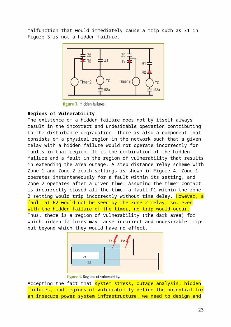
operating problems during unusual supply/demand patterns. Given this observation, we suggest that one needs manageable on-line metrics for estimating the severity of system conditions and, based on these metrics, a means of adjusting the control logic to make the most out of what is available. The implications of this on system model requirements are that one needs flexible models and monitoring tools for assessing the severity of system conditions and for adjusting the control logic accordingly as conditions vary within their hardware limits.Depending on the duration of the problem, one could allow temporary limit violations, delaying the disconnection of the protected equipment and, therefore, localizing the effect of the initial outage. This situation, however, would definitely raise the need for special protection schemes (remedial action schemes) (SPSs) to adjust the protection of the individual pieces of equipment to the system-wide conditions.5 The SPS should also be used when control fails. The challenge is to define the type of information needed and its best use for overcoming the problem of uncoordinated disconnection of devices during emergency conditions. The implications of adopting such an approach are potentially far-reaching. As a basic example, transfer limits on key corridors would continuously be adjusted, drawing on all available resources for maximizing transfers, instead of assuming that transfer limits are determined only infrequently in an off-line mode. Another qualitative implication is that if this is done right, control adjustments would be systematic with respect to time, locations and type of controllers acting. For better or worse, modern-day electric power systems have many diverse types of controllers. It takes a tremendous intelligence to draw in an orderly manner on their overall potential as conditions change, without making matters worse.B. Role of Control for Implementing Efficient Economic Delivery in a Restructuring Electric Power IndustryImportant for the purposes of the concepts put forward in this paper is the fact that the control capacity needed to keep the system reliable, everything else being the same, greatly depends on the overall on-line monitoring, decision and control framework (logic, type, information supporting decisions, etc.) Planning and using reserve capacity (including control) for this purpose has been an off-line activity based on extensive numerical simulations and/or human experts’ knowledge about the specifics of the situation.As the economic pressures increase, it is becoming more relevant to reduce capacity for the same performance by relying on just-in-time decision making. It is conjectured and illustrated in Section VII that generally more adaptive systematic use of available control reserves results in wider reliable ranges of operating conditions, all else being equal. In addition, since the services are provided at value, it is essential to enhance the value by means of control and communications. Various tradeoffs between the cost of reduced stand-by reserve by means of enhanced control, the cost of control/communications equipment and the values to industry participants and the system as a whole must be evaluated in the changing industry as the new hardware is being considered [48].
23
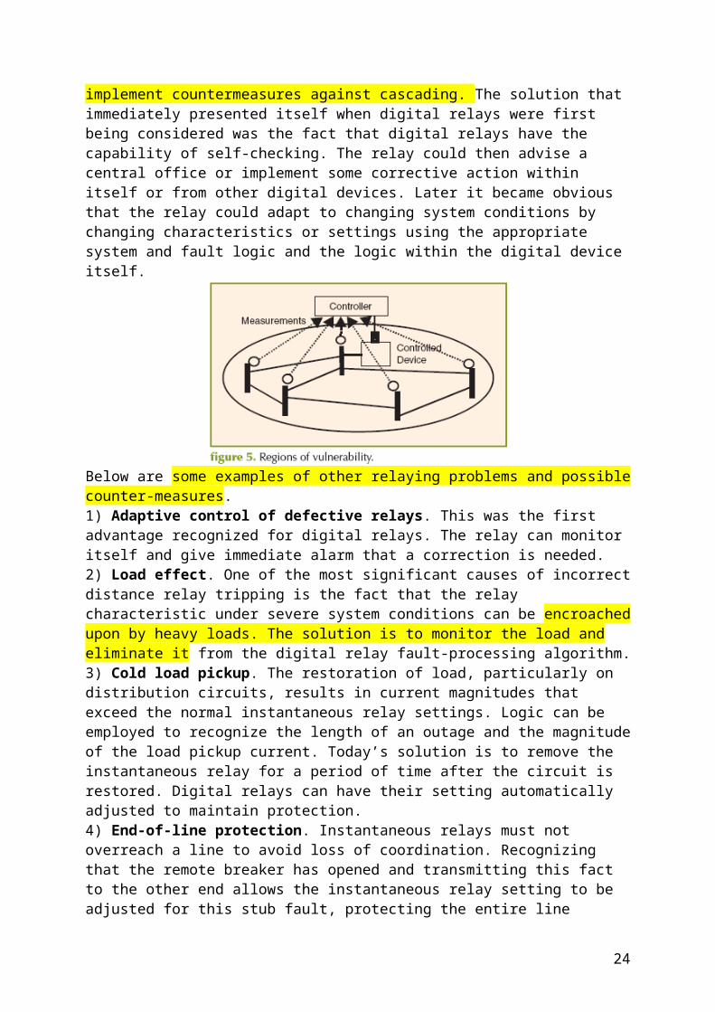
{Opis problemów związanych z aktualnymi układami regulacji AGC i AVC}
IV. HIERARCHICAL CONTROL SYSTEMS OF A MULTIAREA INTERCONNECTIONThe basic objective of today’s hierarchical control is to ensure that customers are served electricity of high quality at reasonable prices. This very broad objective is effectively accomplished within a horizontally structured interconnection by performing technical subobjectives at various hierarchical levels and over various time horizons. In a fully regulated industry these subtasks were fully defined within the utility (control area) boundaries. Traditional control areas (utilities) have built their transmission and production equipment to meet these objectives for the forecast load in their own area. Various complexities related to the interactions with neighboring utilities were resolved to a large extent through a design which has led to strong utility networks and weak interconnections between utilities. The implications of such design on the overall use of resources within the interconnection are briefly described next in the context of hierarchical control underlying the operation of such architecture.A. Temporal and Spatial Decomposition of Control Tasks for Normal OperationsBased on the assumptions described in Appendix B, current hierarchical control is temporally decomposed so that the forecast load is supplied somewhat independently from the minute-to-minute automated regulation of power imbalances, and the regulation is, in turn, performed separately from the stabilization by the primary controllers of the individual pieces of equipment. These are, of course, interdependent, because power scheduling is performed by adjusting the set points of the controllers on power plants, and regulation is also done by adjusting the set points of power plants specifically dedicated to functions such as automatic generation control (AGC) or automatic voltage control (AVC) [13].Stabilization is in response to fast load fluctuations so that the set points of the controllers remain at the values set by scheduling and regulation.6 This decomposition is based on the multitemporal separation of a time-varying system load as well as on the intended decomposition of control tasks in balancing power.Current control practices have evolved over time, and have never been designed to meet a prespecified reliable performance according to the objectives stated in Section III. Similarly, the models for the particular subfunctions (stabilization, regulation) have not been developed with the objective of being used in a control design aimed at meeting a prespecified performance. The process of gradual automation of electric power system operation has instead been primarily driven by often ingenious engineering inventions related to controlling the system at a particular spatial and temporal level (primary control of generator-turbine- governor (G-T-G) sets; scheduling and AGC of each control area (and its AVC counterpart in Europe); and, more recently, fast power-electronic switching of transmission network components for fast stabilization).The net result of this uncoordinated process viewed from the interconnection level is a mix of many nonuniform (with respect to
24
location, rate of response and type) controllers at individual pieces of equipment, as well as at each utility (control area) level. There is currently no on-line coordination of individual control areas within an electric interconnection. Consequently, it is practically impossible to predict the performance of closed-loop interconnection dynamics for any significant variations around the assumed (preagreed upon) conditions. The complexity in hand is, by many measures, unmanageable without imposing many explicit or implicit assumptions.{Rozwiązaniem jest współpraca między podmiotami energetycznymi}B. Cooperation as a Means of Managing the Interconnection and Its ComplexityThe overall effectiveness of today’s hierarchical control is based on the notion that each layer meets, in an entirely decentralized way, its own subobjective and that, as long as all members in each layer perform their own subtasks, the interconnection as a whole operates reliably. In particular, the primary controllers in power plants are tuned to stabilize their own local dynamics, assuming that all other power plants will do the same and maintain the system conditions as planned. Similarly, each utility performs its own supply–demand balancing via its own AGC, assuming that all other control areas are doing the same. Furthermore, all utilities attempt to schedule their own generation to supply forecast load, and send agreed upon power to the neighboring control areas. This overall operating practice is fundamentally reflected in: 1) the models used for scheduling, regulating the interconnection as a whole; 2) the spatial decomposition of tasks; and 3) the temporal decomposition.Modeling and control design is invalid and ineffective unless each member within each hierarchical layer acts accordingly. In other words, it is practically impossible to have provable performance by the hierarchical control, decomposed both spatially and temporally, unless all agents meet their objectives. For example, it is well known that it is very hard, or impossible, for a single control area to schedule generation in a decentralized way unless all interconnected control areas also meet their preagreed upon schedules simultaneously. In the regulated industry, the principles of each control area meeting its own share have mainly been implied as part of normal operations [33]. We next describe the temporal decomposition of control objectives.{Kolejnym problemem jest bilansowanie mocy}
{Tradycyjnie było tak}In a horizontally structured interconnection, each control area schedules its own power supply to provide for its own (native) customers. This is done for prescheduled real power net power exchanges with the neighboring utilities. Current operating practice is for each control area (utility) to schedule in a feed-forward manner real power generation to supply its own forecast demand for given net real power flow exchange with the neighboring utilities. Finally, as each control area attempts to schedule its net tie-line flow with neighbors, it is assumed that the interconnection as a whole will have a steady-state equilibrium, i.e that a power flow solution of the entire interconnection exists.
25
Another way of interpreting this assumption is that the control areas are weakly connected, implying that each control area can schedule net tie-line exchange and maintain it in response to both internal and external perturbations [41].We illustrate in Section VII potential problems that arise when the interconnection is used beyond the conditions which ensure the validity of this assumption.An important observation concerning this decentralized approach to scheduling, regulation and stabilization is that for the interconnection as a whole to perform adequately it is essential that each control area meet its objectives. System design and capacity is planned and scheduled so that this load is supplied even during any single equipment failure.This means that the system is expected to have a power-flow solution for any single equipment loss, including the existence of a transiently stable postfault equilibria. It is difficult to imagine that exhaustive simulations can be performed for all possible scenarios even in the case of a small system. Such simulations are currently carried out by the industry to determine sufficient reserve for each control area and for regions. Each utility has in its control center a variety of computer-based and human-assisted approximate methods for assessing the severity of contingencies as they occur.
{Urządzenia, jakie do tej pory wykorzystywano w tym celu są następujące}Another important means of regulating forecast real power imbalances are phase-angle regulators (PARs). These are line transformers whose taps are adjusted to maintain real power flows within the preset thresholds.Frequency fluctuations caused by random fluctuations in real power load are compensated for in an automated way by the governors controlling the amount of mechanical power applied by their prime movers. An important observation is that governor control is inherently a proportional type controller that does not compensate for the steady-state error in frequency deviations from the nominal frequency and/or tie-line schedules requiring a system-wide time-error correction by a dedicated power plant in order to compensate for the effects of the inadvertent energy exchange (IEE) between utilities. Finally, the fastest random deviations of generator voltages and frequencies are stabilized by the AVRs and PSSs of power plants. The tuning of these controllers is generally intended only for stabilizations of small disturbances. All controllers are constant-gain controllers, and are intended to stabilize disturbances around a statically and dynamically stable equilibrium. {Wada aktualnie stosowanych rozwiązań}These controllers are generally not capable of taking the system from a prefault equilibrium to a stable postfault equilibrium outside the stability region of the prefault equilibrium. It is shown in Section VII how more advanced control in large-scale systems can be applied to achieve this.
{Regulacja mocy biernej}D. Reactive Power Scheduling, Regulation and StabilizationScheduling and regulation of reactive power during normal conditions is done in a somewhat decoupled way from real power scheduling. Moreover,
26
ensuring sufficient reactive power and voltage scheduling capacity has not been as standardized as real power capacity scheduling. Reactive power support can be provided either by the power plants, or by installing capacitive support to compensate for large reactive power transmission losses, or by installing shunt capacitors electrically close to the load centers. Current industry practices vary from keeping a large portion of reactive power capacity in generators for voltage scheduling as needed, to a more active scheduling and regulation by adjusting the set points of AVRs for supplying forecast reactive power load , and for regulating slow reactive load deviations by the Automatic Voltage Control (AVC); the latter practice is used in France, Italy and Spain, in particular. 1) Mechanically Switched Capacitors and Transformers:Over time, different technologies have evolved for regulating medium- and long-range voltage deviations by adjusting reactive power support in the transmission system. In particular, mechanically switched on-load tap-changing transformers (OLTCs) [35] and shunt capacitors are routinely used for load voltage regulation. This is done by regulating the number of active taps in mechanically switched capacitor banks so that the steady-state load voltage is kept within the prespecified limits; most often this is done by adjusting OLTCs to control the number of active taps of the line transformer in order to regulate directly the receiving end load voltage; less frequently, the switching actions regulate remote voltages elsewhere within the system. The process of regulating load voltage subject to power-flow constraints can be described as a control-driven process subject to the common algebraic constraint imposed by the need to meet the basic power flow balance at each quasistatic step. The convergence of this process driven by the mechanical switching of capacitor banks and OLTCs is critical for the stable regulation of load voltages within each utility, region and/or interconnection [36].
{Zawodność rozwiązań regulacji mocy biernej – problemy się pojawiają jak zabrakło mocy biernej}
Several blackouts have been related to the “malfunctioning” of these devices, ultimately resulting in system-wide voltage collapse. The fundamental difficulty in such situations has been the inability of these switching devices to adjust their logic when there is not enough reactive power reserve. It has been shown that relaxing the currently implemented control, which essentially absorbs a constant amount of reactive power by forcing the voltage to remain within a small band, to a more adaptive scheme of reducing reactive power requirements temporarily under unusual circumstances could return the system to a more manageable condition and help the system as a whole to avoid voltage collapse [36]. In particular, recognizing a change in the qualitative characteristics of the system Jacobian derived from the model in Appendix A that defines changes in voltages as driven by the mechanically switched tap changers, and adjusting the control logic to reflect and compensate for the change, could help regulate voltages back to within the acceptable limits and avoid a system-wide voltage collapse [36]. This can be implemented as a sliding-mode type controller, but has not been implemented in practice; its
27
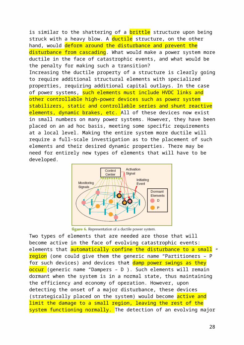
potential may be significant. For purposes of assessing the overall potential of enhanced control, it is critical to consider the malfunctioning of a variety of reactive mechanically switched devices currently available in large numbers in typical transmission and distribution systems. Assessing how much of the reactive power burden now borne by generation could be reduced by more effective use of these resources in more adaptively regulating reactive power in transmission and distribution should be one of the main R & D objectivesfollowing the August 2003 blackout, in particular.{Rola stabilizatorów}E. The Key Role of Stabilizing Control in Operating an Electric Power InterconnectionThe increase in operating demands and the proliferation of advanced hardware have created a need for more powerful tools for planning and design. In many cases, the function of a particular piece of equipment may be defined in terms of a narrow set of objectives, such as the stabilization of a particular bus voltage or modulation of the power flows across a particular transmission interface, without addressing the system-wide effects of the device. This situation follows from the lack of a comprehensive design methodology for power system stabilization. The effect of this is that the selection and application of the equipment is done without any systematic method of ensuring that the control objectives are met adequately, efficiently, and without unforeseen consequences.Indeed, once the selection of a particular piece of equipment is made, the use of exhaustive time-domain simulations is currently the only method available for attempting to ensure that all of its capabilities are exploited, in the sense of fully realizing system-wide or even local benefits. The development of a coherent set of tools for evaluating the performance of various control devices in terms of immediate control objectives and system-wide effects must, therefore, be viewed as critical to the effective utilization of power electronically switched transmission and distribution network controllers (generically referred to as FACTS); the FACTS technology is very different from traditional mechanical switching because it is capable of enhancing fast power plant controllers and can be used as a means of implementing advanced control as it becomes available. It should be clear that if either primary controllers, such as governors, AVRs and PSSs, fail to stabilize fast dynamics, and/or the AGC fails to regulate the tie-line flows to their scheduled values, there exists the possibility of intercontrol area oscillations at various rates and of different degrees of severity that can threaten system stability [20], [21].
{Aktualne stosowane praktyki po wyłączeniu elementów SEE}
V. CURRENT PRACTICES FOR CONTROLLING DURING EQUIPMENT OUTAGESAs long as no major unplanned loss of equipment occurs, frequency and voltage deviations are kept within acceptable limits by the described stationary real-power prescheduling, the secondary-level AGC, regulation using mechanically switched controllers, and stabilization by constant-gain primary controllers. This rather simple control works well for relatively
28

small load deviations around the nominal pattern for which the system is designed.Current operating practice to ensure reliability identifies the “worst case” scenario for transient stability, and makes sure that sufficient reserve capacity is kept between the nominal operating point and the worst case condition, so that during such a fault a stable postfault equilibrium may be found. Both transient and dynamic stability studies are done off-line for such worst-case scenarios. A typical approach has been to simulate P-V steady-state transfer curves; assuming a constant ratio of real and reactive power demand consumption (power factor), off-line power-flow studies are carried out to obtain a dependence of receiving end voltage in the real power transfer . On the other hand, these simulations establish the maximum real power flow allowed. It is straightforward to conclude from the simple numerical examples that the maximum feasible real power transfer could be greatly affected by the AVR settings, which determine the voltages at generator nodes as long as there is sufficient excitation control available. Currently used industry software for calculating this line power transfer limit does not account for the potential of increasing the transfer by optimizing system voltages. Moreover, many other discrete-type control actions (OLTCs, switching capacitors on the load side) are not accounted for as this limit is computed. As a result, the computed limit is generally conservative.In the on-line setting a contingency screening test is performed prior to dispatching real power generation to ensure that the system will be feasible for real power supply and delivery during any contingency. Linearized, distribution factor-based simulations are done for all contingencies.8 More detailed power flow simulations are done for the list of contingencies determined to be critical. This amounts to restricting real power generation dispatch so that the line-flow limit does not exceed the maximum feasible transfer. For example, economic generation transfer is limited by this calculation, in case a limiting contingency happens to occur.This practice is preventive, and not corrective in its basic nature. The basic inability to schedule the least-expensive generation because of necessary stand-by reserves in case an outage occurs, generally results in economically suboptimal cumulative use of resources during normal operation.Moreover, despite the fact that the reserve is kept, there is no guarantee that the system will be feasible during an actual equipment failure. More generally, the N-1 reliability reserve is assured for the assumed nominal load prior to the equipment outage. The planning studies may not be sufficient to ensure that the system will perform its basic function during the single equipment outage because at the time of the outage the loading and other conditions in the system may be considerably different than the conditions assumed at the planning stage. The closer the nominal (prefault) operating point is to the infeasible operating point, the smaller the next change is that causes the system to lose its feasibility, steady-state and/or transient. This very fact may have been crucial during the August 2003 blackout. As the loading conditions increased for economic transfers, the closer the nominal point (prior to equipment failures) may
29

have come to the system feasibility and/or stability boundary. The effects of hard-to-predict equipment failures around such an operating point are, at least in principle, not computable by DF-based computations.Possibly the most critical aspect of today’s operations is the fact that as the system conditions approach small-signalor transient instability the constant-gain slow control may no longer be effective. This is particularly true over broad ranges of disturbances of one type or another. Because of this, introducing a more adaptive logic that ensures system-wide stabilization is essential. Given the assumptions underlying today’s hierarchical control, unless the system is stable, regulation and scheduling according to temporal and spatial decomposition become ineffective.In what follows, we propose a possible multimodal approach to monitoring and controlling a complex electric power interconnection. This approach takes into consideration today’s operating practices and, much like the early DyLiacco diagram suggested classification of conditions into normal, alert, emergency and restorative [4], [5], it proposes to use a family of QIs for detecting and quantifying the degree and type of abnormality and, based on this, adjust the underlying control. Again, the key to the overall enhancement is that the system be made closed-loop stable. Once this is ensured, the multilayered hierarchy already in place needs only to be made slightly more adaptive for the ensured reliability of the interconnection as a whole.
{propozycja rozwiązania – model wielowarstwowy, wielomodalny regulacji SEE }
VI. TOWARD A MULTIMODAL, MULTILAYERED MONITORING AND CONTROL OF FUTURE ELECTRIC POWER SYSTEMSAs electric power grids are operated away from the conditions for which they were initially designed, they may lose the properties of weakly interconnected stable networks. Consequently, the hierarchically managed system may fail to meet its objectives. The variations in system conditions are generally caused by significant variations in operating conditions and/or by major equipment failures. There is no distinct line between the effects of these two. As a matter of fact, it is well documented that often qualitative changes occur as the controllers reach their limits and the degree of controllability becomes compromised [23]. It is plausible that similar problems may take place if a critical measurement becomes unavailable, and the system is less observable.Regardless of the actual root causes of such changes in the qualitative response of an electric power system, the hierarchical decomposition-based operation may result in very unpredictable events when the underlying assumptions are violated. It is a conjecture of the first author that this was the case during the later stages of the August 2003 blackout.The current approach is to rely on complicated off-line simulationsof similar scenarios and to use these to assist human operators with the decision making under such conditions. These off-line studies are very time-consuming and are done for prescreened most critical equipment failures. This preventive approach requires expensive stand-by reserves
30

that, no matter how large, may not ensure guaranteed performance [47], [49].A. A Multimodal, Multilayered Monitoring and Control FrameworkIn Appendix A, we review fundamental modeling for managing complex electric power networks over broad ranges of operating conditions and equipment status. The modeling is structure-based, and it represents an outgrowth of a structure-based modeling approach initially developed for the enhanced operation of electric power grids during normal conditions [13], [20], [21]. In this section, we propose a decision-making approach based on these models.The approach uses the formalized hierarchical models to explicitly monitor and ensure through adaptive control a predictable response of the closed-loop interconnection dynamics. The novel aspect of this approach is that, even when the system does not exhibit such response without enhanced control, the control is adapted to ensure such response.Predictable system response conditions are conceptually ensured in several steps: (0) on-line monitoring of the status of the QIs relevant for detecting modal changes; 1) by enhancing the logic of the local equipment controllers [38] by stabilizing system dynamics as the properties of QIs change in a qualitative way; and 2) by adaptively changing on-line the settings of the equipment controllers, in order to re-direct the existing resources as the operating conditions vary outside the acceptable ranges. At the subsystem (control area) level and the interconnection level QIs introduced in Appendix A are used to monitor how far these are from their values specified for normal conditions. As the QIs approach the threshold of their normality, the basic monotonic system assumptions cease to hold. The QIs effectively become precursors of abnormal conditions. The status of the QIs becomes, in turn, an indicator that the logic of primary controllers needs to be adjusted in order to induce a closed-loop monotone response of system dynamics. The transition from normal to less normal conditions and the control adaptation are fairly seamless both in time and space.The multimodal features are as follows: As long as the status of the QIs is such that the currently implemented hierarchical control is effective, the system operations and control resemble current practices. However, as conditions vary, for a variety of triggering causes, the QIs are monitored and used to re-schedule the other resources and keep the interconnection as close to normal as possible by means of hierarchical control. An illustration of using QIs for enhancing reliability on-line over the broad ranges of power transfers is given in Section VII. A major open R & D question concerns the development of effective algorithms for relating properties of QIs, with the procedures currently used by the power system operators for deciding on various levels of operational severity.The following are basic essential steps for an enhanced control design which builds upon today’s hierarchical control. Its objective is to support on-line monitoring and control for enhanced reliability with provable performance as defined in the Section VI.
Define bounds on disturbances (demand deviations and/or classes of equipment failures) for which control is expected to ensure a reliable performance.
31
Formulate limits on control (actuators). Design a multirate state estimators for providing the information
about the type of operating ranges for which the quasistationary control (scheduling) and stabilizing feedback are needed.
Use the information from the state estimators to automate on-line corrective actions for optimizing the use of available controls.
Use the information from the state estimators to adjust the control logic of the primary fast controllers on individual pieces of equipment (power plants, transformers, and transmission lines in particular).
Use the information from the state estimators on a slower time scale to adjust the constraints on the output variables so that the system stabilization is ensured as the system is optimized in a quasistationary way [39].
B. The Key Role of QIs as the Precursors of Abnormal OperationsWe close by observing that steady-state and small-signal stability are ensured for the operating points satisfying the qualitative indices (QIs)’ normal status; the QIs are characterized for the closed-loop dynamics and, therefore, depend fundamentally on the control logic implemented. For example, the system Jacobian defining small-signal dynamics depends, among other factors, on the control logic of the fast primary controllers. Keeping this in mind, it becomes possible to take a pragmatic approach to ensuring stable operations over broad ranges of operating conditions in two steps, namely by 1) identifying the basic nature of the system QIs; and 2) by sending signals to the primary controllers to adjust their logic as the system approaches ranges where the QIs may change their normal status unless this adjustment is done. The role of QI characteristics as the qualitative precursors of instability has been studied to a lesser extent in the context of continuous dynamics. Analogous qualitative precursors have been studied more extensively in the context of potential mid-range voltage instabilities related to the malfunctioning of OLTCs and their implications on some early voltage collapse-related blackouts [30], [36].It is essential that we make progress toward computationally manageable precursors for on-line detection of abnormal QIs. Questions concerning the reduced information we have for detecting this abnormality are essential to resolve, yet very little progress has been made in this overall area. A particularly challenging task here comes from the change in the QIs’ characteristics due to control saturation. A qualitative change in control logic is also needed for enhanced switching of OLTCs and capacitor banks when system conditions are transiently stable but statically unstable [36].C. The Key Role of High-Gain Power-Electronically Switched ControllersGiven the enormous challenge of one’s inability to characterize the regions of abnormality, operating complex power systems in hard-to-predict, not well-understood operating regions raises basic questions concerning the ability of current electric power system to survive instabilities of various types. The basic potential of fast power electronically switched control is significant, provided the control design is carried out systematically. Adding fast network control is essential because most of the existing primary controllers are too slow to stabilize the system dynamics outside normal operating ranges. The slowest control available in power plants
32

which might be candidates to stabilize the system are the field excitation and the valve position. Given that neither of these controls directly affects the electromechanical dynamics of generators (swing equation), the only way for these controllers to stabilize the electro-mechanical variables to keep generators in synchronism, is to apply the high-gain field excitation control [40] and/or the fast valving control [41]. This further means that the closed-loop dynamics, when affected by the high-gain controllers, is no longer time-scale separable, and the control design becomes more complicated. An example of such inadequate control design of AVRs has been known for quite some time [10]. This has led to the need to introduce enhanced field excitation control by designing PSS control; the PSS control design offers truly enhanced control because it responds to both electromagnetic and electromechanical variables and their rate of change, rotor acceleration in particular.Further enhancements of field excitation control have been designed which recognize the nonlinear nature of the power system dynamics. In particular, several nonlinear control techniques have been tried and compared for their performance in [44] and [45]. In [44], a comparison of several nonlinear control methods for transiently stabilizing the system when constant gain control, including the conventional PSSs, fails to achieve this, is carried out. The effectiveness of these methods depends on how the total system energy is managed during difficult transients. The potential benefits of such a control design are illustrated in Section VII.We mention important technological breakthroughs for fast stabilization of transient dynamics which are not traditional generation control means. These technologies are commonly referred to as FACTS [7]. They offer previously unavailable means of stabilizing dynamics by fast power-electronic-based switching, which control how much of the series- and/or shunt- capacitances and inductances are connected to the system. Without going through a detailed treatment, we suggest that, for any of these controllers to transiently stabilize system dynamics, it is necessary that they be fundamentally high-gain.Similarly, fast load control, in addition to generally un-modeled self-stabilizing load effects, would require high gain feedback as well. The R & D in support of high-gain control on generators, transmission system and loads represents a major opportunity and a major challenge. An ultimate vision for making the existing ac power system “all dc” by distributed high-gain compensation is described in [46] and [56]. The trade-offs between the benefits from such control, costs and risks must be carefully studied. The power-electronic-based transmission and load control via FACTS is fundamentally a switched-mode control and, as such, lends itself naturally to the robust sliding-mode implementations of several key high-gain nonlinear controller types. This indicates a major potential for implementing FACTS technologies systematically.Finally, we use the example of sliding mode control design to bring up another major challenge. Defining the best sliding mode surface, i.e. the surface to which the dynamics should be stabilized during large disturbances, remains largely an open problem for large-scale systems such as the electric power systems. It was shown in [38] how the choice of postfault equilibria or sliding surface, combined with feedback linearizing
33
controller (FBLC), greatly outperforms the same nonlinear control without careful choice of postfault surface. This development builds upon the early concepts of observation decoupled state space for electric power systems [52].Once more, one observes that transient stabilization without careful steady-state equilibria choice may not be as effective as it may be possible. Most generally, a sliding mode approach to transient stabilization lends itself well to the problem when constant-gain controllers fail to work.
REFERENCES [1] “NERC interim report: Causes of the August 14th blackout in the United States and Canada” U.S.–Canada Power System Outage Task Force [Online]. Available: http://www.nerc.com/~filez/ blackout.html [2] “NYISO final report on the 2003 blackout” Feb. 8, 2005 [Online]. Available: http://www.nyiso.com [3] “DoE blackout report” [Online]. Available: http://www.doe.gov [4] T. Dy Liacco, “The adaptive reliability control systems,” IEEE Trans. Power App. Syst., vol. PA S-86, pp. 516–531, 1967. [5] L. H. Fink and K. Carlsen, “Operating under stress,” IEEE Spectrum Mag., pp. 48–53, Mar 1978. [6] S’. Trudel, S. Bernard, and G. Scott, “Hydro quebec defense plan against extreme contingencies,” presented at the IEEE Power Engineering Meeting, New York, 1998, PE-211-PWRS-06-1998. [7] N. Hingorani and L. Gyugui, Understanding FACTS: Concepts and Technology of Flexible AC Transmission Systems. New York: Wiley, 2002. [8] E. H. Allen and M. Ilic, “Interaction of transmission network and load phasor dynamics in electric power systems,” IEEE Trans. Circuits Syst. I: Fundamental Theory and Applications, pp. 1613–1620, Nov. 2000. [9] A. Bergen, “Analytical methods for the problem of dynamic stability,” in Proc. IEEE Int. Symp. Circuits and Systems pp. 864–871. [10] F. P. DeMello and C. Concordia, “Concepts of synchronous machine stability affected by excitation control,” IEEE Trans. Power App. Syst., vol. PAS-100, pp. 3017–3024, 1981. [11] E. V. Larsen and D. A. Swann, “Applying power system stabilizers, parts I, II and III,” IEEE Trans. Power App. Syst., vol. PAS-100, pp. 3017–3046, 1981. [12] V. Venkataqsubramanian, H. Schattler, and J. Zaborszky, “Local bifurcations and feasibility regions in differential-algebraic systems,” IEEE Trans. Autom. Control, vol. 40, pp. 1992–2013, 1995. [13] M. D. Ilic and S. X. Liu, Hierarchical Power Systems Control: Its Value in a Changing Electric Power Industry, ser. Advances in Industrial Control. London, U.K.: Springer-Verlag, 1996. [14] A. Bergen and V. Vittal, Power Systems Analysis. Upper Saddle River, NJ: Prentice-Hall, 1999. [15] L. Petzhold, Numerical Methods for DAEs-Current Status and Future Directions in Computational ODEsJ. R. Cash and I. Gladwell, Eds. Oxford, U.K.: Oxford Univ. Press, 1992. [16] M. L. Crowand M. Ilic, “The parallel implementation of thewaveform relaxation method for transient stability simulations,” IEEE Trans. Power Syst., vol. 5, no. 3, pp. 922–932, Aug. 1990. [17] Automatic Learning Techniques in Power Systems. Norwell, MA: Kluwer Academic, 1998. [18] R. J. Marceau, R. Malihot, and F. D. Galiana, “Ageneralized shell for dynamic security and operations planning,” IEEE Trans. Power Systems, vol. 8, no. 3, pp. 1098–1106, Aug. 1993. [19] M. Ilic, F. D. Galiana, L. H. Fink, A. Bose, P. Mallet, and H. Othman, “Large transmission capacity in power networks,” Elect. Power Energy Syst., vol. 20, pp. 99–110, 1998. [20] M. Ilic and S. X. Liu, “A simple structural approach to modeling and analysis of the interarea dynamics of the large electric power systems: Part I—Linearized models of
34
frequency dynamics,” in Proc. 1993 NorthAmerican Power Symp. Washington, DC, Oct 1993, pp. 560–569. [21] M. Ilic and S. X. Liu, “A simple structural approach to modeling and analysis of the interarea dynamics of the large electric power systems: Part II—Nonlinear models of frequency and voltage dynamics,” in Proc. North American Power Symp. Oct 1993, pp. 570–578. [22] C. Desoer and E. Kuh, Basic Circuit Theory. New York: Mc-Graw-Hill, 1969. [23] M. D. Ilic and J. Zaborszky, Dynamics and Control of Large Electric Power Systems. New York: Wiley Interscience, May 2000. [24] P. Kundur, Power System Stability and Control. New York: Mc-Graw Hill, 1993. [25] US FERC NOPR on RTOs 2000. [26] R. Kaye and F. Wu, “Analysis of linearized decoupled power flow approximations for steady-state security assessment,” IEEE Trans. Circuits Syst., vol. CAS-31, no. 7, pp. 623–636, Jul. 1984. [27] P. Kokotovic, H. Khalil, and J. O’Reilly, Singular perturbation Methods in Control: Analysis and Design. Orlando, FL: Academic, 1986. [28] D. Siljak, Decentralzied Control of Complex Systems. NewYork: Academic, 1991. [29] M. Ilic, S. X. Liu, B. D. Eidson, C. Vialas, and M. Athans, “A structure-based modeling and control of electric power systems,” IFAC Automatica, vol. 33, pp. 515–531, Mar. 1997. [30] J. P. Paul, J. Y. Leost, and J. M. Tesseron, “Survey of secondary voltage control in France,” IEEE Trans. Power Syst., vol. PWRS-2, May 1987. [31] A. Carpasso, E. Mariani, and C. Sabelli, “On the objective functions for reactive power optimization,” presented at the IEEE Winter Power Meeting, 1980, A 80WM 090-1. [32] D. Ewart, “Performance under normal conditions,” in Proc. Syst, Eng. Power: Status and Prospects NH, 1975. [33] “Report on Interconnected Operation services (IOS),” North American Electric Reliability Council (NERC), 1997. [34] E. Allen, M. Ilic, and J. Lang, “The NPCC equivalent system for engineering and economic studies,” IEEE Trans. Power Syst., submitted for publication. [35] M. S. Calovic, Regulation of Electric Power Systems [in Serbian]. Belgrade, Serbia: Vizartis, 1997. [36] J. Medanic, M. Ilic, and J. Christensen, “Discrete models of slow voltage dynamics for ULTC coordination,” IEEE Trans. Power Syst., vol. PWRS-2, pp. 873–882, 1987. [37] P. W. Sauer and M. A. Pai, “Power system steady-state stability and the load-flow Jacobian,” IEEE Trans. Power App. Syst., no. 4, pp. 1374–1381, Nov 1990. [38] J. W. Chapman, M. D. Ilic, and C. A. King et al., “Stabilizing a multimachine power system via decentralized feedback linearizing excitation control,” IEEE Trans. Power Syst., vol. PWRS-8, no. 3, pp. 830–839, Aug. 1993. [39] M. Ilic´, “Automating operation of large electric power systems over broad ranges of supply/demand and equipment status,” in Applied Mathematics for Restructured Electric Power Systems, J. Chow, W. Wu, and J. Momoh, Eds. Norwell, MA: Kluwer Academic, ch. 6, pp. 105–137, ISBN 0-387-23 470-5. [40] J. Chow, J. Winkelman, M. A. Pai, and P. W. Sauer, “Application of singular perturbations tehory to power system modeling and stability analysis,” in Proc Am. Control Conf. 1985. [41] M. M. Gavrilovic, “Optimal control of SMES systems for maximum power system stability and damping,” Int. J. Electr. Power Energy Syst., vol. 17, no. 3, p. 343, Jun. 1995. [42] M. Ilic, J. Lang, R. Gonzales, E. Allen, and C. King, “Benchmark optimal solution for the NPCC equivalent system,” IEEE Trans. Power Syst., submitted for publication. [43] V. R. Schmitt, J. W. Morris, and G. D. Jenny, Fly-by-Wire. Leesburg, VA: Avionics Communications, Inc., 1999. [44] C. A. King, J. W. Chapman, and M. D. Ilic, “Feedback linearizing excitation control on a full-scale power system model,” IEEE Trans. Power Syst., vol. 9, no. 2, pp. 1102–1111, May 1994. [45] V. I. Utkin, “Variable structure systems with sliding control,” IEEE Trans. Autom. Control, vol. AC-22, pp. 212–222, Apr. 1977. [46] J. Zaborszky and M. Ilic, “Exploring the potential of the All DC (ADC) bulk power systems,” presented at the Bulk Power System Dynamics and Control V, Onomichi, Japan, Aug. 26–31, 2001, (plenary paper).
35
[47] M. Ilic, “Regulatory/market and engineering needs for enhancing performance of the U.S. electric power grid: alternative architectures and methods for their implementation, invited session “Informational and control reliability challenges in modern power systems,” presented at the 8th World Multi-Conf. Systemics, Cybernetics and Informatics (SCI’2004), Orlando, FL, Jul. 18–21, 2004. [48] M. Elizondo and M. Ilic´, “Toward markets for system stabilization,” presented at the IEEE General Power Engineering Meeting, San Francisco, CA, Jul. 2005. [49] M. Ilic, “Toward a multi-layered architecture of large-scale complex systems: Reliable and efficient man-made infrastructures,” presented at the MIT/ESD Symp., Cambridge, MA, Mar. 29–31, 2004. [50] M. Ilic-Spong, M. Spong, and R. Fischl, “The no-gain theorem and localized response for the decoupled P-O network with active power losses included,” IEEE Trans. Circuits Syst., vol. CAS-32, no. 2, pp. 170–177, Feb. 1985. [51] M. Ilic-Spong, J. Thorp, and M. Spong, “Localized response performance of the decoupled Q-V network,” IEEE Trans. Circuits Syst., vol. CAS-33, no. 3, pp. 316–322, Mar. 1986. [52] J. Zaborszky, K. W. Whang, K. V. Prasad, and I. Katz, “Local feedback stabilization of large interconnected power systems in emergencies,” IFAC Automatica, pp. 673–686, Sep. 1981. [53] NETSS Solution to Value-Based On-Line Voltage/Reactive Power Service in the Changing Electric Power Industry Feb. 16, 2004, (available at request from the first author). [54] NETSS IT-Based Solution to the Seams Problem Oct. 10, 2003, (available at request from the first author). [55] National Science Foundation, Toward a Multi-Layered Architectures for Reliable and Secure Large-Scale Networks: The Case of an Electric Power Grid, NSF ITR Project Principal Investigator M. Ilic´. [56] M. Ilic, “Toward a multi-layered architecture of large-scale complex systems: Reliable and efficient man-made infrastructures,” presented at the MIT/ESD Symposium, Cambridge, MA, Mar. 29–31, 2004.
{Centra sterowania przyszłości – od SCADA do WAMS}{bardzo ważny artykuł !}
Power System Control Centers: Past, Present, and FutureFELIX F. WU, KHOSROW MOSLEHI, AND ANJAN BOSEPROCEEDINGS OF THE IEEE, VOL. 93, NO. 11, NOVEMBER 2005
I. INTRODUCTIONThe control center is the central nerve system of the power system. It senses the pulse of the power system, adjusts its condition, coordinates its movement, and provides defense against exogenous events. In this paper, we review the functions and architectures of control centers: their past, present, and likely future.We first give a brief historical account of the evolution of control centers. A great impetus to the development of control centers occurred after the northeast blackout of 1965 when the commission investigating the incident recommended that “utilities should intensify the pursuit of all opportunities to expand the effective use of computers in power system planning and operation . Control centers should be provided with a means for rapid checks on stable and safe capacity limits of system elements through the use of digital computers.” [1] The resulting computer-based control center, called the Energy Management System (EMS), achieved a quantum jump in terms of intelligence and application software capabilities. The requirements for data acquisition devices and systems, the associated communications, and the computational power within the control center were then stretched to the limits of what computer and communication technologies could offer at the time.
36

Special designed devices and proprietary systems had to be developed to fulfill power system application needs. Over the years, information technologies have progressed in leaps and bounds, while control centers, with their nonstandard legacy devices and systems that could not take full advantage of the new technologies, have remained far behind. Recent trends in industry deregulation have fundamentally changed the requirements of the control center and have exposed its weakness. Conventional control centers of the past were, by today’s standards, too centralized, independent, inflexible, and closed.The restructuring of the power industry has transformed its operation from centralized to coordinated decentralized decision- making. The blackouts of 2003 may spur another jump in the applications of modern information and communication technologies (ICT) in control centers to benefit reliable and efficient operations of power systems. The ICT world has moved toward distributed intelligent systems with Web services and Grid computing. The idea of Grid computing was motivated by the electric grids of which their resources are shared and consumers are unaware of their origins. The marriage of Grid computing and service-oriented architecture into Grid services offers the ultimate decentralization, integration, flexibility, and openness. We envision a Grid services- based future control center that is characterized by:• an ultrafast data acquisition system;• greatly expanded applications;• distributed data acquisition and data processing services;• distributed control center applications expressed in terms of layers of services;• partner grids of enterprise grids;• dynamic sharing of computational resources of all intelligent devices;• standard Grid services architecture and tools to manage ICT resources.Control centers today are in the transitional stage from the centralized architecture of yesterday to the distributed architecture of tomorrow. In the last decade or so, communication and computer communities have developed technologies that enable systems to be more decentralized, integrated, flexible, and open. Such technologies include communication network layered protocols, object technologies, middleware, etc. which are briefly reviewed in this paper. Control centers in power systems are gradually moving in the directions of applying these technologies. The trends of present-day control centers are mostly migrating toward distributed control centers that are characterized by:• Separated supervisory control and data acquisition (SCADA), energy management system (EMS), and business management system (BMS);• IP-based distributed SCADA;• common information model (CIM)-compliant data models;• Middleware-based distributed EMS and BMS applications.Control centers today, not surprisingly, span a wide range of architectures from the conventional system to the more distributed one described above.The paper is organized as follows: Section II provides a historical account of control center evolution. Section III presents the functions and architecture of conventional control centers. Section IV describes the challenges imposed by the changing operating environment to control centers. Section V presents a brief tutorial on the enabling distributed technologies that have been applied with varying degrees of success in today’s control centers. Section VI describes desirable features of today’s distributed control centers. Section VII discusses the emerging technology of Grid services as the future mode of computation. Section VIII presents our vision of future control centers that are Grid services-based, along with their data acquisition systems and expanded functions. Section IX draws a brief conclusion.
{Ewolucja centrów sterowania}
37

In the 1950s analog communications were employed to collect real-time data of MW power outputs from power plants and tie-line flows to power companies for operators using analog computers to conduct load frequency control (LFC) and economic dispatch (ED) [2]. ……..……..An EDadjusts power outputs of generators at equal incremental cost to achieve overall optimality of minimum total cost of the system to meet the load demand. Penalty factors were introduced to compensate for transmission losses by the loss formula. This was the precursor of the modern control center. When digital computers were introduced in the 1960s, remote terminal units (RTUs) were developed to collect real-time measurements of voltage, real and reactive powers, and status of circuit breakers at transmission substations through dedicated transmission channels to a central computer equipped with the capability to perform necessary calculation for automatic generation control (AGC), which is a combination of LFC and ED. Command signals to remotely raise or lower generation levels and open or close circuit breakers could be issued from the control center. This is called the SCADA system.The capability of control centers was pushed to a new level in the 1970s with the introduction of the concept of system security, covering both generation and transmission systems [3]. The security of a power system is defined as the ability of the system to withstand disturbances or contingencies, such as generator or transmission line outages. Because security is commonly used in the sense of against intrusion, the term power system reliability is often used today in place of the traditional power system security in order to avoid causing confusion to laymen. The security control system is responsible for monitoring, analysis, and real-time coordination of the generation and the transmission systems. It starts from processing the telemetered real-time measurements from SCADA through a state estimator to clean out errors in measurements and communications. Then the output of the state estimator goes through the contingency analysis to answer “what-if” questions. Contingencies are disturbances such as generator failure or transmission line outages that might occur in the system. This is carried out using a steady-state model of the power system, i.e., power flow calculations. Efficient solution algorithms for large nonlinear programming problem known as the optimal power flow (OPF) were developed for transmission-constrained economic dispatch, preventive control, and security-constrained ED (SCED). Due to daily and weekly variations in load demands, it is necessary to schedule the startup and shutdown of generators to ensure that there is always adequate generating capacity on-line at minimum total costs. The optimization routine doing such scheduling is called unit commitment (UC). Control centers equipped with state estimation and other network analysis software, called Advanced Application Software, in addition to the generation control software, are called energy management systems (EMS) [4].Early control centers used specialized computers offered by vendors whose business was mainly in the utility industry. Later, general purpose computers, from mainframe to mini, were used to do SCADA, AGC, and security control. In the late 1980s minicomputers were gradually replaced by a set of UNIX workstations or PCs running on an LAN [5]. At the same time, SCADA systems were installed in substations and distribution feeders. More functions were added step by step to these distribution management systems (DMS) as the computational power of PCs increased. In the second half of the 1990s, a trend began to fundamentally change the electric power industry. This came to be known as industry restructuring or deregulation [6]. Vertically integrated utilities were unbundled; generation and transmission were separated. Regulated monopolies were replaced by competitive generation markets. Transmission, however, remained largely regulated. The principle for the restructuring is the belief that a competitive market is more efficient in overall resource allocation. While suppliers maximize their profits and consumers choose the best pattern of
38
consumption that they can afford, the price in a market will adjust itself to an equilibrium that is optimal for the social welfare.
Interakcje między BMS EMS
Funkcje CCIII. CONVENTIONAL CONTROL CENTERS
39
Control centers have evolved over the years into a complex communication, computation, and control system. The control center will be viewed here from functional and architectural perspectives. As pointed out previously, there are different types of control centers whose BMS are different. From the functional point of view, the BMS of the control center of ISO/RTO is more complex than the others. Our description below is based on a generic control center of ISO/RTO, whereas specific ones may be somewhat different in functions and structure.A. FunctionsFrom the view point of the system’s user a control center fulfills certain functions in the operation of a power system. The implementations of these functions in the control center computers are ,from the software point of view, called applications. The first group of functions is for power system operation and largely inherits from the traditional EMS. They can be further grouped into data acquisition, generation control, and network (security) analysis and control. Typically, data acquisition function collects real-time measurements of voltage, current, real power, reactive power, breaker status, transformer taps, etc. from substation RTUs every 2 s to get a snapshot of the power system in steady-state. The collected data is stored in a real-time database for use by other applications.The sequence of events (SOE) recorder in an RTU is able to record more real-time data in finer granularity than they send out via the SCADA system. These data are used for possible post-disturbance analysis. Indeed, due to SCADA system limitations, there are more data bottled up in substations that would be useful in control center operations.Generation control essentially performs the role of balancing authority in NERC’s functional model. Short-term load forecasts in 15-min intervals are carried out. AGC is used to balance power generation and load demand instantaneously in the system. Network security analysis and control, on the other hand, performs the role of reliability authority in NERC’s functional model. State estimation is used to cleanse real-time data from SCADA and provide an accurate state of the system’s current operation. A list of possible disturbances, or contingencies, such as generator and transmission line outages, is postulated and against each of them, power flow is calculated to check for possible overload or abnormal voltage in the system. This is called contingency analysis or security analysis.The second group of functions is for business applications and is the BMS. For an ISO/RTO control center, it includes market clearing price determination, congestion management, financial management, and information management. Different market rules dictate how the market functions are designed. The determination of market clearing price starts from bid management.Bids are collected from market participants. A bid may consist of start-up cost, no-load cost, and incremental energy cost. Restrictions may be imposed on bids for market power mitigation. Market clearing prices are determined from the acceptable bids. SCUC may be used to implement day-ahead markets. In a market with uniform pricing or pay-as-bid, the determination is done simply by the stack-up of supply versus demand. If the LMP that incorporates congestion management is applied, an OPF or SCED will be used. Other congestion management schemes such as uplift charges shared by all for the additional charges resulting from congestion are employed in some markets. To manage the risk of congestion charge volatility, a hedging instrument called transmission right is introduced. Transmission rights can be physical or financial. Physical rights entitle the holder the rights to use a particular portion of the transmission capacity. Financial rights, on the other hand, provide the holder with financial benefits equal to the congestion rent.The allocation and management of transmission rights are part of market operations and require running OPF. Financial management functions in the electricity market include accounting and settlement of various charges. Fig. 3 highlights some major functions of BMS
40
and EMS in today’s control centers. In the deregulated environment, the AGC set points and the transaction schedules are derived from BMS, or the MOS, instead of the traditional EMS ED and interchange scheduling (IS). The BMS uses the network model, telemetry data and operating constraints from EMS to clear the market. We will explain the other blocks (ERP and data warehouse) outside the dotted lines of EMS and BMS in Fig. 3 in Section IV.For a fair and transparent use of the transmission system, certain information needs to be available to the public and such information is posted, in the United States, through the Internet at the Open Access Same-time Information System (OASIS). Also, in compliance with NERC requirements, the tagging scheduling and checkout functions are used by control centers to process interchange transaction schedules.B. ArchitectureThe SCADA system was designed at a time when the power industry was a vertically integrated monopoly. The centralized star configuration in which data from several remote devices were fed into a single computer was a ubiquitous configuration in the process control industry. This architecture fit the needs of the power system then. Over the years, networking and communications technologies in the computer industry have progressed significantly. But in the power industry they had not changed much and the SCADA system had served its needs well until the recent onset of deregulation. Substation automation in recent years, however, has introduced digital relays and other digital measurement devices; all called intelligent electronic devices (IEDs) [7]. An RTU could become another IED. The IEDs in a substation are linked by an LAN. The computer in the control center or the EMS, serving generation control and network analysis applications, has advanced from mainframes, to minis, to networks of workstations or PCs. A dual-configured LAN with workstations or PCs is commonly adopted in the control centers. The inter control center connections are enabled through point-to-point networks for data transfer. The BMS, on the other hand, communicate through the Internet. The control center thus has several networks: a star master-slave network from RTUs to the control center with dedicated physical links, a LAN for EMS application servers, a point-to-point network for inter control center connections, and the Internet for BMS market functions. The substation control center has a LAN for its SCADA and distribution feeder and other automation functions (Fig. 4).
Klasyczna architektura CCLarge amounts of data are involved in a control center. In a conventional control center, real-time data are collected from RTUs. Historical data and forecasted data are stored in storage devices. Different sets of application data are used by different application servers. Display
41
file data are used by GUI (graphical user interface) workstations. Various copies of data have to be coordinated, synchronized, and merged in databases. Historically, proprietary data models and databases were used as a result of proprietary RTU protocols and proprietary application software to which the databases were attached. Power systems are complex; different models of the same generator or substation with varying degrees of granularity and diverse forms of representations are used in different applications, e.g., state estimation, power flows, or contingency-constrained economic dispatch.IV. CHANGING ENVIRONMENTThe control center evolved from SCADA and EMS that were developed for an industry that was a vertically integrated monopoly with franchised service territory that for all practical purposes stayed stationary. The deregulation has unleashed changes in the structure of the industry. Divestitures, mergers and acquisitions continue to change the boundaries between companies. Consequently, the existing control centers have to be re-arranged both in terms of their geographic coverage and functionalities. Retail competition alters supply–demand alignment. The formation and reformation of ISOs and RTOs alter the alignment of companies and the relationships among their control centers. The rearrangement of ISOs and RTOs may result in control centers with noncontiguous territories under their jurisdiction. Frequent modifications of market and regulatory rules require changing functionalities of control centers. Some new market participants come and some old ones go. Some control center functions may be shifted away to companies dedicated to sell services to control centers and new functions and services may emerge as innovation runs its course. Control centers must be able to deal not only with their peer control centers, but also with a large number of new actors in the market environment, such as regulatory agencies, energy markets, independent power producers, large customers and suppliers, control center service providers, etc. The result of all of these is that the relations between a control center and the entities (other control centers,RTUs, market participants, newactors) below it, above it, or next to it are constantly undergoing changes. Thus, modern control centers have to be able to cope with changing business architecture.In the early 1990s advocates from the technical community pushed from below for the integration of various “islands of automation,” as well as various management information systems in the power industry in order to further enhance operational efficiency and reliability. They felt that the computer, communication, and control technologies had advanced to a point where this was possible. The list of the islands of automation and management information systems included EMS, SCADA, PPCS (power plant control systems), DA (distribution automation including substation automation and feeder automation), automated mapping and facility management, geographic information system (AM/FM/GIS), management information system (MIS), customer information system (CIS), etc. After some modest successes, a decade later, advocates from the management community are now pushing from above for digitization and integration of all operational and business processes in the enterprise, as the convergence of forces emanating from deregulation on the one hand and bursting Internet and e-business on the other, into an enterprise architecture [8]–[10]. This time around the efforts are much more compelling. The enterprise architecture effectively defines the business, the information necessary to operate the business, the technologies necessary to support the business operations, and the transitional processes necessary for implementing new technologies in response to changing business or regulatory requirements. Further, it allows a utility to analyze its internal processes in new ways that are defined by changing business opportunities or regulatory requirements instead of by preconceived system design.It has become increasingly apparent that the control center EMS and SCADA systems, once the exclusive domain of operations, possess a wealth of technical as well as commercial
42
information that could be used for many business applications to improve their responsiveness and precision, provided that EMS/SCADA can be fully integrated with enterprise-level systems. This has become imperative with advent of markets. Of particular interest is the integration of operational data from SCADA, EMS, and BMS into the enterprise resource planning (ERP) [11] or enterprise resource management (ERM) systems, such as SAP or Oracle. Therefore, control centers not only have to integrate “horizontally” with other control centers, market participants, etc., but also to integrate “vertically” with other functions in the enterprise (Fig. 5).
Potrzeby integracji centrów sterowania
The ERP system manages all aspects of the business, including production planning, material purchasing, maintaining inventories, interacting with suppliers, tracking transactions, and providing customer service. ERP systems therefore need to have a rich functionality integrating all aspects of the business. By digitizing all these business processes, the company will be able to streamline the operation and lower the cost in the supply chain. The efficiency of an enterprise depends on the quick flow of information across the complete supply chain from customer to production to supplier. Many companies, including power companies, have begun to use a data warehouse [12] to support decision- making and other business processes in the enterprise.A data warehouse is a copy of the enterprise data relevant to business activities that are specifically structured for query and analysis. It evolved from the previously separate decision support and executive information systems. In such systems, the data from multiple sources are logically and physically transformed to align with the business structure. Imbedded with analytical tools (e.g., SAS for statistical analysis), data mining provides customized views of the data to meet the needs of different players at all levels of business such as high-level views for the executives and more detailed views for others. Fig. 3, shown previously, indicates that today’s control centers are linked to ERP and data warehouse in the enterprise. Additionally, as the markets expand and the power grid becomes more congested, operational reliability is becoming more crucial. Maintaining system reliability requires more robust data acquisition, better analysis and faster coordinated controls. A distributed system is essential for meeting the stringent timing and reliability requirements [13].To summarize, in a competitive environment, economic decisions are made by market participants individually and system-wide reliability is achieved through coordination among parties belonging to different companies, thus the paradigm has shifted from centralized to decentralized decision making. This requires data and application software in control centers
43

to be decentralized and distributed. On the other hand, for efficient operation in the new environment, control centers can no longer be independent of other systems within and outside the enterprise. The operational data of BMS/EMS/SCADA are important for enterprise resource planning and business decision making, as well as data exchange with other control centers for reliability coordination. Control center functions must be integrated as part of the enterprise architecture, as well as integrated in the regional cooperation. Participants in a market are free to join and leave, and for various reasons and markets themselves are changing. Functions in control centers and control center configurations are changing. Flexibility, therefore, is important in this dynamic and uncertain environment.Control center design has to be modular so that modules can be added, modified, replaced, and removed with negligible impact on other modules to achieve maximum flexibility. Another aspect of flexibility in design is scalability and expandability, i.e., the ability to efficiently support the expansion of the control center resulting from either growth in the system or inclusion of new functionality. An open control center [14] becomes a necessity; dependence on specific vendors is no longer acceptable. Control center software must be portable to be able to run on heterogeneous hardware and software platforms. Different hardware, operating systems, software modules, can be interoperable within the system, all being part of the same control center solutions. The changing environment therefore demands that the control centers be distributed and be fully:• decentralized;• integrated;• flexible;• open.V. ENABLING TECHNOLOGIESThe distributed control centers are evolving today with varying degrees of success. But the trends are unmistakable. We introduce in this section the basic concepts in the modern software technologies enabling such evolution.
A. Communications Protocols{Informacja o standardach }
Computer communications in the Internet, as well as in LANs, use standard protocols [15]. Protocols are agreed rules. Standard protocols are based on the open system interconnection (OSI) layered model, in which the upper layers rely on the fact that the functions in the lower layers work flawlessly, without having to know how they work, hence reducing the complexity in overall standardization. The link layer is responsible for the network access. Typically protocols for the link layer for LAN are Fiber Distributed Data Interface (FDDI) and Ethernet. The network layer is responsible for data addressing and the transmission of information.The protocols define how packets are moved around on the network, i.e., how information is routed from a start node to the end node. The typical protocol used for the network layer is the Internet Protocol (IP). The transport layer is responsible for the delivery of data to a certain node. It ensures whether and how the receipt of complete and accurate messages can be guaranteed. The Transmission Control Protocol (TCP) is the key protocol in this layer. The application layer ensures the delivery of data to a certain application from another application, which is located on the same or on another node in the network. This layer uses messages to encapsulate information.The protocols on this level include the Hypertext Transfer Protocol (HTTP) and File Transfer Protocol (FTP). Protocols in a packet-switching shared communication network allow efficient allocation of bandwidth. TCP/IP is the protocol suite developed for the Internet and universally adopted. It can be used over virtually any physical medium [16]. The use of widely accepted standard IP protocol provides a high degree of interoperability. The power
44

industry, through the Electric Power Research Institute (EPRI), has developed an Inter Control Center Protocol (ICCP), based on the OSI model and adopted as an International Electrotechnical Commission (IEC) standard, which is widely used as the protocol for inter control center communications. The RTU–control center communications, on the other hand, were developed when the communication channels had very limited bandwidth. Proprietary serial protocols were used and are still being used in most cases. The communications for market operations, which were introduced more recently, adopt e-commerce standards like XML (eXtensible Markup Language) [17] to mark up documents containing structured information. Document here refers to data forms such as e-commerce transactions, vector graphics, etc. Structured information means that it contains both content (words, pictures, etc.) and some indication of the role played by that content. A markup language adds formatting directives to plain text to instruct the receiver regarding how to formatthe content. XML is a platform-independent language for interchanging data for Web-based applications.More on enabling technologies in communication networks for distributed computing in power systems can be found in [18], [19].B. Distributed SystemsIn the last 20 years, rapid evolution has been made in distributed systems, including distributed file systems, distributed memory systems, network operating systems, middleware, etc. As a result of the recent advent of high-speed networking, the single processor-computing environment has given way to distributed network environment. A distributed system here refers to a collection of independent computers that appears to its users to be a single coherent system [20]. The important characteristic is that to the user a distributed system presents no difference whether there is a single computer or multiple computers. A distributed system attempts to hide the intricacies and heterogeneity of the underlying hardware and software by providing a virtual machine on which applications can be easily executed.A distributed system is supported by both hardware and software, and its architecture determines its system functions. The most important element of the architecture is the operating system, which acts as the resource manager for applications to share resources such as CPUs, memories, peripheral devices, the network, and data.A multiprocessor operating system provides more CPUs to support high performance and is transparent to application users. A multicomputer operating system extends the multiprocessor operating system to a network of homogenous computers with a layer of software that implements the operating system as a virtual machine supporting parallel and concurrent execution of various tasks. Each node has its own kernel that manages local resources and a separate module for handling interprocessor communications. Programming multicomputers may involve the complexity introduced in specifying communications through message passing. In contrast, network operating systems do not assume that the underlying hardware is homogeneous and that it should be managed as if it were a single system. Instead, they are generally constructed from a collection of uniprocessor systems, each with its own operating system. The machines and their operating systems may be different, but they are all connected to each other in a computer network. Also, network operating systems provide facilities with the ability to allow users to make use of specific services (such as file transfer, remote login, etc.) available on a specific machine.Neither a multicomputer operating system nor a network operating system really qualifies as a distributed system according to the definition above. A multicomputer operating system is not intended to handle a collection of independent computers, while a network operating system does not provide a view of a single coherent system. A middleware-based distributed system is a solution to combining the scalability and openness of network operating systems and the transparency and related ease of use of distributed operating systems.
45

It is accomplished by adding an additional layer of software that is used in network operating systems to more or less hide the heterogeneity of the collection of underlying platforms and also to improve distribution transparency. This additional layer is called middleware (Fig. 6).
System przesyłowy oparty na warstwie “middleware”C. Object TechnologyMiddleware is based on distributed object technology. We first review object-oriented methodology [21]. Object-oriented programming was developed in the late 1980s as an attempt to shift the paradigm of software design and construction from an art to engineering. The traditional procedural programming approach separated data from instructions, and every software package had to be constructed and comprehended in its totality. As applications become more involved, software has grown to be ever more complex and unwieldy, causing nightmares for its verification and maintenance.
{O programowaniu obiektowym}
Object-oriented programming is a modular approach to software design. Each module, or object, combines data and procedures (sequence of instructions) that act on the data. Each object is denoted by a name and has its state. The data or variables within the object express everything about the object (state) and the procedures or methods specify how it can be used (behavior). A method, or a procedure, has access to the internal state of the object needed to perform some operation. A group of objects that have similar properties, operations, and behaviors in common is called a class. It is a prototype that defines the variables (data) and methods common to all objects of a certain kind. A class may be derived from another class by inheriting all the data descriptions and methods of the parent class. Inheritance in object-oriented programming provides a mechanism for extending and/or specializing a class. Objects are invoked by sending messages (input) which in return produce output. Object-oriented languages provide a well-defined interface to their objects through classes. The concept of decoupling of the external use of an object from the object itself is called encapsulation. The interface is designed in such a way as to reveal as little as possible about its inner workings. Encapsulation leads to more self-contained and hence more verifiable, modifiable, and maintainable software. By reusing classes developed for previous applications, new applications can be developed faster with improved reliability and consistency of design. In this new paradigm, objects and classes are the building blocks, while methods, messages, and inheritance produce the primary mechanisms.C++ added classes to C in the late 1980s and became market leader in object-oriented programming language in the 1990s. Java was created as a simplification of C++ that would run on any machine and is now a major player among object-oriented languages. Java is
46
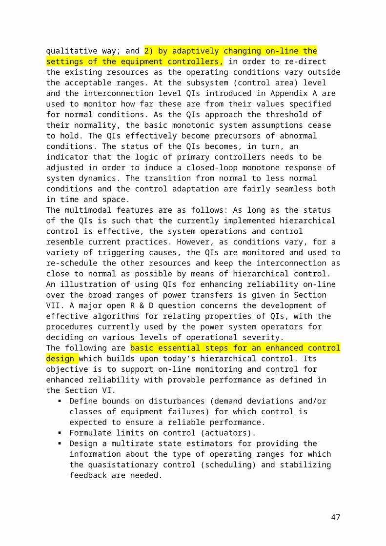
innately object-oriented in contrast to the hybrid approach of C++. Java also has several advanced capabilities for distributed programming, distributed middleware, and the World Wide Web, respectively, such as RMI, EJB, and Applets, which will be discussed later. A major milestone in the development of object technology was the creation of the Unified Modeling Language (UML) in 1996. UML is now the industry standard language for specifying, visualizing, constructing, and documenting the artifacts of software systems. It simplifies the complex process of software design, making a blueprint for construction.There is an international organization called the Object Management Group (OMG), supported by most vendors and dedicated to maximizing the portability, reusability, and interoperability of software using object technology. The Common Object Request Broker Architecture (CORBA) specification is the result of input from a wide range of OMG members, making its implementations the most generally applicable option. Microsoft’s DCOM, and the Sun Microsystems Remote Method Invocation (RMI) are examples of other models that enable software objects from different vendors, running on different machines, and on different operating systems, to work together.D. Component TechnologyObject-oriented programming in its early development has failed to meet expectations with respect to reusability. Component technologies build on the idea of providing third-party components that isolate and encapsulate specific functionalities [22], [23]. Components usually consist of multiple objects and this characteristic enables them to combine functionalities of the objects and offer them as a single software building block that can be adapted and reused without having to change them programmatically. The objective of the development of software components is to move toward a world in which components can be independently developed, assembled and deployed, like hardware. Reusable components are supposed to be plugged together in a distributed and inter-operable environment. Components vary in their granularity. A component can be very small, such as a simple GUI widget (e.g., a button), or it can implement an entire complex application, such as a state estimation. In the latter case, the application could be designed from scratch as a single component, a collection of components [24], or it could comprise a legacy application wrapped to conform to component interface standards. A component must provide a standard interface that enables other parts of the application to invoke its functions and to access and manipulate the data within the component. The structure of the interface is defined by the component model. The component model provides guidelines to create and implement components that can work together to form a larger application. A component builder should not have deal with implementation of multithreading, concurrency control, resource-pooling, security, and transaction management. Furthermore, if these services were implemented in each component, achieving true plug-and-play application assembly would be very difficult. A component model standardizes and automates the use of these services. The primary component models with wide acceptance within the software industry include: Enterprise JavaBeans (EJB), CORBA Components, and Microsoft COM/DCOM.Different models can be utilized to its greatest advantage of all available features of the underlying container and execution system to facilitate performance enhancement. Component adapters can be used to achieve to some degree the plug-and-play capability with different systems. XML Web Services, which will be discussed in Section VII, provide an Internet-based integration model for any-to-any integration and allow applications to communicate and share data over the Internet, regardless of operating system or programming language. They are like components.E. Middleware
47
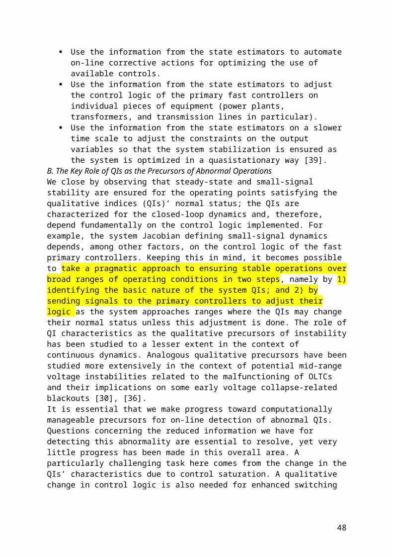
The objective of distributed object technology is to break complex applications into small components. Each component is in charge of a specific task and may run on a different machine in a network and all components may be seamlessly integrated into a common application. The need for interaction between the software objects led to the specification of middleware models to deal with communication between multiple objects that may reside on different network hosts. Middleware allows remote requests to invocate methods from objects located on other machines in the network [23].Middleware is responsible for providing transparency layers that deal with distributed systems complexities such as location of objects, heterogeneous hardware/software platforms, and different object implementation programming languages. Shielding the application developer from such complexities results in simpler design and implementation processes. Besides the core task of transparency of object invocations, some middleware technologies offer additional services to the application developer such as security, persistence, naming, and trading. Middleware provides generic interfaces for messaging, data access, transactions, etc. that enable applications and end users to interact with each other across a network. It represents a diverse group of software products that function as an integration, conversion, or translation layerIn essence, the term middleware denotes a set of general-purpose services that sits between platforms (various types of hardware and operating systems) and applications. A standardized interface allows applications to request services over the network without knowing how or even where the service is implemented. Middleware therefore facilitates the design of distributed systems whose configuration may dynamically change and where multiple applications implemented in different languages and running on different systems communicate with each other.There are four main classifications of middleware.• Transactional middleware—supports distributed synchronous transactions.• Message-oriented middleware—enables communication through messages.• Procedural middleware—primarily used in point-to point communication.• Object-oriented middleware—includes object-oriented concepts and supports messaging and transactions.F. CORBACORBA belongs to the object-oriented middleware classification. It is an open standard specifying a framework for transparent communication between applications and application objects [23], [25]. CORBA is a distributed object architecture that allows objects to interoperate across networks. A CORBA client asks for some services from an object, its request is transferred to the object request broker (ORB), which is responsible for forwarding the request to the right object implementation. This request contains all the information required to satisfy the request, such as target object, operations, parameters, etc. A client can request a service without knowing what servers are attached to the network. The various ORBs receive the requests, forward them to the appropriate servers, and then hand the results back to the client. Clients therefore never come in direct contact with the objects, but always with the interfaces of these objects (Fig. 7), which are determined through interface definition language (IDL). In addition, the communication of a client with an object running as a different process or on a different machine uses a communication protocol to portably render the data format independently from the ORB.
48

Interfejs ORBThe ORB provides a mechanism for transparently communicating client requests to target object implementations. The ORB simplifies distributed programming by decoupling the client from the details of the method invocations. This makes client requests appear to be local procedure calls. When a client invokes an operation, the ORB is responsible for finding the object implementation, transparently activating it if necessary, delivering the request to the object, and returning any response to the caller. The interfaces provided by ORB include domain-independent interfaces, such as the discovery of other available services, security, transactions, event notification, and other common facilities, and domain-specific interfaces that are oriented toward specific application domains, such as power systems, as well as nonstandard interfaces developed specifically for a given application.The ORB is the middleware that handles the communication details between the objects. CORBA is a mature technology suitable for tightly coupled transaction processing systems in high-volume applications within an enterprise.G. Agents TechnologyAgent technology is an extension of object technology. An agent is a software entity that is situated in some environment and can sense and react to changes in that environment [26]. Agents do not just act in response to changes that have occurred in their environment, they have their own goals and also can initiate action to achieve them, i.e., an agent is capable of independent action on behalf of its user or owner. In other words, an agent can figure out for itself what it needs to do in order to satisfy its design objectives, rather than being explicitly told what to do at any given moment. Agents are loosely coupled and can communicate via messaging. New functions can easily be added to an agent-based system by creating a new agent, which will then make its capabilities available to others. A multiagent system is one that consists of a number of agents which interact with one another, typically by exchanging messages through some computer network infrastructure. Tasks are carried out by interacting agents that can cooperate with each other. Agents are thus required to cooperate, coordinate and negotiate with each other. The agent technology makes it possible to build extensible and flexible distributed cooperation systems.H. Industry EffortsEPRI has been leading the power industry in standardizing communication protocols and data models. The Utility Communication Architecture (UCA) launched in the late 1980s was an attempt to define a set of comprehensive communication protocols based on the OSI reference model for use in electric utilities. Notable success out of that effort is the ICCP mentioned in Section V-A, which became an IEC standard (IEC TASE-2) for communications among control centers. For effective communication, the protocol is only one aspect; the semantics of the data to be exchanged is just as important. The Common Information Model (CIM) [27]–[29], again led by EPRI, is to specify common semantics for power system resources (e.g., a substation, a switch, or a transformer) used in EMS, their attributes and relationships and is described in the UML in recognition of object-oriented component technology. The objective of CIM is to support the integration of independently developed applications between vendor-
49

specific EMS systems, or between an EMS system and other systems that are related to EMS operation, such as generation or distribution management. CIM has been extended to support exchange of market information both within and between ISOs and RTOs. The CIM market extension is called CME, and it expedites e-transactions and market performance measurement. XML for CIM model exchange has been developed [30].CIM together with component interface specification (CIS) forms the core of EPRI’s Control Center Application Programming Interface (CCAPI) project. CIM defines the essential structure of a power system model whereas CIS specifies the component interfaces. CCAPI has since been adopted as an IEC standard: the IEC 61 970 (Energy Management System Application Programming Interface) [31]. IEC 61 970 normalizes a set of application programming interfaces (APIs) for the manipulation of both real-time critical and near real-time EMS/SCADA data, as well as a data model and a configuration data exchange format. Other IEC standards [32] that are relevant to control center operation are IEC 61 968 (System Interfaces for Distribution Management) and IEC 61 850 (Communication Networks and Systems in Substations). IEC 61 968 extends the IEC 61 970 model for both modeling and APIs to distribution management systems. The APIs are meant for inter-application messaging at the enterprise level. IEC 61 850 primarily specifies abstract communication service interfaces (ACSI) and their mappings to concrete protocols, but it also defines an elaborate data model and configuration data exchange format, independent of CIM.VI. MODERN DISTRIBUTED CONTROL CENTERSThe term “distributed control center” was used in the past to refer to the control center whose applications are distributed among a number of computers in a LAN [33]. By that standard almost all control centers today that are equipped with distributed processing capability in a networked environment would be called “distributed.” That definition is too loose. On the other hand, if a control center that is fully decentralized, integrated, flexible, and open, as the Grid services-based future control center to be described in Section VIII-C, is counted as a distributed control center, the definition is perhaps too stringent. We adopt the definition of the distributed system in Section V-B to control centers and call it a distributed control center if it comprises of a set of independent computers that appears to the user as a single coherent system. A distributed control center typically has some or all of its data acquisition and data processing functions distributed among independent computers and its EMS and BMS applications also distributed. It utilizes the distributed system technologies to achieve some level of decentralization, integration, flexibility, and openness: the characteristics that is desirable in today’s power system operating environment.Current trends in the development of distributed control centers from the previous multicomputer networked system to a flexible and open system with independent computers are moving in the following directions:• separation of SCADA, EMS, and BMS;• IP-based distributed SCADA;• standard (CIM)-based distributed data processing;• middleware-based distributed EMS and BMS applications.The data acquisition part of SCADA handles real-time data, and is very transaction-intensive. The applications in EMS involve mostly complex engineering calculations and are very computation-intensive. These two dissimilar systems are tightly bundled together in a conventional control center because proprietary data models and databases are used due to historical reasons. With proprietary data models and database management systems to handle data, such data could not be easily exchanged, and it prevents effective use of third-party application software. A separate SCADA system and EMS system would serve a control center better by expediting the exploitation of new technologies to achieve the goals of
50

decentralization, integration, flexibility, and openness. The separation of SCADA and EMS is a logical thing to do.The SCADA function in a conventional control center starts with the RTUs collecting data from substations and, after simple local processing (e.g., data smoothing and protocol specification), the data is then sent through a dedicated communication channel with proprietary protocol to the appropriate data acquisition computer in the control center where a TCP/IP based computer network is used.An interface is therefore needed. The data acquisition computer converts the data and prepares it for deposition in the real-time database. The real-time database is accessed and used by various applications. For reasons of efficiency, the interface may be handled by a telecontrol gateway, and more gateways may be used in a control center. The location of the gateway may move to the substation if standard IP protocol is used. The gateway is then connected to the control center. If the RTU is TCP/IP based, it can be connected directly to the control center resulting in a distributed data acquisition system. In this way, the gateway serves as a data concentrator and communication processor (Fig. 8). RTUs or IEDs may be connected to a data concentrator or connected directly to the control center [34].
The use of fixed dedicated communication channels from RTUs to control center leaves no flexibility in RTU-control center relationship which was not a problem in the past. When, for example, another control center requires real-time data from a particular substation not in the original design, there are only two ways to do it. In the first case, the other control center has to acquire the data through the control center to which the RTU is attached. In the second case, a new dedicated channel has to be installed from the RTU to the other control center.The dedicated channels with proprietary protocols for SCADA were developed for reasons of speed and security [35], [36]. Communication technologies have advanced tremendously in the last couple of decades in both hardware and software, resulting in orders of magnitude increase in transmission speed and sophistication in security protection. Modern communication channels with metallic or optical cables have enormous bandwidths compared to the traditional 9600 kb/s or less available for RTU communications. Responsibility to guarantee timely delivery of specific data in a shared communication network such as intranet or Internet falls to the QoS function of communication network management and is accomplished through protocols for resource allocation. With further advancement in QoS, more and more stringent real-time data requirements may be handled through standard protocols. Network security involves several issues: confidentiality, integrity, authentication, and nonrepudiation. Cryptography is used to ensure confidentiality and integrity, so that the
51

information is not available to and can not be created or modified by unauthorized parties. Digital hash is used for authentication and digital signature for nonrepudiation. Network security has advanced rapidly in recent years [37].There is no reason that the new SCADA communications should not be using standard protocols such as IP-based protocols. Indeed, inability of SCADA to take advantage of recent progress in cyber security is considered a serious security risk by today’s standards [38]. SCADA should be IP-based and liberated from dedicated lines by tapping into an available enterprise WAN or as a minimum use Internet technology to enable the use of heterogeneous components. In the future, as Internet QoS performance and encryption protocols improve, there will be little difference between a private-line network and virtual private network (VPN) on the Internet when standard protocols are used. A VPN is a network that is constructed by using public wires to connect nodes. The system uses encryption and other security mechanisms to ensure that only authorized users can access the network and that the data cannot be intercepted. VPN can be used to augment a private-line enterprise network when a dedicated facility can not be justified. In other words, the physical media and the facilities used for the network will become less of a concern in a control center when standard protocols are used.If standard communication protocols are used, a control center (i.e., its application software) may take data input from data concentrators situated either inside or outside its territory.The only difference between data from an internal data concentrator or an external one is the physical layer of the communication channel. The former may be through the intranet and the latter needs special arrangement for a communication channel [38], [40] (Fig. 9).
With IP-based distributed SCADA that uses standard data models, data can be collected and processed locally before serving the applications. Again using standard data models, databases can also be distributed. Search engines may be utilized for fast and easy access to relevant information. Intelligent agents with learning capability may be deployed for data management and data delivery.Once the data is deposited in the real-time database, it can be used by various applications to serve the required functions of EMS or BMS. The output of an application may be used by another application. As long as an application has access through the network to the database with sufficient speed and ensured security, the physical location of the application server and the data will be of little concern. The network should be capable of hosting any kind of applications and supporting intelligent information gathering through it [41]. Component and middleware technologies enable such distributed architecture.Present-day control centers are mostly provided with CIM data models and middleware that allow distributed applications within the control center. Only a few of them use CIM-based data models and middleware-based applications as their platforms. Specific applications of
52

distributed technologies include Java [42], component technology [43], [44], middleware-based distributed systems [45], CORBA [46], [47], and agent technology [48], [49].A comprehensive autonomous distributed approach to power system operation is proposed [24]. Deployment of agents responsible for specific temporally coordinated actions at specific hierarchical levels and locations of the power system is expected to provide the degree of robust operation necessary for realizing a self-healing grid [13].VII. EMERGING TECHNOLOGIESThe information and communication technologies have converged into Grid services that are based on Web services and Grid computing. Future control centers should embrace this development and build an infrastructure on Grid services. In this section, we introduce the service-oriented architecture, Web services and Grid computing. A. Service-Oriented Architecture (SOA) SOA has evolved over the last ten years to support high performance, scalability, reliability, and availability in computing. Applications have been designed as services that run on a cluster of centralized servers. A service is an application that can be accessed through a programmable interface. With that definition, an agent can be viewed as providing a service. The service concept is a generalization of the component concept. The following figure depicts the conceptual roles and operations of a SOA. The three basic roles are the service provider, the service consumer, and a service broker.A service provider makes the service available and publishes the contract that describes its interface. It then registers the service with a service broker. A service consumer queries the service broker and finds a compatible service. The service broker then gives the service consumer directions regarding where to find the service and its service contract. The service consumer uses the contract to bind the client to the server (Fig. 10).
Most standard distributed computing systems implement a SOA. For example, clients may access SOA services using a middleware, such as DCOM, CORBA, or RMI. ORB in CORBA functions as a service broker (Section V-F). While these tightly coupled protocols are very effective for building a specific application, their flexibility in the reusability of the system is still limited, compared to Web services, to be introduced below, that have evolved from such systems. Because they are not fully independent of vendor implementations, platforms, languages, and data encoding schemes, SOA based on middleware has limitation on interoperability as well.B. Web ServicesWeb services [50], [51] are a particular type of SOA that operates effectively over the Web using XML-based protocols. Web services enable interoperability via a set of open standards to provide information about the data in a document to users on various platforms.Web services are built on service-oriented architecture, Internet/intranet technologies, and other technologies like information security. The core components of Web services consist of:
53
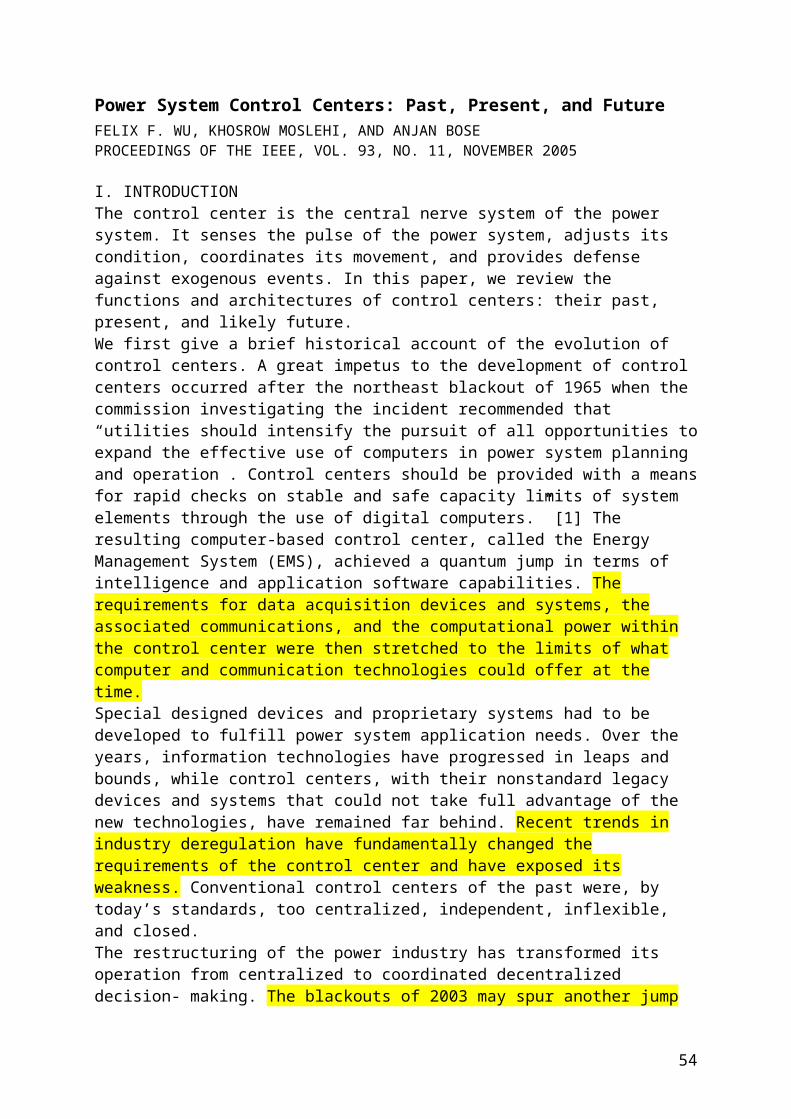
• Simple Object Access Protocol (SOAP) for cross-platform inter-application communication;• Web Services Description Language (WSDL) for the description of services;• Universal Description, Discovery, and Integration protocol (UDDI) for finding available Web services on the Internet or corporate networks.
Web service providers describe their services using WSDL (Fig. 11) and register with UDDI registry. UDDI can point to services provided by service providers and obtain descriptions through WSDL. For a service client, a typical invoking process would be the following:• locate a Web service that meets the requirements through UDDI;• obtain that Web service’s WSDL description;• establish the link with the service provider through SOAP and communications with XML messages.The Web services architecture takes all the best features of the service-oriented architecture and combines it with the Web. The Web supports universal communication using loosely coupled connections. Web protocols are completely vendor-, platform-, and language-independent. Web services support Web-based access, easy integration, and service reusability. With Web service architecture, everything is a service, encapsulating behavior and providing the behavior through an interface that can be invoked for use by other services on the network. Services are self-contained, modular applications that can be described, published, located, and invoked over the Internet. Promises of Web services for power system applications have been pointed out [52]–[55].C. Grid Computing and Grid ServicesOnline power system dynamic analysis and control for future control centers will demand computational power beyond what is currently available. It also requires distribution of intelligence at all hierarchical levels of the power grid to enable sub-second coordinated intelligent control actions (Section VIII-B). In future control centers, applications need to be more intelligent and computation needs to be more intelligent too. In this subsection, we look at recent progress and future promises in distributed computing that facilitate distributed intelligence and fast computing. In recent years, progress has been made in distributed high-performance computing. High-performance computing, traditionally called supercomputing, is built on different, but co-located processors. It is expensive and used by only special customers for special purposes. Cluster computing is based on clusters of high-performance and massively parallel computers built primarily out of commodity hardware components. It is popular and has been applied to control centers.There is a new paradigm, called Grid computing [56]–[58], that has emerged out of cluster computing. It is a clustering of a wide variety of geographically distributed resources (computer CPUs and memories) to be used as a unified resource, yet it provides seamless access to and interaction among these distributed resources, applications and data. A virtual
54
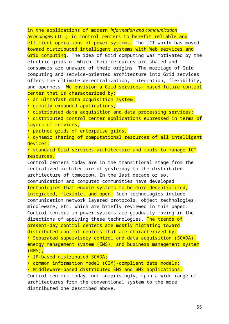
organization is formed when an application is invoked. This new paradigm is built on the concept of services in the service-oriented architecture. However, Grid computing has generalized the concept of software services to resources. In other words, resources in Grid computing are provided as services. Grid computing renders Grids resources and Grid applications to consist of dynamically composed services.The motivation and the vision of Grid computing are to develop:• a world in which computational power (resources, services, data) is as readily available as electrical power and other utilities, in which computational services make this power available to users;• in which these services can interact to perform specified tasks efficiently and securely with minimal human intervention.More specifically, the idea of grid computing is to provide:• universal access to computing resources;• seamless global aggregation of resources;• seamless composition of services.To enable the aggregation of geographically distributed resources in grid computing, protocols and mechanisms to secure discovery of, access to, and aggregation of resources for the realization of virtual organizations and the development of applications that can exploit such an aggregated execution environment are necessary. In 1996 the Advanced Research Projects Agency (ARPA) launched the successful Globus Project with the objective to create foundation tools for distributed computing. The goal was to build a system that would provide support for resource discovery, resource composition, data access, authentication, authorization, etc. Grid computing is making progress to become a practical reality. And it is the future to come.Advocates of Grid computing are pushing for the grand vision of global grids over the Internet. The other extreme, however, is the cluster grids of small managed computer cluster environments that are popularly employed today. In between, we may view various sub-grids of the Global grid in Grid computing as consisting of:• enterprise grids;• partner grids.
Fig. 12. Enterprise grids and partner grids.Enterprise grids are meant for multilocation enterprises to share their resources. Partner grids are extensions of enterprise grids to facilitate collaboration and access to share resources between sister organizations (Fig. 12). They are of particular interest in the context of control centers. Grid service is a convergence of Grid computing and Web services. Grid services offer dependable, consistent, and pervasive access to resources irrespective of their different physical locations or heterogeneity, using open standard data formats and transport protocols. Grid services can be viewed as an extension of Web services. A standard called Open Grid Services Infrastructure (OGSI) was developed using this approach. Globus Toolkit 3.2 (GT3.2) is a software toolkit based on OGSI that can be used to program Grid-based
55
applications. Another standard, the Web Services Resource Framework (WSRF), was presented in 2004, to substitute OGSI. WSRF aims to integrate itself into the family of Web services. Globus Toolkit 4 (GT4) is a full implementation of WSRF [59].D. Web and Grid Services SecuritySecurity has become a primary concern for all enterprises exposing sensitive data and business processes through a shared environment. In fact, the biggest obstacle to wider adoption of Web services today has been the security concern. It is thus important for Web services and Grid services to have impermeable security mechanisms. Web services security has several dimensions: it requires authentication (establishing identity), authorization (establishing what a user is allowed to do), confidentiality (ensuring that only the intended recipient can read the message), and integrity (ensuring the message has not been tempered with). Encryption and digital signatures are the means to accomplish cyber security. We mentioned in what follows several recent developments in Web services security [60] Security is obviously one of the most challenging aspects of Grid computing and great progress is being made [61].Security assertion markup language (SAML), developed by OASIS, defines security-related schemas for structuring documents that include information related to user identity and access or authorization rights. By defining how this information is exchanged, SAML lets companies with different internal security architectures communicate. It functions as a framework for exchanging authentication, attribute, and authorization assertions across multiple participants over the Internet using protocols such as HTTP and SOAP. SAML can also indicate the authentication method that must be used with a message, such as a password, Kerberos authentication ticket, hardware token, or X.509 digital certificate. Another development is the Web Services Security Protocol (WSSec), developed by IBM and Microsoft, that let applications attach security data to the headers of SOAP messages. It can include security algorithm metadata that describe the process for encrypting and representing encrypted data and define syntax and processing rules for representing digital signatures. It is under consideration as a standard by OASIS. Traditional network firewalls are not suitable for Web services because they have no way of comprehending the messages crossing their posts. Other traditional security techniques, such as virtual private networks or secure sockets layer (SSL) technology, can not secure the large number of transactions of Web services. XML firewall has been developed to intercept incomingXMLtraffic and take actions based on the content of that traffic.VIII. FUTURE CONTROL CENTERSFuture control centers, as we envision, will have much expanded applications both in power system operations and business operations based on data that are collected in a much wider and faster scale. The infrastructure of the control center will consist of large number of computers and embedded processors (e.g., IEDs) scattered throughout the system, and a flexible communication network in which computers and embedded processors interact with each other using standard interfaces. The data and data processing, as well as applications, will be distributed and allow local and global cooperative processing. It will be a distributed system where locations of hardware, software, and data are transparent to the user.The information technology has evolved from objects, components, to middleware to facilitate the development of distributed systems that are decentralized, integrated, flexible, and open. Although significant progress has been made, it is still not fully distributed. Today’s middleware is somewhat tightly coupled. For example, the ORB in CORBA, which provides interface between objects, is not fully interoperable. Recent progress in the ease and popularity with XML-based protocols in Internet applications has prompted the development of the Web services architecture, which is a vital step toward the creation of a fully distributed system. The concept of services represents a new paradigm.
56
A software service was originally defined as an application that can be accessed through a programmable interface. Services are dynamically composed and distributed, and can be located, utilized, and shared. The developers in Grid computing have extended the concept of service from software to resources such as CPU, memory, etc. Resources in Grid computing can be dynamically composed and distributed, and can be located, utilized, and shared. Computing, as a resource service, is thus distributed and shared. The idea of service-oriented architecture, Grid computing and open standards should be embraced for adoptions not only in future control centers, but also in other power system functions involving information and communication technologies.In a Grid services environment, data and application services, as well as resource services, are distributed throughout the system. The physical location of these services will be of little concern. It is the design of the specific function in an enterprise that dictates how various services are utilized to achieve a specific goal. The control center function, i.e., to ensure the reliability of power system operation and to manage the efficient operation of the market, represents one such function in the enterprise. In this new environment, the physical boundary of any enterprise function, such as the control center, may no longer be important and indeed become fuzzy. It is the collective functionality of the applications that represents the control center makes it a distinct entity.Grid services-based future control centers will have distributed data services and application services developed to fulfill the role of control centers in enhancing operational reliability and efficiency of power systems. Data service will provide just-in-time delivery of information to applications that perform functions for power system control or business management. The computer and communication infrastructure of future control centers should adopt standard Grid services for management of the resources scattered around the computers and embedded processors in the power system to support the data and application services.The concepts we just brought up about future control centers: extended data acquisition, expanded applications, Web services, Grid computing, etc., will be elaborated in more details in the remaining subsections.A. Data AcquisitionFor power system reliability, the security monitoring and control function of the control center is actually the second line of defense. The first line of defense is provided by the protective relay system. For example, when a fault in the form of a short circuit on a transmission line or a bus occurs, measurement devices such as a current transformer (CT) or potential transformer (PT) pick up the information and send it to a relay to initiate the tripping (i.e., opening) of the appropriate circuit breaker or breakers to isolate the fault. The protective relay system acts in a matter of one or two cycles (one cycle is 1/60 of a second in a 60-Hz system). The operation of the protective relay system is based on local measurements.The operation of security monitoring and control in a control center, on the other hand, is based on system-wide (or wide-area) measurements every 2 s or so from the SCADA system. The state estimator in EMS then provides a snapshot of the whole system. Different time scales driving the separate and independent actions by the protective system and the control center lead to an information and control gap between the two. This gap has contributed to the missed opportunity in preventing cascading outages, such as the North American blackout and the Italian blackout of 2003. In both cases, protective relays operated according to their designs by responding to local measurement, whereas the control center did not have the system-wide overall picture of events unfolding.During that period of more than half an hour, control actions could have been taken to save the system from a large-scale blackout.The security monitoring and control functions of today’s control center, such as state estimation, contingency analysis, etc., are based on steady-state models of the power system.
57
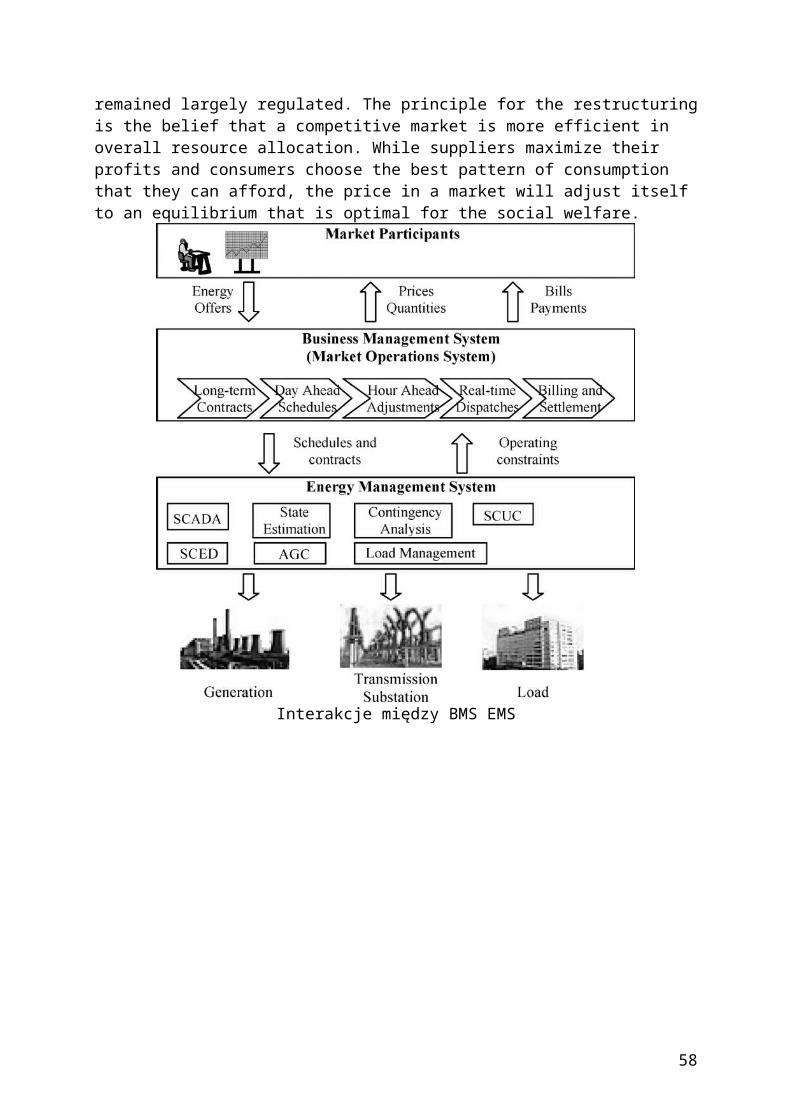
There is no representation of system dynamics that govern the stability of a system after a fault in control center’s advanced application software. The design philosophy for security control is that of preventive control, i.e., changing system operating conditions before a fault happens to ensure the system can withstand the fault. There is no analytical tool for emergency control by a system operator in a control center. All of these are the result of limitations imposed by: 1) the data acquisition system and 2) computational power in conventional control centers. The issue of computational power has already been addressed by Grid computing in Section VII-C. We will discuss the issue of measurement system in what follows.Although RTUs, IEDs, and substation control systems (SCSs) in substations sample power measurements in a granularity finer than a second, SCADA collects and reports data (by exception) only in the interval of several seconds. The system-wide measurements, strictly speaking, are not really synchronized, but their differences are in the order of the time-scale of the window of data collection, which is approximately 2 s. But because the model is a steady-state model of the power system, such a discrepancy is tolerated.As mentioned earlier, the bandwidth limitation problem in SCADA is a legacy problem from the past. Future communication networks for SCADA using WAN will have much wider bandwidth and will be able to transmit measurement data in finer resolutions. However, the data needs to be synchronized. This can be done by using synchronization signals from the global positioning system (GPS) via satellites. Modern GPS-based phasor measurement units (PMU) [62] are deployed in many power systems to measure current and voltage phasors and phase angle differences in real time. GPS in PMU provides a time-tagged one pulse-per-second (pps) signal which is typically divided by a phase-locked oscillator into the required number of pulses per second for sampling of the analog measurements. In most systems being used at present, this is 12 times per cycle or 1.4 ms in a 60-Hz system. In principle, system-wide synchronous data in the order of milliseconds or even finer can be collected by PMU-like devices in the future to be used for monitoring system dynamic behavior. PMUs and the future generation of PMU-class data acquisition devices can augment existing RTUs, IEDs, and SCSs to provide a complete picture of power system dynamical conditions and close the gap between today’s protective relay operations and control center functions.The electricity market is a new experiment. As the market matures and our understanding of market operation strengthens, new measurement requirements and devices, and new market information or data acquisition systems that will ensure an efficient and fair market will definitely emerge. Real-time measurements are needed and techniques should be developed for market surveillance to mitigate market power and for enforcement of contract compliance. Real-time data, properly collected and judiciously shared, can also assist regional cooperation, such as regional relay coordination or regional transmission planning among interconnected systems, that benefits all parties involved [8].B. FunctionsMarket functions of a control center will expand once new measurement systems are available and our understanding of market behavior increases. We mentioned market surveillance and contract compliance and there will be more in the future. On the power system operation side, the new data acquisition systems, such as PMUs that provide measurements in the order of milliseconds, offer new opportunities for dynamic security assessment and emergency control that would greatly enhance system reliability. A great deal of research has already begun along these directions.Current control centers provide analysis and control of power systems based on the steady-state models of the power system. For system dynamic effects, such as transient stability, the approach has always been to conduct simulation studies based on postulated future conditions
58
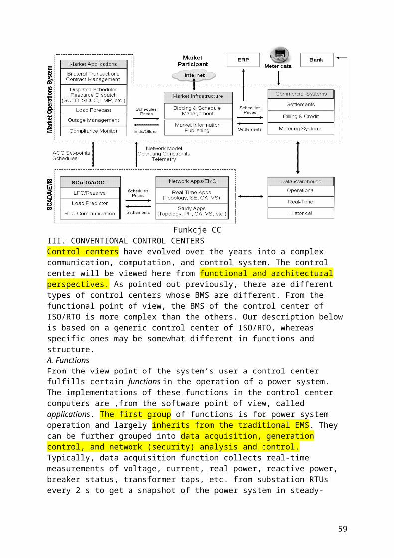
and the results are used to design protective system response and to set operational limits on transmission lines and other apparatuses.This approach is becoming more and more difficult to continue due to increasing uncertainty in system operation conditions in the market environment. Online monitoring and analysis of power system dynamics using real-time data several times a cycle will make it possible for appropriate control actions to mitigate transient stability problems in a more effective and efficient fashion [63]. Other system dynamic performance, including voltage stability and frequency stability, can also be improved with the assistance of PMUs [64]–[66]. A comprehensive “self-healing power grid” framework for coordinating information and control actions over multiple time-scales ranging from milliseconds to an hour employing distributed autonomous intelligent agents has been defined in [13].Another function in control centers that has developed rapidly in the last couple of years and will become even more important in the future is the visualization tools [67], [68] to assist power system operators to quickly comprehend the “big picture” of the system operating condition. As technology progresses, more and more data will become available in real time. The human-machine aspect of making useful information out of such data in graphics to assist operators comprehend the fast changing conditions easily and timely and be able to respond effectively is crucial in a complex system such as the power system as long as human operators are still involved.Developing new functions to utilize enhanced data acquisition systems to greatly improve power system reliability and efficiency will be a great challenge to the research community. Successful research results will be valuable in bringing power system operations to a new level of reliability and efficiency.C. Grid Services-Based Future Control CentersA future Grid service-based control center will be an ultimate distributed control center that is decentralized, integrated, flexible, and open. In a Grid-service environment, everything is a service. Future control centers will have data services provided throughout the power system. Data acquisition services collect and timestamp the data, validate and normalize them, and then make it available. Data processing services process data from various sources for deposition into databases or high level applications. Applications will call data services and data will be delivered just in-time for critical applications. Various functions serving the needs of control centers are carried out as application services.
59
Usługi aplikacyjne centrów sterowaniaTraditional applications, such as contingency analysis, congestion management, may be further decomposed into their constituent components, for example, power flows, OPF, etc. Application services may have different granularity and may rely on other services to accomplish its job (Fig. 13). Data and application services are distributed over the Grids. TheGrids can use the intranet/Internet infrastructure in which sub-networks are formed for different companies (enterprise grids) with relatively loose connection among cooperative companies (partner grid). The computer and communication resources in the Grids are provided and managed by the standard resource services that deliver distributed computing and communication needs of the data and application services.The designer of control centers develops data and application services, and no longer needs to be concerned with the details of implementation, such as the location of resources and information security, provided the services are properly registered in the Grid environment. The new business model is that the software vendors will be service providers and power companies as service integrators. Power companies focus on information consumption and vendors focus on software manufacturing, maintenance, and upgrading. Computer and communication infrastructure will be left to the ICT professionals.This clear separation of responsibility would simplify and accelerate the delivery of new technology. We envision future control centers based on the concept of Grid services include among others the following features:• an ultrafast data acquisition system;• greatly expanded applications;• a partner grid of enterprise grids;• dynamic sharing of computational resources of all intelligent devices;• use of service-oriented architecture;• distributed data acquisition and data processing services;• distributed control center applications expressed in terms of layers of services;• use of standard Grid services architecture and tools to manage ICT resources.IX. CONCLUSIONA control center uses real-time data to support the operation of a power system to ensure a high level of reliability and an efficient operation of the market. In this paper, we have briefly reviewed the evolution of control centers from its past to present. An elementary tutorial on the enabling technologies, from object to middleware technologies that help in making today’s control centers more decentralized, integrated, flexible, and open is included. The power industry is catching up in the application of the latest ICTs to control centers. With the rise of the Internet age, the trend in ICT is moving toward Grid services. The introduction of PMUs, on the other hand, may usher in a new generation of data acquisition systems and enabling of more advance applications in controlling dynamic performance of power systems in real time. We have attempted to outline a development direction for future control centers utilizing Grid services architecture.Control centers involve extremely complex systems with intricate linkages of hardware, software, and devices. The presentation of this paper aims to simplify a great deal of the complex issues involved in implementation for the sake of conceptual clarity. Every step in the implementation is a challenge. However, challenges should not deter us from taking actions for change. The more we resist change to revamp the monstrous complex system today, the more difficult it will become to take advantage of technology advancement to improve power system operations in the future. By not tapping into the mainstream of the ICT, the maintenance cost of the custom system will eventually outweigh the investment cost of new technologies.
60
The focus of this paper has been on the technology and the closing of the technology gap between power system control centers and ICT. Closing the gap in technology is relatively easier compared to another gap we would like to highlight here before the closure. This is the gap between applications and technology. The promises of new data acquisition devices and systems, Grid computing and boundless-bandwidth communications offer tremendous opportunities in the development of new functions and new approaches to improve power system reliability and efficiency. The advances in research into innovative theories and methods to effectively utilize new technologies are much slower than the technology advancement itself. Approaches and methodologies for power system analysis and control have changed very little in the past few decades despite of the fast changes in technology and environments. Technology gaps can be closed by materials supplied by hardware, software and devices. Application gap can only be closed by visions powered by brains. Human resource development should be high on the agenda for the leaders of the community for this purpose.References
[1] U.S. Federal Energy Commission, “Final report on 1965 blackout,” July 19, 1967. [2] T. E. Dy-Liacco, “Control centers are here to stay,” IEEE Comput. App. Power, vol. 15, no. 4, pp. 18–23, Oct. 2002. [3] F. F. Wu, “Real-time network security monitoring, assessment and optimization,” Elect. Power Energy Syst., vol. 10, pp. 83–100, Apr. 1988. [4] F. F. Wu and R. D. Masiello, Eds., “Computers in power system operation,” Proc. IEEE (Special Issue), vol. 75, no. 12, Dec. 1987. [5] T. E. Dy-Liacco, “Modern control centers and computer networking,” IEEE Comput. App. Power, vol. 7, pp. 17–22, Oct. 1994. [6] P. Joskow, “Restructuring, competition and regulatory reform in the U.S. electricity sector,” J. Econ. Perspectives, vol. 11, no. 3, pp. 119–138, 1997. [7] M. Kezunovic, T. Djoki, and T. Kosti, “Automated monitoring and control using new data integration paradigm,” in Proc. 38th Annu. Hawaii Int. Conf. System Sciences 2005, p. 66a. [8] F. Maghsoodlou, R. Masiello, and T. Ray, “Energy management systems,” IEEE Power Energy, vol. 2, no. 5, pp. 49–57, Sep.–Oct. 2004. [9] A. F. Vojdani, “Tools for real-time business integration and collaboration,” IEEE Trans. Power Syst., vol. 18, pp. 555–562, May 2003. [10] N. Peterson, T. A. Green, and A. deVos, “Enterprise integration via data federation,” presented at the DA/DSM DistribuTECH Europe 99 Conf., Madrid, Spain, 1999. [11] D. Amor, The E-Business Revolution. Upper Saddle River, NJ: Prentice Hall PTR, 2000. [12] M. Jacke, M. Lenzerini, Y. Vassilion, and P. Vassiliadis, Fundamentals of Data Warehouses, 2nd ed. New York: Springer, 1998. [13] K. Moslehi, A. B. R. Kumar, D. Shurtleff, M. Laufenberg, A. Bose, and P. Hirsch, “Framework for a self-healing power grid,” presented at the 2005 IEEE PES General Meeting, San Francisco, CA, 2005. [14] G. P. Azevedo and A. L. Oliveira Filho, “Control centers with open architectures,” IEEE Comput. App. Power, vol. 14, no. 4, pp. 27–32, Oct. 2001. [15] J. Walrand and P. Varaiya, High-Performance Communication Networks. San Francisco, CA: Morgan Kaufmann, 1996. [16] D. J. Marihart, “Communications technology guidelines for EMS/ SCADA systems,” IEEE Trans. Power Del., vol. 16, no. 2, pp. 181–188, Apr. 2001. [17] Extensible Markup Language (XML) W3C [Online]. Available: http://www.w3.org/xml [18] K. Tomsovic, D. Bakken, V. Vankatasubramanian, and A. Bose, “Designing the next generation of real-time control, communication and computations for large power systems,” Proc. IEEE (Special Issue on Energy Infrastructure Systems), vol. 93, no. 5, pp. 964–965, May 2005. [19] C. C. Liu, J. Jung, G. T. Heydt, V. Vittal, and A. G. Phadke, “The strategic power infrastructure defiense (SPID) system,” IEEE Control Syst. Mag., vol. 20, no. 4, pp. 40–52, Aug. 2000.
61
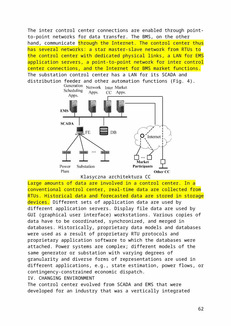
[20] A. S. Tanenbaum and M. V. Steen, Distributed Systems: Principles and Paradigms. Upper Saddle River, NJ: Prentice-Hall, 2002. [21] Object FAQ [Online]. Available: http://www.objectfaq.com/ oofaq2/body/basics.htm [22] W. Emmerich and N. Kaveh, “Component technologies: Java Beans, COM, CORBA, RMI, EJB and the component model,” in Proc. 24th Int. Conf. Software Engineering (ICSE) 2002, pp. 691–692. [23] W. Emmerich, Engineering Distributed Objects. New York: Wiley, 2000. [24] K. Moslehi, A. B. R. Kumar, E. Dehdashti, P. Hirsch, and W. Wu, “Distributed autonomous real-time system for power system operations—a conceptual overview,” presented at the IEEE PES Power System Conf. Exhibition, New York, 2004. [25] Object Management Group [Online]. Available: http://www. omg.com [26] ,M. Klusch, Ed., Intelligent Information Agents Berlin, Germany: Springer, 1999. [27] “Final Report, Common Information Model (CIM): CIM 10 Version,” Nov. 2001. [28] D. Becker, H. Falk, J. Billerman, S. Mauser, R. Podmore, and L. Schneberger, “Standards-based approach integrates utility applications,” IEEE Comput. App. Power, vol. 14, no. 4, pp. 13–20, Oct. 2000. [29] J. P. Britton and A. N. deVos, “CIM-based standards and CIM evolution,” IEEE Trans. Power Syst., vol. 20, no. 2, pp. 758–764, May 2005. [30] A. deVos, S. E. Widergren, and J. Zhu, “XML for CIM model exchange,” in IEEE Proc. Power Industry Computer Applications 2000, pp. 31–37. [31] Energy Management System Application Programming Interface (EMS-API), Draft IEC Standard , IEC 61 970, Oct. 2002 [Online]. Available: ftp://epriapi.kemaconsulting.com/downloads [32] C. Hoga and G. Wong, “IEC 61 850: open communication in practice in substations,” in Proc. IEEE PES 2004 2004, vol. 2, pp. 618–623. [33] L. Murphy and F. F. Wu, “An open design approach for distributed energy management systems,” IEEE Trans. Power Syst., vol. 8, no. 3, pp. 1172–1179, Aug. 1993. [34] G. Daniëls, G. Beilßer, and B. Engel, “New tools to observe and control large networks,” presented at the CIGRE Session 2002, Paris, France. [35] C. H. Hauser, D. E. Bakken, and A. Bose, “A failure to communicate,” IEEE Power Energy, vol. 3, no. 2, pp. 47–55, Mar.–Apr. 2005. [36] B. Qiu, Y. L. Liu, and A. G. Phadke, “Communication infrastructure design for strategic power infrastructure defence (SPID) system,” in Proc. IEEE Power Engineering Soc. Winter Meeting 2002, vol. 1, pp. 672–677. [37] C. Landwehr, “Computer security,” Int. J. Inf. Security, vol. 1, pp. 3–13, Aug. 2001. [38] J. E. Dagle, S. E. Widergren, and J. M. Johnson, “Enhancing the security of supervisory control and data acquisition (SCADA) systems: the lifeblood of modern energy infrastructures,” in Proc. IEEE Power Engineering Soc. Winter Meeting 2002, vol. 1, p. 635. [39] H. Hayashi, Y. Takabayashi, H. Tsuji, and M. Oka, “Rapidly increasing application of intranet technologies for SCADA,” in Proc. IEEE T&D Conf. Exhibition: Asia Pacific 2002, vol. 1, pp. 22–25. [40] J. Corera, J. Martí, J. Arriola, W. Lex, A. Kuhlmann, and W. Schmitz, “New SCADA/DMS/EMS integrated control system architecture for Iberdrola,” in CIGRE Session 2002 Paris, France. [41] A. Diu and L. Wehenkel, “EXaMINE—experimentation of a monitoring and control system for managing vulnerabilities of the European infrastructure for electrical power exchange,” in Proc. IEEE Power Engineering Soc. Summer Meeting 2002, vol. 3, pp. 1410–1415. [42] X. P. Wu, Y. Zhang, and X. W. Wang, “A new generation EMS,” in IEEE Proc. PowerCon Int. Conf. 2002, vol. 1, pp. 190–194. [43] X. B. Qiu and W. Wimmer, “Applying object-orientation and component technology to architecture design of power system monitoring,” in Proc. PowerCon International Conf. 2000, vol. 2, pp. 589–594. [44] X. L. Li, M. Y. Gao, J. S. Liu, Z. H. Ding, and X. Z. Duan, “A software architecture for integrative utility management system,” in Proc. IEEE Power Engineering Soc. Winter Meeting 2001, vol. 2, pp. 476–480. [45] K. Kawata, T. Yamashita, Y. Takahata, and M. Ueda, “A largescale distributed control system on multi-vendor platform,” in Proc. IEEE T&D Conf. Exhibition: Asia Pacific Oct. 2002, vol. 1, pp. 37–42.
62
[46] X. L. Li, D. Y. Shi, Z. H. Ding, X. Z. Duan, M. Y. Gao, and Y. Z. He, “Study on MAS architecture of EMS,” in Chinese, Autom. Elect. Power Syst., vol. 25, pp. 36–40, Jun. 2001. [47] Y. Q. Yan, W. C. Wu, B. M. Zhang, Z. N. Wang, and C. R. Liu, “Preliminary research and implementation of soft-bus for EMS supporting component interface specification,” in Chinese, Power Syst. Tech., vol. 28, pp. 11–16, Oct. 2004. [48] G. P. Azevedo, B. Feijo, and M. Costa, “Control centers evolve with agent technology,” IEEE Comput. App. Power, vol. 13, no. 3, pp. 48–53, Jul. 2000. [49] S. Katayama, T. Tsuchiya, T. Tanaka, R. Tsukui, H. Yusa, and T. Otani, “Distributed real-time computer network architecture: power systems information model coordinated with agent applications,” in Proc. IEEE T&D Conf. Exhibition: Asia Pacific 2002, vol. 1, pp. 6–11. [50] Systinet Corp. , “Web Services: A practical introduction,” [Online]. Available: http://www.systinet.com [51] I. Foster,C. Kesselman, J. M. Nick, and S. Tuecke, “Grid services for distributed system integration,” Computer, vol. 35, pp. 37–46, Jun. 2002. [52] J. Zhu, “Web services provide the power to integrate,” IEEE Power Energy, vol. 1, no. 6, pp. 40–49, Nov.–Dec. 2003. [53] K. Matsumoto, T. Maruo, N. Mori, M. Kitayama, and I. Izui, “A communication network model of electric power trading systems usingWeb services,” presented at the IEEE Proc. Power Tech. Conf., Bologna, Italy, 2003. [54] Q. Morante, N. Ranaldo, and E. Zimeo, “Web services workflow for power system security assessment,” in Proc. IEEE Int. Conf. e-Technology, e-Commerce and e-Service 2005, pp. 374–380. [55] W. Zhang, C. Shen, and Q. Lu, “Framework of the power gird system,” in Chinese, Autom. Elect. Power Syst., vol. 28, no. 22, pp. 1–4, Nov. 2004. [56] I. Foster, C. Kesselman, and S. Tuecke, The Anatomy of the Grid [Online]. Available: http://www.globus.org/alliance/publications/ papers/anatomy.pdf [57] ,M. Parashar and C. A. Lee, Eds., “Special issue on grid computing,” Proc. IEEE, vol. 93, no. 3, Mar. 2005. [58] ,I. Foster and C. Kesselman, Eds., The Grid: Bluprint for a New Computing Infrastructure, 2nd ed. New York: Elsevier, 2005. [59] Globus Group, A Globus Toolkit Primer [Online]. Available: http:// www.globus.org [60] D. Geer, “Taking steps to secureWeb services,” Computer, vol. 36, no. 10, pp. 14–16, Oct. 2003. [61] M. Humphrey, M. R. Thompson, and K. R. Jackson, “Security for grids,” Proc. IEEE, vol. 93, no. 3, pp. 644–652, Mar. 2005. [62] A. G. Phadke, “Synchronized phasor measurements in power systems,” IEEE Comput. App. Power, vol. 6, no. 2, pp. 10–15, Apr. 1993. [63] C. W. Liu and J. Thorp, “Application of synchronized phasor measurements to real-time transient stability prediction,” IEE Proc. Gener. Transm. Distrib., vol. 142, no. 4, pp. 355–360, Jul. 1995. [64] C. W. Carson, D. C. Erickson, K. E. Martin, R. E. Wilson, and V. Venkatasubramanian, “WACS-Wide-area stability and voltage control systems: R&D and online demonstration,” Proc. IEEE, vol. 93, no. 5, pp. 892–906, May 2005. [65] R. F. Nuqui, A. G. Phadke, R. P. Schulz, and N. Bhatt, “Fast on-line voltage security monitoring using synchronized phasor measurements and decision trees,” in Proc. IEEE Power Engineering Soc. Winter Meeting 2001, vol. 3, pp. 1347–1352. [66] M. Larsson and C. Rehtanz, “Predictive frequency stability control based on wide-area phasor measurements,” in Proc. IEEE Power Engineering Soc. Summer Meeting 2002, vol. 1, pp. 233–238. [67] T. Overby and J. Weber, “Visualizing the electric grid,” IEEE Spect., vol. 38, no. 2, pp. 52–58, Feb. 2001. [68] G. Krost, T. Papazoglou, Z. Malek, and M. Linders, “Facilitating the operation of large interconnected systems by means of innovative approaches in human-machine interaction,” presented at the CIGRE Shanghai Symposium 2003, paper 440-05 [Online]. Available: http://www.cigre.org
{Kolejny ważny artykuł}
63
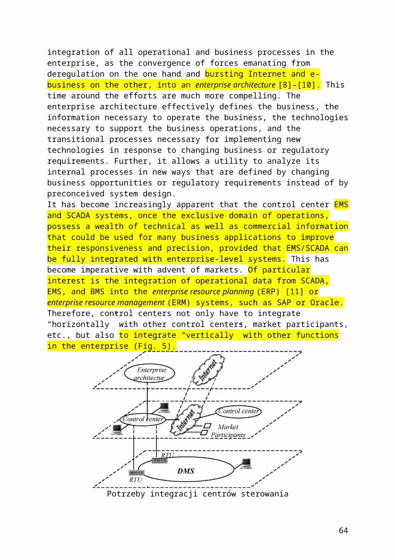
The Future of Electronic Power Processing and ConversionFrede Blaabjerg, Alfio Consoli, Jan A. Ferreira, and Jacobus D. van WykIEEE TRANSACTIONS ON INDUSTRY APPLICATIONS, VOL. 41, NO. 1, JANUARY/FEBRUARY 2005
{Przyszłe zastosowania technologii konwersji w elektroenergetyce}
III. DISCUSSION ON THE FUTURE OF ELECTRONIC POWER PROCESSING AND CONVERSION AT FEPPCON VA. Progressing From Power Electronics Into Systems1) Relevant Issues: Three levels exist in power electronics, namely, components, circuits, and systems. Components and more specifically semiconductor devices have been the major technology drivers. Circuits and topologies have received much attention and, consequently, the middle level has matured. Circuit topology innovations have stagnated, perhaps with the exception of high power. Research opportunities still exist with devices. Systems need to get more attention and this is where we see the main challenge for the future. Performance, control issues, and system integration issues have become more important than power electronic technology. Reliability and cost will be very important for consumer acceptance.During the past two decades not much has changed regarding the basic principles and the technology that is used to construct converters. Despite this the industry has managed to reduce the cost and increase the power density substantially. Component factories have become more cost effective and moved to countries where the labor is cheap and productive. The increase in power densities has been achieved by doing circuit optimization in an engineering environment where a significant amount of technology standardization has occurred in the face of enormous cost pressures. These cost pressures make it difficult to change power electronics technology as such and a better option is to invest in the way that power electronics is applied in systems.We need to gain a better understanding of the role that power electronics plays in systems. Power electronics is not in a position to dictate new developments. The market pull is the important driver. Power electronics is not a technology push. Power electronics is an enabling technology that means that we play a supporting role only. If we want to play a bigger role, then we need to understand the systems issues. We should aim to do power processing and not power electronics. The demand is for the system integration of power processing.The main issue that came forward from the discussions was that the power electronics community tends to think and work too narrowly. We seem to find it difficult to integrate our knowledge into systems. A similar situation exists with reliability. The problem is that we do not really know how to deal with it. If we can quantify and control it, power electronics will more readily be applied in power systems, for example.2) Future Developments and Challenges: An opportunity exists for power electronics to expand its role dealing with smart, intelligent, and efficient power processing in all kinds of applications. Power systems constitute
64
one application that offers many possibilities. Another application is mechatronic systems.Power systems applications in particular need to be revitalized at universities because old engineers are retiring and replacements are not being trained. If something is not urgently done then we will not be able to address the challenges in power systems. As a dynamic discipline that attracts students, the power electronics education program can contribute to this need in power engineering.In educating engineers a broader background is required, including mechanical issues such as heat transfer and fatigue, which are now often neglected. In order to expand our role we should grow integrated projects at universities. In the process we will have to take aspects on board that we, classical electrical engineers, may not be comfortable with. A good example of such an issue is thermal management. New technologies and better designs of the thermal housekeeping may have more potential for increasing the power density than the conventional electrical approach of improving the efficiency.This new role of power electronics is not something that can happen overnight. It has to be addressed at the grass roots level, in the education programs. The reductionism educational paradigm has to be turned around and at universities we have to go back from specialist to generalist degrees. The power electronics engineer of the future has to be multidisciplinary. For example, electrochemistry background in the educational program is important and a new/mixed curriculum is required. We have to get physicists involved. Integration has to occur at a faculty level. There is a general need for the integration of different fields in the educational program; the primary need is at the faculty level.B. Energy Storage1) Relevant Issues: The use of alternative energy sources on a large scale requires new technologies such as reliable power electronics interface, new system control issues, as well as energy storage systems. It could be combined with the possibility of the installation of other highly dynamic power sources, if they can be controlled in a way so the sum of alternative power and dynamic power is constant. Furthermore, HVDC in larger regions will be linked to balance out regional differences in power generation (wind) and the power consumption. However no real breakthrough is seen in large-scale energy storage systems. A high-capacity energy storage device was proposed based on oil and pneumatics for environmental friendliness, high efficiency and long lifetime. The first tests were already done and it could be a local solution.For energy storage capacities of a few kilowatthours, supercapacitors are proposed and used today as appropriate storage elements in applications like scooters and diesel electric propulsion. Supercapacitors have during the last few years seen an improved reliability and the cost has decreased. In tram applications the kinetic energy of the vehicle can be recuperated, which has major advantages such as the following:• fewer losses in overhead lines;• limited autonomy that allows crossings of trams without visual pollution in cities;
65
• lower current in overhead lines; fewer substations and less copper use can be considered; and supercapacitors are projected to be implemented in such applications.2) Future Developments and Challenges: Hydrogen economy will provide a good opportunity for power electronics in the long term but also to provide a higher number of storage facilities. However, the production, storage, and transportation of hydrogen are still the main limiting factors that have to be overcome in the near future if such a society is to be developed. In power systems, hydrogen storage is not seen to be an efficient alternative compared to pumped hydro as the latter has a much higher efficiency and is already a mature technology. However, the capacity for pumped hydro is limited by geographical constraints (hills, mountains) and in many areas this is not possible without transporting the energy over long distances. In an automotive application the situation is different. Ultracapacitors seem to be the ideal devices to recover the kinetic (braking) energy. Their energy and power densities have improved fivefold in the last five years. Other benefits are: fewer substations, operation in areas with no overhead lines, and reduced installed power. Ultracapacitors have become attractive from a cost perspective. In diesel-electric systems the diesel-engine size can be reduced and the diesel engine can be turned off in stations.Storage systems should be used to decouple subsystems in power systems during transients. Efficient energy storage is one of the main challenges in the next decade in order to optimize the use of energy in many applications.C. Power Systems1) Relevant Issues: The power system has gotten more attention in recent years due to different blackouts globally. Power electronics can improve the efficiency of generation, in transmission systems, and in distribution systems. Despite this, power electronic solutions have so far failed to penetrate the utility market meaningfully. Although US electricity market is growing at 2.5% per year the investment in transmission and distribution infrastructures has unfortunately declined.The electric grid has minimal active control, automation and communication capabilities as the main issue is cost reduction. Other networks (e.g. phones, Internet, etc.) are now smart and fault tolerant, and provide higher reliability and availability at low cost. Transmission systems are not yet designed for deregulation of the energy market. For example, the U.S. power grid infrastructure needs modernization as the future grid will have to be smart, fault tolerant, dynamically and statically controllable, and finally energy efficient.Power quality represents a significant opportunity to apply power electronics to power systems. However, it is still necessary to establish knowledge about how customers will be willing to pay for having power electronics in power systems. One good reason could be that industrial productivity reduction is related to power quality.2) Future Developments and Challenges: The future power systems have to deal with distributed subsystems, distributed energy storage systems, active control of each subsystem, and fast exchange of information among the subsystems. Power electronics penetration in the power system PQ market is conditioned by who will pay for it. Investigation of possible
66
solutions to power system problems should be carried on by means of small steps to be applied to small grids (ships, cars, airplanes) first.Monitoring of current power systems and using new power systems in developing countries as field for testing is necessary in order to learn before building new electrical systems, which is a major investment. It is expected that a large penetration of power electronics into power systems will happen within the next 25–30 years. One important application could be the utilization of power electronics to limit critical faults in transmission and distribution systems.
{Kolejny artykuł o przyszłości SEE}
Toward a smart gridMassoud Amin and Bruce WollenbergIEEE power & energy magazine september/october 2005
The North AMERICAN POWER GRID FACES MANY CHALLENGES THAT IT WAS NOT designed and engineered to handle. Congestion and atypical power flows threaten to overwhelm the system while demand increases for higher reliability and better security and protection. The potential ramifications of grid failures have never been greater as transport, communications, finance, and other critical infrastructures depend on secure, reliable electricity supplies for energy and control.Because modern infrastructure systems are so highly interconnected, a change in conditions at any one location can have immediate impacts over a wide area, and the effect of a local disturbance even can be magnified as it propagates through a network. Large-scale cascade failures can occur almost instantaneously and with consequences in remote regions or seemingly unrelated businesses. On the North American power grid, for example, transmission lines link all electricity generation and distribution on the continent. Wide-area outages in the late 1990s and summer 2003 underscore the grid’s vulnerability to cascading effects. Increased risks due to interdependencies among the critical infrastructures, combined with a purely business focus for service providers, have been recognized, as indicated by Dr. John Marburger, director of the White House Office of Science and Technology Policy, before the House Committee on Science on 24 June 2002.
The economy and national security of the United States are becoming increasingly dependent on U.S. and international infrastructures, which themselves are becoming increasingly interdependent.
Deregulation and the growth of competition in key infrastructures have eroded spare infrastructure capacity that served as a useful shock absorber.
Mergers among infrastructure providers have led to further pressures to reduce spare capacity as management has sought to wring out excess costs.
The issue of interdependent and cascading effects among infrastructures has received almost no attention.
Practical methods, tools, and technologies based on advances in the fields of computation, control, and communications are allowing power grids and other infrastructures to locally self-regulate, including automatic reconfiguration in the event of failures, threats, or disturbances. It is important to note that the key elements and principles of operation for interconnected power systems were established before the 1960s, before the emergence of extensive computer and communication networks. Computation is now heavily used in all levels of the power network: for planning and optimization, fast local control of equipment, and processing of field data. But coordination across the network happens on a slower timescale. Some coordination occurs under computer control, but much of it is still based on
67
telephone calls between system operators at the utility control centers, even—or especially—during emergencies.In this article, we present the security, agility, and robustness/survivability of a large-scale power delivery infrastructure that faces new threats and unanticipated conditions. By way of background, we present a brief overview of the past work on the challenges faced in online parameter estimation and real-time adaptive control of a damaged F-15 aircraft. This work, in part, provided the inspiration and laid the foundation in the 1990s for the flight testing of a fast parameter estimation/modeling and reconfigurable aircraft control system that allowed the F-15 to become self-healing in the face of damaged equipment.……….How to Make an Electric Power Transmission System SmartPower transmission systems also suffer from the fact that intelligence is only applied locally by protection systems and by central control through the supervisory control and data acquisition (SCADA) system. In some cases, the central control system is too slow, and the protection systems (by design) are limited to protection of specific components only.To add intelligence to an electric power transmission system, we need to have independent processors in each component and at each substation and power plant. These processors must have a robust operating system and be able to act as independent agents that can communicate and cooperate with others, forming a large distributed computing platform. Each agent must be connected to sensors associated with its own component or its own substation so that it can assess its own operating conditions and report them to its neighboring agents via the communications paths. Thus, for example, a processor associated with a circuit breaker would have the ability to communicate with sensors built into the breaker and communicate those sensor values using high-bandwidth fiber communications connected to other such processor agents.We shall use a circuit breaker as an example. We will assume that the circuit breaker has a processor built into it with connections to sensors within the circuit breaker (Figure 2). We also provide communication ports for the processor where the communication paths follow the electrical connection paths. This processor agent now forms the backbone of the smart grid as will be discussed later.
Rys. 2. wyłącznik z procesorem wewnętrznym i łąćzami komunikacyjnymiTable 1 compares the smart grid to protection systems and SCADA/energy management system (EMS) central systems. We propose a system that acts very fast (although not always as fast as the protections system), and like the protection system, its agents act independently while communicating with each other. As such, the smart grid is not responsible for removing faulted components, that is still the job of the protection system, but acts to protect the system in times of emergencies in a much faster and more intelligent manner than the central control system.
The Advantages of an Intelligent Processor in Each Component, Substation, and Power PlantWe presently have two kinds of intelligent systems used to protect and operate transmission systems: the protection systems and the SCADA/EMS/independent system operator (ISO)
68
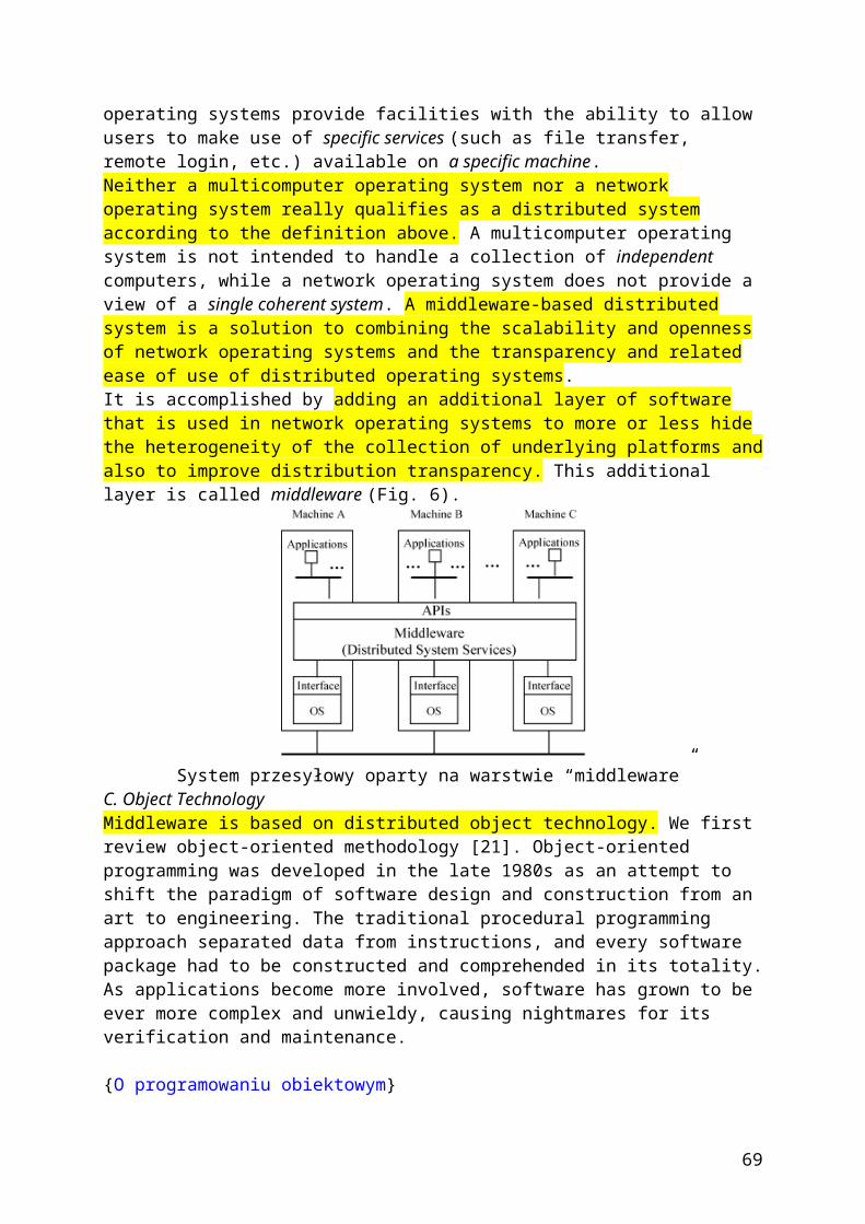
systems. We shall assume for the sake of this article that the protection systems are all digital. Of course, modern SCADA/EMS/ISO systems are all digital systems as well. Again for the sake of this article, we shall use the term central control instead of SCADA/EMS/ISO for reasons that will become apparent later.Modern computer and communications technologies now allow us to think beyond existing protection systems and the central control systems to a fully distributed system that places intelligent devices at each component, substation, and power plant. This distributed system will enable us to build a truly smart grid.The advantage of this becomes apparent when we see that each component’s processor agent has inputs from sensors in the component, thus allowing the agent to be aware of its own state and to communicate it to the other agents within the substation. On a system level, each agent in a substation or power plant knows its own state and can communicate with its neighboring agents in other parts of the power system. Having such independent agents, which know about their own component or substation states through sensor connections, allows the agents to take command of various functions that are not performed by either the protection systems or the central control systems.Making Power Systems Components Act as Plug-and-Play InterconnectsOne of the problems common to the management of central control facilities is the fact that any equipment changes to a substation or power plant must be described and entered manually into the central computer system’s database and electrical one-line diagrams. Often, this work is done some time after the equipment is installed, resulting in a permanent set of incorrect data and diagrams in use by the operators. What is needed is the ability to have this information entered automatically when the component is connected to the substation— much as a computer operating system automatically updates itself when a new disk drive or other device is connected.When a new device is added to a substation, the new device automatically reports data such as device parameters and device interconnects to the central control computers. Therefore, the central control computers get updated data as soon as the component is connected; they do not have to wait until the database is updated by central control personnel. Figure 3 shows a substation bus-bar pair connected by a set of disconnect switches and a circuit breaker (the component processors are shown in orange). Each processor has communication paths connecting it with processors of the substation component in the same pattern as the electrical connections in the substation.
Rys. 3. Połączenie procesorów z układem komunikacyjnym w stacji za pomocą łączy optycznych
When a new component is added to the substation it also has a built-in processor. When the new device is connected, the communication path (Figure 4) is connected to the processor of the device it connects to electrically. When the new component’s processor and
69

communication path are activated, it can report its parameters and interconnects to the central control system, which can use the information to update its own database.Diagnostic Monitoring of all Transmission EquipmentPlacing the processing of sensor data in a local agent avoids the problem of sending that data to the central computer via the limited-capacity SCADA communications. The means for processing the local sensor data can be designed by the component manufacturer, and the agent then only needs to send appropriate alarms to the central computers. If the component is under such stress that the local agent determines it is in danger of being damaged, it can initiate shutdown through appropriate interconnects to the protections systems associated with the component.The Electric Power System as a Complex Adaptive SystemWhen the EPRI/DoD CIN/SI was planned in 1997–1998, complex adaptive system (CAS) research was beginning to produce an understanding of the complex overall behavior of natural and human systems. The electric power grid, made up of many geographically dispersed components, is itself a CAS that can exhibit global change almost instantaneously as a result of local actions. EPRI utilized CAS to develop modeling, simulation, and analysis tools for adaptive and reconfigurable control of the electric power grid. The underlying concept for the self-healing, distributed control of an electric power system involves treating the individual components as independent intelligent agents, competing and cooperating to achieve global optimization in the context of the whole system’s environment.The design includes modeling, computation, sensing, and control. Modeling began with the bulk power market in which artificial agents represent the buyers and sellers of bulk power. Based on this and other projects using evolutionary algorithms, EPRI developed a multiple adaptive agent model of the grid and of the industrial organizations that own parts of it or are connected to it.As presently configured, the Simulator for Electric Power Industry Agents (SEPIA) was a comprehensive, high-fidelity, scenario-free modeling and optimization tool for use by EPRI members to conduct computational experiments in order to gain strategic insights into the electricity marketplace. However, as new sensors and activators become available, this simulation will be expanded to provide the mathematical models and computational methods for real-time, distributed, intelligent control capable of responding locally to disturbances before they affect the global performance of the network. Several pertinent questions arise.1) What is an agent? Agents have evolved in a variety of disciplines, artificial intelligence, robotics, information retrieval, and so on, making it hard to get consensus on what they are.2) What types of agents are there? There are probably as many ways to classify intelligent agents as there are researchers in the field. Some classify agents according to the services they perform. System agents run as parts of operating systems or networks. They do not interact with end users but instead help manage complex distributed computing environments, interpret network events, manage backup and storage devices, detect viruses, and so on.3) How do adaptive agents work? An adaptive agent has a range of reasoning capabilities. It is capable of innovation (developing patterns that are new to it) as opposed to learning from experience (sorting through a set of predetermined patterns to find an optimal response). Adaptive agents can be passive (responding to environmental changes without attempting to change the environment) or active (exerting some influence on its environment to improve its ability to adapt).Despite the many advances of CIN/SI, the theoretical foundation remains incomplete for full modeling, measurement, and management of the power system and other complex networks. Two pertinent issues for future investigations are
why and how to develop controllers for centralized versus decentralized control
70

issues involving adaptive operation and robustness to disturbances that include various types of failures.
A key unresolved issue for complex interactive systems is understanding what control strategy (centralized, decentralized, or hybrid distributed) provides optimum performance, robustness, and security and for what types of systems and under what circumstances.If distributed sensing and control is organized in coordination with the internal structure existing in a complex infrastructure and the physics specific to the components they control, these agents promise to provide effective local oversight and control without excessive communications, supervision, or initial programming. These agents exist in every local subsystem and perform preprogrammed self-healing actions that require an immediate response. Such simple agents already are embedded in many systems today, such as circuit breakers and fuses as well as diagnostic routines. We are using extensions of this work to develop modeling, simulation, and analysis tools that may eventually make the power grid self-healing; the grid components could actually reconfigure to respond to material failures, threats, or other destabilizers. The first step is to build a multiple adaptive agent model of the grid and of the industrial organizations that own parts of it or are connected to it.Grid ComputingGrid computing can be described as a world in which computational power is as readily available as electric power and other utilities. According to Irving et al. in “Plug into Grid Computing,” Grid computing could offer an inexpensive and efficient means for participants to compete (but also cooperate) in providing reliable, cheap, and sustainable electrical energy supply.In addition, potential applications for the future power systems include all aspects that involve computation and are connected, such as monitoring and control, market entry and participation, regulation, and planning. Grid computing holds the promise for addressing the design, control, and protection of electric power infrastructure as a CAS.Making the Power System a Self-Healing Network Using Distributed Computer AgentsA typical sequence seen in large power system blackouts follows these steps:1) a transmission problem, such as a sudden outage of major lines, occurs2) further outages of transmission lines due to overloads leave the system islanded3) frequency declines in an island with a large generation load imbalance4) generation is taken off line due to frequency error5) the island blacks out6) the blackout lasts a long time due to the time needed to get generation back online. A self-healing grid can arrest this sequence.In Figure 5 we show three power plants connected to load substations through a set of looped transmission lines. Each plant and each substation will have its own processor (designated by a small red box in the figure). Each plant and substation processor is now interconnected in the same manner as the transmission system itself.
71
Rys.5. Połączenie trzech jednostek wytwórczych do stacji odbiorowej za pomocą układu telekomunikacyjnego w postaci pętli o takim samym kształcie jak sama sieć
elektroenergetyczna.
Rys. 6. Tworzenie wyspy po wystąpieniu zakłócenia w systemie
In Figure 6 we impose an emergency on the system; it has lost two transmission connections and is broken into two electrical islands. The processors in each island measure their own frequency and determine that there are load/generation imbalances in each island that must be corrected to prevent being shut down. The processors would have to determine the following:
the frequency in each island what constitutes each island what loads and what power plants are connected to each island what is the load versus generation balance in each island what control actions can be made to restore the load/generation balance.
The substation and power plant processors form a distributed computer network that operates independently of the central control system and can analyze the power system state and take emergency control actions in a time frame that cannot be done by central computer systems.How to effectively sense and control a widely dispersed, globally interconnected system is a serious technological problem. It is even more complex and difficult to control this sort of system for optimal efficiency and maximum benefit to the consumers while still allowing all its business components to compete fairly and freely. A similar need exists for other infrastructures, where future advanced systems are predicated on the near-perfect functioning of today’s electricity, communications, transportation, and financial services.Next Steps
72
In the coming decades, electricity’s share of total energy is expected to continue growing, and more intelligent processes will be introduced into this network. For example, controllers based on power electronics combined with wide-area sensing and management systems have the potential to improve the situational awareness, precision, reliability, and robustness of power systems. It is envisioned that the electric power grid will move from an electromechanically controlled system to an electronically controlled network in the next two decades. However, the electric power infrastructure, faced with deregulation (and interdependencies with other critical infrastructures) and an increased demand for high-quality and reliable electricity, is becoming more and more stressed.Several specific pertinent “grand challenges” to our power systems, economics, and control community persist, including:
the lack of transmission capability (transmission load is projected to grow in the next ten years by 22–25%; the grid, however, is expected to grow less than 4%)
grid operation in a competitive market environment (open access created new and heavy, long-distance power transfers for which the grid was not designed)
the redefinition of power system planning and operation in the competitive era the determination of the optimum type, mix, and placement of sensing,
communication, and control hardware the coordination of centralized and decentralized control.
For Further ReadingM. Amin, V. Gerhart, and E.Y. Rodin, “System identification via artificial neural networks: Application to on-line aircraft parameter estimation,” in Proc. AIAA/SAE 1997 World Aviation Congress, Anaheim, CA, 1997, p. 22. M. Amin, “National infrastructures as complex interactive networks,” in Automation, Control, and Complexity: An Integrated Approach, T. Samad and J. Weyrauch, Eds. New York: Wiley, 2000, ch. 14. pp. 263–286. M. Amin, “Toward self-healing infrastructure systems,” IEEE Computer, vol. 33, no. 8, pp. 44–53. M. Amin, “Toward self-healing energy infrastructure systems,” IEEE Comput. Appl. Power, vol. 14, no. 1, pp. 20–28. C.W. Gellings, M. Samotyj, and B. Howe, “The future’s power delivery system,” IEEE Power Energy Mag., vol. 2, no. 5, pp. 40–48.
{Przyszłość integracji farm wiatrowych do konwencjonalnego SEE}
INTEGRATING RENEWABLE ENERGY SOURCES INTO EUROPEAN GRIDST. J. HammonsUniversity of Glasgow, UK
ABSTRACTThis paper examines the integration of new sources of renewable energy into the power systems in Europe challenges and possible solutions, application of wind power prediction tools for power system operation, new tasks that create new solutions for communication in distribution systems, wind power in Greece, integration of dispersed generation in Denmark, EdF and distributed energy resources in France, and new renewable sources in Italy, The paper also examines the European Commission Technology Platforn's vision paper on Electricity Networks of the Future that was published in January 2006. In this respect, drivers towards Smart Grids, Grids today, and key challenges for Smart Grids of the Future are critically assessed.Keywords: Distributed generation, renewable energy, energy management, wind power, CHP, dispersed generation, interconnected power systems, smart grids.
73
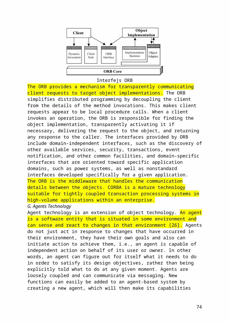
{Przyszłość integracji źródeł odnawialnych do konwencjonalnego SEE - wytyczne}
Power-Electronic Systems for the Grid Integration of Renewable Energy Sources: A SurveyJuan Manuel Carrasco, Member, IEEE, Leopoldo Garcia Franquelo, Fellow, IEEE,Jan T. Bialasiewicz, Senior Member, IEEE, Eduardo Galván, Member, IEEE,Ramón C. Portillo Guisado, Student Member, IEEE, Ma. Ángeles Martín Prats, Member, IEEE,José Ignacio León, Student Member, IEEE, and Narciso Moreno-Alfonso, Member, IEEEIEEE TRANSACTIONS ON INDUSTRIAL ELECTRONICS, VOL. 53, NO. 4, AUGUST 2006
Abstract—The use of distributed energy resources is increasingly being pursued as a supplement and an alternative to large conventional central power stations. The specification of a power electronic interface is subject to requirements related not only to the renewable energy source itself but also to its effects on the power-system operation, especially where the intermittent energy source constitutes a significant part of the total system capacity. In this paper, new trends in power electronics for the integration of wind and photovoltaic (PV) power generators are presented. A review of the appropriate storage-system technology used for the integration of intermittent renewable energy sources is also introduced. Discussions about common and future trends in renewable energy systems based on reliability and maturity of each technology are presented.………..C. Grid-Connection Standards for Wind Farms1) Voltage Fault Ride-Through Capability of Wind Turbines:As the wind capacity increases, network operators have to ensure that consumer power quality is not compromised. To enable a large-scale application of the wind energy without compromising the power-system stability, the turbines should stay connected and contribute to the grid in case of a disturbance such as a voltage dip. Wind farms should generate like conventional power plants, supplying active and reactive powers for frequency and voltage recovery, immediately after the fault occurred.Thus, several utilities have introduced special grid connection codes for wind-farm developers, covering reactive power control, frequency response, and fault ride through, especially in places where wind turbines provide for a significant part of the total power. Examples are Spain, Denmark, and part of Northern Germany.The correct interpretation of these codes is crucial for windfarm developers, manufacturers, and network operators. They define the operational boundary of a wind turbine connected to the network in terms of frequency range, voltage tolerance, power factor, and fault ride through. Among all these requirements, fault ride through is regarded as the main challenge to the wind-turbine manufacturers. Although the definition of fault ride through varies, the German Transmission and Distribution Utility (E.ON) regulation is likely to set the standard [8]. This stipulates that a wind turbine should remain stable and connected during
74
the fault while voltage at the point of connection drops to 15% of the nominal value (i.e., a drop of 85%) for a period of 150 ms (see Fig. 5).
allowed to disconnect from the grid. When the voltage is in the shaded area, the turbine should also supply a reactive power to the grid in order to support the grid-voltage restoration.2) Power-Quality Requirements for Grid-Connected Wind Turbines: The grid interaction and grid impact of wind turbines have been focused on during the past few years. The reason behind this interest is that wind turbines are among the utilities considered to be potential sources of bad power quality. Measurements show that the power-quality impact of wind turbines has been improved in recent years. Especially, variable-speed wind turbines have some advantages concerning flicker. But, a new problem arose with variable-speed wind turbines. Modern forced-commutated inverters used in variable-speed wind turbines produce not only harmonics but also interharmonics.The International Electrotechnical Commission (IEC) initiated the standardization on the power quality for wind turbines in 1995 as part of the wind-turbine standardization in TC88, and ultimately 1998 IEC issued a draft IEC-61400-21 standard for “power-quality requirements for Grid Connected Wind Turbines” [9]. The methodology of that IEC standard consists of three analyses. The first one is the flicker analysis. IEC-61400-21 specifies a method that uses current and voltage time series measured at the wind-turbine terminals to simulate the voltage fluctuations on a fictitious grid with no source of voltage fluctuations other than the wind-turbine switching operation. The second one regards switching operations. Voltage and current transients are measured during the switching operations of the wind turbine (startup at cut wind speed and startup at rated wind speed). The last one is the harmonic analysis, which is carried out by the fast Fourier transform (FFT) algorithm. Rectangular windows of eight cycles of fundamental frequency width, with no gap and no overlapping between successive windows, are applied. Furthermore, the current totalTHD is calculated up to 50th harmonic order. Recently, high-frequency (HF) harmonics and interharmonics are treated in the IEC 61000-4-7 and
75
IEC 61000-3-6 [10], [11]. The methods for summing harmonics and interharmonics in the IEC 61000-3-6 are applicable to wind turbines. In order to obtain a correct magnitude of the frequency components, the use of a well-defined window width, according to the IEC 61000-4-7, Amendment 1, is of a great importance, as has been reported in [12]. Wind turbines not only produce harmonics; they also produce interharmonics, i.e., harmonics that are not a multiple of 50 Hz. Since the switching frequency of the inverter is not constant but varies, the harmonics will also vary. Consequently, since the switching frequency is arbitrary, the harmonics are also arbitrary. Sometimes they are a multiple of 50 Hz, and sometimes they are not.D. Trends in Wind-Power Technology1) Transmission Technology for the Future—Connecting Wind Generation to the Grid: One of the main trends in windturbine technology is offshore installation. There are great wind resources at sea for installing wind turbines in many areas where the sea is relatively shallow. Offshore wind turbines may have slightly more favorable energy balance than onshore turbines, depending on the local wind conditions. In places where onshore wind turbines are typically placed on flat terrain, offshore wind turbines will generally yield some 50% more energy than a turbine placed on a nearby onshore site. The reason is that there is less friction on the sea surface. On the other hand, the construction and installation of a foundation requires 50% more energy than onshore turbines. It should be remembered, however, that offshore wind turbines have a longer life expectancy than onshore turbines, which is around 25–30 years. The reason is that the low turbulence at sea gives lower fatigue loads on the wind turbine. Conventional heating–ventilation–airconditioning (HVAC) transmission systems are a simple and cost-efficient solution for the grid connection of wind farms. Unfortunately, for offshore wind parks, the distributed capacitance of undersea cables is much higher than that of overhead power lines. This implies that the maximum feasible length and power-transmission capacity of HVAC cables is limited. Grid access technology in the form of high-voltage dc (HVDC) can connect the wind-farm parks to the grid and transmit the power securely and efficiently to the load centers. Looking at the overall system economics, HVDC transmission systems are most competitive at transmission distances over 100 km or power levels of between approximately 200 and 900 MW. The HVDC transmission offers many advantages over HVAC [13].1) Sending and receiving end frequencies are independent.2) Transmission distance using dc is not affected by cable charging current.3) Offshore installation is isolated from mainland disturbances and vice versa.4) Power flow is fully defined and controllable.5) Cable power losses are low.6) Power-transmission capability per cable is higher.
76
Fig.6
Classical HVDC transmission systems [as shown in Fig. 6(a)] are based on the current source converters with naturally commutated thyristors, which are the so-called line commutated converters (LCCs). This name originates from the fact that the applied thyristors need an ac voltage source in order to commutate and thus only can transfer power between two active ac networks. They are, therefore, less useful in connection with the wind farms as the offshore ac grid needs to be powered up prior to a possible startup. A further disadvantage of LCC-based HVDC transmission systems is the lack of the possibility to provide an independent control of the active and reactive powers. Furthermore, they produce large amounts of harmonics, which make the use of large filters inevitable. Voltage-source-converter (VSC)-based HVDC transmission systems are gaining more and more attention not only for the grid connection of large offshore wind farms. Nowadays, VSCbased solutions are marketed by ABB under the name “HVDC Light” [14] and by Siemens under the name “HVDC Plus.”Fig. 6(b) shows the schematic of a VSC-based HVDC transmission system. This comparatively new technology (with first commercial installation in 1999) has only become possible by the development of the IGBTs, which can switch off currents. This means that there is no need for an active commutation voltage. Therefore, VSC-based HVDC transmission does not require a strong offshore or onshore ac network and can even start up against a dead network (black-start capability). But, VSC-based systems have several other advantages. The active and reactive powers can be controlled independently, which may reduce the need for reactive-power compensation and can contribute to the stabilization of the ac network at their connection points [15].2) High-Power Medium-Voltage Converter Topologies: In order to decrease the cost per megawatt and to increase the efficiency of the wind-energy conversion, nominal power of wind turbines has been continuously growing in the last years [16].
77
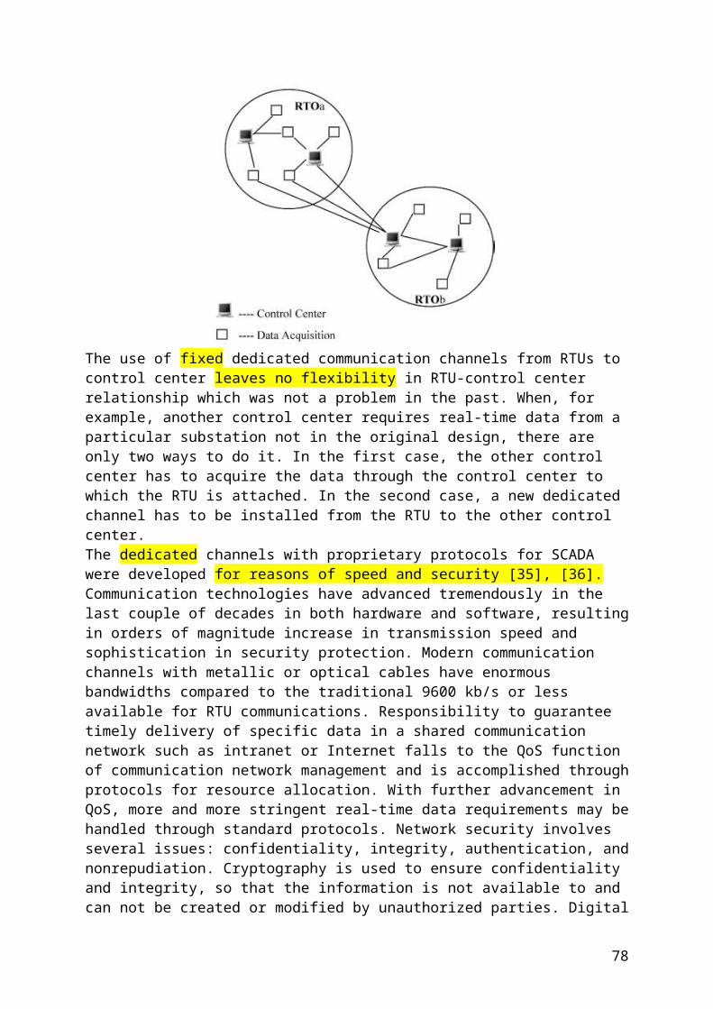
The different proposed multilevel-converter topologies can be classified into the following five categories [17]:1) multilevel configurations with diode clamps;2) multilevel configurations with bidirectional switch interconnection;3) multilevel configurations with flying capacitors;4) multilevel configurations with multiple three-phase inverters;5) multilevel configurations with cascaded single-phase H-bridge inverters.A common feature of the five different topologies of multilevel converters is that, in theory, all the topologies may be constructed to have an arbitrary number of levels, although in practice, some topologies are easier to realize than others.As the ratings of the components increase and the switching and conducting properties improve, the advantages of applying multilevel converters become more and more evident. In recent papers, the reduced content of harmonics in the input and output voltages is highlighted together with the reduced electromagnetic interference (EMI) [18]. Moreover, the multilevel converters have the lowest demands for the input filters or alternatively reduced number of commutations [19]. For the same harmonic performance as a two-level converter, the switching frequency of a multilevel converter can be reduced to 25% that results in the reduction of the switching losses [20]. Even though the conducting losses are higher in the multilevel converter, the overall efficiency depends on the ratio between the switching and the conducting losses.The most commonly reported disadvantage of the multilevel converters with split dc link is the voltage unbalance between the capacitors that integrate it. Numerous hardware and software solutions are reported: the first one needs additional components that increase the cost of the converter and reduce its reliability; the second one needs enough computational capacity to carry out the modulation signals. Recent papers illustrate that the balance problem can be formulated in terms of the model of the converter, and this formulation permits solving the balancing problem directly modifying the reference voltage with a relatively low computational burden [21], [22].
Trends on wind-turbine market are to increase the nominal power (some megawatts) and due to the voltage and current ratings. This makes the multilevel converter suitable for modern high-power wind-turbine applications. The increase of voltage rating allows for connection of the converter of the wind turbine directly to the wind-farm distribution network, avoiding the use of a bulky transformer [23] (see Fig. 7). The main drawback of some multilevel topologies is the necessity to obtain different dc-voltage independent sources needed for the multilevel modulation.
78
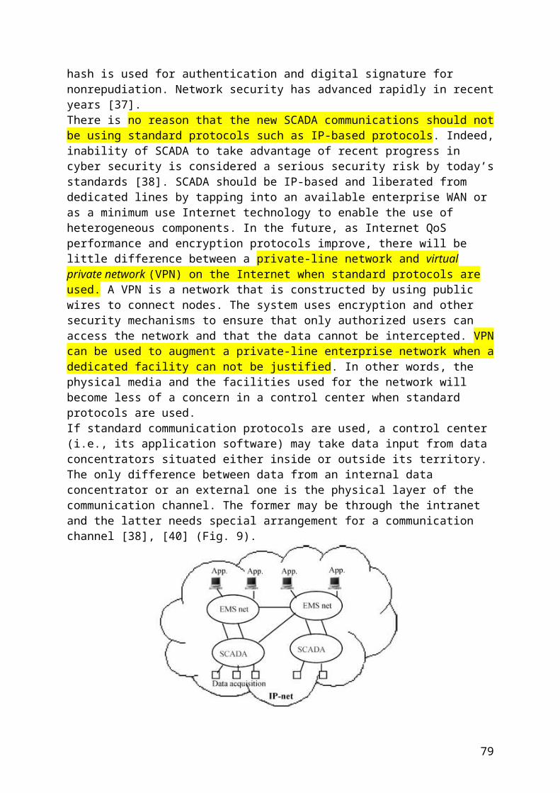
The use of low-speed permanent-magnet generators that have a large number of poles allows obtaining the dc sources from the multiple wounds of this electrical machine, as can be seen in Fig. 8. In this case, the power-electronic building block (PEBB) can be composed of a rectifier, a dc link, and an H-bridge. Another possibility is to replace the rectifier by an additional H-bridge. The continuous reduction of the cost per kilowatt of PEBBs is making the multilevel cascaded topologies to be the most commonly used by the industrial solutions.3) Direct-Drive Technology forWind Turbines: Direct-drive applications are on increase because the gearbox can be eliminated. As compared to a conventional gearbox-coupled windturbine generator, a direct-drive generator has reduced the overall size, has lower installation and maintenance cost, has a flexible control method and quick response to wind fluctuations, and load variation. For small wind turbine, permanent magnet synchronous machines are more popular because of their higher efficiency, high-power density, and robust rotor structure as compared to induction and synchronous machines.A number of alternative concepts have been proposed for direct drive electrical generators for use in grid-connected or standalone wind turbines. In [24], the problem to adapt a standard permanent-magnet synchronous machine to a direct-drive application is presented. A complete design of a low-speed direct drive permanent-magnet generator for wind application is depicted in [25] and [26]. A new trend that is very popular for propulsion systems applications is to use an axial flux machine [27]. These new machines are applied in small-scale wind and water-turbine direct-drive generators because higher torque density can be obtained in a more simple and easy way.4) Future Energy-Storage Technologies Applied in Wind Farms: Energy-storage systems can potentially improve the technical and economic attractiveness of wind power, particularly when it exceeds about 10% of the total system energy (about 20%–25% of the system capacity). The storage system in a wind farm will be used to have a bulk power storage from wind during the time-averaged 15-min periods of high availability and to absorb or to inject energy over shorter time periods in order to contribute to the grid-frequency stabilization. Several kinds of energy-storage technologies are being applied in wind farms. For wind-power application, the flow (zinc bromine) battery system offers the lowest cost per energy stored and delivered. The zinc–bromine battery is very different in concept and design from the more traditional batteries such as the lead–acid battery. The battery is based on the reaction between two commonly available chemicals: zinc and bromine. The zinc–bromine battery offers two to three times higher energy density (75–85 Wh per kilogram) along with the size and weight savings over the present lead/acid batteries. The power characteristics of the battery can be modified for selected applications. Moreover, zinc–bromine battery suffers no loss of performance after repeated cycling. It has a great potential for renewable energy applications [28].As the wind penetration increases, the hydrogen options become most economical. Also, sales of hydrogen as a vehicle fuel are more lucrative than reconverting the hydrogen back into electricity. Industry is
79
developing low-maintenance electrolysers to produce hydrogen fuel. Because these electrolysers require a constant minimum load, wind turbines must be integrated with grid or energy systems to provide power in the absence of wind [28].Electrical energy could be produced and delivered to the grid from hydrogen by a fuel cell or a hydrogen combustion generator. The fuel cell produces power through a chemical reaction, and energy is released from the hydrogen when it reacts with the oxygen in the air. Also, wind electrolysis promises to establish new synergies in energy networks. It will be possible to gradually supply domestic-natural-gas infrastructures, as reserves diminish, by feeding hydrogen from grid-remote wind farms into natural-gas pipelines. Fig. 9 shows a variable-speed wind turbine with a hydrogen storage system and a fuel-cell system to reconvert the hydrogen to the electrical grid. {dać ten rysunek tutaj}………
Future trends in PVD. Future TrendsThe increasing interest and steadily growing number of investors in solar energy stimulated research that resulted in the development of very efficient PV cells, leading to universal implementations in isolated locations [44]. Due to the improvement of roofing PV systems, residential neighborhoods are becoming a target of solar panels, and some current projects involve installation and setup of PV modules in high building structures [45].PV systems without transformers would be the most suitable option in order to minimize the cost of the total system. On the other hand, the cost of the grid-connected inverter is becoming more visible in the total system price. A cost reduction per inverter watt is, therefore, important to make PV-generated power more attractive. Therefore, it seems that centralized converters would be a good option for PV systems. However, problems associated with the centralized control appear, and it can be difficult to use this type of systems.An increasing interest is being focused on ac modules that implement MPPT for PV modules improving the total system efficiency. The future of this type of topologies is to develop “plug and play systems” that are easy to install for nonexpert users. This means that new ac modules may see the light in the future, and they would be the future trend in this type of technology. The inverters must guarantee that the PV module is operated at the maximum power point (MPP) owing to use MPPT control increasing the PV systems efficiency. The operation around the MPP without too much fluctuation will reduce the ripple at the terminals of the PV module.Therefore, the control topics such as improvements of MPPT control, THD improvements, and reduction of current or voltage ripples will be the focus of researchers in the years to come [46]. These topics have been deeply studied during the last years, but some improvements still can be done using new topologies such as multilevel converters. In particular, multilevel cascade converters seem to be a good solution to increase the voltage in the converter in order to eliminate the HF transformer. A possible drawback of this topology is control complexity and increased
80
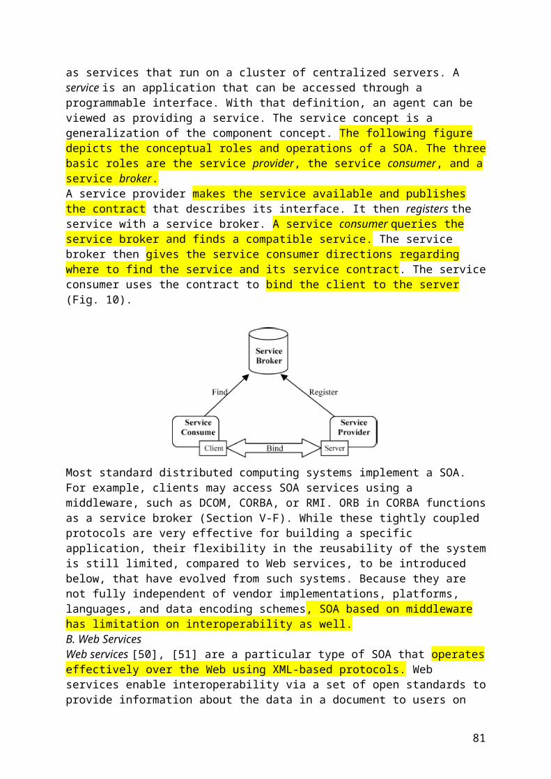
number of solid-state devices (transistors and diodes). It should be noticed that the increase of commutation and conduction losses has to be taken into account while selecting PWM or SVM algorithms.Finally, it is important to remember that standards, regarding the connection of PV systems to the grid, are actually becoming more and more strict. Therefore, the future PV technology will have to fulfil them, minimizing simultaneously the cost of the system as much as possible. In addition, the incorporation of new technologies, packaging techniques, control schemes, and an extensive testing regimen must be developed. Testing is not only the part of each phase of development but also the part of validation of the final product [44].………….
V. CONCLUSIONThe new power-electronic technology plays a very important role in the integration of renewable energy sources into the grid. It should be possible to develop the power-electronic interface for the highest projected turbine rating, to optimize the energy conversion and transmission and control reactive power, to minimize harmonic distortion, to achieve at a low cost a high efficiency over a wide power range, and to have a high reliability and tolerance to the failure of a subsystem component.In this paper, the common and future trends for renewable energy systems have been described. As a current energy source, wind energy is the most advanced technology due to its installed power and the recent improvements of the power electronics and control. In addition, the applicable regulations favor the increasing number of wind farms due to the attractive economical reliability. On the other hand, the trend of the PV energy leads to consider that it will be an interesting alternative in the near future when the current problems and disadvantages of this technology (high cost and low efficiency) are solved. Finally, for the energy-storage systems (flywheels, hydrogen, compressed air, supercapacitors, superconducting magnetic, and pumped hydroelectric), the future presents several fronts, and actually, they are in the same development level. These systems are nowadays being studied, and only research projects have been developed focusing on the achievement of mature technologies.
..............
The NETL Modern Grid Initiative:What Will the US Modern Grid Cost?Steven W. Pullins, Member, IEEE
The NETL Modern Grid InitiativeThe National Energy Technology Laboratory established the Modern Grid Initiative (MGI) in collaboration with Senator Robert C. Byrd, WV, to (1) help understand what the true issues with electric system performance are, and (2) determine what policy and technology actions are necessary to make the electric system an asset for business in the US.
81
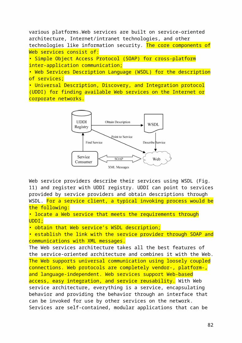
The Principal CharacteristicsIf the modern grid were designed and operated with these characteristics at the core, the nation’s grid would significantly improve in reliability, efficiency, and support to the consumers, especially those that rely on electricity for business and jobs.Self Heals – The grid monitors itself and automatically detects, analyzes, responds to, and restores grid components or network sections to maintain reliability, security, affordability, power quality, and an efficient state.
Motivates and Includes the Consumer – Individual, business, and industry consumers become integral, active parts of the electric power system. Participating in electricity markets will benefit both the individual consumer and overall system reliability.Resists Attack – It is critical for the modern grid to address security from the outset, making security a requirement and ensuring an integrated and balanced approach across the system.Provides Power Quality For 21st CenturyNeeds – Sensitive loads represent an increasing portion of the total power system load. The power quality delivered by the modern grid must be improved to meet the requirements of these sensitive loads. In addition, improvements in the design of the loads will make them more tolerant of distorted power.Accommodates all Generation and Storage Options – The modern grid will accommodate a portfolio of diverse generation types, necessitating a greatly simplified interconnection process analogous to plugand- play in today’s computer environment, particularly at the distributed energy resources level.Enables Markets – The modern grid will integrate electricity markets into the fabric of the electric system because operations, planning, pricing, and reliability are dependent on how open-access markets are designed and instituted. For this reason, it will not only support wholesale electric markets but also retail markets where applicable.Optimizes Assets and Operates Efficiently – Assets will be managed in concert so that, as a system, they can deliver functionality at a minimum cost. For example, advanced sensing and robust communications will allow early problem detection and corrective action.……..
Integration of Technologies is the KeyTruth is; there are no “silver bullets” for modernizing the grid. Looking for these has been one of the industry’s main weaknesses for a decade or more. The reality is that modernizing the grid requires many technologies (new and old), yet more integrated and more intelligent. Out of the Modern Grid team’s systems analysis, the common enablers of the seven principal characteristics are:Integrated Communications – High-speed, fully integrated, two-way communication technologies will make the modern grid a dynamic, interactive “mega-infrastructure” for real-time information and power
82
exchange. Open architecture will create a plug-and-play environment that securely networks grid components to talk, listen and interact.Sensing and Measurement – These technologies will enhance power system measurements and detect and respond to problems. They evaluate the health of equipment and the integrity of the grid and support advanced protective relaying; they eliminate meter estimations and prevent energy theft. They enable consumer choice and demand response, and help relieve congestion.Advanced Components – Advanced components play an active role in determining the grid’s behavior. The next generation of these power system devices will apply the latest research in materials, superconductivity, energy storage, power electronics, and microelectronics. This will produce higher power densities, greater reliability, and improved real-time diagnostics.Advanced Control Methods – New methods will be applied to monitor essential components, enabling rapid diagnosis and timely, appropriate response to any event. They will also support market pricing and enhance asset management.Improved Interfaces and Decision Support –In many situations, the time available for operators to make decisions has shortened to seconds. Thus, the modern grid will require wide, seamless, real-time use of applications and tools that enable grid operators and managers to make decisions quickly. Decision support with improved interfaces will amplify human decision making at all levels of the grid..........
Justifying Grid ImprovementsIt is often difficult to justify grid improvements to regulators. It starts with a good long-term vision, as we have discussed in the last few columns. Our experience says this skill set can be lacking in the utility industry.Next is the ability to quantify benefits or 'making the business case.' We need to get better at this task through the hard work of developing intelligent business cases and vetting them through rigorous review. Then we should shamelessly re-use those models again and again to make the case to management and regulators.
83
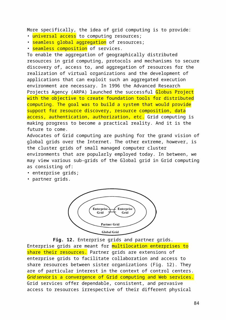
What Will It Cost?While traditionalists scoff at the benefits side of the equation, there is also good news on the cost side. The NETL Modern Grid team has researched the cost of modernizing the nation’s grid. From the team’s recent work, as well as the analysis from other projects, the cost of modernizing the grid is not large in comparison to the capital expenditures already planned. First, a new perspective must be considered. Modernizing the grid is not a pure addition to the capital cost of the utility industry. The actions the industry would take to modernize the grid would replace other capital actions already in the traditional expansion and reliability plans. The research shows that most plans add reliability through construction of central generation and transmission resulting in an ever increasing under-utilization of these assets. Why? Because, new central generation and transmission are not the most efficient ways to address peak demand. However, that is what the industry is used to doing.
A Framework for Operation and Control of Smart Grids with Distributed GenerationX. P. Zhang, Senior Member, IEEEIEEE, 2008
{Wg autorów FACTS, Distributed Generation oraz regulatory HVDC są najważniejszymi elementami Smart Grids}……….All FACTS devices and HVDC links are helpful in stability control of power systems. The shunt type FACTS device is more useful to control system voltage and reactive power while the series type FACTS device is more suitable for power flow control. The series-shunt type controller - UPFC can be used to control the active and reactive power flow of a transmission line and bus voltage independently. The series type FACTS controller – IPFC (Interline Power Flow Controller) can be used to control power flows of two transmission lines while
84
the active power between the two transmission lines can be exchanged. The newly developed VSC HVDC, which has similar control capability as that of the UPFC, can control both the independent active and reactive power flows of a transmission line and the voltage of a local bus [8]. However, the HVDC based conventional line commutated converter technique cannot provide voltage control and independent reactive power flow control. Another very important feature of VSC HVDC technique is that it can be very easily configured into a multi-terminal VSC HVDC. Research indicates VSC HVDC is a viable alternative to the UPFC for the purpose of network power flow and voltage control.
FACTS devices based on VSC techniques can be interconnected to implement various configurations and structures for different control purposes. While thyristor switched and/or controlled capacitors/reactors have limited performance and functionality, converter-based devices have superior performance, versatile functionality and various configuration possibilities. One shortcoming with converter based devices is, they are more expensive. With the continuous effort in R&D, it is likely that the costs of converter-based devices will be reduced further, and hence they will be more widely used in the next 5 years.There are two categories of FACTS devices available. Thyristor switched and/or controlled capacitors/reactors such as SVC (Static Var Compensator) and TCSC (Thyristor Controlled Series Compensator) were introduced in the late 1970s while Voltage-Sourced Converter-based FACTS devices such as STATCOM (Static Synchronous Compensator), SSSC (Static Synchronous Series Compensator) and UPFC (Unified Power Flow Controller) were introduced in the mid 1980s. In the past, there has been a large number of SVCs installed in electric utilities. There are tens of conventional line commutated BTB (Back-to- Back) HVDC, a number of STATCOM and TCSC, three UPFCs, one IPFC and a number of VSC HVDC with BTB configuration installed within electric power systems around the World. It is anticipated that more STATCOM and VSC HVDC will be installed in the future.All FACTS devices and HVDC links are helpful in stability control of power systems. The shunt type FACTS device is more useful to control system voltage and reactive power while the series type FACTS device is more suitable for power flow control. The series-shunt type controller - UPFC can be used to control the active and reactive power flow of a transmission line and bus voltage independently. The seriesseries type FACTS controller – IPFC (Interline Power Flow Controller) can be used to control power flows of two transmission lines while the active power between the two transmission lines can be exchanged. The newly developed VSC HVDC, which has similar control capability as that of the UPFC, can control both the independent active and reactive power flows of a transmission line and the voltage of a local bus [8]. However, the HVDC based conventional line commutated converter technique cannot provide voltage control and independent reactive power flow control. Another very important feature of VSC HVDC technique is that it can be very easily configured into a multi-terminal VSC HVDC. Research indicates VSC HVDC is a viable alternative to the UPFC for the purpose of network power flow and voltage control.FACTS devices based on VSC techniques can be interconnected to implement various configurations and structures for different control purposes. While thyristor switched and/or controlled capacitors/reactors have limited performance and functionality, converter-based devices have superior performance, versatile functionality and various configuration possibilities. One shortcoming with converter based devices is, they are more expensive. With the continuous effort in R&D, it is likely that the costs of converter-based devices will be reduced further, and hence they will be more widely used in the next 5 years.B. Advanced FACTS and HVDC based Control for Smart GridsIt has been recognized that some transmission systems are not yet designed for the deregulated energy market. Power system infrastructure needs modernization as future power
85
systems will have to be smart, fault tolerant, dynamically and statically controllable, and energy efficient. FACTS and HVDC will be helpful to provide fast dynamic voltage, power flow and stability control of the power grid while enhancing efficient utilization of transmission assets. At the same time network congestion will be efficiently managed and system blackouts will be mitigated or avoided. In order to deal with the uncertainty of demand and generation, relocatable FACTS controllers have been developed [9].C. Integration of Wind Area Stability Control and Protection with FACTS and HVDC Control against System BlackoutsThe wide area stability control and protection system is considered the “eyes” that overlook the entire system area, and can capture any system incidents very quickly; while FACTS and HVDC are the “hands” of the system, which have very fast dynamic response capability and should be able to take very quick actions as soon as commands are received from the system operator. As the current situation stands, the fast dynamic control capability of FACTS and HVDC has not been fully explored and realized. The integration of the Wide Area Stability Control and Protection with FACTS and HVDC control will fully employ control capabilities of both technologies to achieve fast stability control of system, and to prevent the system against blackouts. Hence, a high network security and a reliable performance can be achieved. In order to tackle large-scale stability disturbance, a coordinated control of the integrated power network is required using the advanced stability control methodologies and/or wide area monitoring and control by using FACTS and HVDC control technologies.IV. A FRAMEWORK FOR OPERATION AND CONTROL OF SMART GRIDS WITH DISTRIBUTED GENERATIONA. Voltage ControlFor efficient, secure and reliable operation of electric power systems, it has been recognized that the following operating objectives should be satisfied: (a) Bus voltage magnitudes should be within acceptable limits; (b) System transient stability and voltage stability can usually be enhanced by proper voltage control and reactive power management; (c) The reactive power flows should be minimized such that the active and reactive power losses can be reduced. In addition, the by-product of the minimized reactive power flows can actually reduce the voltage drop across transmission lines and transformers.
In electrical power systems, voltage control and VAR management requires various voltage control devices installed at different locations of the systems. In addition to the voltage control devices, suitable control algorithms and software tools are needed to determine control settings of and coordinate the control actions of the voltage control devices sited at different locations of the systems. Basically the voltage control devices include shunt reactors and shunt capacitors, tap-changing transformers, synchronous condensers, synchronous generators, SVS, Converter-based FACTS controllers such as STATCOM, SSSC, UPFC, IPFC, GUPFC and HVDC light. Basically, the Converter-based FACTS have excellent dynamic reactive power and voltage control capability.Optimal Power Flow (OPF) is security and economic control-based optimization, which selects actions to minimize an objective function subject to specific operating constraints. Most OPF programs can perform more than one specific function. One of the OPF applications in Energy Management Systems is to minimize active power transmission losses while control of reactive power from generator and compensating devices and control of tap-changing transformers are scheduled and coordinated. The voltage control and VAR management by OPF tends to reduce circulating VAR flows, thereby promoting flatter voltage profiles.B. Stability Control
86
To maximize the benefits of FACTS technologies, much effort has been put to investigate the control capability of such devices to improve system stability. It has been proved that FACTS devices can provide positive add-on damping for small signal disturbance if proper damping controllers have been designed. The ideas of design approaches of conventional Power System Stabilizer (PSS) have been applied to the design of FACTS damping controllers.However, as FACTS devices are usually installed in transmission lines, this makes the damping controller design more challenging. For example, there may be difficulties in selecting feedback signals, in finding damping torque paths and so on. In recent years, Linear Matrix Inequality (LMI) technique has attracted much attention in the design of FACTS based damping controllers. The LMI technique has also been proposed for the design of robust damping control of FACTS, for example, H∞ mixed-sensitivity [10, 11], and mixed H2/H∞ with pole placement [12]. LMI based computational algorithms, which are different from the traditional analysis tools, have been widely investigated in system and control areas [13]. In [14], a new two-step LMI approach has been applied for design of output feedback damping controller for a multi-model system considering multiple operating points. This approach has been applied to design of STATCOM damping controller with consideration of STATCOM internal controllers. {To są te techniki omawiane w poprzednim grancie} C. A Framework for Operation and Control of Smart Grids with Distributed GenerationBasically voltage control can be done at a relative slow time scale while stability control should be considered at a fast time scale. In current practice, voltage control by conventional power plants can be coordinated via SCADA/EMS systems. With the introduction of DG into electricity networks, the following voltage control framework may be considered:1) Control Scheme 1: Coordinated voltage control by conventional power plants and reactive control resources such as transformers, mechanically switched capacitors/reactors, FACTS while DG maintains the power factor at the Grid Entry point. For this control scheme, DG is very much like a load, and responds to the grid passively. This reflects the current practice.2) Control Scheme 2: Coordinated voltage control by conventional power plants and reactive control resources such as transformers, mechanically switched capacitors/reactors, FACTS while DG maintains the voltage at the Grid Entry point. For this control scheme, DG is more actively participating in voltage control which such a control is still not coordinated. The may be done in the future as long as Grid Code is allowed.3) Control Scheme 3: Coordinated voltage control by conventional power plants and reactive control resources such as transformers, mechanically switched capacitors/reactors, FACTS and DG. For this control scheme, DG is fully participating in voltage control in a coordinated ways while DG or a group of DG can be operated very much like a conventional power plants with active control or management. This feature will be very important to work towards smart grids.Stability control and voltage control can be done at different scales. For DG, these controls can be actually decoupled with the decoupled converter controllers. With the introduction of DG into electricity networks, the following stability control framework may be considered:1) Control Scheme 1: Decentralized stability control by conventional power plants, FACTS and DG [15]. This reflects the current practice working towards smart grids.2) Control Scheme 2: Decentralized stability control by conventional power plants, FACTS and DG while some global control feedback signals. This reflects the future trend working towards smart grids.3) Control Scheme 3: Decentralized stability control by conventional power plants, FACTS and DG while coordinated control can be done through wide area measurement based technologies [14]. This reflects the future technologies for smart grids.Numerical examples will be presented to show the control frame for voltage and stability control.
87
V. CONCLUSIONSThis paper has discussed the framework for operation and control of smart grids with distributed generation, in which two controls such as steady state voltage control and stability control are included. In light of the different time scale requirements of steady state voltage control and stability control, a global coordinated strategy is proposed for voltage control while a decentralized control strategy is utilized for stability control. Within these two controls, the ways of the participation of distributed generation in system control, for instance, wind generation and FACTS in voltage control and stability control have been discussed in order to make the power grids smart in terms of operation flexibility and enhanced control capability.
VI. REFERENCES
[1] N. G. Hingorani, and L. Gyugyi, Understanding FACTS: Concepts and Technology of Flexible AC Transmission Systems, IEEE Press, 2000. [2] V. K. Sood, HVDC and FACTS Controllers: Applications of Static Converters in Power Systems, Kluwer Academic Publishers, 2004. [3] X.-P. Zhang, C. Rehtanz, and B. Pal, Flexible AC Transmission Systems: Modelling and Control, Springer, 2006. [4] A. P. Malozemoff, D. T. Verebelyi, S. Fleshler, D. Aized, and D. Yu, “HTS wire: status and prospects”, Proceedings of ICMC 2002, Xi'an China, 16 – 20 June 2002, pp. 424-430. [5] V. Karasik, K. Dixon, C. Weber, B. Batchelder, G. Campbell, and P. Ribeiro, “SMES for power utility applications: a review of technical and cost considerations”, IEEE Trans. on Applied Superconductivity, Vol. 9, No. 2, June 1999, pp. 541-546. [6] J-L Rasolonjanahary, E Chong, J Sturgess, A Baker, C Sasse, “A novel concept of fault current limiter”, 8th IEE International Conference on AC and DC Power Transmission, Savoy Place, London, 28 – 30 March 2006. [7] C. Rehtanz, “Wide area protection and online stability assessment based on phasor measurement units”, Proc. IREP 2001 - Bulk Power Systems Dynamics and Control V, Onomichi, Japan, 26 – 31 August 2001. [8] X.-P. Zhang, “Multiterminal voltage-sourced converter based HVDC models for power flow analysis”, IEEE Transactions on Power Systems, vol. 18, no. 4, 2004, pp.1877-1884. [9] D J Hanson, C Horwill, B D Gemmell, D R Monkhouse, "A STATCOMbased relocatable SVC project in the UK for National Grid", in Proc. 2002 IEEE PES Winter Power Meeting, New York City, 27 – 31 January 2002. [10] B. C. Pal, A.H. Coonick, A.H., I.M. Jaimoukha, and H. El-Zobaidi, “A Linear Matrix Inequality approach to robust damping control design in power systems with superconducting magnetic energy storage device”, IEEE Transactions on Power Systems, vol.15, no.1, 2000, pp. 356–362 [11] B. C. Pal., “Robust damping of interarea oscillations with unified powerflow controller”, IEE Proc. - Gener. Transm. Distrib., vol.149, no.6, 2002, pp.733-738 [12] M.M. Farsangi, Y.H. Song, and M. Tan, “Multi-objective design of damping controllers of FACTS devices via mixed H2/H∞with regional pole placement”, Int. J. Electr. Power Energy Syst, vol. 25, no. 5, 2003 pp. 339-346 [13] S. Boyd, L.E. Ghaoui, E. Feron, and V. Balakrishnan, Linear Matrix Inequalities in System and Control Theory, SIAM, Philadelphia, 1994 [14] C-F Xue, X-P Zhang, K R Godfrey, “Design of STATCOM Damping Control with Multiple Operating Points: A Multi-model LMI Approach”, IEE Proc. - Generation, Transmission and Distribution, vol. 153, no. 4, July 2006, pp. 375-382 [15] F. Wu, X.-P. Zhang, P. Ju, amd M.J.H. Sterling, “Decentralized Nonlinear Control of Wind Turbine with Doubly Fed Induction Generator”, IEEE Transactions on Power Systems, Accepted
A Vision of Electricity Network Congestion Management with FACTS and HVDCXiao-Ping Zhang, and Liangzhong YaoDRPT2008 6-9 April 2008 Nanjing China
88
{Zastosowanie urządzeń FACTS w zarządzaniu ograniczeniami przepływów mocy w przyszłości}
Abstract--This paper at first reviews the needs of the advanced FACTS and HVDC applications for future power systems in Europe, then discusses general principles of congestion management, which depend on market models, market policy and electricity network conditions. In connection with this, congestion management approaches that have been applied in different electricity markets are reviewed and compared. Based on these discussions, the impact of renewable energy particularly wind generation on electricity network congestion management and the imposed challenges on congestion management are presented. It has been recognized that applications of the Flexible AC Transmission System (FACTS) and HVDC technologies together with the Wide Area Measurement System (WAMS) may be cost effective and innovative control solutions to effectively manage the network congestion while ensuring the electricity network flexible enough to meet new and less predictable supply and demand conditions in competitive electricity markets.
Challenges in Integrating Distributed Energy Storage Systems into Future Smart GridAlaa Mohd1, Egon Ortjohann1, Andreas Schmelter1, Nedzad Hamsic1, Danny Morton2
1South Westphalia University of Applied Sciences/Division Soest, Lübecker Ring 2, 59494 Soest, Germany2The University of Bolton, Deane Road, Bolton, U.K.E-mail: [email protected], [email protected], [email protected]
{Optymalna integracja zdecentralizowanych źródeł energii w sieciach przyszłości}
978-1-4244-1666-0/08/$25.00 '2008 IEEE
Abstract- Distributed energy storage systems in combination with advanced power electronics have a great technical role to play and will have a huge impact on future electrical supply systems and lead to many financial benefits. So far, when Energy storage systems (ESSs) are integrated into conventional electric grids, special designed topologies and/or control for almost each particular case is required. This means costly design and debugging time of each individual component/control system every time the utility decides to add an energy storage system. However, our present and future power network situation requires extra flexibility in the integration more than ever. Mainly for small and medium storage systems in both (customers and suppliers) side as the storage moves from central generation to distributed one (including intelligent control and advanced power electronics conversion systems). Nevertheless, storage devices, standardized architectures and techniques for distributed intelligence and smart power systems as well as planning tools and models to aid the integration of energy storage systems are still lagging behind
Computer Network Security Management and Authentication of Smart Grids OperationsAlexander Hamlyn, Helen Cheung, Todd Mander, Lin Wang, Cungang Yang, Richard Cheung©2008 IEEE.
89
Abstract — Operations of electricity power systems have recently become more intricate due to development of microgrids, execution of open access competition, and use of networkcontrolled devices, etc. Computer networks therefore turn into an integral component of modern power-grid operations. This paper proposes a new utility computer network security management and authentication for actions / commands requests in smart-grid operations. This management covers multiple security domains in a new security architecture designed for smart power grids. This paper presents the strategy and procedure of security checks and authentications of commands requests for operations in the host area electric power system (AEPS) and interconnected multiple neighboring AEPS. Case studies of the new security management and authentication for smart grids operations are presented.
Functions of a Local Controller to Coordinate Distributed Resources in a Smart GridAngela Chuang, Member IEEE; Mark McGranaghan, Senior Member IEEE
{Lokalny regulator dla SmartGrid – poszczególne funkcje}
Abstract — This paper describes requirements for an intelligent local controller for smart grids. The controller manages the operation of a portion of the power system to achieve customer-configured preferences for reliability and power quality through the combined use of local generation and storage sources, responsive load, power conditioning, and standby electric service from the supply system. The controller coordinates the set points for local distributed generation and storage devices and provides an interface to the supply system for electricity market participation. Through ongoing optimization and information exchange, the controller coordinates local response to actual system and market conditions. Enabling automation of end-use customer preferences for electric service, the local controller represents a key technology component for smart grids.
I. BACKGROUNDThe smart grid of the future will incorporate widespread distributed resources that will include local generation sources, storage, and responsive loads. The communication infrastructure will allow coordination of these local resources with overall grid and market management, creating the need for local controllers that can optimize local decisions while taking into account the needs of the overall grid.This contribution describes requirements for an intelligent local controller for smart grids. While various capabilities identified are under research and development today [2]-[7], many other capabilities described in this paper do not yet exist.The controller manages the operation of a local portion of the power system (e.g. microgrid) to achieve customer configured preferences for reliability and power quality through the combined use of local generation
90
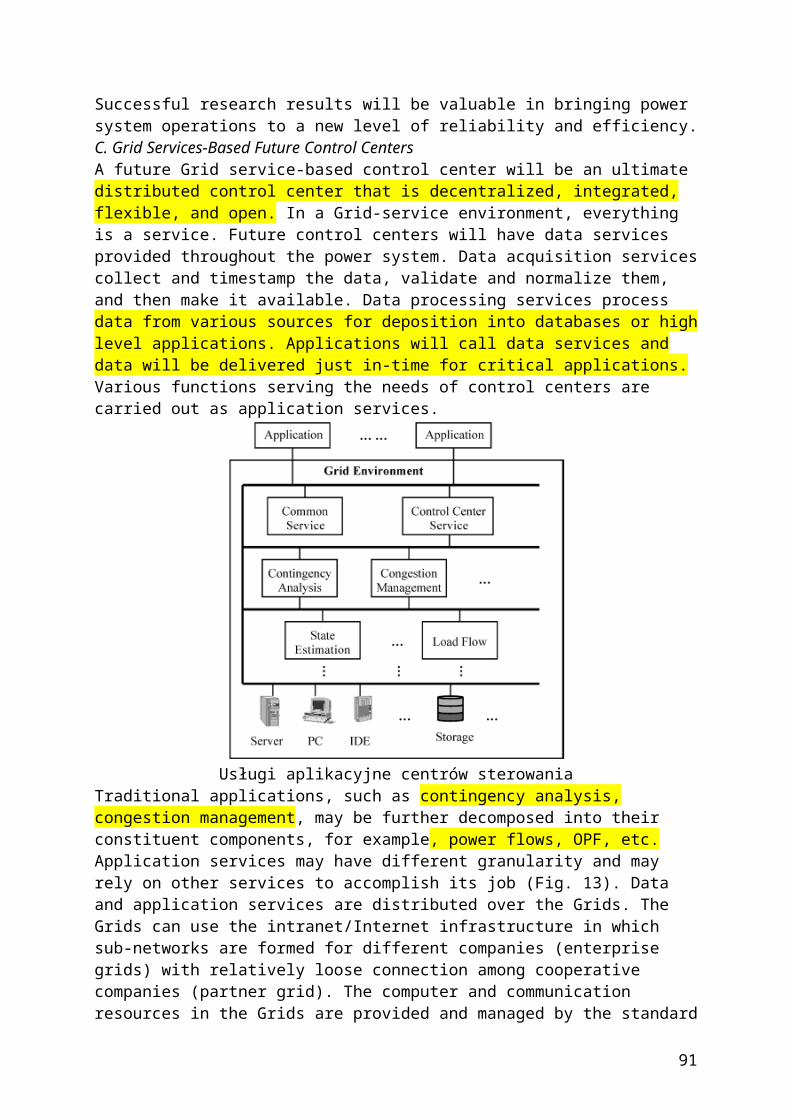
and storage sources, responsive load, power conditioning, and standby electric service from the supply system. The controller coordinates the set points for local distributed generation and storage devices and provides an interface to the supply system for electricity market participation and coordination of response to actual system and market conditions. The local controller considers economic, environmental, comfort and other end-use objectives as well as physical and regulatory constraints to enhance the efficient and effective use of electricity in day-to-day consumption.II. CHARACTERISTICS OF A LOCAL CONTROLLERThe local controller can be described from the end-use customer point of view. This perspective respects varying customer needs for electric service, such as variable levels of service quality and reliability. Accommodation of these dimensions of customer choice involves consideration of commercial information pertinent to local grid operations.The controller must operate cognizant of relevant commercial parameters including utility tariffs, energy market conditions, and prices from alternative sources of supply. Such commercial information typically originates outside of the local grid. The ability to connect to and leverage such information is a key requirement for intelligent coordination of distributed resources in a smart grid, particularly in competitive market environments. Information is received by the local controller through Internet-based information feeds or manual user entry of more static data. Both end-user preferences and end-use characteristics are inputs to the controller. Figure 2 illustrates information exchanged between the controller and other components of the smart grid. The types of information exchanged at the interface between the local grid and the supply system are also depicted.Prior work [1] outlines technology components and functions leveraged by the local controller to enable the described concept of smart grid operations to be realized. Components include “slave controllers” that manage local distributed resources, such as:
Distributed generation Storage Responsive load Smart switch controls
Together these components, under coordinated operation by the local controller, assure continuous supply to critical loads while achieving economic operation of local sources (e.g., generation, storage, and responsive loads).III. INFORMATION EXCHANGE MODELSThe local controller communicates with other key elements within a smart grid through a number of interfaces. Information is exchanged with the supply system, and local sources of generation, storage, and responsive load. Each interface between the local controller and other elements of the smart grid are shown in Figure 1.
91

Interfaces to load controllers manage local electricity usage in response to market conditions, local generation and storage conditions, and load priorities. If a problem in the supply system is detected, the local grid (or microgrid) can isolate itself through an interface to a fast switch (i.e., solid state breaker). Re-connection to the supply system may be based on analysis of supply system, local generation, and load conditions.Development of information exchange models for each of these key interfaces would facilitate interoperability between the local controller and many different devices that could be interfaced with it. Information models are needed for the following interfaces with the local controller.Supply system and market interfaceThis interface represents the electrical grid that supplies the local grid as well as the commercial markets for electricity that the local system may Local generator and storage device interfacesInterfaces with active sources of local generation enable coordinated operation of local generation and storage. Optimal utilization of these sources involves decision-making in combination with local electricity usage and external supply conditions, including market conditions.Load control interfacesExamples of load control interfaces include building energy management systems and load control devices retrofitted to end-use equipment. Load control interfaces enable communication with and/or control of loads in response to electricity prices, supply conditions, local generation conditions, or local usage priorities.Fast switch (solid state breaker)A fast switch or solid state breaker can isolate the local grid from the supply system virtually instantaneously in response to faults on the supply
92

system. The local controller manages reconnection to the supply system based on assessment of supply, local generation, and electricity usage conditions. IV. SCENARIOS OF APPLICATIONScenarios are considered for the application of the local controller. The scenarios provide the basis for identification of functional requirements that the local controller must support. The scenarios for application of the local controller listed below indicate a rich set of functional requirements to be supported. The reader is referred to Appendix A of [1] for elaboration on each of the following scenarios the local controller has been specified to support.
Response to emergency supply system conditions Response to dynamically changing prices Selling services to the supply system Considering environmental values in operations Forecasting local load and generation profiles Determining and executing day-ahead operations plan Responding to supply system disturbances Enabling operator changes to the default settings Response to contingencies within local grid (e.g., loss of local
generator. Grid-connected operation Isolated operation Missing data or loss of communications Black start Black start with grid-connected operation Black start with islanded operation
V. FUNCTIONAL REQUIREMENTSThis section provides a high-level introduction to functional requirements of the local controller. Functional requirements range from information processing and system configuration to decision-making and information presentation. These functions collectively support coordination of local operations by the controller under the scenarios identified in Section IV.Generally, each function can be specified by a basic description, identification of information inputs, description of outputs, and default actions.A. Classes of FunctionsFunctions of a local controller may be grouped into two main classes:
local grid reconfiguration functions functions related to economic, environmental, and customer comfort
considerationsThe local controller automates and optimizes distributed resources by controlling operating points of resources (i.e., local generators, storage units, and responsive loads). The operating points determined by the controller facilitate delivery of reliable and quality power to critical loads and processes, while considering actual and potential contingency conditions. Fast response to disturbances is achieved through utilization of slave controllers that ensure speed of response. This class of functions is designed to manage service reliability and quality in multiple configurations in response to supply system and local grid conditions.
93

The second class of functions of the controller supports economic, environmental and end-use comfort objectives, by adjusting local settings accordingly. The controller could balance decisions according to user preferences for “green power”, latest fuel prices, and other economic factors affecting end-use. Both classes of functions are required to achieve a broad range of end-use utilization objectives.B. Operating ModesThe local controller operates in one of three primary modes of operation, depending on conditions external to the local grid. These are:
normal mode emergency mode island mode
The operating mode is determined by conditions external to the local grid. Under normal operation, the local controller continuously determines appropriate set points for individual distributed resources. Like in normal mode, the controller determines appropriate set points under emergency mode. However, emergency conditions on the supply system cause the controller to restrict operations with additional constraints in emergency mode. For example the additional constraints may stem from commercial agreement to reduce load during system emergencies or to factor in critical peak pricing economics.From normal or emergency operation state, the local grid may transition into island mode due to a disturbance or other critical condition on the supply system.C. Optimization FunctionsA collection of functions support optimization under normal mode. Optimal operating plans are determined based on economic, environmental, and customer comfort objectives, respecting constraints under normal operations. These functions include economic operations schedule optimizer, economic load forecaster and calculator, economic generation forecaster and calculator, renewable generation forecaster and calculator, and economic storage forecaster and calculator. Functions under normal mode also include risk manager, local grid performance assessor, and ancillary service calculator. Basic descriptions of these functions along with their inputs and outputs and default actions are given in [1].A separate set of optimization functions apply under emergency mode. The local controller is optimizing set points with the local grid connected to the supply system, as in normal operation. However, functions are tailored for emergency operations, such as emergency economic schedule optimizer and emergency local grid performance assessor which pertain under emergency operations. In island mode, the local controller optimizes set points of local distributed resources based on reliability considerations and expectations on future supply conditions, such as expected system restoration time. Optimization functions in island mode include continuous island mode optimizer and island mode risk manager.D. System ConfigurationDistinct functions facilitate system configuration of information flows to be processed by the local controller. These functions enable configuration of the controller to obtain the information required for operational decision making. Information sources providing latest supply system conditions are
94

configured. A user may also configure online information sources that provide data for forecasting prices or indicate market opportunities to the local controller.With appropriate level of permission, an operator of the local grid system may configure physical characteristics of resources within the local grid. The operator configures alarm settings, ranks load priority orders among end uses, enters economic profiles, and configures local generation cost information. The local grid operator will have the broadest permission to configure the system and to view reports.E. Information ProcessingInformation processing functions support controller decision-making by processing informational inputs to derive designated outputs that the optimization functions rely on. The inputs are collected via the interface with the commercial market and supply system and/or the local grid resources and user interface. The inputs may include information on environmental conditions and restrictions that could influence the optimization functions described previously.Due to space considerations, a limited set of information processing functions are elaborated on in this subsection. The functions included support local controller operation under the following scenarios: emergency demand response, dynamic price response, and demand bidding to sell services to the supply system. These functions enable a broad range of services to be supplied by distributed energy resources within the context of smart grids. Valuable services that could be provided include ancillary services sold to electricity markets, voltage regulation for supporting the supply system, and demand response based on economic and emergency system conditions. The reader is referred to [1] for descriptions of other functions required to support application of the local controller under the remaining scenarios.1) Electricity Price ForecasterBased on user-selected forecasting methods and information sources, price forecaster processes latest information feeds (e.g, weather, transmission congestion, market prices) to produce daily electricity price forecasts. Resulting forecasted prices are available to the user through the UI as well as locally to support optimization functions. If any required input data is missing across M consecutive time intervals (where M is user specified), then this function returns the average of the last N consecutive input values (where N is user specified).2) Dynamic Price ProcessorThe dynamic pricing processor simply takes retail price signals as input and provides these signals to the appropriate local controller functions as well as local grid components (e.g., responsive load). Local controller functions that rely on dynamic pricing information include the electricity cost calculator, electricity price forecaster, and economic optimization function. In the event any retail prices are missing from the input stream, the price processor computes an average value and indicates the “repaired” nature of the resulting prices outputted.3) Electricity Cost CalculatorConsidering actual metered usage and retail electricity prices, the electricity cost calculator outputs estimates of electricity cost for the time
95

intervals of user interest (e.g., day, hour). This function determines retail prices based on the applicable retail tariff structure, which may be some form of dynamic pricing. In the event of bad or missing input data, this function substitutes fault data with an estimated “repaired” value, which is flagged as a repaired value.4) Electricity Cost ForecasterUnlike the electricity cost calculator which utilizes actual metered usage, the electricity cost forecaster provides a projection of electricity costs based on forecasted or scheduled usage. This function determines forecasted costs based on the applicable retail tariff structure, which may be some form of dynamic pricing. Forecasted costs are outputted for time intervals of user interest, and “repaired” forecasted values remedy missing or bad input data.5) Demand Bid Opportunity AssessorThis function identifies eligible demand-side market opportunities (i.e., quantities, prices, and time window for each market opportunity) based on continuous scan of the latest system and market conditions. The function lists eligible bid alternatives among configured market opportunities. In the event of insufficient information for the function to recognize the opportunity from the supply system, the opportunity assessor logs an error message and alerts the local grid operator of the potential opportunity.6) Demand Bid SubmitterThis function packages and submits formal bids to the supply system (i.e., bid prices, quantities, and schedules for targeted market opportunities), along with the identification and type of resource(s) supporting the bids. Inputs taken include a schedule of available services to be sold to the supply system and the identification of the resources. This function respects bidding timeframes per user configuration in packaging and presenting bids to the supply system. If a bid is rejected or the supply system fails to acknowledge the bid, then this function resubmits the bid as long as the opportunity is still open. If the function fails to receive acknowledgement after R resubmission attempts (where R is user configured), then the function notifies the local grid operator by default.7) Bid Award AcknowledgerUpon receipt of any bid award notification from the supply system, this function acknowledges and processes the notification by sending an acknowledgement signal to the supply system. If an erroneous bid award notification is received that is not recognized by the local system, instead of issuing acknowledgement this function notifies the local grid operator of the exception for manual determination of a course of action.8) Local Grid Resource Availability UpdaterBased on resource status information from slave controllers and known characteristics of local distributed resources (via configuration), the availability update function keeps the supply system apprised of latest availability of local grid resources. This function continuously assesses and aggregates latest resource status information to present an aggregated view to the external supply system. The aggregated information may be polled by the supply system or provided automatically at set time intervals, per system configuration. If latest resource status information is not received, then this function substitutes missing data with the last
96

value received. However, after X time intervals of missing status information (where X is user configured), the function outputs zero resource availability and notifies the operator of the default condition.9) Local Grid Resource Deployment SchedulerThis function determines resource deployment schedules (i.e., dispatch schedules) for individual local distributed resources. The schedules are optimized under “normal mode” according to end-use priorities, market opportunities, and optimization functions that apply under normal operations. The optimized resource deployment schedules are provided to the supply system and slave controllers to guide set points. If a feasible resource deployment schedule can not be determined, however, then the scheduler function issues an exception notifying the local grid operator. It also reverts to a default resource deployment schedule based on user settings and historic operating data.10) Local Grid Resource DispatcherThis function dispatches local distributed resources by issuing dispatch schedules or control signals to individual resources. The function also issues notification messages to users to prompt manual actions (e.g., manually actuated demand response). Inputs to the function include dispatch signals received from the supply system and the optimal resource dispatch schedules outputted by the resource deployment scheduler function. The resource dispatcher acknowledges receipt of dispatch signals from the supply system after receiving acknowledgement of dispatch requests from individual resources. The following default conditions cause this function to flag the attention of the local grid operator.
Dispatch request violates operating constraints Communications with a distributed resource is lost Local resource fails to acknowledge dispatch request
F. Information PresentationInformation is presented through a local web-based user interface (UI). The local controller’s user interface enables selection and display of user preferences. Physical characteristics of local distributed resources are configured through the UI. By ranking load priority orders among enduses, the user expresses preferences for electric service via the UI. Other information sources configured through the UI include economic information concerning supply system conditions, fuel costs for local generation, and other operating economics and constraints.The UI also supports reporting to inform the local grid operator of default conditions. A subset of UI screens support end-user configuration and information access. Figure 2 depicts the UI in relationship to the local Controller [1].
97

VI. NON-FUNCTIONAL REQUIREMENTSNon-functional requirements include communications and software interface requirements, data management, and software quality attributes. These requirements are briefly described below
A. Communication and Software InterfacesThe user interface (UI) is accessible via the web through a personal computer, cell phone, and/or personal digital assistant (PDA). A standard commercially available Windows or Linux-based operating system may be used. The software should comply with IEC standards for Common Informational Models and be designed with an “open API” modular architecture to minimize integration/installation complexity. The web server should be compatible with Internet Protocol (IP) connectivity. Communication between all elements of the grid may occur with Ethernet, cable, broadband over powerline (BPL), wireless technology, or other means. Global positioning system (GPS) or a Network Time Protocol signal synchronizes timekeeping across the grid.B. Data ManagementThe local controller manages the storage, query and display of the following types of data:
Real-time data, day-ahead, or earlier Actual, forecasted, or scheduled Profiles of local distributed resources
98

Management of operational and standing data is supported as well as historical archiving. Access of information is obtained through password authorization. Information integrity and confidentiality are essential, as well as non-repudiation (cannot deny that an event transpired) and expandability of the database.C. Software Quality AttributesSoftware quality attributes specify requirements for performance, availability, scalability, and configurability of the system. Other key attributes include interoperability, safety, and security. Examples of software quality attributes that the local controller exhibits follow. The controller is remotely upgradeable and expandable to accommodate new users, local grid components, communication protocols, and information models.Remotely upgradeable firmware enables the local controller and other local devices to adopt the latest communication protocols and information models, facilitating interoperability. The local controller adapts to changes in the underlying physical and commercial setup within which it operates. It accommodates newly commissioned distributed resources, power conditioning equipment, and energy markets. The system requires redundancy and adequate processing power to manage resources in real time and perform updates without incurring downtime. Underlying communication infrastructure supporting information exchange with the local controller must be robust enough for the application and provide sufficient bandwidth to enable high availability. Secure communications is required between the local controller and slave controllers, for example, since these communications impact physical operations and commercial obligations.The controller is designed to be a fault-tolerant system. It helps to prevent emergencies by providing forecasts to users who can adjust their usage to anticipate changes in the overall grid state. If an emergency does occur, slave controllers can quickly respond and apply control and protection functions for generation, storage, and responsive load resources. For safety, the local grid operator has the option to override any automated function of the local controller. An authentication system differentiates users by class, providing access control (e.g., override privileges) based on security restrictions defined for each class of user.VII. CONCLUSIONSThere are tremendous opportunities to optimize the use of local distributed resources as part of an overall smart grid. However, this will require distributed controls that take into account the local system requirements and preferences in combination with the needs of the overall grid. This concept of a local controller can result in significant reliability benefits at the local level, as well as overall system benefits that will reduce peak demand and overall costs of electricity.VIII. REFERENCES
[1] “Master Controller Requirements Specification for Perfect Power Systems,” Report prepared for Galvin Initiative, December, 2006, www.galvin.org. [2] “CERTS Energy Manager Design for Microgrids”, Consultant Report, California Energy Commission: Sacramento, CA: March 2005, CEC500-2005-051.
99

[3] “Control and Design of Microgrid Components: Final Project Report”, Power Systems Engineering Research Center, University of Wisconsin-Madison, Madison, WI: 2006. [4] “Autonomous Control of Microgrids”, Paigi, Paolo and R. Lasseter, IEEE PES General Meeting, Montreal, June 2006. [5] “MicroGrids: Large Scale Integration of Micro-Generation to Low Voltage Grids WorkPackage C, Deliverable_DC1 Part 1, MicroGrid Central Controller Strategies and Algorithms”, European Commission: 2005, Contract Number ENK5-CT-2202-00610. [6] “Microgrids:Large Scale Integration of Microgeneration to Low Voltage Grids”, Nikos Hatziargyriou, Nick Jenkins, Goran Strbac, Joao Abel Pecas Lopes, Jose Ruela, Alfred Engler, José Oyarzabal, George Kariniotakis, Antonio Amorim, Special Issue of DER Journal, 2006. [7] “Microgrids: An Overview of Ongoing Research, Development and Demonstration Projects”, Nikos Hatziargyriou, Hiroshi Asano, Reza Iravani, and Chris Marnay, Power and Energy Magazine, December 2006. INTELLIGENT SELF-DESCRIBING POWER GRIDSAndrea SCHRÖDER Thomas DREYER Bernhard SCHOWE-VON DER BRELIE Armin SCHNETTLERCIRED Seminar 2008: SmartGrids for Distribution Frankfurt, 23 - 24 June 2008
{praktyczne rozwiązanie tego co opisali Ilic i spółka - Preventing Future Blackouts by Means of Enhanced Electric Power Systems Control: From Complexity to Order }
Smart Integration - The Smart Grid Needs Infrastructure That Is Dynamic and FlexibleIEEE power & energy magazine - november/december 2008
ELECTRIC UTILITIES IN THE UNITEDStates and globally are heavily investing to upgrade their antiquated delivery, pricing, and service networks including investments in the following areas:
smart grid, which generally includes improvements upward of the meters all the way to the transmission network and beyond
smart metering, sometimes called advanced metering infrastructure (AMI), which usually includes control and monitoring of devices and appliances inside customer premises
smart pricing including real-time pricing (RTP) or, more broadly, time-variable pricing, sometimes including differentiated pricing
smart devices and in-home energy management systems such as programmable controllable thermostats (PCTs) capable of making intelligent decisions based on smart prices
peak load curtailment, demand-side management (DSM), and demand response (DR)
distributed generation, which allows customers to be net buyers or sellers of electricity at different times and with different tariffs, for example, plug-in hybrid electric vehicles (PHEVs), which can be charged under differentiated prices during off-peak hours.
The main drivers of change include: insufficient central generation capacity planned to meet the growing
demand coupled with the increasing costs of traditional supply-side options
100
rising price of primary fuels including oil, natural gas, and coal increased concerns about global climate change associated with
conventional means of power generation demand for higher power quality in the digital age.
At the same time, continuous improvements in technology accompanied by rapidly falling costs make smart grid, smart metering, and smart pricing investments attractive and cost justified. Moreover, regulators and policy makers at both the state and federal levels have become receptive since they see these investments as a necessary prerequisite to improve energy efficiency and manage peak demand while reducing overall costs of service delivery.The recent rush to invest in smart technology has been stunning. Data monitor, for example, projects that the installation of smart meters by utilities will grow from the current penetration of 6% of households in North America to 89% by 2012; the corresponding figure for Europe is 41% (Table 1). Another study by Cellnet and Hunt estimates that U.S. utilities will install 30 million smart meters within the next three to four years—roughly a quarter of all U.S. meters. In California, the investor-owned utilities are in the process of a massive changeover of virtually all electromechanical meters to the smart electronic variety by 2012. The Province of Ontario in Canada is doing the same.Why is so much money going into the smart grid/metering projects? The short answer is that recent fuel price increases and the rapid escalation in the cost of supply-side options have made energy efficiency and DR programs an attractive bargain. For example, Baltimore Gas and Electric Company (BGE) has concluded that DR is the most costeffective component of ensuring reliability over the next several years. BGE estimates that the capital cost of DR at US$165/kW is three to four times cheaper than the cost of installing new peaking generation, which is around US$600- 800/kW (Table 2).A growing number of utilities are now counting on distributed resources as part of their supply portfolio. There are numerous other examples all pointing to the benefits of demand- side options including energy conservation, DR, and distributed generation:
a recent study by the Electric Power Research Institute (EPRI) and the Edison Electric Institute (EEI), for example, concluded that energy efficiency improvements in the U.S. electric power sector could reduce electric consumption by 7–11% over the next two decades if key barriers can be addressed
the state of Maryland has set a goal to reduce percapita energy consumption by 15% in 15 years while reducing state-wide peak load by 15% from the 2007 level by 2015
according to Jon Wellinghoff, a DR advocate at the Federal Energy Regulatory Commission, a mere 5% improvement in U.S. electric efficiency would prevent the need for 90 large coal-fired power plants from having to be built over the next 20 years with significant cost and environmental implications
Consolidated Edison Company of New York is investing more than US$1.7 billion this year to upgrade and reinforce its electric delivery system while encouraging energy-efficiency programs.
101

Power and Promise of Price SignalWith rising gasoline prices, filling up the car tank has become a painful experience. As drivers watch the dollars on the pump display, they are made keenly aware of how much money is literally draining out of their pockets into the tank. For those with big cars and long distances to drive, this is an effective reminder to switch to smaller cars, drive less, car pool, take public transport, or telecommute.For the average electricity consumer, the bill may be painful when it finally arrives, but they have no idea how fast the dollars are adding up during the month. This, many experts agree, is among the reasons why consumers may be using more electricity than they would if they knew how much it was costing them. Accounting for the fact that electricity costs vary at different times of the day and across the seasons, the problem becomes even more acute. This also explains the sharp system peaks experienced by grid operators on hot summer days, which is something that is not well known to the average consumer.Over the years, there have been numerous studies that suggest that consumers would use less electricity if they knew how much it was costing them. The effect becomes more pronounced during peak demand periods when prices are significantly higher. The phenomenon is similar to studies that have documented that people walk more if they wear pedometers that count their steps, eat less potato chips once the calories and the fat content are clearly indicated, or talk less when using public phones where the cost of the call is displayed on a monitor. Price signal is a powerful determinant of usage and certainly works as an effective deterrent to wasteful consumption.In January 2008, the U.S. Department of Energy (DOE) released the results of a year-long experiment in the Seattle area that concluded that when consumers are given the means to track and adjust their energy usage, power consumption declines by an average of 10%, with 15% during peak demand periods. The study, conducted by Pacific Northwest National Laboratory (PNNL), estimated that smart grid technology, if used nationwide, could save some US$120 billion in unneeded infrastructure investments, displacing the need for the equivalent of 30 large coal-fired power plants. Cost savings aside, that would be a large reduction in CO2 emissions. “As demand for electricity continues to grow, smart grid technologies such as those demonstrated in the Olympic Peninsula area will play an important role in ensuring a continued delivery of safe and reliable power to all Americans,” said Kevin Kolevar, DOE’s assistant secretary for electricity delivery and energy reliability.Given such promising results, what is holding back widespread use of smart meters and programmable smart devices?
The first hurdle is the lack of enabling technology— the gadgets that enable the sorts of applications in the Seattle experiment.
The second, and more serious, hurdle is that simply installing lots of sophisticated gadgets upstream and downstream of a smart meter capable of two-way communication and remote control is not going to do any good unless all the parts of the system are integrated and work in unison, as was apparently done in the PNNL experiment at great expense not visible to consumers.
102
The third hurdle is behavioral, namely getting large numbers of consumers to use what is still complicated for most of us—remember the programmable video recorder?
The fourth hurdle is that, by and large, investor-owned utilities in the United States have strong incentives to sell more—not less—electricity, which means energy conservation may not be a top priority for them.
Referring to the Seattle experiment, Rick Nicholson, an energy technology analyst at IDC, a research firm, was quoted in a January 2008 New York Times article saying, “What they did in Washington is a great proof of concept, but you’re not likely to see this kind of technology widely used anytime soon.” What he is referring to goes back to the hurdles mentioned above, particularly the second. If the components of a smart grid/metering project are not effectively integrated, no amount of money or sophisticated gadgetry will do.What If?Among the exciting breakthroughs with significant potential impact on the electric power sector are recent advances in PHEVs. These vehicles can run on stored electricity before a smallish, highly efficient gasoline engine kicks in once you have exhausted the battery’s range. Assuming that the batteries will get better, lighter, and less expensive over time and given that most commutes for passenger cars fall in the 10–40-mile range or less, on most trips you will need little if any gasoline since the batteries can carry you to your destination where they can be recharged. Now imagine that a growing percentage of the 1.1 billion cars projected to be on the road globally by 2020 are gradually converted to PHEVs and you begin to get the picture.A scenario such as this means that, over time, utility companies providing the juice will become as important as oil companies are today. While major oil companies will still have plenty of business, they may gradually lose market share to utilities in the all-too-important transportation sector.The first question that comes to mind is when would the cars be charged? If they are primarily charged at night, when most grid operators have ample low-cost capacity, there will be little extra strain on the system. Utilities can benefit from extra revenues during off-peak hours, potentially allowing them to adjust their average rates downward. The analogy would be for an airline filling empty seats on red-eye flights. The increased revenues from otherwise under-utilized capacity may be enough to allow overall ticket prices to decline.Charging lots of PHEVs during peak demand hours would have the opposite effect, with potentially adverse effects on rates as well as straining an already over-stretched and fragile grid. For obvious reasons, utilities would want to encourage charging during off-peak hours by offering low off-peak rates while discouraging the reverse. The next question is to what extent can the existing grid handle the new PHEVs? Based on a study conducted by PNNL, a significant percentage of U.S. light vehicles can be supported by the existing infrastructure, provided the batteries are charged during off-peak hours. Under such a scenario, there might be a noticeable reduction in the U.S. oil consumption—perhaps as much as 6 million barrels a day.
103
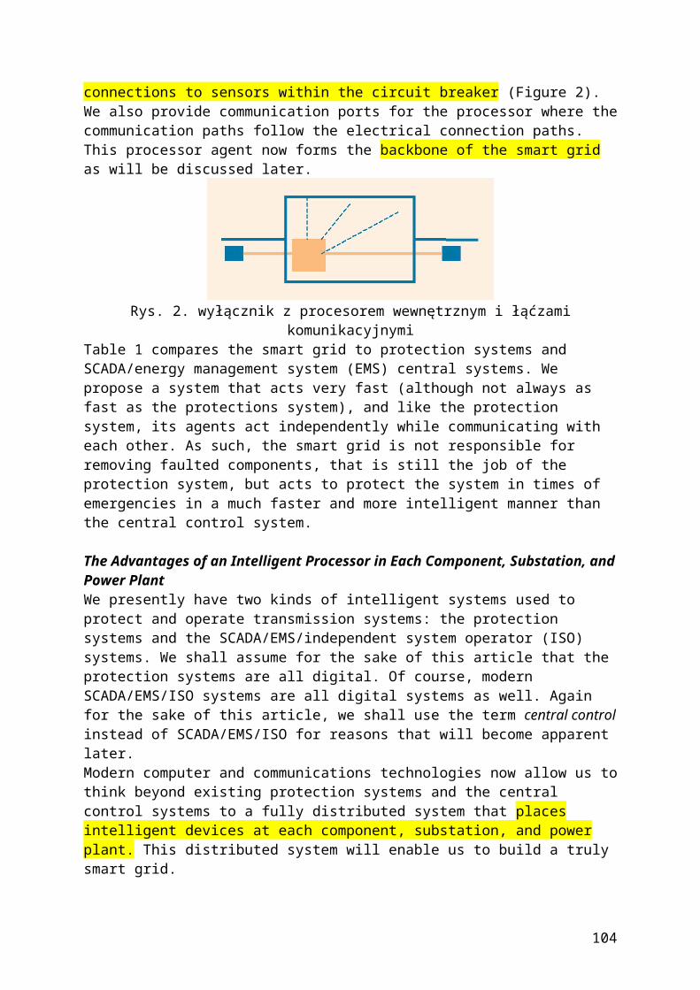
Challenges of Rapid EvolutionWhile the new attention focused on smart grid/metering projects highlighted above is a welcomed development with significant promise, the industry is facing considerable challenges that, if not heeded, may result in potentially massive project cost overruns and possible new stranded costs in under-performing or obsolete technologies. The most daunting challenge facing utilities during their rapid migration to a smart grid/metering business environment is that they are entering essentially uncharted territory with a number of serious pitfalls—and no one can predict how this fast moving business environment will evolve. Some analysts believe that the impact of distributed resources on central generation would be akin to the impact of personal computers on mainframe computing. While we can argue with the validity of the analogy, the only safe bet is that things will change, and will change rapidly and in ways that are hard to predict. This should be cause for concern because most managers, planners, and engineers in the utility industry are used to moving incrementally and deliberately along a predictable path. Their traditional business model is to migrate from state A to B, C, and D linearly. They are adapted to this type of transformation [Figure 1(a)].
figure 1. (a) From linear and static to (b) nonlinear and dynamic.This article argues that the transition to smart grid/metering environment will require flexible design, agility, and improvization necessitated by frequent and dramatic changes that are ill-suited for traditional utility-style projects. In this new environment, people, systems, solutions, and business processes must be dynamic and flexible, able to bend, shrink, or stretch in response to changes in technology, customer needs, prices, standards, policies, or other requirements. The need for flexibility is schematically shown in Figure 1(b), where transition from each state to the next is uncertain and may take one of many multiple paths.Static design and rigid, hard-wired, coded solutions—the traditional hallmarks of utility industry projects—could be obsolete before they are
104
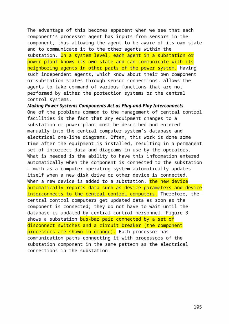
finished, essentially dated the day they are implemented. Some utilities are already experiencing rapid technological obsolescence and are trying to negotiate with the regulators to shorten the life of assets in AMI projects. Trying to upgrade and integrate old legacy systems in the dynamic and uncertain new environment will be futile technically, functionally, and economically.This article suggests that we should position our systems and solutions for a dynamic future, where products, services, and business processes frequently change, as is the case in many other industries such as telecommunications. We must also be mindful that as an industry, we are still building fixed, static, inflexible computer applications and interfaces that will be costly in such a dynamic future. It advocates a smarter approach to infrastructure upgrades where we would architect and integrate business processes in a flexible manner so that they can be agile and can dynamically adapt to changes. It advises the utilities to make “flexibility” a key requirement in their specifications as they procure new applications. It introduces a new framework, “smart integration,” that creates flexibility by integrating “dynamic applications” with “dynamic interfaces.” Finally, the article introduces the novel concept of a “flexibility test,” akin to performing seismic tests in the construction industry, that utilities could use to screen inflexible applications and interfaces. Some examples of dynamic applications and dynamic interfaces are presented.From Static to DynamicTo describe the serious challenge facing today’s utility managers, IT specialists, and business process professionals, take the case of the California independent system operator (CAISO). Significant sums went into designing its basic infrastructure from the ground up when California passed its restructuring law in 1996. These sophisticated systems were hard-wired and coded to perform specific tasks as envisioned by the original designers of the California market. The following quote from the Federal Energy Regulatory Commission (FERC) Technical Conference on CAISO MD02 Implementation (9 December 2002) captures the essence of the problem:Most of CAISO’s current market functions reside in a black box we call our scheduling application (SA). This black box is welded to the scheduling infrastructure (SI) making it difficult to change, or add to, the existing functionality. The design of these systems is monolithic (that is the complex interdependent elements of the systems make changes to one element impact others, there is a high degree of shared data elements and interfaces and data interactions are not open.) Monolithic design, although not inherently poor, is intended for systems that will not undergo significant change. In general, the systems development industry has evolved away from monolithic design toward open and component type design principles to drive flexibility and economies in system development and operations.Following the electricity crisis of 2000–2001, it became clear that the original market design was deficient in a number of dimensions. Moreover, to prevent a recurrence of many of the problems associated with gaming, market power abuse, and other issues, market rules, settlement procedures, and a host of other requirements were changed, including
105
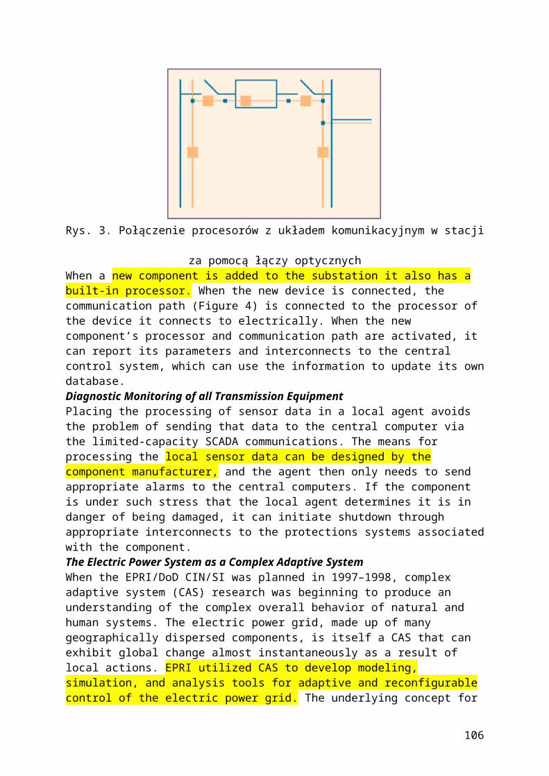
switching from zonal to nodal prices. These changes were to be incorporated in a massive undertaking called a market redesign technology upgrade (MRTU).The MRTU set out an ambitious plan to upgrade the technology and address the new requirements over a set period of time with a set budget. But the environment under which CAISO operates and the world beyond did not remain static for the MRTU project to be completed. The requirements evolved as the implementation progressed and the simulation results compelled the need to change the MRTU tariff and the new software applications.Confronted by frequent and unpredictable change, the MRTU project is behind schedule and over budget. While the new enterprise is likely to be more flexible than the original, it is not clear if it would be flexible enough to easily incorporate significant future changes such as those that may be driven by the increasing need for DR in California.
There are numerous examples from other ISOs and utility IT projects confronting essentially the same problem. Rigid, hard-wired systems that are difficult, if not impossible, to change do not work well in rapidly changing business, regulatory, and technical environments. The outcome is projects that are late, function marginally or poorly (if at all), and exceed their original budgets by wide margins. Moreover, even if they are made to work by the sheer tenacity of IT developers and vendors, they will face a similar challenge the next time a new requirement or change has to be incorporated, keeping the management, the customers, and the regulators perpetually frustrated.Winning When You Don’t Know the GameFor the sake of trivializing the problem, let’s say that an experienced football coach is told to prepare his team for a challenging game. He goes through the routine of getting the team ready and gets them the best uniforms and equipment. But when the team shows up at the field, he realizes that they must play a soccer match, not football. His players, all experts in passing, receiving, and carrying the football, will be penalized if they touch the ball in soccer. Moreover, their shoulder pads and helmets hamper their mobility on the field. Their practiced routines of passing and carrying are useless. In today’s business environment, the coach needs players who are agile and flexible—so they can play soccer, football or any other ball game—with versatility.An Example: A Dynamic Computer ApplicationBut how would this work in practice? That was the challenge posed by a recent research project funded by the California Institute for Energy & Environment (CIEE). Referring to the game analogy, the DRBizNet Project (for a DR business network), did not specify the exact nature of the game to be played, the specific rules of the game, the players, or other details (for more information on DRBizNet, see the “For Further Reading” section). It only described a conceptual scheme for developing, sending, receiving, verifying, and implementing signals in a fast, secure, and error-free environment among a number of participants in a DR program in California.
106
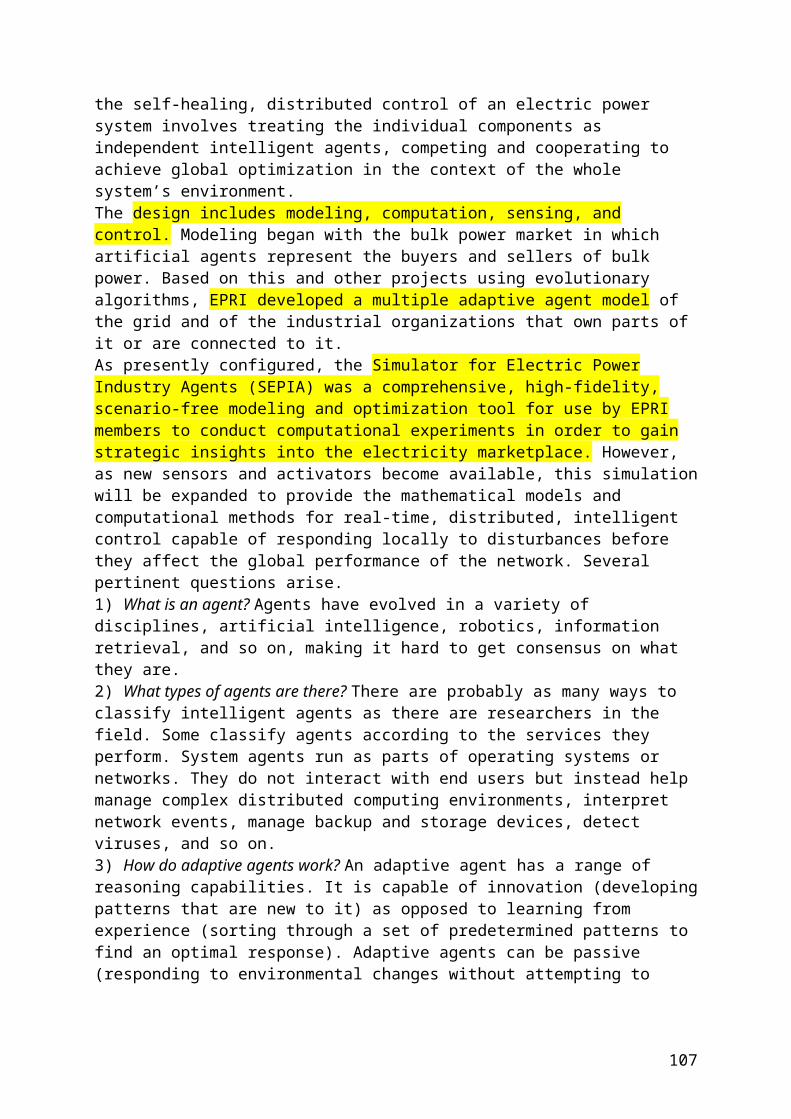
It was a challenging project precisely because so many of the critical details were intentionally unspecified. It was essentially asking the coach to prepare a team to play a ball game without saying what the game would be. Faced with this seemingly insurmountable challenge, the team was forced to define the requirements of the project at the highest level of abstraction so that the end product would be able to function under virtually any specific set of rules or specifications. The result was the definition of basic functionalities required in any DR project no matter who the participants were, how many, what specific systems or needs they had, or any other constraints. A great deal of flexibility was built into DRBizNet by building on top of flexible foundational technologies such as the standards-based service-oriented architecture (SOA), business process management, and intelligent agents (Figure 2).
figure 2. Bridging to an uncertain future with a dynamic demand response computer application built on flexible foundational technologies.At the conceptual level, this list provides what is needed to implement a DR program not knowing any of the details: an efficient system to register and identify participants in the DR program
a standardized set of protocols to send, receive, verify, and acknowledge signals among participants
a standard set of protocols to accept, reject, or modify notification signals for demand curtailment
a standard set of protocols for incentives offered to participants for engaging in DR programs
a standard set of protocols for keeping track of notification signals sent, received, accepted, rejected for record keeping, settlement, billing, auditing, and back-office systems
107
a highly secure and error-free environment for all of the above to take place in real-time and with high speeda flexible underlying IT infrastructure that could support all of the above and is capable of expanding or changing to accommodate frequent changes in the rules, the procedures, the number, and makeup of the participants or virtually anything else.
The DRBizNet Project succeeded precisely because it was designed from the ground up with flexibility in mind. The underlying IT infrastructure and business processes were defined to handle any DR tariff and market structure. The signals could come from CAISO and be sent to participating utilities who could pass it on to their customers, any aggregators, or other intermediaries. But if a different scheme was substituted, DRBizNet could still handle it.As long as the fundamentals remained the same—number of participants, registering, sending, receiving, verifying, accepting or rejecting standardized DR messages—the project could handle any change by virtue of simple configuration of its flexible building blocks. There was no need to change the computer application.To make this possible, quite a bit of intellectual capital had to go to thinking in abstract terms, to define the fundamental requirements on a conceptual level, and to provide built-in flexibility. As previously stated, this is in sharp contrast to many utility IT projects where the requirements of the desired end state are usually prespecified and the business environment is assumed to be static.Operational ChallengesManaging smart grid/metering projects is difficult due to the sheer size and complexity of the number of data points. For example, a typical DR project requires
secure and reliable communication and control among a potentially large number of participants
ability for participants to register and interact with one another in an error-free environment
bid, iterate, and interact to prices and response of other participants facility to schedule and implement the transactions that parties have
agreed to do protocols for measurement and verification of the above
automated processes for settlement, billing, collection, bookkeeping, and dispute resolution.
Similarly, managing a smart metering/pricing project requires offering different services and tariffs that vary by time of use and
potentially by type of application metering and meter data management services new systems for billing and settlement new customer-service applications capable of supporting the new
metering, pricing, and billing schemes.The traditional approach to design such new systems would be to specify a blueprint that includes a standard architecture for a group of applications that would supposedly provide the needed functionality. Historically, utilities would typically issue RFPs to procure the necessary applications or upgrading existing ones to provide incremental functionality.
108
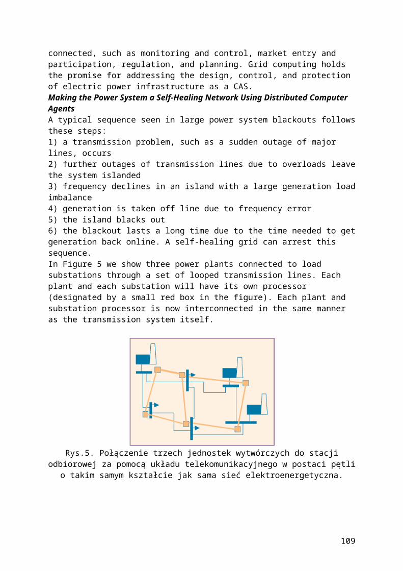
The vendors or the IT department would design and build static “data bridges” to connect these applications. The main shortcoming of this approach, as already pointed out, is that it represents a static view of a rapidly changing future, namely,
systems are built in deterministic ways, satisfying the requirements of the next phase
interfaces are built to connect these static systems nowhere in the specifications of the applications or interfaces is
there any explicit requirement for flexibility or adaptability to change (even if flexibility is mentioned, the industry does not have any convention or methodology for measuring or testing for flexibility).
Smart Business IntegrationHow to design, buy, and test flexible infrastructure? As the preceding DRBizNet example illustrated, including flexibility in the original project design is a challenging concept, requiring conceptual thinking at an abstract level. It would be akin to building a skyscraper that can withstand a massive earthquake or a bridge than can sway in the wind without collapsing. Just as such a flexible structure would require more advanced design and more resilience, flexible IT systems require more conceptual thinking up front.A comparison between the business planning environment in the utility and telco or airline sectors shows the contrast between flexible versus static design. Telcos and airlines can change their entire pricing structure in a matter of hours in response to changing business conditions or an advertising campaign by a competitor. For example, when a major airline announces that it will introduce a fuel surcharge or collect fees for checked luggage or on-board food service, the entire industry typically matches in a matter of hours.The same goes for a promotional fare or other marketing strategies. When one mobile phone company recently introduced a flat rate for mobile service, all others matched the offer instantly. If consumers demand new service options, such as a family plan for mobile phones, for text messaging, or other services, the industry can respond quickly. Utilities, by contrast, take months, if not longer, to introduce a new tariff or adjust an existing one, and this greatly hampers their ability to respond to consumer demand and changing requirements.How does one build a flexible infrastructure that can be more responsive to changing business environments and consumer needs? The basic recipe, which we call the “smart business integration” methodology, includes the following steps:
Define the basic products and services that consumers need at a conceptual level.
Identify the business processes that can support and deliver those products and services.
Break down the business processes into a set of services at a higher level of abstraction than is done today.
Provide the necessary infrastructure for integrating these services in a flexible way according to best practices in a service oriented architecture (SOA).
109
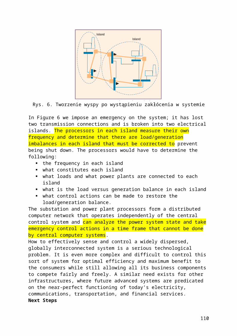
Buy or build applications for delivering the desired services in a dynamic and flexible way. (Business rules should not be hard coded. This can be accomplished by using business process management engines.)
Specify and build flexible interfaces to bridge data transfer among different applications making sure the interfaces are not tightly coupled with the applications. (Interfaces have to be a lot smarter than the dumb bridges of the past. They will be more expensive to build but will be independent of the applications if they are to be replaced.)
Manage business processes end-to-end with a business process management (BPM) software that coordinates among different applications.
Simplify the connections between applications and minimize coupling through an enterprise application integration (EAI) architecture.
Use smart technologies such as complex event processing (CEP) to analyze the events as they occur and use the insight obtained to automatically modify business processes dynamically.
Investing in Dynamic InterfacesThe commercial systems integration (CSI) framework developed by the Electric Reliability Council of Texas (ERCOT) provides an example of flexible interfaces. The CSI framework was designed to bridge the gap between several market applications and the settlement application. In this case, the challenge was to design the interface before the applications were fully designed. To allow for such flexibility, the concepts described above were applied to design a highly configurable interface built for change so that when business rules change, they do not impact the base framework. In the long run, such built-in flexibility is likely to save considerable money in terms of avoided change orders.The Flexibility TestHaving described what is meant by flexible infrastructure and how to build it, one must focus on testing for flexibility, just as technicians test new cars for crash resistance or engineers test new building designs for withstanding earthquakes. The utility industry needs to define new tests and new standards testing software flexibility. Today we only test software for conformance to prespecified requirements and the ability to take more volume or to work faster. Standards tests currently used include
functionality tests availability tests performance tests security tests volume tests integration tests.
We, as an industry, should define new tests to measure how flexible an application is. Can it, for example, handle a different set of requirements or withstand the equivalent of an 8.0 earthquake? Can the vendors of various components of a complicated IT project demonstrate that they can quickly and easily reconfigure the business processes and business rules in a given application? If one application in a chain of applications was
110

changed or replaced, can the remaining applications perform with limited effort? These are among the issues that will make a big difference in how well the overall framework will perform. Ultimately, we must ask each vendor two key questions:
How fast and at what cost can you change an application? How fast and at what cost can you change an interface?
This is not an easy thing to achieve, partly because the engineers procuring the systems are not used to specifying and demanding flexible applications, and also because many vendors serving the utility industry are not used to developing and delivering this type of software. But since the most important permanent asset in a complicated IT project is the underlying integrated infrastructure, every effort and every precaution must be taken to end up with such a solution at the end. The extra up-front effort will certainly be worth it if it results in a platform that allows us to offer new products and services and can support new business processes or changes to existing ones.Smart companies incorporate flexibility in their requirements and test for flexibility. As an example, when the PJM Interconnection decided to replace its existing DR system with one that can keep up with the changing business rules, they identified “architecture flexibility” as a key requirement. They also tested for flexibility by asking vendors to show that the software can be quickly configured to accommodate major changes to business processes and business rules. Flexibility played a key factor in their procurement process. Smart investment in flexibility is likely to pay off handsomely in the long run.Moving Away from the Static World of Static DesignsAs the utility industry evolves, yesterday’s static world where we moved incrementally from the current state to a well defined future state where new system requirements could be specified with accuracy and certainty has come to an end. We are entering into a dynamic era where the only certainty is change. Under these circumstances, utilities must position themselves to be flexible and agile—being able to react to change quickly, being able to respond to new customer needs, and being able to take advantage of fast evolvingtechnological opportunities and innovations.In this new era, we need flexible infrastructure— bridges and skyscrapers made from flexible material and not unbending concrete or rigid steel. Components used in new projects must be defined and designed to dynamically adapt to change. As highlighted in this article, inflexible/ static components would have a short life at best in a rapidly evolving environment. The transition from static to dynamic will be a difficult one for utilities and vendors that are not used to dealing with rapid change and uncertain design features (not all software used by utilities is inflexible; e.g., many commercial enterprise resource planning systems used by utilities are built for use in multiple industries and are quite flexible). But the alternative is worse: a graveyard of stranded investments—systems and solutions that under-perform and are obsolete faster than they can be replaced (Figure 3). Some utilities are already confronting the problems associated with premature obsolescence in advanced metering projects. Ultimately, customers have to pay for the mistakes.
111

It will be more expensive to build flexible infrastructures than static ones. But the value proposition will be large. The sooner we start investing in flexibility, the sooner we can start saving and avoiding rapid technological obsolescence.For Further Reading
Vojdani, “How to get more response from demand response,” Electr. J., vol. 19, no. 8, Oct. 2006. Vojdani, “The Missing Link, Special edition on demand response,” Public Utilities Fortnightly, Mar. 2007. Vojdani, S. Neumann, and G. Yee, “California demand response business network,” in Proc. DistribuTech 2006. A. Vojdani, “Applying workflow technologies to integrate utility business processes,” in Proc. DistribuTech 2005. Vojdani, “Tools for real-time business integration and collaboration,” IEEE Trans. Power Syst. vol. 18, no. 2, pp. 555–562, May 2003. D. Luckham, The Power of Events: An Introduction to Complex Event Processing in Distributed Enterprise Systems. Reading, MA: Addison-Wesley, 2002.
Utility Experience with Developing a Smart Grid Roadmap M. McGranaghan, Senior Member IEEE, D. Von Dollen, Senior Member IEEE, P. Myrda, SeniorMember, IEEE, E. Gunther, Senior Member, IEEE
©2008 IEEE
{Kolejne praktyczne rozwiązanie tego co opisali Ilic i spółka - Preventing Future Blackouts by Means of Enhanced Electric Power Systems Control: From Complexity to Order }
Vision 2020 - Security of the network operation today and in the future. German experiencesKrebs, R.1; Buchholz, B. M.1; Styczynski, Z. A.2; Rudion, K.2; Heyde, C.2; Sassnick, Y.3©2008 IEEE.
{Wizja przyszłości SEE wg Styczyńskiego i Spółki}……………
V. POWER SYSTEM OPERATION - FUTUREThe development plans of the EU for the electricity sector include a very high share of generating units connected to the distribution system. Hence, the distribution system will play an increasing role in providing system services. Fig. 8 shows the evolution of transferring parts of the responsibility for the system services from the transmission side to the distribution side. In order for the distribution systems to accomplish these tasks from Fig. 8, new and innovative operation strategies are currently being researched and developed. The most common names in this area are ‘virtual power plants’ [11] and ‘smart grids’[12]. In the seventh research framework program of the EU the topic smart grids has a very high priority. The target of such approaches is to optimize the use of energy in economical, technical, ecological and reliability constrains.
112

Fig. 8 Schematic presentation of responsibilities for system services now and inthe future [18].
All approaches have in common, that they rely on a high degree of observability and controllability. This is not given now for the distribution systems. Observability means the exact knowledge about the current system state using measurements from all the influencing elements. Only by knowing the system states, safety margins and optimized operation strategies can be calculated. In order to realize the optimized operation strategies, the controllability is needed. Both observability and controllability are depending on communication. The communication system is currently the most discussed burden towards the virtual power plants or smart grids. The amount of exchanged data can be huge and the security constraint is very important [14]. An additional aspect concerning the information and communication technologies (ICT) is a uniform communication standard, like e.g. IEC 61850 [13].Provided that a uniform communication technology will reach to all the market players, the approach of the future power system operation could look like in Fig. 9. With the control possibility of a large number of small generators, the distribution system operators (DSOs) should support the security of the system operation in the same way as the TSOs with the central power plants. In addition as also depicted in Fig. 8 the ability of islanding operation will lead to even higher security and availability of power supply to the customers. With an increasing degree of communication, also the loads could take part of the system control with the so called demand side management (DSM).One other approach towards a more safe and reliable power supply is the dynamic security assessment (DSA). The facts described in section III show that the power systems are operated very near to the security limits. The reason for this is that, on the one hand, the liberalization and unbundling resulted in a more competitive environment where investment decisions have become harder, and on the other hand, the process of planning, clearance and commissioning of new overhead lines usually takes 10 to 20 years.
113
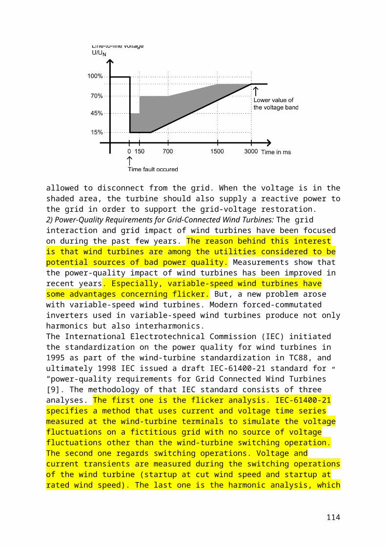
Fig. 9 Future operation of power systems compared to the state of the art.
Operating the power system near to its limits, of course, makes the loss of load more probable. In order to maintain the high level of reliability, the current network operation strategies have to be changed towards new, innovative strategies. These new strategies should take into account the security evaluation of the actual network state. The usual methodology of security assessment systems has a stationary character and is performed offline. Such an approach is, however, no more sufficient for systems with a high number of dispersed generation units with an intermittent character. Therefore, there is a need for DSA systems [15] which consider the additional aspects, like the influence of controllers, on the security and stability of the power system (see Fig. 10). This evaluation is done on the basis of the calculated security margins for different contingencies. This margin would now allow for operating the network, never exceeding a certain probability of loss of load.The main tasks of such a DSA system are:
monitoring, margin calculation, visualization.
Again as for the virtual power plant, the communication is an important aspect in monitoring power systems. A high degree of observability is essential for a fast state estimation as well as appropriate reacting to security problems. The development of wide-area monitoring systems that are based on phasor measurement units (PMU), allows for better observation and coordination of large power systems due to the time-synchronized measurements [16]. Margin calculation is another important aspect of the DSA.
114

Fig. 10 Structure of a DSA system.
New, fast algorithms have to be developed in order to process as many contingencies as possible. Therefore, the margin calculation algorithms themselves have to be improved as well as the selecting and ranking of the contingencies which have to be evaluated [17]. The third important aspect is the visualization of the calculations in order to help the staff in the control room during the decision process. They usually do not have much time to take the decisions, but the information that is important is becoming more and more complex as the number of control elements rises (DGs, FACTS, SVC etc.). Hence, an innovative visualization scheme is needed that can use all senses of the control room personnel in order to manage the information flow from the technical equipment to the people in charge.
VI. CONCLUSIONSIn this paper the current situation in German and European power systems was described. It was shown, that the approved practice in the operation of power systems is becoming increasingly problematic under a liberalized economic situation. Also, the trend towards an energy mix of centralized and decentralized power stations makes the operation of the power systems more and more complicated. In recent years the regulations have had to be modified, because the rising number of DGs has caused security problems.In order to withstand the economical pressure on the one side and the reliability constraint on the other side, new, innovative strategies for network operation have to be established. Dynamic security assessment systems are found to be the appropriate tool to combine the approaches concerning virtual power plants and to operate the power system closer to its limits, but with a known probability of loss of load.
[11] Rudion, K.; Orths, A.; Lebioda, A.; Styczynski, Z.:Wind Farms with DFIG as Virtual Power Plants. Proceedings of the Fifth International Workshop on Large-Scale Integration of Wind Power and Transmission Networks for Offshore Wind Farms, Glasgow, Scotland, 2005. [12] www.smart.grids.eu, 2008. [13] Bucholz B.M., Styczynski Z.A., Communication Requirements and Solutions for Secure Power System Operation, IEEE Power Engineering Society General Meeting, 2006. [14] Bucholz B.M., Styczynski Z.A., New tasks create new solutions for communication in distribution systems, IEEE Power Engineering Society General Meeting, 2006.
115
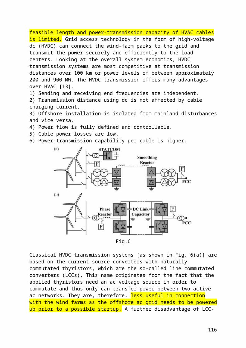
[15] Lerch E., Ruhle O., Dynamic Security Assessment to protect systems after severe fault situations, International Conference on Power System Technology 2006. PowerCon 2006. [16] Dzienis C., Styczynski Z.A., Komarnicki P., A Method for Optimally Localizing Power Quality Monitoring Devices in Power Systems, Proceedings of the Power Tech 2007, Switzerland, Lausanne, 2007. [17] Krebs R., Ruhle O., Bizjak G., Derin U., Vision 2020 Dynamic Security Assessment in Teal Time Environment, proposed paper for the IEEE General Meeting 2008 in Pittsburgh, USA, 2008. [18] Bucholz B.M., Netzintegration verteilter und erneuerbarer Erzeuger im Kontext der Smart Grid – Strategie der EU, VWEW Fachtagung, Fulda, 2006.
116