Non-invasive inspection of heat exchanger tubeshosting2997635.az.pl/pliki/OAL/2013-12-05-64.pdf ·...
6
64 Przegląd sPawalnictwa 12/2013 Hans Felius Non-invasive inspection of heat exchanger tubes Bezinwazyjna metoda badania wymienników ciepła Hans Felius Streszczenie Dwie znane metody inspekcji rur i przewodów ruro- wych to Acoustic Pulse Reflectometry (APR) oraz Guide- dWaves(GW). Obie metody oparte są na próbkowaniu rur/ przewodów za pomocą długich fal akustycznych, albo za pośrednictwem powietrza w rurach (APR) lub ścian ruro- wych(GW). Obie metody mają taką zaletę że, umożliwiają bardzo krótki czas kontroli, rzędu 10 sekund na rurę. Po- nadto, każda z tych metod ma wady i zalety komplementar- ne. APR dla przykładu może wykryć blokad i bardzo małe kratery, ale jest niewrażliwa na wady na średnicy zewnętrz- nej (OD).Metoda GW, z drugiej strony, może wykryć błędy na średnicy zewnętrznej (OD), ale nie może z łatwością odróżnić wżerów od otworów przelotowych. W przeciwień- stwie do APR, która jest stosowana do inspekcji rur przez kilka lat, GW był używany głównie do przesiewania aplikacji w rur o dużej średnicy. W tym artykule najpierw przedstawi- my kilka wdrożeń i zastosowań GW, które mogą pasować do rurek tak małych, jak 3/4” i być zdolne do wykrywania, klasyfikacjii wielkości wad. Będzie to implementacja Ultra- sonic Reflectometry Pulse(UPR). Następnie pokażemy, jak łączyć układy zawierające zarówno APR oraz UPR w jed- no kompleksowe stanowisko do inspekcji rur, umożliwiają- ce bardzo szybką kontrolę i zdolne do wykrywania wszyst- kich typowych uszkodzeń rur. Abstract Two well-known methods for inspection of tubes and pipes are Acoustic Pulse Reflectometry (APR) and Guided Waves (GW). Both are based on probing the tubes/pipes using long range acoustic waves, either through the air in the tubes (APR) or the tube walls (GW). Both methods share the advantage of being non-traversing, enabling very short inspection times, on the order of 10 seconds per tube. In addition, each method has complementary advantages and disadvantages. APR for example can de- tect blockages and very small pinholes but is in sensitive to Outer Diameter (OD) defects. GW, on the other hand, can detect OD faults but can not easily distinguish pitting from through-holes. As opposed to APR, which has been applied to tube inspection for several years, GW has been used mainly for screening applications in large diameter pipes. In this paper we firs present several recent devel- opments in GW, giving an implementation that can fit into tubes as small as 3/4” and capable of detecting, classi- fication and sizing of defects. We term this implementa- tion Ultrasonic Pulse Reflectometry (UPR). We then show how a combined system containing both APR and UPR in a single probe provides a comprehensive solution to tube inspection, enabling very rapid inspection and capable of detecting all typical tube defects. Introduction Heat exchanger tube inspection is an issue that has been around for as long as heat exchangers them- selves. Over the many decades since heat exchangers have first seen service, inspection technologies have evolved considerably. However, even today all conven- tional methods share a common trait: they all rely on traversing each tube to be inspected with a physical probe. There are several drawbacks to this approach: 1. Speed: pushing a probe all the way up and down a tube is time consuming, limiting the speed with which the tubes can be inspected. 2. Wear and tear: probes and cables experience vary- ing degrees of wear as they are dragged through a tube, depending mainly on the surface roughness of the tubes being examined, which can be quite se- vere. 3. Difficulties in navigating bends: Many heat ex- changers are composed of u-tubes, and negotiating a probe through them can be difficult to impossible. Flexible probes intended for such tubes are much more expensive and are still limited in the radius of curvature which they can go through.
Transcript of Non-invasive inspection of heat exchanger tubeshosting2997635.az.pl/pliki/OAL/2013-12-05-64.pdf ·...
64 Przegląd sPawalnictwa 12/2013
Hans Felius
Non-invasive inspection of heat exchanger tubes
Bezinwazyjna metoda badania wymienników ciepła
Hans Felius
Streszczenie
Dwie znane metody inspekcji rur i przewodów ruro-wych to Acoustic Pulse Reflectometry (APR) oraz Guide-dWaves(GW). Obie metody oparte są na próbkowaniu rur/przewodów za pomocą długich fal akustycznych, albo za pośrednictwem powietrza w rurach (APR) lub ścian ruro-wych(GW). Obie metody mają taką zaletę że, umożliwiają bardzo krótki czas kontroli, rzędu 10 sekund na rurę. Po-nadto, każda z tych metod ma wady i zalety komplementar-ne. APR dla przykładu może wykryć blokad i bardzo małe kratery, ale jest niewrażliwa na wady na średnicy zewnętrz-nej (OD).Metoda GW, z drugiej strony, może wykryć błędy na średnicy zewnętrznej (OD), ale nie może z łatwością odróżnić wżerów od otworów przelotowych. W przeciwień-stwie do APR, która jest stosowana do inspekcji rur przez kilka lat, GW był używany głównie do przesiewania aplikacji w rur o dużej średnicy. W tym artykule najpierw przedstawi-my kilka wdrożeń i zastosowań GW, które mogą pasować do rurek tak małych, jak 3/4” i być zdolne do wykrywania, klasyfikacjii wielkości wad. Będzie to implementacja Ultra-sonic Reflectometry Pulse(UPR). Następnie pokażemy, jak łączyć układy zawierające zarówno APR oraz UPR w jed-no kompleksowe stanowisko do inspekcji rur, umożliwiają-ce bardzo szybką kontrolę i zdolne do wykrywania wszyst-kich typowych uszkodzeń rur.
AbstractTwo well-known methods for inspection of tubes and
pipes are Acoustic Pulse Reflectometry (APR) and Guided Waves (GW). Both are based on probing the tubes/pipes using long range acoustic waves, either through the air in the tubes (APR) or the tube walls (GW). Both methods share the advantage of being non-traversing, enabling very short inspection times, on the order of 10 seconds per tube. In addition, each method has complementary advantages and disadvantages. APR for example can de-tect blockages and very small pinholes but is in sensitive to Outer Diameter (OD) defects. GW, on the other hand, can detect OD faults but can not easily distinguish pitting from through-holes. As opposed to APR, which has been applied to tube inspection for several years, GW has been used mainly for screening applications in large diameter pipes. In this paper we firs present several recent devel-opments in GW, giving an implementation that can fit into tubes as small as 3/4” and capable of detecting, classi-fication and sizing of defects. We term this implementa-tion Ultrasonic Pulse Reflectometry (UPR). We then show how a combined system containing both APR and UPR in a single probe provides a comprehensive solution to tube inspection, enabling very rapid inspection and capable of detecting all typical tube defects.
Introduction
Heat exchanger tube inspection is an issue that has been around for as long as heat exchangers them-selves. Over the many decades since heat exchangers have first seen service, inspection technologies have evolved considerably. However, even today all conven-tional methods share a common trait: they all rely on traversing each tube to be inspected with a physical probe. There are several drawbacks to this approach:
1. Speed: pushing a probe all the way up and down a tube is time consuming, limiting the speed with which the tubes can be inspected.
2. Wear and tear: probes and cables experience vary-ing degrees of wear as they are dragged through a tube, depending mainly on the surface roughness of the tubes being examined, which can be quite se-vere.
3. Difficulties in navigating bends: Many heat ex-changers are composed of u-tubes, and negotiating a probe through them can be difficult to impossible. Flexible probes intended for such tubes are much more expensive and are still limited in the radius of curvature which they can go through.
65Przegląd sPawalnictwa 12/2013
4. Susceptibility and sensitivity to restrictions: This is in fact a twofold problem. Unforeseen restrictions, caused by scale for example, can prevent a probe from advancing, or even cause it to become stuck. On the other hand, none of the traversing methods, even when they can traverse restrictions, have the ability to detect and quantify them, in order to assess cleanliness. The most widespread techniques employing travers-
ing probes are based on electromagnetic principles (Eddy Current, Magnetic Flux Leakage, Remote Field) or ultrasound. In addition to the drawbacks cited above, these individual methods have other limitations also. Ultrasound, for example, which is commonly consid-ered to be the most accurate of the traversing meth-ods, cannot detect pinholes of less than approximately 2 mm in diameter, aside from being the slowest of these techniques.
Non-traversing approaches Any attempt to inspect a tube without a probe must
necessarily rely on propagating some form of wave throughout the length of the tube – either mechani-cal or electromagnetic. Whenever such a wave en-counters any form of non-uniformity in the tube, this will cause scattering, generating waves that propagate back down the tube. If these scattered waves can be recorded and interpreted correctly, the non-uniformity that caused them can be characterized, whether it is a design feature or a defect. Generically this method is referred to as Reflectometry, and when the original wave is a pulse, it is called Pulse Reflectometry (PR).
Several attempts to implement methods based on reflectometry have appeared in the scientific literature, some of them reaching mature enough stages to be implemented commercially. A short review of these fol-lows.
The least explored reflectometry method appears to be based on electromagnetic waves. Aside from a con-ference presentation, the present author has not found any citable material on this technique.
Reflectometry based on propagating ultrasonic waves within tube or pipe walls has become to be known as Guided Waves (GW). This method has met with reasonable commercial success when used for pipe inspection, and has seen some development for heat exchanger tube inspection in recent years. There are few publications available on this subject [1], and therefore limited information available regarding such system’s capabilities.
Lastly, reflectometry based on propagating acoustic waves in the air enclosed by the tubes appears to be the most researched reflectometry method, and the earliest to be implemented. Termed Acoustic Pulse Reflectometry (APR), it has seen various applications (from musical instrument characterization to leak de-tection) in research laboratories for several decades [2-4]. One commercial implementation has been in use to detect leaks and obstructions in pipes and tubes,
though it appears to be less geared towards heat ex-changers [2]. Work by the present author and his col-laborators has also led to a commercial implementation targeted solely towards heat exchangers [4].
Even the more successful reflectometry techniques described above have limitations which make it difficult for them to compete successfully with the more con-ventional methods. APR, for example, by its nature, cannot detect OD defects, even though it is probably more sensitive to pinholes (down to about 0.5 mm in di-ameter) than any other tube inspection technique. GW, on the other hand, cannot detect restrictions and block-ages, and has difficulties in distinguishing between wall loss and through holes. However, the capabilities of the latter two methods are in fact complementary to a large degree. It was therefore decided to examine the pos-sibility of a combined inspection system, carrying out APR and GW measurements simultaneously. This sys-tem is described below.
APR revisited
APR has been described extensively in many aca-demic papers over the past several decades. Its im-plementation as an NDT tool has been described in several papers by the author and his collaborators [2, 4], and it has also been the subject of at least two in-dependent evaluations. For completeness, the basics of this method are repeated here.
APR principlesAPR is centred on generating a short pulse in the
air enclosed by the tube under inspection, and then re-cording any scattered waves propagating back up the tube. Though this may sound relatively simple, many challenges arise in practical implementation. In order to detect small defects, a high level of Signal to Noise Ratio (SNR) is necessary. However, in order to obtain good axial resolution, a very narrow pulse is desirable. These two requirements are conflicting, since a narrow pulse will have lower energy than a wide one. One pos-sibility to increase SNR is to repeat the measurement of a single tube many times and average these measure-ments, however this will increase measurement time considerably. Ultimately, there are two methods that can combine the best of both worlds: measuring with a frequency sweep, or using Maximum Length Se-quences (MLS). The latter technique involves transmit-ting a pseudo random sequence of positive and nega-tive pulses over several seconds. When the reflections are recorded, correlating them with the transmitted gives the pulse response, albeit at a much higher SNR than what can be obtained by a single measurement.
As mentioned above, axial resolution is improved by narrowing the excitation pulse, which translates in the frequency domain to extending the bandwidth. However there are limits on this bandwidth. The first,
66 Przegląd sPawalnictwa 12/2013
which is less restrictive, is that bandwidth must be kept below the cutoff frequency of the higher order modes, otherwise the wave inside the tube ceases to be a plane wave and measuring it becomes prohibitively complex. the second limitation on bandwidth is due to attenua-tion. As the acoustic pulse propagates down the tube, it is gradually attenuated due to the friction with the tube walls, with high frequencies attenuating faster than low frequencies. Thus, for distant defects, the effective SNR gradually decreases, as well as the bandwidth. To some extent, this effect can be countered by increas-ing overall amplitude, and through pulse shaping tech-niques, to optimize the results once the diameter and length of the tube being inspected are known.
APR signal interpretation Interpretation of APR signals is relatively straight-
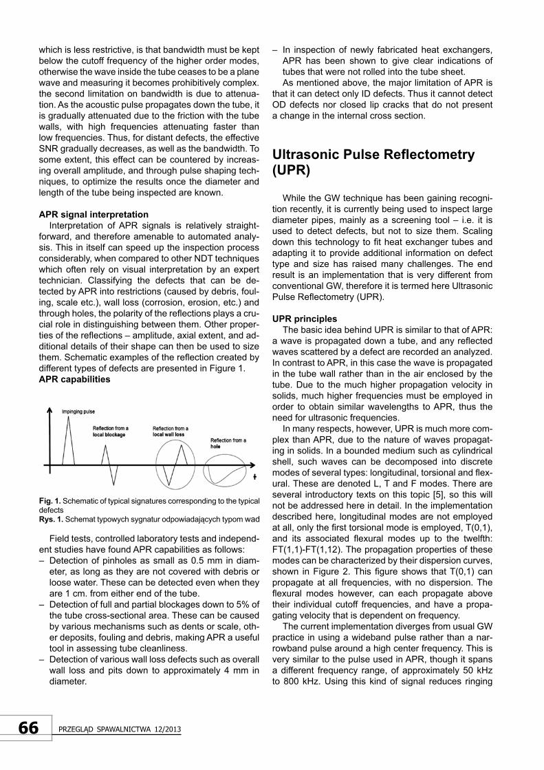
forward, and therefore amenable to automated analy-sis. This in itself can speed up the inspection process considerably, when compared to other NDT techniques which often rely on visual interpretation by an expert technician. Classifying the defects that can be de-tected by APR into restrictions (caused by debris, foul-ing, scale etc.), wall loss (corrosion, erosion, etc.) and through holes, the polarity of the reflections plays a cru-cial role in distinguishing between them. Other proper-ties of the reflections – amplitude, axial extent, and ad-ditional details of their shape can then be used to size them. Schematic examples of the reflection created by different types of defects are presented in Figure 1. APR capabilities
Fig. 1. Schematic of typical signatures corresponding to the typical defectsRys. 1. Schemat typowych sygnatur odpowiadających typom wad
Field tests, controlled laboratory tests and independ-ent studies have found APR capabilities as follows: – Detection of pinholes as small as 0.5 mm in diam-
eter, as long as they are not covered with debris or loose water. These can be detected even when they are 1 cm. from either end of the tube.
– Detection of full and partial blockages down to 5% of the tube cross-sectional area. These can be caused by various mechanisms such as dents or scale, oth-er deposits, fouling and debris, making APR a useful tool in assessing tube cleanliness.
– Detection of various wall loss defects such as overall wall loss and pits down to approximately 4 mm in diameter.
– In inspection of newly fabricated heat exchangers, APR has been shown to give clear indications of tubes that were not rolled into the tube sheet. As mentioned above, the major limitation of APR is
that it can detect only ID defects. Thus it cannot detect OD defects nor closed lip cracks that do not present a change in the internal cross section.
Ultrasonic Pulse Reflectometry (UPR)
While the GW technique has been gaining recogni-tion recently, it is currently being used to inspect large diameter pipes, mainly as a screening tool – i.e. it is used to detect defects, but not to size them. Scaling down this technology to fit heat exchanger tubes and adapting it to provide additional information on defect type and size has raised many challenges. The end result is an implementation that is very different from conventional GW, therefore it is termed here Ultrasonic Pulse Reflectometry (UPR).
UPR principles The basic idea behind UPR is similar to that of APR:
a wave is propagated down a tube, and any reflected waves scattered by a defect are recorded an analyzed. In contrast to APR, in this case the wave is propagated in the tube wall rather than in the air enclosed by the tube. Due to the much higher propagation velocity in solids, much higher frequencies must be employed in order to obtain similar wavelengths to APR, thus the need for ultrasonic frequencies.
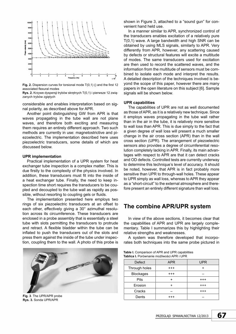
In many respects, however, UPR is much more com-plex than APR, due to the nature of waves propagat-ing in solids. In a bounded medium such as cylindrical shell, such waves can be decomposed into discrete modes of several types: longitudinal, torsional and flex-ural. These are denoted L, T and F modes. There are several introductory texts on this topic [5], so this will not be addressed here in detail. In the implementation described here, longitudinal modes are not employed at all, only the first torsional mode is employed, T(0,1), and its associated flexural modes up to the twelfth: FT(1,1)-FT(1,12). The propagation properties of these modes can be characterized by their dispersion curves, shown in Figure 2. This figure shows that T(0,1) can propagate at all frequencies, with no dispersion. The flexural modes however, can each propagate above their individual cutoff frequencies, and have a propa-gating velocity that is dependent on frequency.
The current implementation diverges from usual GW practice in using a wideband pulse rather than a nar-rowband pulse around a high center frequency. This is very similar to the pulse used in APR, though it spans a different frequency range, of approximately 50 kHz to 800 kHz. Using this kind of signal reduces ringing
67Przegląd sPawalnictwa 12/2013
considerable and enables interpretation based on sig-nal polarity, as described above for APR.
Another point distinguishing GW from APR is that waves propagating in the tube wall are not plane waves, and therefore both exciting and measuring them requires an entirely different approach. Two such methods are currently in use: magnetostrictive and pi-ezoelectric. The implementation described here uses piezoelectric transducers, some details of which are discussed below.
UPR implementation Practical implementation of a UPR system for heat
exchanger tube inspection is a complex matter. This is due firstly to the complexity of the physics involved. In addition, these transducers must fit into the inside of a heat exchanger tube. Finally, the need to keep in-spection time short requires the transducers to be cou-pled and decoupled to the tube wall as rapidly as pos-sible, without resorting to coupling gels or fluids.
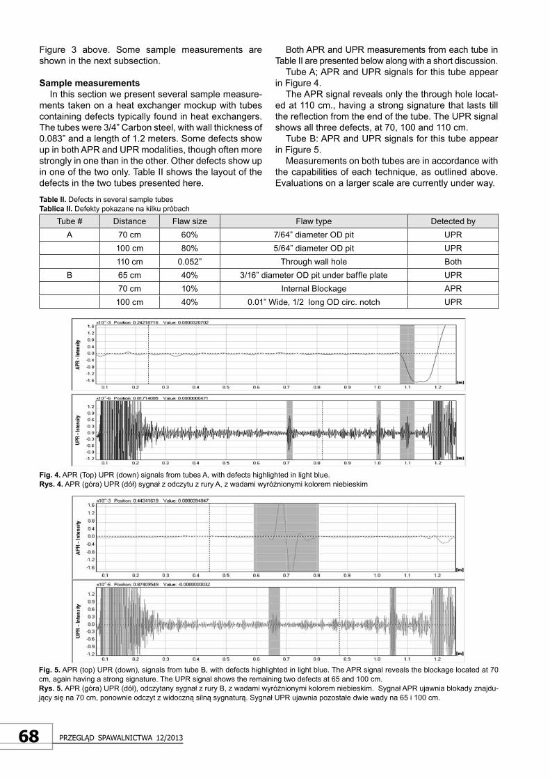
The implementation presented here employs two rings of six piezoelectric transducers at an offset to each other, effectively giving a 30° azimuthal resolu-tion across its circumference. These transducers are enclosed in a probe assembly that is essentially a steel tube with slots permitting the transducers to protrude and retract. A flexible bladder within the tube can be inflated to push the transducers out of the slots and press them against the inside of the tube under inspec-tion, coupling them to the wall. A photo of this probe is
Fig. 2. Dispersion curves for torsional mode T(0,1) () and the first 12 associated flexural modesRys. 2. Krzywe dyspersji trybów skrętnych T(0,1) i pierwsze 12 zwią-zanych trybów zgiętych
shown in Figure 3, attached to a “sound gun” for con-venient hand held use.
In a manner similar to APR, synchronized control of the transducers enables excitation of a relatively pure T(0,1) wave. A large bandwidth and high SNR can be obtained by using MLS signals, similarly to APR. Very differently from APR, however, any scattering caused by defects or structural features will excite a multitude of modes. The same transducers used for excitation are then used to record the scattered waves, and the information from the multitude of sensors must be com-bined to isolate each mode and interpret the results. A detailed description of the techniques involved is be-yond the scope of this paper, however there are many papers in the open literature on this subject [6]. Sample signals will be shown below.
UPR capabilities The capabilities of UPR are not as well documented
as those of APR, as it is a relatively new technique. Since it employs waves propagating in the tube wall rather than in the air in the tube, it is relatively more sensitive to wall loss than APR. This is due simply to the fact that a given degree of wall loss will present a much smaller change in the air cross section (APR) than in the wall cross section (UPR). The arrangement of piezoelectric sensors also provides a degree of circumferential reso-lution completely lacking in APR. Finally, its main advan-tages with respect to APR are that it can detect cracks and OD defects. Controlled tests are currently underway to determine this technique’s level of accuracy. It should be noted, however, that APR is in fact probably more sensitive than UPR to through-wall holes. These appear to UPR simply as wall loss, whereas to APR they appear as a “short-circuit” to the external atmosphere and there-fore present an entirely different signature than wall loss.
The combine APR/UPR system
In view of the above sections, it becomes clear that the capabilities of APR and UPR are largely comple-mentary. Table I summarizes this by highlighting their relative strengths and weaknesses.
A system was therefore developed that incorpo-rates both techniques into the same probe pictured in
Fig. 3. The UPR/APR probeRys. 3. Sonda UPR/APR
Defect APR UPRThrough holes +++ +
Blockages +++ –Pits + +++
Erosion + +++Cracks – +++ Dents +++ –
Table I. Comparison of APR and UPR capabilitiesTablica I. Porównanie możliwości APR i UPR
68 Przegląd sPawalnictwa 12/2013
Figure 3 above. Some sample measurements are shown in the next subsection.
Sample measurements In this section we present several sample measure-
ments taken on a heat exchanger mockup with tubes containing defects typically found in heat exchangers. The tubes were 3/4” Carbon steel, with wall thickness of 0.083” and a length of 1.2 meters. Some defects show up in both APR and UPR modalities, though often more strongly in one than in the other. Other defects show up in one of the two only. Table II shows the layout of the defects in the two tubes presented here.
Tube # Distance Flaw size Flaw type Detected byA 70 cm 60% 7/64” diameter OD pit UPR
100 cm 80% 5/64” diameter OD pit UPR110 cm 0.052” Through wall hole Both
B 65 cm 40% 3/16” diameter OD pit under baffle plate UPR70 cm 10% Internal Blockage APR
100 cm 40% 0.01” Wide, 1/2 long OD circ. notch UPR
Table II. Defects in several sample tubes Tablica II. Defekty pokazane na kilku próbach
Both APR and UPR measurements from each tube in Table II are presented below along with a short discussion.
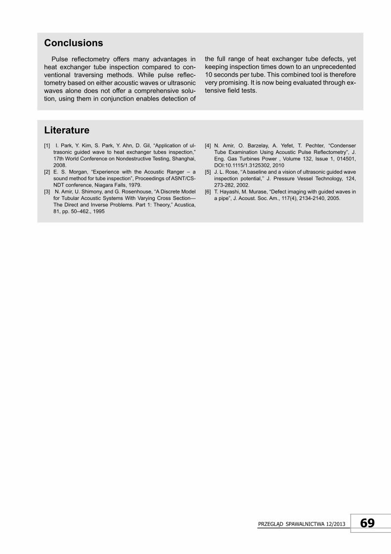
Tube A; APR and UPR signals for this tube appear in Figure 4.
The APR signal reveals only the through hole locat-ed at 110 cm., having a strong signature that lasts till the reflection from the end of the tube. The UPR signal shows all three defects, at 70, 100 and 110 cm.
Tube B: APR and UPR signals for this tube appear in Figure 5.
Measurements on both tubes are in accordance with the capabilities of each technique, as outlined above. Evaluations on a larger scale are currently under way.
Fig. 4. APR (Top) UPR (down) signals from tubes A, with defects highlighted in light blue.Rys. 4. APR (góra) UPR (dół) sygnał z odczytu z rury A, z wadami wyróżnionymi kolorem niebieskim
Fig. 5. APR (top) UPR (down), signals from tube B, with defects highlighted in light blue. The APR signal reveals the blockage located at 70 cm, again having a strong signature. The UPR signal shows the remaining two defects at 65 and 100 cm.Rys. 5. APR (góra) UPR (dół), odczytany sygnał z rury B, z wadami wyróżnionymi kolorem niebieskim. Sygnał APR ujawnia blokady znajdu-jący się na 70 cm, ponownie odczyt z widoczną silną sygnaturą. Sygnał UPR ujawnia pozostałe dwie wady na 65 i 100 cm.
69Przegląd sPawalnictwa 12/2013
ConclusionsPulse reflectometry offers many advantages in
heat exchanger tube inspection compared to con-ventional traversing methods. While pulse reflec-tometry based on either acoustic waves or ultrasonic waves alone does not offer a comprehensive solu-tion, using them in conjunction enables detection of
the full range of heat exchanger tube defects, yet keeping inspection times down to an unprecedented 10 seconds per tube. This combined tool is therefore very promising. It is now being evaluated through ex-tensive field tests.
Literature[1] I. Park, Y. Kim, S. Park, Y. Ahn, D. Gil, “Application of ul-
trasonic guided wave to heat exchanger tubes inspection,” 17th World Conference on Nondestructive Testing, Shanghai, 2008.
[2] E. S. Morgan, “Experience with the Acoustic Ranger – a sound method for tube inspection”, Proceedings of ASNT/CS-NDT conference, Niagara Falls, 1979.
[3] N. Amir, U. Shimony, and G. Rosenhouse, “A Discrete Model for Tubular Acoustic Systems With Varying Cross Section—The Direct and Inverse Problems. Part 1: Theory,” Acustica, 81, pp. 50–462., 1995
[4] N. Amir, O. Barzelay, A. Yefet, T. Pechter, “Condenser Tube Examination Using Acoustic Pulse Reflectometry”, J. Eng. Gas Turbines Power , Volume 132, Issue 1, 014501, DOI:10.1115/1.3125302, 2010
[5] J. L. Rose, ‘‘A baseline and a vision of ultrasonic guided wave inspection potential,’’ J. Pressure Vessel Technology, 124, 273-282, 2002.
[6] T. Hayashi, M. Murase, “Defect imaging with guided waves in a pipe”, J. Acoust. Soc. Am., 117(4), 2134-2140, 2005.