MECH-3 - 16(1)(1)
12
IFET COLLEGE OF ENGINEERING MECHANICAL ENGINEERING MECHATRONICS-UNIT-III 1. Ex plai n Mec han ical b uild ing b lock s and elec tric al bu ildin g blo cks with d iag ram. (8+8 ) 1. Basic elements of mechanical system- Springs, dashpots, masses 2. Properties of MBS- mass directed, mechanical tension, vibration. 3. Input & output of MBS - Force, acceleration, fluid resistance. 4. Examples of MBS – springs, dashpot, masses 5. Spring represented by- stiffness, force, displacement. 6. Diagram for spring - applied force, extension, constant, spring, input, output. 7. Masses represented by- mass, force, acceleration. 8. Diagram of mass & inertia – Force, acceleration, mass. 9. Dash pot represented by- damping ratio, force, velocity. 10. Diagram of dashpot - Velocity of piston, a constant, force, resistance, fluid. 11. Diagram of spring-dashpot-mass – force, stiffness, mass, damper. 12. Advantages of MBS models- stiffness, load withstand, vibration less. 13. Basic EBS- inductors, capacitors, resisters 14. Equation of PD of inductors – sum, 15. Equation of PD of capacitors- 16. Equation of resistor PD- 17. Laws of EBS - Kirchhoff’s current law, voltage law, combination. 18. Node & mesh analysis- Total current flowing, towards the junction, from the junction. 19. Diagram for node analysis- Applied voltage, resistance. Current, point. 20. Diagram for mesh analysis- Applied voltage, resistance, current, loop. 21. Diagram of resistor-capacitor – Applied voltage, resistance, capacitor, current.
-
Upload
pannerselvam -
Category
Documents
-
view
219 -
download
0
Transcript of MECH-3 - 16(1)(1)
7/31/2019 MECH-3 - 16(1)(1)
http://slidepdf.com/reader/full/mech-3-1611 1/12
IFET COLLEGE OF ENGINEERING
MECHANICAL ENGINEERING
MECHATRONICS-UNIT-III
1. Explain Mechanical building blocks and electrical building blocks with diagram. (8+8)
1. Basic elements of mechanical system- Springs, dashpots, masses
2. Properties of MBS- mass directed, mechanical tension, vibration.
3. Input & output of MBS - Force, acceleration, fluid resistance.
4. Examples of MBS – springs, dashpot, masses
5. Spring represented by- stiffness, force, displacement.
6. Diagram for spring - applied force, extension, constant, spring, input, output.
7. Masses represented by- mass, force, acceleration.
8. Diagram of mass & inertia – Force, acceleration, mass.
9. Dash pot represented by- damping ratio, force, velocity.
10.Diagram of dashpot - Velocity of piston, a constant, force, resistance, fluid.
11.Diagram of spring-dashpot-mass – force, stiffness, mass, damper.
12. Advantages of MBS models- stiffness, load withstand, vibration less.
13.Basic EBS- inductors, capacitors, resisters
14.Equation of PD of inductors – sum,
15.Equation of PD of capacitors-
16.Equation of resistor PD-
17.Laws of EBS - Kirchhoff’s current law, voltage law, combination.
18.Node & mesh analysis- Total current flowing, towards the junction, from the junction.
19.Diagram for node analysis- Applied voltage, resistance. Current, point.
20.Diagram for mesh analysis- Applied voltage, resistance, current, loop.
21.Diagram of resistor-capacitor – Applied voltage, resistance, capacitor, current.
7/31/2019 MECH-3 - 16(1)(1)
http://slidepdf.com/reader/full/mech-3-1611 2/12
22.Diagram of resistor-inductor-capacitor - Applied voltage, resistor, capacitor,
inductance, current.
23.Diagram of resistor-inductor – Resistance, applied voltage, inductance..
24.Mechanical vs electrical – analogies, velocity: voltage, capacitance: inertia.
25.Applications of electrical systems- LCR circuit, find potential difference, form circuit.
2. Discuss briefly about the fluid and thermal system with neat sketches and relations. (8+8)
1. Fluid building block- electrical resistance, inductance and capacitance.
2. Components of FBS -
3. Differentiate hydraulic & pneumatic -
4. Hydraulic resistance- flow resistance, liquid flow, changes in pipe diameter.
5. Diagram of FBS – Volumetric rate of flow, pressure difference, flow control.
6. Symbol of hydraulic resistance – valve, Rate of flow, pressure difference.
7. Hydraulic capacitance- energy storage, results, potential energy.
8. Diagram of hydraulic capacitance-
9. Explain hydraulic inertance- equivalent inductance, electrical, spring, mechanical.
10.Diagram of hydraulic inertance- Mass, force, area.
11.Applications of fluid block -
12.Fluid system-
13.Classifications of thermal system- Thermal resistance, thermal capacitance.
14.Thermal resistance- rate, heat flow, temperature difference, resistance.
15.Equations of conduction & convection - 16.Thermal capacitance – measure, store of energy, system.
17.Diagram of thermal block-
18.The first order differential equation of thermal system-
7/31/2019 MECH-3 - 16(1)(1)
http://slidepdf.com/reader/full/mech-3-1611 3/12
19.Lumped parameter considered as -
20.Thermal system Equations arrived by-
21. Applications of thermal system-
22.Advantages of TBB-
23.Fluid vs thermal system-
24.Building blocks in design-
25.Building blocks in research-
3. Describe the following with diagrams and equations (6+10)
(a) Rotational-translational systems
1. Rotational-translational systems- Rotational motion, pinion, translational motion, racks.
2. Examples of RTS – Racks & pinion, lead screws shafts, pulley & cable systems.
3. Components of RTS- Input torque, output torque, rack, pinion.
4. Equation of torque in RTS - (Tin-Tout)=I(dw/dt )
5. Diagram of rack and pinion-
6. Equation of force with friction -
7. Output Equation of RTS-
8.Applications of rack and pinion-
9. Advantages of RTS -
(b) Electromechanical systems
10.Electromechanical devices- Potentiometer, motor, generators.
11.Use of potentiometer- input, rotation, output, potential difference.
12.Diagram of rotary potentiometer- Angle swept, slider, potential difference, output.
13.Equation of rotary potential meter- vo, V.
14.Diagram of DC motor driving a load-
7/31/2019 MECH-3 - 16(1)(1)
http://slidepdf.com/reader/full/mech-3-1611 4/12
15. Diagram of one wire of armature-
16. Armature controlled motors-
17.Draw DC motor circuits and explains with equations-
18.Field controlled motors and give its diagram-
19.Circuit diagram of armature controlled motor-
20.Net torque equation of field controlled motor-
21.Net torque equation of armature controlled motor-
22.Compare armature and field controlled motors-
23.Characteristics of armature controlled motors-
24.Characteristics of field controlled motors-
25.Applications of armature and field controlled motors-
4. Explain about continuous and discrete process controllers and their modes. (8+8)
1. Need of closed loop control- used to compare the output of a system with the required
condition and convert the error into a control action designed to reduce the error.
2. Error signal-
3. Control mode- Number of ways by which a control unit can react to an error signal andsupply an output for correcting elements.
4. Applications of sequence operating machines-
5. PLC and its uses in controlling-
6. Compare PLC with computer-
7. Lag in control system-
8. Example of lag in control system-
9. Steady state error-
10.Diagram of unity feedback system and explain it-
11.Elements of unity feedback system-
12.Equation of unity feedback system-
7/31/2019 MECH-3 - 16(1)(1)
http://slidepdf.com/reader/full/mech-3-1611 5/12
13.control modes used in continuous and discrete controls-
14.Looking back-
15.Diagram of PI control and its characteristics-
16.Diagram of controlled output with time of proportional action-
17.Diagram of controlled output with time of integral action-
18.Equation of proportional constant, derivative constant and integral constant-
19.Equation of proportional band and change in output-
20.Transfer function of proportional controller-
21.Offset in proportional mode of control-
22.Application of proportional mode of control-
23.Electronic proportional controller-
24.Diagram of electronic proportional controller-
25.Equations of voltage of proportional control-
5. Explain the following with neat diagrams and its characteristics. (4*4)
(a) Two step mode
1. Example of two step mode of control- Bimetallic thermostat.
2. Working of two step mode control- This action tends to be used where changes are
taking place very slowly.
3. Diagram of two step control- Heater supply, temperature, controller switch point.
4. Characteristics of two step mode of control- Is not very precise, but it does involve
simple device and is thus fairly cheap.
5. Diagram of oscillations with two step control- Control switch position, time,
temperature.
6. Diagram of two control with the controller switch points- Heater supply, dead band,
temperature, controller switch point.
7/31/2019 MECH-3 - 16(1)(1)
http://slidepdf.com/reader/full/mech-3-1611 6/12
7/31/2019 MECH-3 - 16(1)(1)
http://slidepdf.com/reader/full/mech-3-1611 7/12
25.Integral time constant-
6. Discuss briefly about digital and velocity controllers. (8+8)
1. In which control process digital controllers are used-
2. When the direct digital control is used- The digital controller requiring inputs which
are digital, process the information in digital form and give an output in digital form.
3. Operating cycle of events of digital controllers-
4. Accuracy of digital control-
5. Characteristics of digital controller-
6. Computer controlled system-
7. Controller performance-Receives input from sensors, Executes control programs,Provides the output to the correction elements.
8. Diagram of system with proportional control and explain it- Controller output, error,
proportional band.
9. Diagram of system with integral control and explain it- Integrator, summing
amplifier.
10.Diagram of system with derivative control- Constant rate of change of error with time,
time.
11.Transfer function equation of proportional control- Change in output(s)/ E(s)
12.Transfer function equation of integral control- (1/s)K 1
13.Transfer function equation of derivative control- (Iout-Io)/ E(s)
14.Controller tuning-
15.Process reaction curve and explanation-
16.Basic methods of controller tuning-
17.Velocity control- A second order system with proportional control system will take more
time to reach the required output when step input is given.
18.Need of velocity control-
19.Velocity feedback- Use of second feedback loop that gives the measurement related to
the rate at which the displacement is changing.
7/31/2019 MECH-3 - 16(1)(1)
http://slidepdf.com/reader/full/mech-3-1611 8/12
20.Diagram of velocity control- Input, summing amplifier, servo amplifier, motor,
rotational output, gear and screw, load, output position.
21.Block diagram of velocity control- Input, summing amplifier, servo amplifier, motor,
rotational output, gear and screw, load, output position.
22.Advantages of velocity control-
23.Characteristics of velocity control-
24.Compare digital control and velocity control-
25.Applications of velocity control-
7. i) Explain about adaptive control. (4)
ii) Discuss briefly about the logic controllers with diagrams. (12)
1. Logic control- The sequence of steps required to perform a specific function.
2. Use of combinational logic gates-
3. Application of sequential logic gates-
4. Compare decimal and binary system-
5. Logic gates used as controllers-
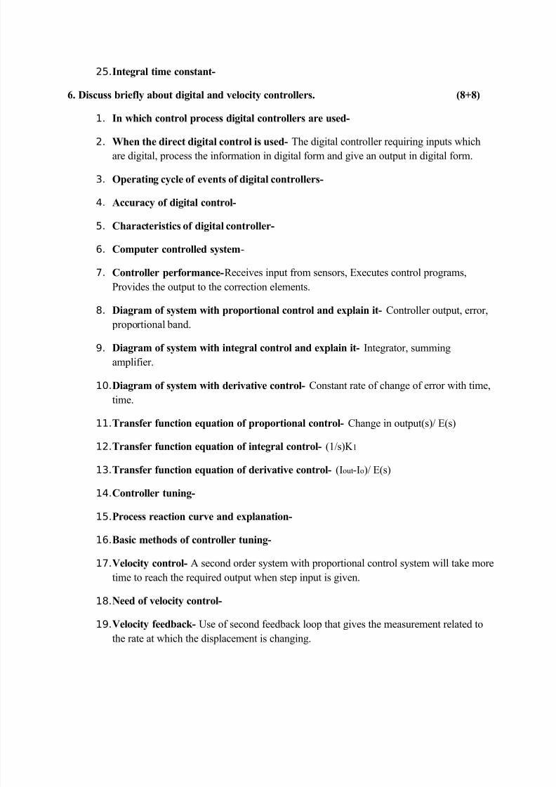
6. Use of AND gate and its diagram- Is a basic digital logic gate that implements
logical conjunction.
7. Standard symbol of AND gate and its truth table-
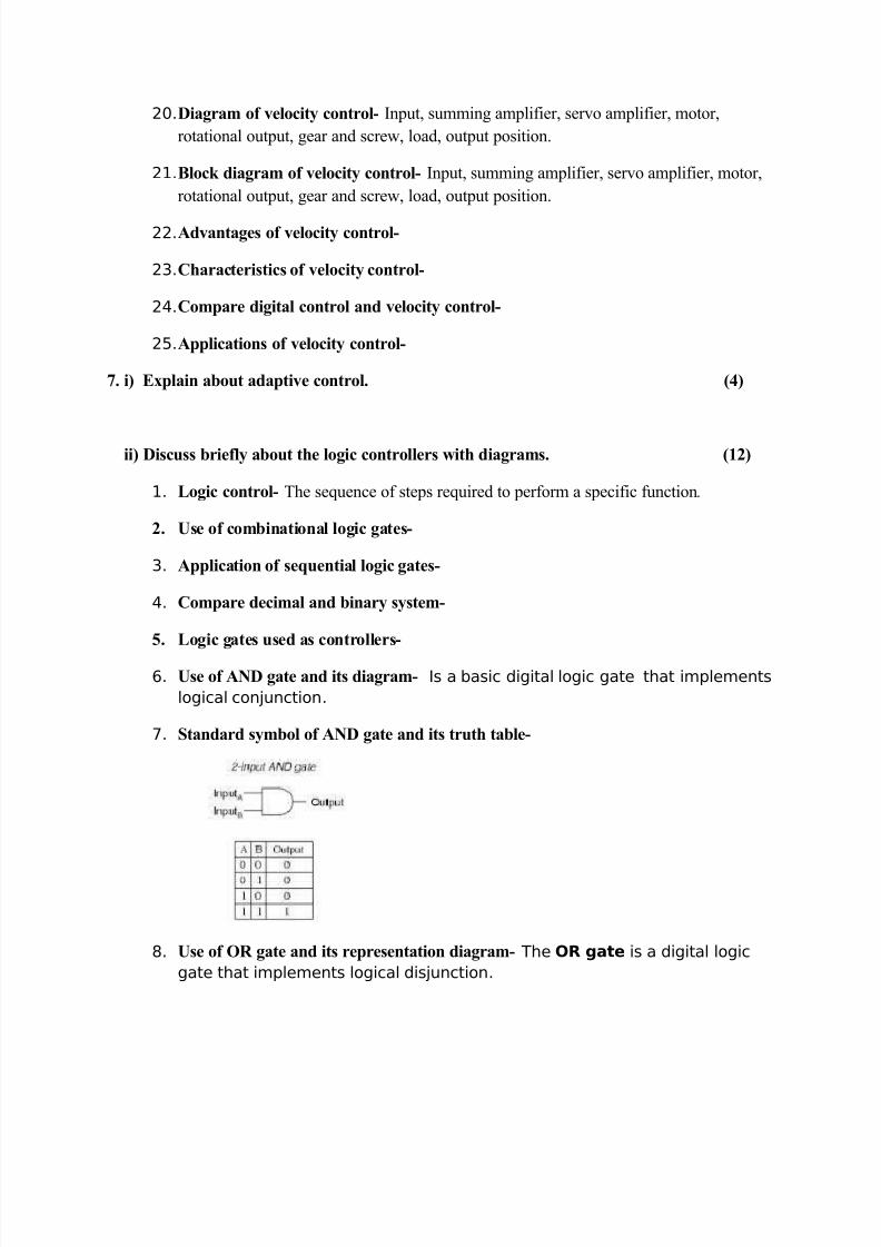
8. Use of OR gate and its representation diagram- The OR gate is a digital logic
gate that implements logical disjunction.
7/31/2019 MECH-3 - 16(1)(1)
http://slidepdf.com/reader/full/mech-3-1611 9/12
9. Symbol of OR gate and its truth table-
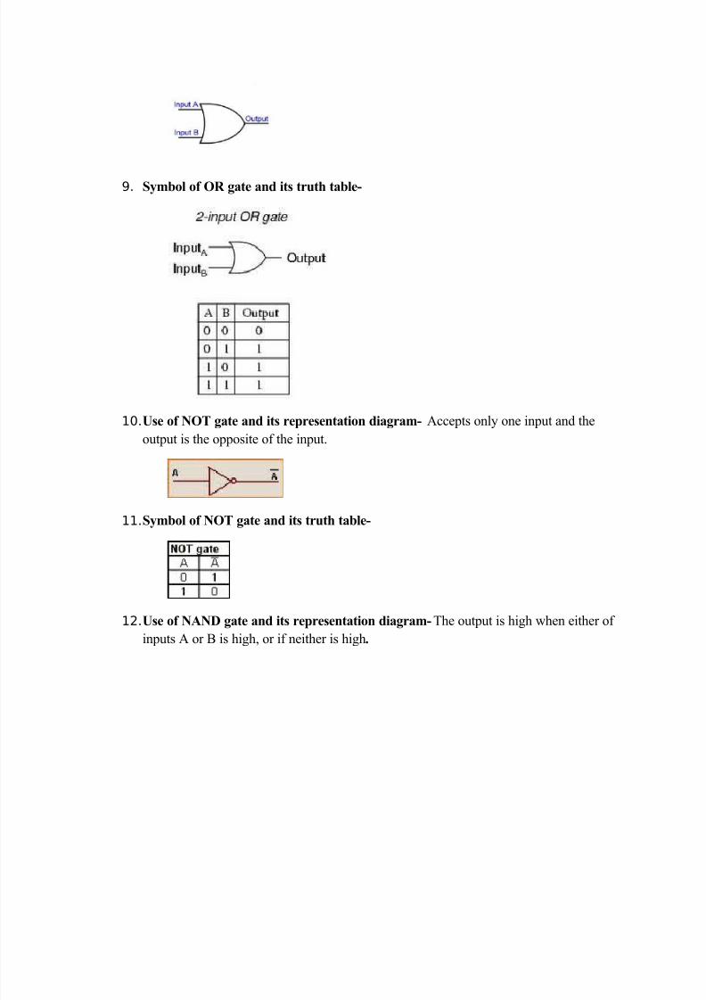
10.Use of NOT gate and its representation diagram- Accepts only one input and the
output is the opposite of the input.
11.Symbol of NOT gate and its truth table-
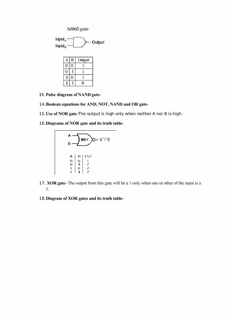
12.Use of NAND gate and its representation diagram-The output is high when either of
inputs A or B is high, or if neither is high.
7/31/2019 MECH-3 - 16(1)(1)
http://slidepdf.com/reader/full/mech-3-1611 10/12
13. Pulse diagram of NAND gate-
14.Boolean equations for AND, NOT, NAND and OR gate-
15.Use of NOR gate- The output is high only when neither A nor B is high.
16.Diagrams of NOR gate and its truth table-
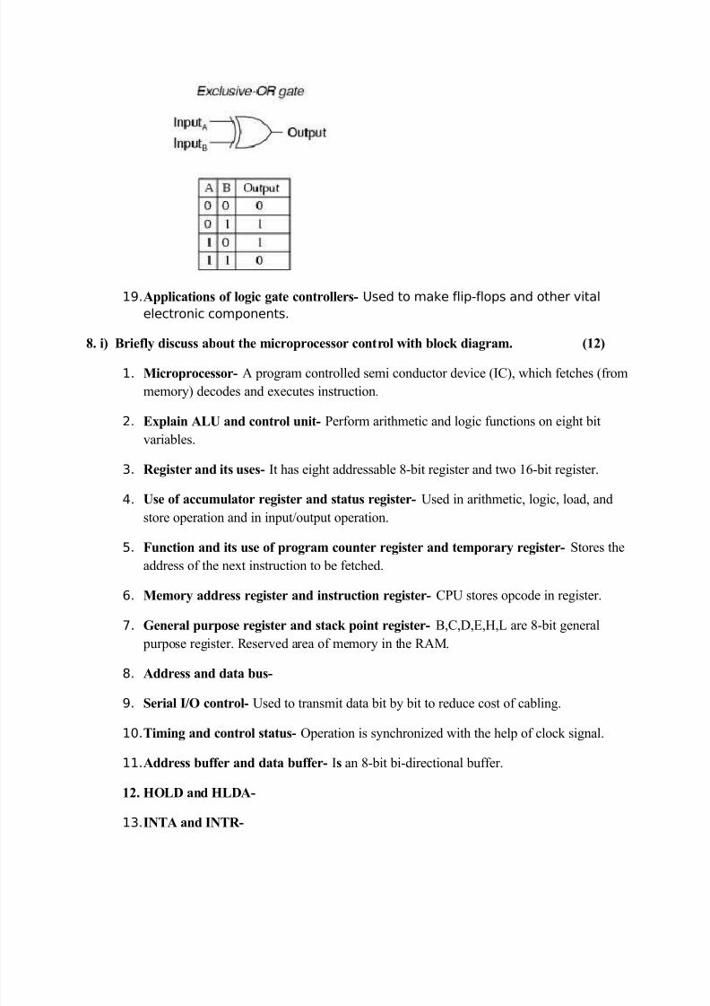
17. XOR gate- The output from this gate will be a 1 only when one or other of the input is a
1.
18.Diagram of XOR gates and its truth table-
7/31/2019 MECH-3 - 16(1)(1)
http://slidepdf.com/reader/full/mech-3-1611 11/12
19.Applications of logic gate controllers- Used to make flip-flops and other vital
electronic components.
8. i) Briefly discuss about the microprocessor control with block diagram. (12)
1. Microprocessor- A program controlled semi conductor device (IC), which fetches (from
memory) decodes and executes instruction.
2. Explain ALU and control unit- Perform arithmetic and logic functions on eight bit
variables.
3. Register and its uses- It has eight addressable 8-bit register and two 16-bit register.
4. Use of accumulator register and status register- Used in arithmetic, logic, load, and
store operation and in input/output operation.
5. Function and its use of program counter register and temporary register- Stores the
address of the next instruction to be fetched.
6. Memory address register and instruction register- CPU stores opcode in register.
7. General purpose register and stack point register- B,C,D,E,H,L are 8-bit general
purpose register. Reserved area of memory in the RAM.
8. Address and data bus-
9. Serial I/O control- Used to transmit data bit by bit to reduce cost of cabling.
10.Timing and control status- Operation is synchronized with the help of clock signal.
11.Address buffer and data buffer- Is an 8-bit bi-directional buffer.
12. HOLD and HLDA-
13.INTA and INTR-
7/31/2019 MECH-3 - 16(1)(1)
http://slidepdf.com/reader/full/mech-3-1611 12/12
14.TRAP in interrupt control- Interrupt control has five interrupt input. TRAP is one of
the interrupt input.
15.Use of RESET IN and RESET OUT-
16.ALE and interrupt control- The processor fetches, decodes and execute instruction insequence.
17.ROM, PROM and EPROM-
18.Incrementer and Decrementer- 16-bit register is used to increment or decrement the
program counter or stock pointer as a execution of instruction related to them.
19.SID and SOD- Serial I/O control provides SID and SOD for serial communication.
20.Applications of MP- Greater variety of program become feasible.
ii) Explain about PID controllers. (4)
21.Diagram of controlled output with time of PID control- Resister, capacitor.
22.Advantage of PID control- Considering this as a proportional controller which has
integral control to eliminate the offset error and derivative control to reduce time lags.
23.Three mode controllers- Combining all three modes of control enable a controller to be
produced which has no offset error and reduce tendency for oscillation.
24.Equation of transfer function of PID controller- Transfer function= K Pe+(1/s)
(K 1)E(s)+sK D(s)
25.Diagram of error signal of PID controller and explain-