
MARINE ENGINE EXHAUST GAS EMISSION AFTERTREATMENT...
9
Journal of KONES Powertrain and Transport, Vol. 18, No. 4 2011 MARINE ENGINE EXHAUST GAS EMISSION AFTERTREATMENT SYSTEM CONCEPT Jarosáaw MyĞków, Tadeusz Borkowski Maritime University of Szczecin Waáy Chrobrego Street 1/2, 70-500 Szczecin, Poland tel.: +48 91 4809400, fax: +48 91 4809575 e-mail: [email protected], [email protected] Mark Bludszuweit, Werner Fröhlingsdorf Motoren – und Energietechnik GmbH Erich-Schlesinger-Street 50, 18059 Rostock, Germany e-mail: [email protected] Abstract In 2008 the International Maritime Organization - IMO decided to strengthen the requirements for new ships from 2011 - Tier II. However, for Emission Control Areas (ECAs), such as the Baltic Sea, stringent rules will apply from 1 January 2016 for new ships - Tier III. The new standards introduce restrictions on exhaust emissions from diesel engines - NO x and SO x . The paper presents proposal of new design an existing exhaust gas system of experimental marine diesel engine, which is situated in the Laboratory of Maritime Academy in Szczecin. The conception is due to meet to new environmental regulations. Arrangements of exhaust line, CFD model of the SCR reference plant, CFD model - inlet and outlet boundary conditions, pressure loss model for the catalytic elements, simulation results – streamlines, velocity distribution, reaction progress distribution ate presented in the paper as well design description of system of laboratory– 4-stroke and turbocharged engine. . The means of the reduction systems are based on conventional marine exhaust gas installation that includes noise silencer and soot-catcher. The after-treatment methods do not introduce significant changes in engine arrangement and operation. A new gas purifying system should be installed in the engine exhaust gas system. Keywords: marine diesel engine, exhaust emission, particulate matter, non-thermal plasma reactor 1. Introduction Oceangoing vessels are a major source of air pollution in sea environment. Ships emissions affect the shore side area – especially ports vicinity [6]. Emissions of nitrogen oxides - NO x from shipping represent about 8-12% of global anthropogenic NO x emissions and around 40% of global NO x emissions from transport of freight mean [6]. The shipping signifies approximately 15% of global freight transport CO 2 emissions (2 to 3% of total global CO 2 emissions) [1-4]. In 2008 International Maritime Organization decided to strengthen the requirements for new ships from 2011 and pronounced the Tier II. However, for Emission Control Areas (ECAs), such as the Baltic Sea, very stringent rules will apply from 1 January 2016 for new-built ships - Tier III. It will establish the NO x emission reduction by 80% from current limit values - Tier I that took effect from 1 st of January 2000. IMO limits – Tier I, II and III shows Fig. 1. A variety of flue gas treatment methods have been developed to remove NO x and other harmful components from the exhaust gas. There are numerous methods of emission suppression and they can be divided into three main groups: - preliminary fuel and air treatment, - construction changes of combustion chamber, fuel injection shaping, etc.
Transcript of MARINE ENGINE EXHAUST GAS EMISSION AFTERTREATMENT...
Journal of KONES Powertrain and Transport, Vol. 18, No. 4 2011
MARINE ENGINE EXHAUST GAS EMISSION AFTERTREATMENT SYSTEM CONCEPT
Jaros aw My ków, Tadeusz Borkowski
Maritime University of Szczecin
Wa y Chrobrego Street 1/2, 70-500 Szczecin, Poland tel.: +48 91 4809400, fax: +48 91 4809575
e-mail: [email protected], [email protected]
Mark Bludszuweit, Werner Fröhlingsdorf
Motoren – und Energietechnik GmbH Erich-Schlesinger-Street 50, 18059 Rostock, Germany
e-mail: [email protected]
Abstract
In 2008 the International Maritime Organization - IMO decided to strengthen the requirements for new ships from 2011 - Tier II. However, for Emission Control Areas (ECAs), such as the Baltic Sea, stringent rules will apply from 1 January 2016 for new ships - Tier III. The new standards introduce restrictions on exhaust emissions from diesel engines - NOx and SOx. The paper presents proposal of new design an existing exhaust gas system of experimental marine diesel engine, which is situated in the Laboratory of Maritime Academy in Szczecin. The conception is due to meet to new environmental regulations. Arrangements of exhaust line, CFD model of the SCR reference plant, CFD model - inlet and outlet boundary conditions, pressure loss model for the catalytic elements, simulation results – streamlines, velocity distribution, reaction progress distribution ate presented in the paper as well design description of system of laboratory– 4-stroke and turbocharged engine. . The means of the reduction systems are based on conventional marine exhaust gas installation that includes noise silencer and soot-catcher. The after-treatment methods do not introduce significant changes in engine arrangement and operation. A new gas purifying system should be installed in the engine exhaust gas system.
Keywords: marine diesel engine, exhaust emission, particulate matter, non-thermal plasma reactor 1. Introduction
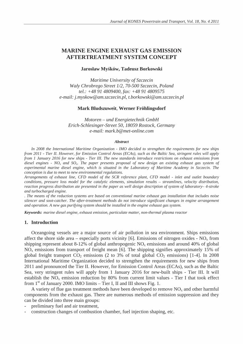
Oceangoing vessels are a major source of air pollution in sea environment. Ships emissions affect the shore side area – especially ports vicinity [6]. Emissions of nitrogen oxides - NOx from shipping represent about 8-12% of global anthropogenic NOx emissions and around 40% of global NOx emissions from transport of freight mean [6]. The shipping signifies approximately 15% of global freight transport CO2 emissions (2 to 3% of total global CO2 emissions) [1-4]. In 2008 International Maritime Organization decided to strengthen the requirements for new ships from 2011 and pronounced the Tier II. However, for Emission Control Areas (ECAs), such as the Baltic Sea, very stringent rules will apply from 1 January 2016 for new-built ships - Tier III. It will establish the NOx emission reduction by 80% from current limit values - Tier I that took effect from 1st of January 2000. IMO limits – Tier I, II and III shows Fig. 1.
A variety of flue gas treatment methods have been developed to remove NOx and other harmful components from the exhaust gas. There are numerous methods of emission suppression and they can be divided into three main groups: - preliminary fuel and air treatment, - construction changes of combustion chamber, fuel injection shaping, etc.
J. My ków, T. Borkowski, M. Bludszuweit, W. Fröhlingsdorf
- exhaust gas after-treatment. Preliminary fuel and air treatment methods are related to water adding. In case of fuel
treatment water could be added by a dedicated homogenizer, where the fuel is mixed with fresh water. Maximum water concentration is 20%. Performance of this solution – reducing of emission reaches 40%.
Fig. 1. Annex VI of Marpol 73/78 Convention – the IMO NOx emission limits Tier I, II and III
Fresh water can also be used to form steam mixtures with air. The humid air motor – HAM,
brings hot water in contact with the compressed inlet air, in a humidification tower. Water evaporates thereby increasing air humidity to saturation state and decreasing charge air temperature. This technique can attribute reduction NOx emission up to 50%.
Engine process modifications involves changes an engine combustion process in order to reduce NOx emissions. These modifications include: exhaust gas recirculation (EGR); addition of water or urea to combustion and electronic control [7]. EGR can achieve 50% reductions in NOx but can increase CO and PM emissions [7]. Engine control involves in-engine variables optimization (combustion time, compression ratio, valve timing) to increase fuel economy and decrease emissions; this combined approach significantly could reduce NOx up to 35% [7].
After-treatment technologies control the emissions in exhaust gases. AT-T devices used to reduce NOx and includes: Plasma Based Catalytic Treatment – PBCT, Selective Catalytic Reduction – SCR, Selective Non-Catalytic Reduction – SNCR, Lean NOx Trap – LNT, Diesel Oxidation Catalysts – DOC, and NOx Absorber Catalyst. However, technology gives some limitations. A number of emission control techniques, including oxidation reactors, SCR, and NOx Absorber Catalysts perform most effectively with low sulphur fuel oil.
Techniques mentioned above are particularly dedicated to cruise mode of ship operation, when the main engine is running. When ships stay in ports the other devices like diesel generators and boilers are responsible for the emission. Basically, diesel generators on-board the vessel are used to produce the electricity for hoteling, cargo handling, and ballast pumping. Oil fired boilers are used to heat up fuel oil or cargo oil, steam production for auxiliary steam-driven cargo pumps. Three elementary measures were implemented to reduce emissions at berth: - Fuel switching – currently, involving low sulphur fuel while at berth to reduce SOx and PM
emissions. In the future auxiliary generators are expected to be supplied by LNG at berth to intensive emission reduction: NOx, SOx and PM.
- Shore electricity supply – alternative ships’ electric source. Ship electricity is supplied from the land based electric grid. It can partly remove the exhaust emission from port space.
- Cleaner exhaust gas, after-treatment methods. From numerous methods, after-treatment technology seems to be one of the most promising
methods. It could be applied to all devices onboard: main and auxiliary engines and boilers. This
308
Marine Engine Exhaust Gas Emission Aftertreatment System Concept
technique does not introduce any significant changes in the engine structure – only cleaning devices are located on the exhaust pipeline.
2. After-treatment technology – PBCT and SCR systems
A novel technique for cleaning the exhaust gases is non-thermal plasma – NTP reactor and in presence of catalyst. Roughly, non-thermal plasma represents gas that has been ionised into a mixture of highly reactive molecules. Plasma is created by means of high-voltage discharges. The generated electric field produces free electrons, which travel through the gas creating O and OH radicals and they are effective in oxidising exhaust gas emission compounds, thereby reducing soot-emissions. NO is oxidised to NO2 by the oxygen-radicals. Currently, non-thermal plasma application is found in exhaust gas purification system to remove NOx and PM. Non-thermal plasma created by high-voltage discharges is effective in oxidising exhaust gas components, and soot reducing. Non-thermal plasma assembly can be combined with a diesel particulate filter. In this application it is exclusively used to start the regeneration of the particulate filter [5]. Combination NTP reactor and catalyst can also be implemented as a standalone after-treatment method.
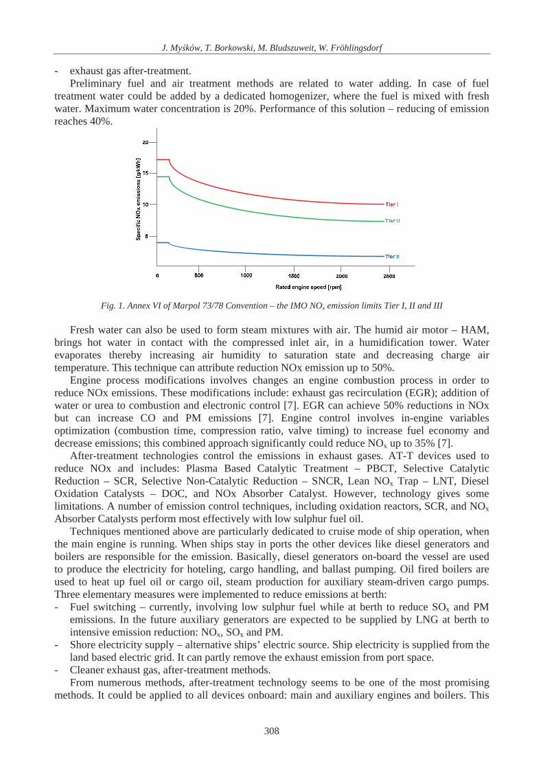
The SCR technology has become the most promising abatement technique. Selective Catalytic Reduction of NOx with ammonia (SCR-NH3) injection is currently employed as a basic NOx removal technology in stationary power plants application. The SCR system reduces the emissions of nitrogen oxides by up to 95% and requires rather low-sulphur bunker oil and an exhaust gas temperature above 300°C. Efficiently, NO and NO2 are reduced to N2 and H2O by mixing water solution of urea into the exhaust gas before it passes through a catalytic converter. This reaction takes place in a satisfactory manner only within a certain temperature range 300-400°C. The average exhaust gas temperature of medium speed four-stroke engines can be found within this range. However, in case of large bore, slow speed and two-stroke diesel engines only a certain effective power range can deliver required process conditions. In the latter case, the catalytic converter must be placed between the engine exhaust gas receiver and the turbocharger, where the temperature is enough high. Fig. 2 shows the conventional SCR system, which can be implemented to 4-stroke, medium speed engines.
Both solutions PBCT and SCR were accepted to introduce in laboratory exhaust system as equally effective technologies.
Fig. 2. SCR principle diagram 3. System of laboratory engine – design description
Laboratory engine is 4-stroke and turbocharged. The silencer – type TLP 250 is situated in the exhaust line and then gas outlets to atmosphere by funnel. The silencer has two designations: the
309

J. My ków, T. Borkowski, M. Bludszuweit, W. Fröhlingsdorf
first one is the silencer and second one is a soot-catcher. Exhaust duct consists of two steel pipes connected by elbows.
Engine specification data (see Tab. 1), which is placed in laboratory is shown below.
Tab.1 Engine specification data
Engine Designation Nominal performance
Sulzer 6AL20/24 Generator set or main propulsion Pnom=324 [kW] nnom=720 [rpm]
The duct contains two compensators – one on the engine side (outlet from the turbocharger)
and another one close to silencer. The diameter of the pipe is 275 [mm] and its length 3000 [mm]. Arrangements of the exhaust lines are shown on the Fig. 3.
Fig. 3. Arrangements of exhaust line
Silencer specifications data is shown in Tab. 2.
Tab. 2. Silencer specification data
Silencer type Noise damp Pressure drop Weight
TLP-250 20 [dB] 443 [Pa] 488 [kg]
Due to the location of the laboratory in the city centre, it was decided to do test in terms of
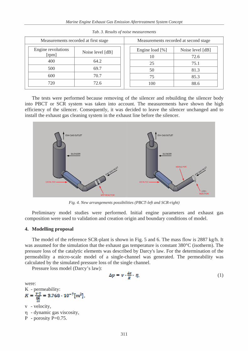
efficiency of the silencer to reduce noise. The test was carried out in December 2010. Noise measurements were done simultaneously in two points according to PN-W-1350-2 rule by the noise analyser SVAN 945 and SVAN 958 the noise level measurement instrument. Test was divided on the two stages. On the first stage engine was on idle load and the speed of the engine was changed into 400, 500, 600 and 720 [rpm]. Second stage was done during steady engine revolutions – 720 [rpm] and engine load was changed in 10, 25, 50, 75 and 100% of the nominal engine load – the Tab. 3 shows results of the measurements.
310
Marine Engine Exhaust Gas Emission Aftertreatment System Concept
Tab. 3. Results of noise measurements
Measurements recorded at first stage Measurements recorded at second stage
Engine revolutions [rpm] Noise level [dB]
400 64.2 500 69.7 600 70.7 720 72.6
Engine load [%] Noise level [dB] 10 72.6 25 75.1 50 81.3 75 85.3
100 88.6
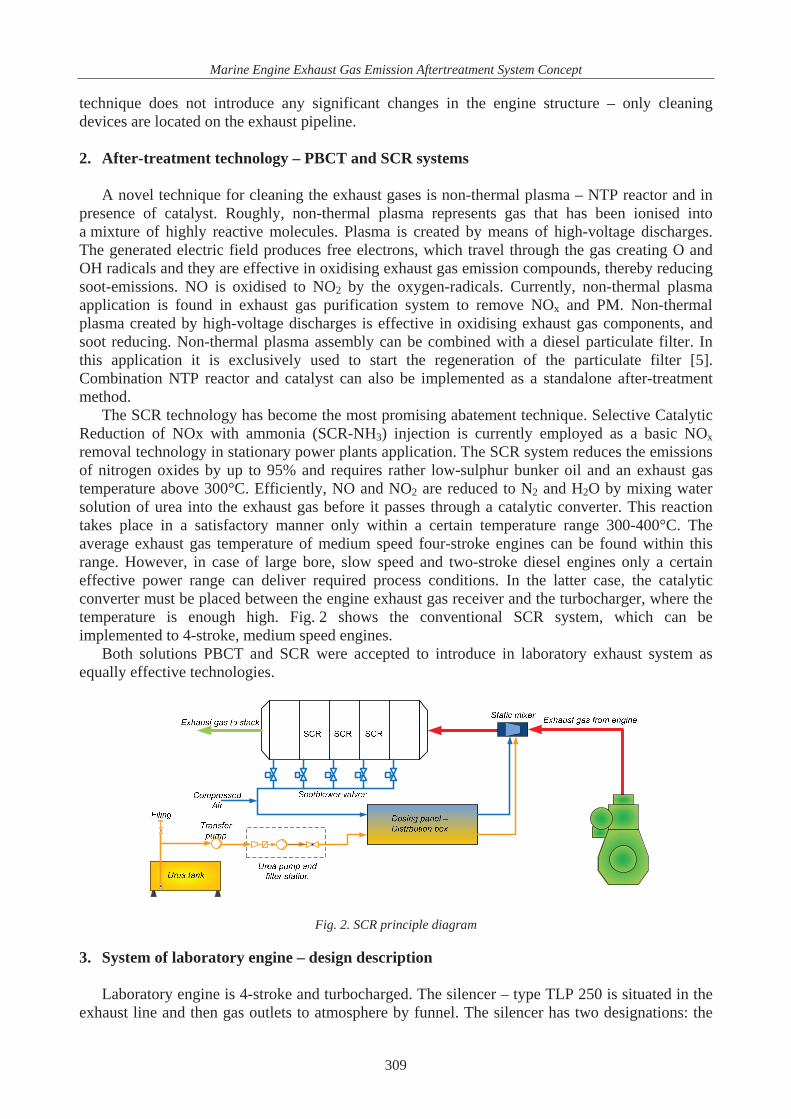
The tests were performed because removing of the silencer and rebuilding the silencer body into PBCT or SCR system was taken into account. The measurements have shown the high efficiency of the silencer. Consequently, it was decided to leave the silencer unchanged and to install the exhaust gas cleaning system in the exhaust line before the silencer.
Fig. 4. New arrangements possibilities (PBCT-left and SCR-right)
Preliminary model studies were performed. Initial engine parameters and exhaust gas
composition were used to validation and creation origin and boundary conditions of model. 4. Modelling proposal
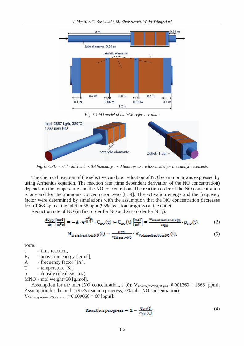
The model of the reference SCR-plant is shown in Fig. 5 and 6. The mass flow is 2887 kg/h. It was assumed for the simulation that the exhaust gas temperature is constant 380°C (isotherm). The pressure loss of the catalytic elements was described by Darcy's law. For the determination of the permeability a micro-scale model of a single-channel was generated. The permeability was calculated by the simulated pressure loss of the single channel.
Pressure loss model (Darcy’s law): , (1)
were: K - permeability:
,
v - velocity, - dynamic gas viscosity,
P - porosity P=0.75.
311
J. My ków, T. Borkowski, M. Bludszuweit, W. Fröhlingsdorf
Fig. 5 CFD model of the SCR reference plant
Fig. 6. CFD model - inlet and outlet boundary conditions, pressure loss model for the catalytic elements
The chemical reaction of the selective catalytic reduction of NO by ammonia was expressed by
using Arrhenius equation. The reaction rate (time dependent derivation of the NO concentration) depends on the temperature and the NO concentration. The reaction order of the NO concentration is one and for the ammonia concentration zero [8, 9]. The activation energy and the frequency factor were determined by simulations with the assumption that the NO concentration decreases from 1363 ppm at the inlet to 68 ppm (95% reaction progress) at the outlet.
Reduction rate of NO (in first order for NO and zero order for NH3):
, (2)
, (3)
were: t - time reaction, Ea - activation energy [J/mol], A - frequency factor [1/s], T - temperature [K], - density (ideal gas law),
MNO - mol weight=30 [g/mol]. Assumption for the inlet (NO concentration, t=t0): VVolumefraction,NO(t0)=0.001363 = 1363 [ppm];
Assumption for the outlet (95% reaction progress, 5% inlet NO concentration): VVolumefraction,NO(treac,end)=0.000068 = 68 [ppm]:
, (4)
312
Marine Engine Exhaust Gas Emission Aftertreatment System Concept
The necessary expressions of the reaction model and the pressure loss were integrated in the CFD model. The structured mesh obtain 187600 hexahedra elements (mesh generator: Altair Hypermesh). By the steady state analysis with Ansys CFX a physical time step of 0.01s was used. 5. Simulation results
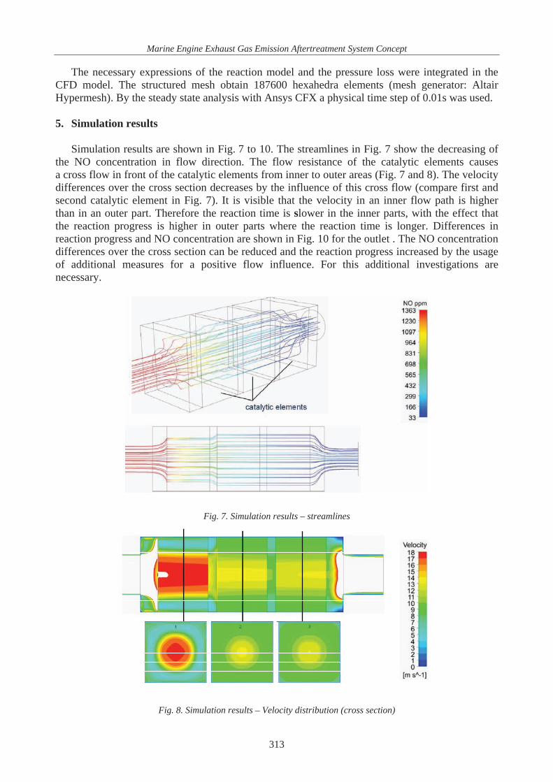
Simulation results are shown in Fig. 7 to 10. The streamlines in Fig. 7 show the decreasing of the NO concentration in flow direction. The flow resistance of the catalytic elements causes a cross flow in front of the catalytic elements from inner to outer areas (Fig. 7 and 8). The velocity differences over the cross section decreases by the influence of this cross flow (compare first and second catalytic element in Fig. 7). It is visible that the velocity in an inner flow path is higher than in an outer part. Therefore the reaction time is slower in the inner parts, with the effect that the reaction progress is higher in outer parts where the reaction time is longer. Differences in reaction progress and NO concentration are shown in Fig. 10 for the outlet . The NO concentration differences over the cross section can be reduced and the reaction progress increased by the usage of additional measures for a positive flow influence. For this additional investigations are necessary.
Fig. 7. Simulation results – streamlines
Fig. 8. Simulation results – Velocity distribution (cross section)
313

J. My ków, T. Borkowski, M. Bludszuweit, W. Fröhlingsdorf
Fig. 9. NO ppm distribution
Fig. 10 and 11. Simulation results – Reaction progress distribution
6. Conclusions
The performed investigations show an opportunity to model and simulate the flow and reaction process in a real SCR catalytic reactor. The parameters of the pressure loss and reaction kinetic models can be further improved by additional experimental results. The application to other reactor geometries or boundary conditions is possible. It is also feasible to integrate a thermal analysis in the simulation process. Heating up and cooling down processes of catalytic elements can also be treated. As mentioned above the efficiency of a catalytic reactor can be improved by the usage of additional measures for a further homogenisation of the flow field.
The considered means of the reduction systems are based on conventional marine exhaust gas installation that includes noise silencer and soot-catcher. New, additional functional cleaning system components: non-thermal plasma reactor, catalytic module will be installed in-line with existed arrangement. However, an alternative abatement system retrofitting would be available i.e. SCR (selective catalytic system).
The after-treatment methods do not introduce significant changes in engine arrangement and operation, but deal only with exhaust gases. A new gas purifying system should be installed in the engine exhaust gas system.
314
Marine Engine Exhaust Gas Emission Aftertreatment System Concept
References [1] Buhaug, Ø. et al., Second IMO GHG Study 2009, International Maritime Organization (IMO)
London, UK 2009. [2] Corbett, J. J. et al., Mortality from Ship Emissions: A Global Assessment 41(24),
Environmental Science and Technology 8512, 2007. [3] Dalsøren, S. B. et al., Update on Emissions and Environmental Impacts from the International
Fleet of Ships, The Contribution from Major Ship Types and Ports 9 Atmospheric Chemistry and Physics, 2171, 2009.
[4] Eyring, V. et al., Emissions from International Shipping: 1. The Last 50 years, Journal of Geophysical Research, 110, 2005.
[5] McAdams, R., Beech, P., Gillespie, R., Guy, C., Jones, S., Liddell, T., Morgan, R., Shawcross, J., Weeks, D., Hughes, D., Oesterle, J., Non-thermal plasma based technologies for the aftertreatment of automotive exhaust particulates and marine diesel exhaust NOx, DEER, Newport, Rhode Island 2003.
[6] Moldanováa, J. et al., Characterisation of Particulate Matter and Gaseous Emissions from a Large Ship Diesel Engine, 43 Atmospheric Environment, 2632, 2009.
[7] Rahai, H. R., Hefazi, H., Emission Control Technologies for Oceangoing Vessels (OGVs), California Air Resources Board: Sacramento, CA 2008.
[8] Wu, B., Xiao, P., Liu, X., Performance and Kinetics Studies on Selective Catalytic Reduction of NOx with NH3 over MnOx-WO3 / TiO2 Catalyst, Chem. Res. Chinese Universities, 26(6), pp. 1002-1006, 2010.
[9] Jeon, S. M., Jung, S. H., Yoo, K. S., Kim, S. D., Selective Catalytic Reduction of NO by NH3 over a Bulk Sulfated CuO/ -Al2O3 Catalyst, Ind. Eng. Chem. Res., 38, pp. 2210-2215, 1999.
315