L im ited A rm -R otation S h ift-T rellis (L A R S ) an d ...LARS' end-post assemblies (Fig. 4, 7)...
33
i ___________________________________________________________________________________________ Virginia Agricultural Experiment Station Bulletin 99-1 ___________________________________________________________________________________________ Limited Arm-Rotation Shift-Trellis (LARS) and Primocane Management Apparatus (PMA) for Raspberries and Blackberries (Rubus cvs. or crops) Herbert D. Stiles Virginia Tech Southern Piedmont Agricultural Research and Extension Center Blackstone March 1999 This publication available at: http://www.vaes.vt.edu/research/publications/
Transcript of L im ited A rm -R otation S h ift-T rellis (L A R S ) an d ...LARS' end-post assemblies (Fig. 4, 7)...
i
______________________________________________________________________________________________________________________________________________________________________________________
VViirrggiinniiaa AAggrriiccuullttuurraall EExxppeerriimmeenntt SSttaattiioonn BBuulllleettiinn 9999--11______________________________________________________________________________________________________________________________________________________________________________________
LLiimmiitteedd AArrmm--RRoottaattiioonn SShhiifftt--TTrreelllliiss((LLAARRSS)) aanndd PPrriimmooccaannee MMaannaaggeemmeennttAAppppaarraattuuss ((PPMMAA)) ffoorr RRaassppbbeerrrriieess aannddBBllaacckkbbeerrrriieess ((RRuubbuuss ccvvss.. oorr ccrrooppss))
HHeerrbbeerrtt DD.. SSttiilleess
VViirrggiinniiaa TTeecchhSSoouutthheerrnn PPiieeddmmoonntt AAggrriiccuullttuurraall RReesseeaarrcchh aanndd EExxtteennssiioonn CCeenntteerrBBllaacckkssttoonnee
MMaarrcchh 11999999
TThhiiss ppuubblliiccaattiioonn aavvaaiillaabbllee aatt:: hhttttpp::////wwwwww..vvaaeess..vvtt..eedduu//rreesseeaarrcchh//ppuubblliiccaattiioonnss//
ii
TABLE OF CONTENTS
Page No.TABLE OF CONTENTS................................................................................................................................................. i
List of Diagrams............................................................................................................................................................... ii
List of Tables.................................................................................................................................................................... ii
Acknowledgments............................................................................................................................................................ ii
Introduction...................................................................................................................................................................... 1
Primary differences between LARS and the SSST.......................................................................................................... 4
Straight rows are essential for proper operation of all OSSTS, including LARS........................................................... 5
Sequential procedures for building a limited arm rotation system trellis........................................................................ 5
Additional perspectives and suggestions on LARS installation procedures.................................................................... 7
Rationale of the new primocane management apparatus (PMA).................................................................................... 9
Installation and use of primocane management apparatus.............................................................................................. 9
Literature cited ............................................................................................................................................................... 26
Appendix ........................................................................................................................................................................ 27
COVER PHOTOGRAPH LEGENDS
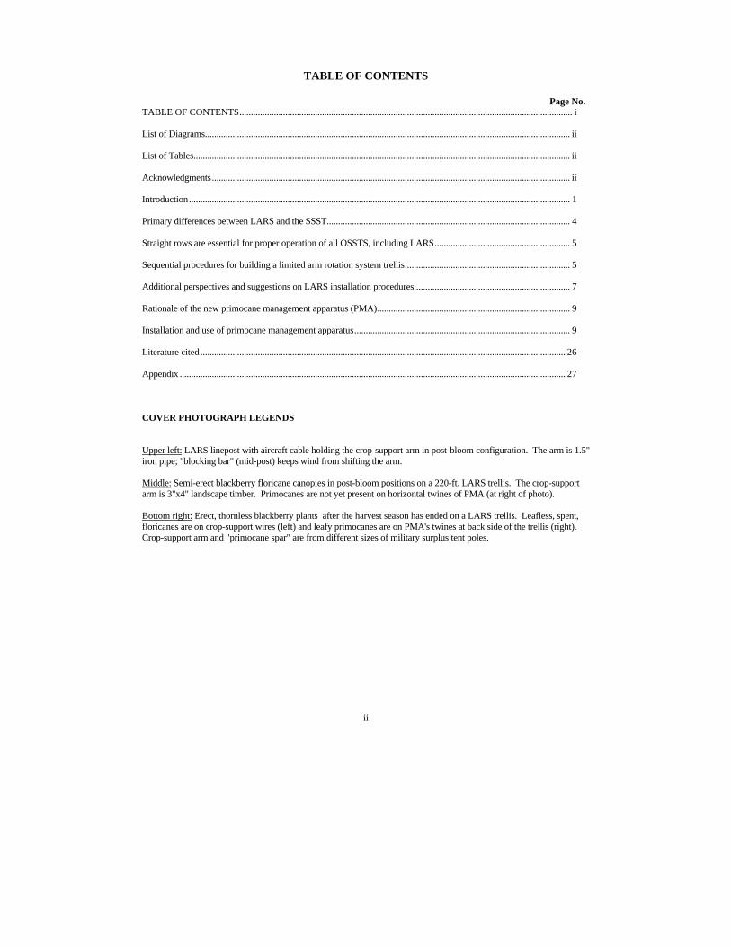
Upper left: LARS linepost with aircraft cable holding the crop-support arm in post-bloom configuration. The arm is 1.5"iron pipe; "blocking bar" (mid-post) keeps wind from shifting the arm.
Middle: Semi-erect blackberry floricane canopies in post-bloom positions on a 220-ft. LARS trellis. The crop-supportarm is 3"x4" landscape timber. Primocanes are not yet present on horizontal twines of PMA (at right of photo).
Bottom right: Erect, thornless blackberry plants after the harvest season has ended on a LARS trellis. Leafless, spent,floricanes are on crop-support wires (left) and leafy primocanes are on PMA's twines at back side of the trellis (right).Crop-support arm and "primocane spar" are from different sizes of military surplus tent poles.
iii
LIST OF TRELLIS DIAGRAMS AND TABLES
Fig. No. Page No.
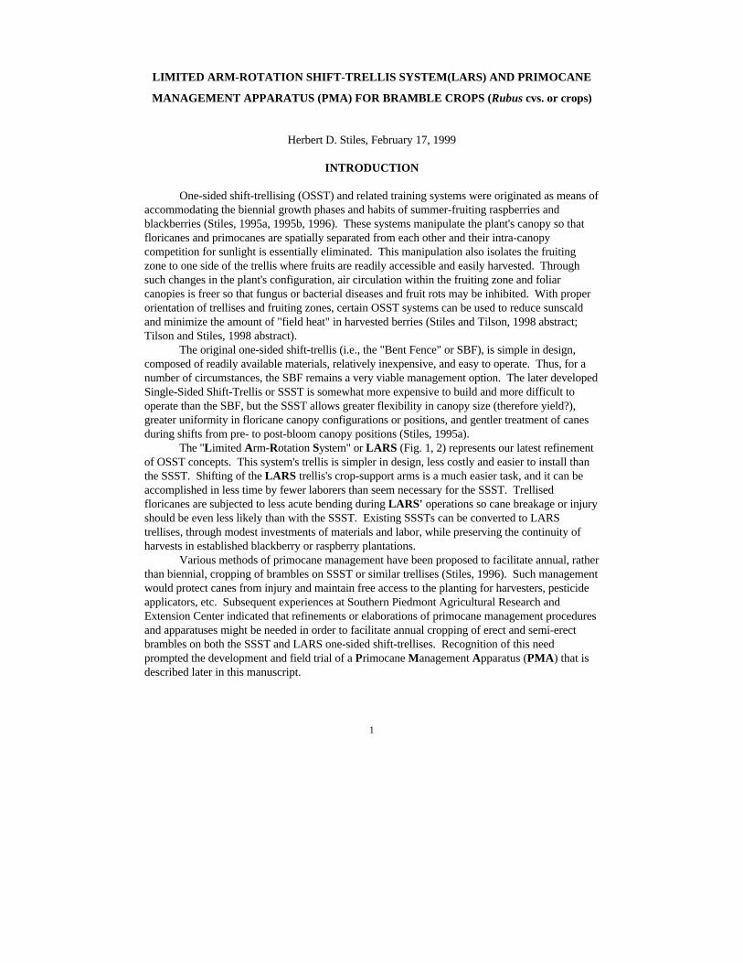
1 LARS, A Shift-Trellis and Training System for Brambles, conceptual diagrams............................................3
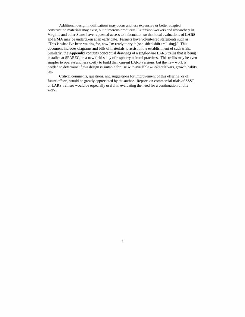
2 Limited Arm Rotation System (LARS) Trellis .................................................................................................3shown without primocane support apparatus
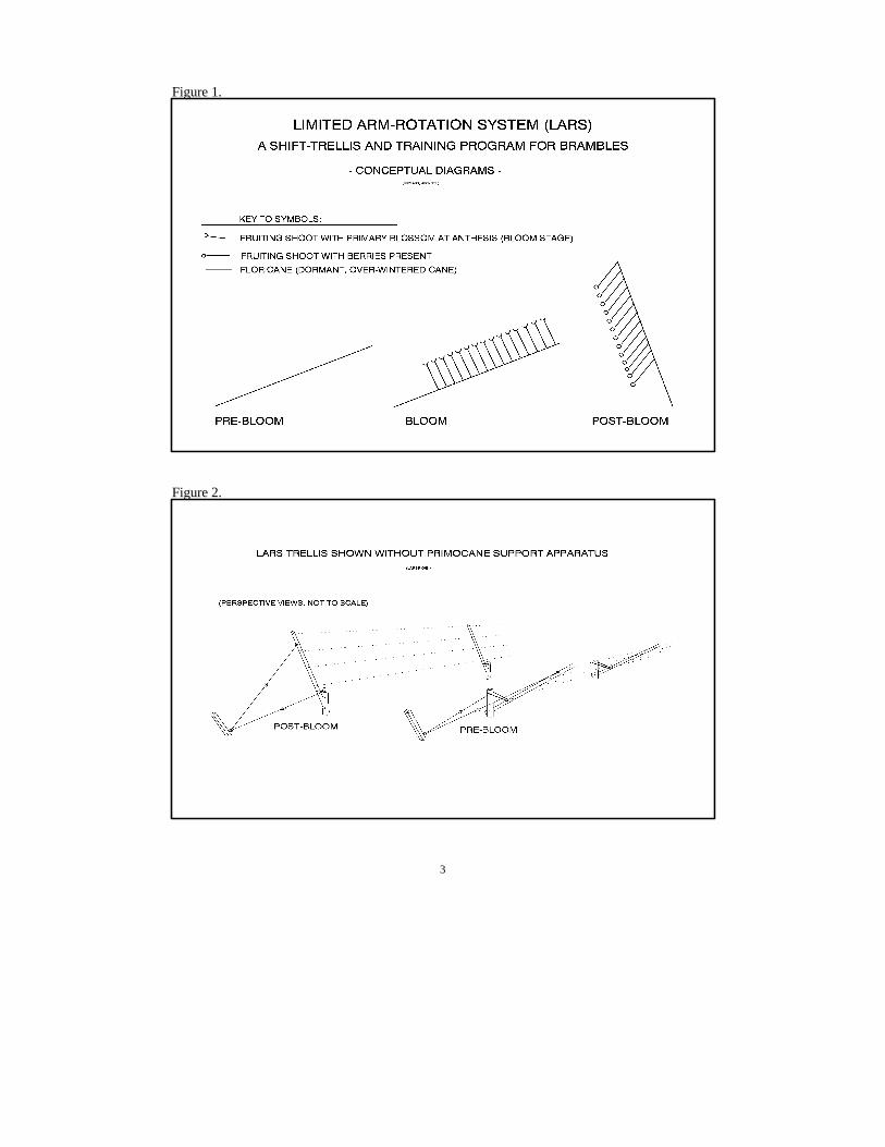
3 Pre- and Post-Bloom Positions of LAR's Crop-Arm Support Cable .................................................................4
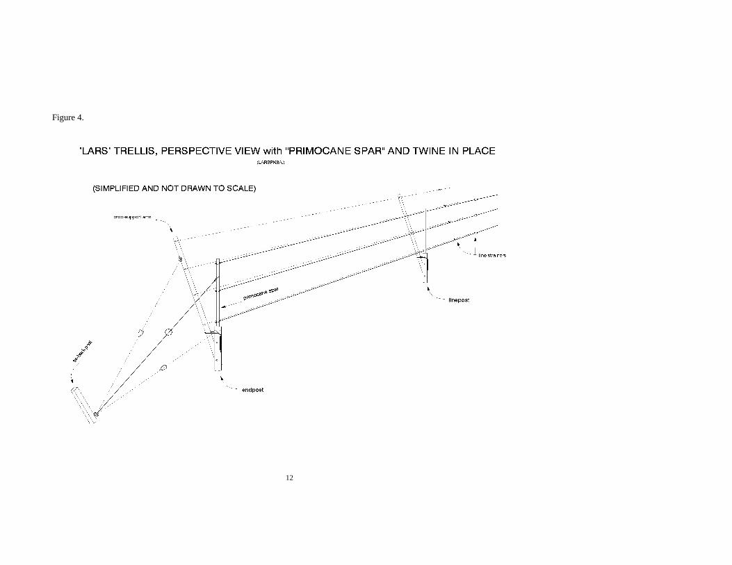
4 Limited Arm Rotation System Trellis with .......................................................................................................12"primocane spar" and twine in place - perspective view
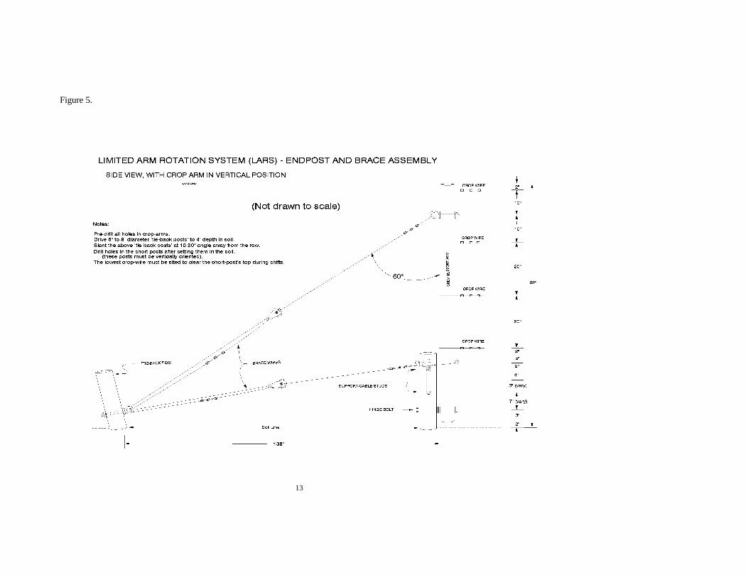
5 Limited Arm Rotation System (LARS) End-Post and Brace Assembly, ..........................................................13side view, with crop arm in vertical position
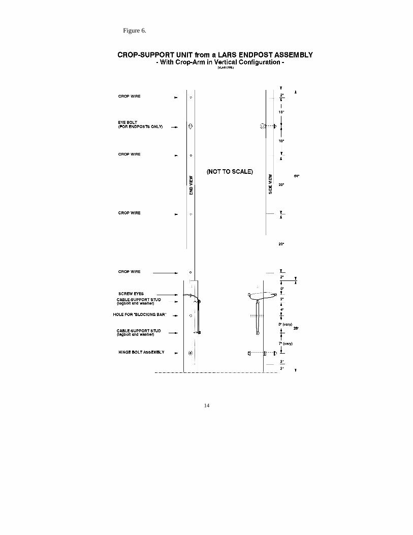
6 Crop-Support Unit from a LARS End-Post Assembly ......................................................................................14with crop-arm in vertical configuration
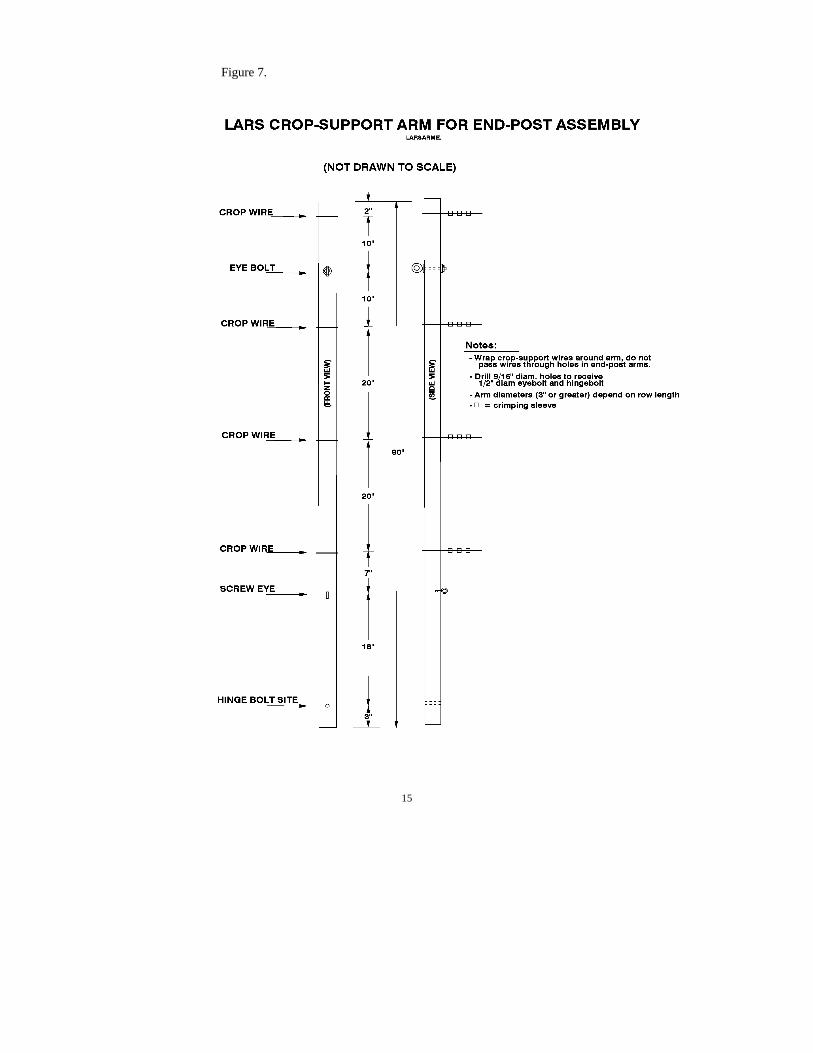
7 LARS Crop-Support Arm for End-Post Assembly............................................................................................15
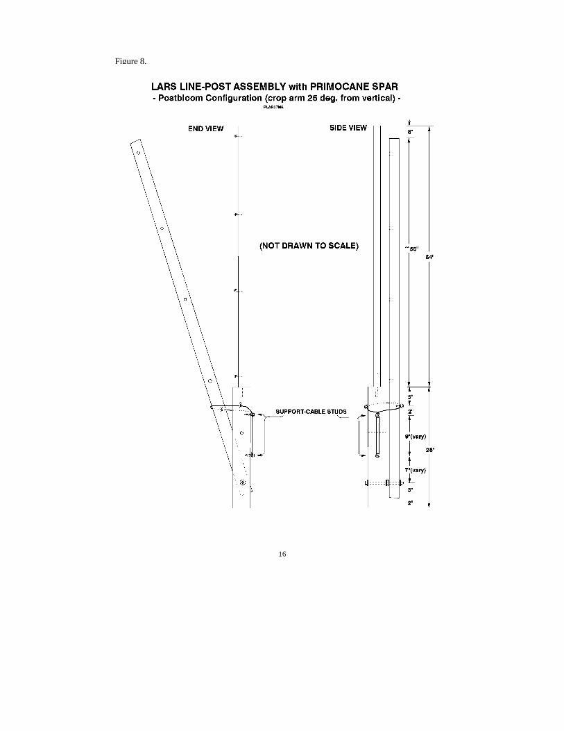
8 LARS Line-Post Assembly with Primocane Spar .............................................................................................16postbloom configuration (crop arm 25 deg. from vertical)
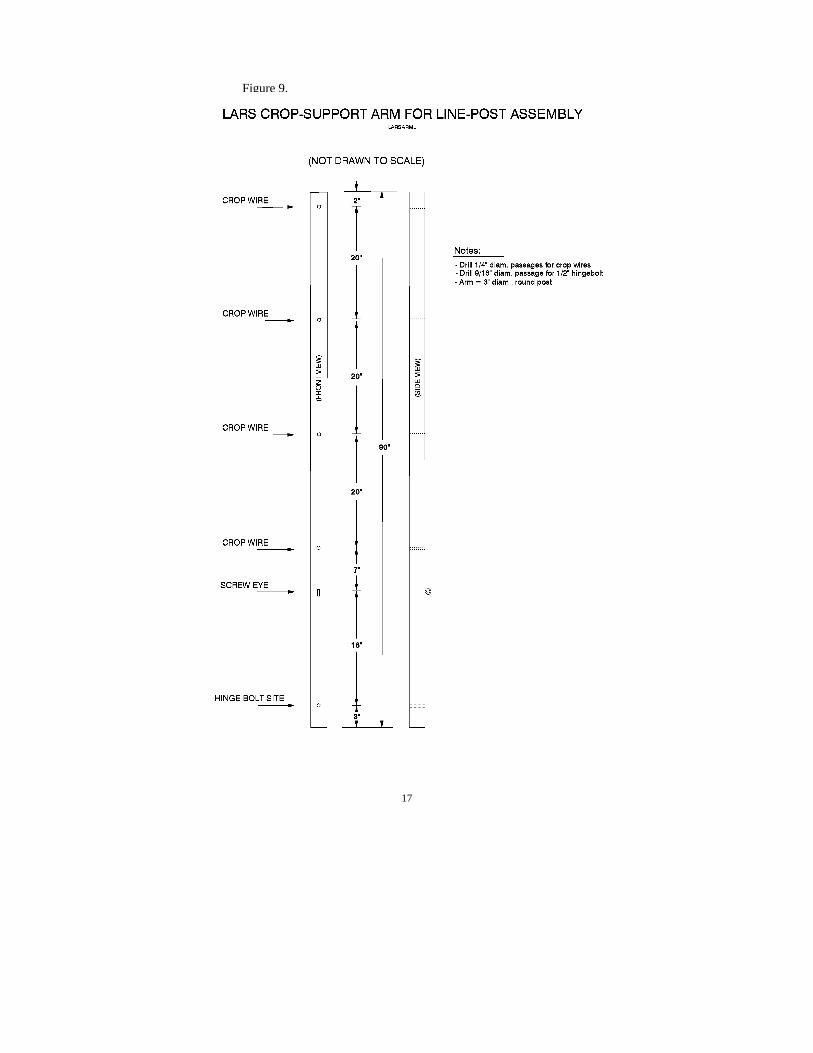
9 LARS Crop-Support Arm for Line-Post Assembly...........................................................................................17
10 Primocane Training-Spar for LARS Trellis ......................................................................................................18
Tables
1 LARS Trellis - Materials for 1 End-Post Assembly in 210' Rows (Install 2 per Row) ....................................19
2 LARS Trellis - Materials for 1 Line-Post Assembly in 210' Rows (Install 5 per Row) ...................................20
3 LARS Trellis - Calculations of Crop-Wires and Tensioning Devices for 210' Rows .....................................21
4 LARS Trellis - Bill of Materials for 1 Acre of Rows that are 210 Feet in Length ...........................................22
5 Materials for Primocane - Management Apparatus in 1 Acre of 210-Foot Rows ............................................23
6 LARS Trellis - Bill of Materials for Rows that are 500 Feet in Length ...........................................................24
7 Items for Installation of Primocane-Support Spars and Twine in 500 Foot Rows ...........................................25
ACKNOWLEDGMENTSThis work on trellising of blackberries and raspberries has been endorsed or sponsored by public and private
non-profit agencies including: Virginia Agricultural Experiment Station, Virginia Cooperative Extension, Virginia TechSouthern Piedmont Agricultural Research and Extension Center, Virginia Tech Department of Horticulture, VirginiaAgricultural Council, and Farmers Direct Marketing Association of Virginia. The author appreciates the varied formsof support and encouragement that were contributed by these agencies, other researchers, bramble producers, co-workers, and especially the author’s family members.
1
LIMITED ARM-ROTATION SHIFT-TRELLIS SYSTEM(LARS) AND PRIMOCANE
MANAGEMENT APPARATUS (PMA) FOR BRAMBLE CROPS (Rubus cvs. or crops)
Herbert D. Stiles, February 17, 1999
INTRODUCTION
One-sided shift-trellising (OSST) and related training systems were originated as means ofaccommodating the biennial growth phases and habits of summer-fruiting raspberries andblackberries (Stiles, 1995a, 1995b, 1996). These systems manipulate the plant's canopy so thatfloricanes and primocanes are spatially separated from each other and their intra-canopycompetition for sunlight is essentially eliminated. This manipulation also isolates the fruitingzone to one side of the trellis where fruits are readily accessible and easily harvested. Throughsuch changes in the plant's configuration, air circulation within the fruiting zone and foliarcanopies is freer so that fungus or bacterial diseases and fruit rots may be inhibited. With properorientation of trellises and fruiting zones, certain OSST systems can be used to reduce sunscaldand minimize the amount of "field heat" in harvested berries (Stiles and Tilson, 1998 abstract;Tilson and Stiles, 1998 abstract).
The original one-sided shift-trellis (i.e., the "Bent Fence" or SBF), is simple in design,composed of readily available materials, relatively inexpensive, and easy to operate. Thus, for anumber of circumstances, the SBF remains a very viable management option. The later developedSingle-Sided Shift-Trellis or SSST is somewhat more expensive to build and more difficult tooperate than the SBF, but the SSST allows greater flexibility in canopy size (therefore yield?),greater uniformity in floricane canopy configurations or positions, and gentler treatment of canesduring shifts from pre- to post-bloom canopy positions (Stiles, 1995a).
The "Limited Arm-Rotation System" or LARS (Fig. 1, 2) represents our latest refinementof OSST concepts. This system's trellis is simpler in design, less costly and easier to install thanthe SSST. Shifting of the LARS trellis's crop-support arms is a much easier task, and it can beaccomplished in less time by fewer laborers than seem necessary for the SSST. Trellisedfloricanes are subjected to less acute bending during LARS' operations so cane breakage or injuryshould be even less likely than with the SSST. Existing SSSTs can be converted to LARStrellises, through modest investments of materials and labor, while preserving the continuity ofharvests in established blackberry or raspberry plantations.
Various methods of primocane management have been proposed to facilitate annual, ratherthan biennial, cropping of brambles on SSST or similar trellises (Stiles, 1996). Such managementwould protect canes from injury and maintain free access to the planting for harvesters, pesticideapplicators, etc. Subsequent experiences at Southern Piedmont Agricultural Research andExtension Center indicated that refinements or elaborations of primocane management proceduresand apparatuses might be needed in order to facilitate annual cropping of erect and semi-erectbrambles on both the SSST and LARS one-sided shift-trellises. Recognition of this needprompted the development and field trial of a Primocane Management Apparatus (PMA) that isdescribed later in this manuscript.
2
Additional design modifications may occur and less expensive or better adaptedconstruction materials may exist, but numerous producers, Extension workers and researchers inVirginia and other States have requested access to information so that local evaluations of LARSand PMA may be undertaken at an early date. Farmers have volunteered statements such as:"This is what I've been waiting for, now I'm ready to try it [one-sided shift-trellising]." Thisdocument includes diagrams and bills of materials to assist in the establishment of such trials.Similarly, the Appendix contains conceptual drawings of a single-wire LARS trellis that is beinginstalled at SPAREC, in a new field study of raspberry cultural practices. This trellis may be evensimpler to operate and less costly to build than current LARS versions, but the new work isneeded to determine if this design is suitable for use with available Rubus cultivars, growth habits,etc.
Critical comments, questions, and suggestions for improvement of this offering, or offuture efforts, would be greatly appreciated by the author. Reports on commercial trials of SSSTor LARS trellises would be especially useful in evaluating the need for a continuation of thiswork.
3
Figure 1.
Figure 2.
4
Figure 3.
PRIMARY DIFFERENCES BETWEEN LARS AND THE SSST
LARS' design eliminates the need for a custom fabricated "flex-brace" so that all trelliscomponents are widely available, "off the shelf" items. The redesigned crop-arm supportapparatus (Fig. 3) is less expensive than the flex-brace and it greatly reduces the rigor, time andlabor of crop-arm shifting procedures. LARS' end-post assemblies (Fig. 4, 7) are easier to install,and they require fewer materials, less skill, and less labor than the SSST's.
LARS operational procedures require only moderate bending (70°) of canes duringmovements of floricane canopies into pre-bloom and post-bloom configurations, so canes of brittlecultivars should be even less prone to breakage than in the older, SBF and SSST, systems. TheLARS trellis' low pivot point, in combination with a newly devised "Primocane ManagementApparatus, results in greater separation of floricane and primocane canopies so that sunlightreception and air movement may be increased, primocane quality may be improved, and removalof "spent-floricanes" may be facilitated (Fig. 4, 8, 10). Testing of PMA's effects has not beencompleted but a cooperating U-pick blackberry producer has been enthusiastic about its effectsupon his enterprize's appearance and U-pick customers' access to the fruiting zone.
5
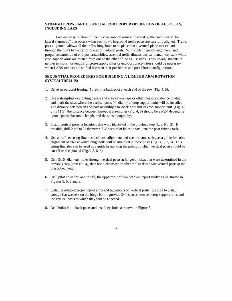
STRAIGHT ROWS ARE ESSENTIAL FOR PROPER OPERATION OF ALL OSSTS,INCLUDING LARS
Free and easy rotation of LARS' crop-support arms is fostered by the condition of "bi-lateral symmetry" that occurs when each row's in-ground trellis posts are carefully aligned. Trellispost alignment allows all the trellis' hingebolts to be placed on a vertical plane that extendsthrough the row's two exterior braces or tie-back posts. With such hingebolt alignment, andproper construction of end-post assemblies, essential trellis dimensions can remain constant whilecrop-support arms are rotated from one to the other of the trellis' sides. Thus, re-adjustments inneither tensions nor lengths of crop-support wires or end-post brace-wires should be necessarywhen LARS trellises are shifted between their pre-bloom and post-bloom configurations.
SEQUENTIAL PROCEDURES FOR BUILDING A LIMITED ARM ROTATIONSYSTEM TRELLIS:
1. Drive an outward-leaning (10-20°) tie-back post at each end of the row (Fig. 4, 5).
2. Use a string-line or sighting device and a surveyors tape or other measuring device to alignand mark the sites where the vertical posts (4” diam.) of crop support units will be installed.The distance between an end-post assembly’s tie-back post and its crop-support unit (Fig. 4-6) is 11.5’; the distance between line-post assemblies (Fig. 4, 8) should be 25-35’ dependingupon a particular row’s length, and the sites topography.
3. Install vertical posts at locations that were identified in the previous step (item No. 2). Ifpossible, drill 2 ½” to 3” diameter, 3-4' deep pilot holes to facilitate the post driving task.
4. Use an off-set string-line to check post alignment and use the same string as a guide for strictalignment of sites at which hingebolts will be mounted in these posts (Fig. 3, 5, 7, 8). Thisstring-line also can be used as a guide in marking the points at which vertical posts should becut off or decapitated (Fig.3, 5, 6 ,8).
5. Drill 9/16” diameter holes through vertical posts at hingebolt sites that were determined in theprevious step (item No. 4), then use a chainsaw or other tool to decapitate vertical posts at theprescribed height.
6. Drill pilot holes for, and install, the uppermost of two “cable-support studs” as illustrated inFigures 3, 5, 6 and 8.
7. Install pre-drilled crop-support arms and hingebolts on vertical posts. Be sure to installenough flat washers on the hinge bolt to provide 3/4” spaces between crop-support arms andthe vertical posts to which they will be attached.
8. Drill holes in tie-back posts and install eyebolts as shown in Figure 5.
6
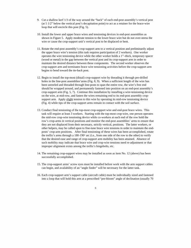
9. Cut a shallow kerf 1/3 of the way around the “back” of each end-post assembly’s vertical post(at 5 1/2” below the vertical post’s decapitation point) to act as a retainer for the brace-wireloop that will encircle this post (Fig. 5).
10. Install the lower and upper brace wires and tensioning devices in end-post assemblies asshown in Figure 5. Apply moderate tension to the lower brace wire but do not over-stress thewire or cause the crop-support unit’s vertical post to be displaced or bent.
11. Rotate the end-post assembly’s crop-support arm to a vertical position and preliminarily adjustthe upper brace wire’s tension (this task requires participation of 2 workers). One workeroperates the wire tensioning device while the other worker holds a 1”–thick, temporary spacer(wood or metal) in the gap between the vertical post and its crop-support arm in order tomaintain the desired distance between these components. The second worker observes thecrop-support arm and terminates brace wire tensioning activities before the crop-support armbegins to bend toward the tie-back post.
12. Begin to install the top-most (distal) crop-support wire by threading it through pre-drilledholes in the line-post assemblies’arms (Fig. 8, 9). When a sufficient length of the wire hasbeen unreeled and threaded through line-posts to span the entire row, the wire’s free endshould be wrapped around, and permanently fastened into position on an end-post assembly’scrop-support arm (Fig. 5, 7). Continue this installation by installing a wire-tensioning deviceon the wire, at mid-row, and fasten the wires remaining end to its end-post assembly crop-support arm. Apply slight tension to this wire by operating its mid-row tensioning device(Fig. 4) while tips of the crop-support arms remain in contact with the soil surface.
13. Conduct final tensioning of the top-most crop-support wire and end-post brace wires. Thistask will require at least 3 workers. Starting with the top-most crop-wire, one person operatesthe mid-row crop-wire tensioning device while co-workers at each end of the row hold therow’s crop-arms in vertical positions and monitor the end-post assemblies’ arms to ensure thatthey are not displaced from their necessary, strictly vertical, positions. The latter workers, orother helpers, may be called upon to fine-tune brace wire tensions in order to maintain the end-posts’ crop-arm positions. After final tensioning of these wires has been accomplished, rotatethe trellis’s arms through a 180-190° arc (i.e., from one side of the row to the other) to verifythat the desired ease and range of crop-support arm mobility has been attained. Absence ofsuch mobility may indicate that brace wire and crop-wire tensions need re-adjustment or thatimproper alignment exists among the trellis’s hingebolts, etc.
14. The remaining crop-support wires may be installed as soon as item No. 12 (above) has beensuccessfully accomplished.
15. The crop-support arms’ screw eyes must be installed before work with the arm support cablescan begin, and availability of an “angle finder” will be necessary for the latter task.
16. Each crop-support arm’s support cable (aircraft cable) must be individually sized and fastenedinto a loop that will hold this arm at a prescribed “pre-bloom” angle of declination (usually 70
7
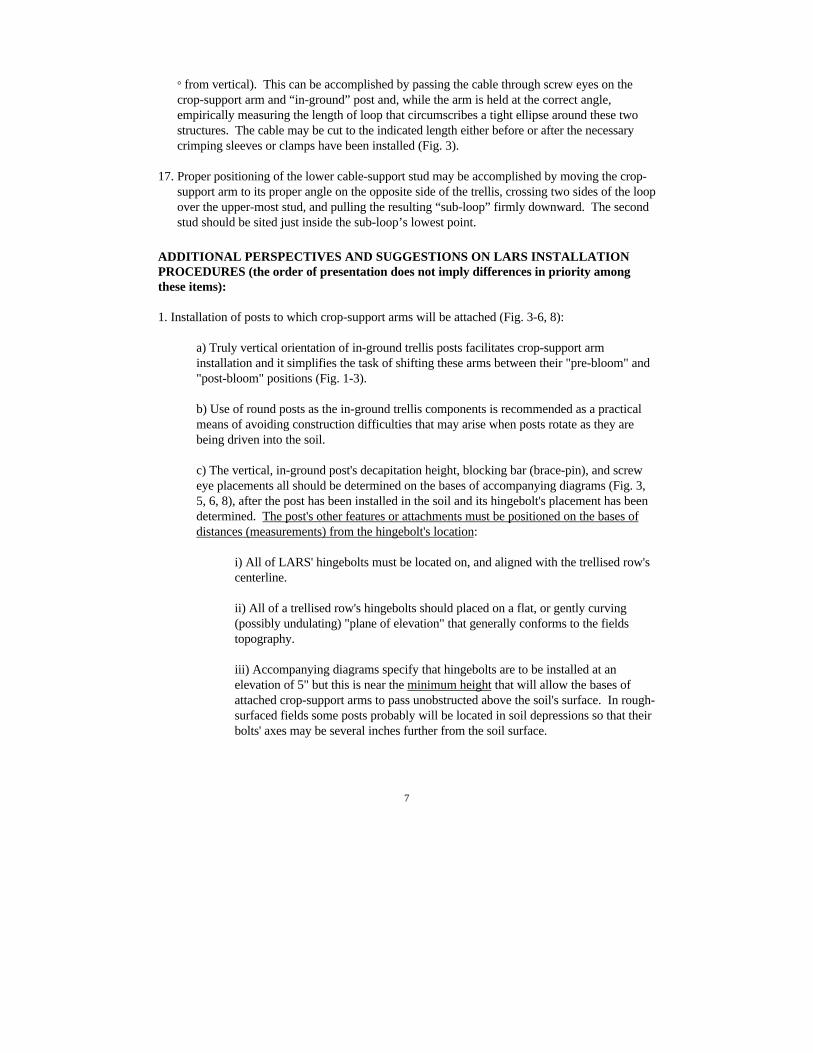
° from vertical). This can be accomplished by passing the cable through screw eyes on thecrop-support arm and “in-ground” post and, while the arm is held at the correct angle,empirically measuring the length of loop that circumscribes a tight ellipse around these twostructures. The cable may be cut to the indicated length either before or after the necessarycrimping sleeves or clamps have been installed (Fig. 3).
17. Proper positioning of the lower cable-support stud may be accomplished by moving the crop-support arm to its proper angle on the opposite side of the trellis, crossing two sides of the loopover the upper-most stud, and pulling the resulting “sub-loop” firmly downward. The secondstud should be sited just inside the sub-loop’s lowest point.
ADDITIONAL PERSPECTIVES AND SUGGESTIONS ON LARS INSTALLATIONPROCEDURES (the order of presentation does not imply differences in priority amongthese items):
1. Installation of posts to which crop-support arms will be attached (Fig. 3-6, 8):
a) Truly vertical orientation of in-ground trellis posts facilitates crop-support arminstallation and it simplifies the task of shifting these arms between their "pre-bloom" and"post-bloom" positions (Fig. 1-3).
b) Use of round posts as the in-ground trellis components is recommended as a practicalmeans of avoiding construction difficulties that may arise when posts rotate as they arebeing driven into the soil.
c) The vertical, in-ground post's decapitation height, blocking bar (brace-pin), and screweye placements all should be determined on the bases of accompanying diagrams (Fig. 3,5, 6, 8), after the post has been installed in the soil and its hingebolt's placement has beendetermined. The post's other features or attachments must be positioned on the bases ofdistances (measurements) from the hingebolt's location:
i) All of LARS' hingebolts must be located on, and aligned with the trellised row'scenterline.
ii) All of a trellised row's hingebolts should placed on a flat, or gently curving(possibly undulating) "plane of elevation" that generally conforms to the fieldstopography.
iii) Accompanying diagrams specify that hingebolts are to be installed at anelevation of 5" but this is near the minimum height that will allow the bases ofattached crop-support arms to pass unobstructed above the soil's surface. In rough-surfaced fields some posts probably will be located in soil depressions so that theirbolts' axes may be several inches further from the soil surface.
8
f) Some variations in topography (i.e., elevation) can be tolerated where shift-trellises willbe constructed, but the practical limits of such tolerance have not been ascertained.
g) Deep insertion (3' to 4') of line-posts seems important in preventing one-sided trellisesfrom capsizing; this applies as much (or more) to static-trellises as to shift-trellises.
2. Proper alignment, construction and maintenance of end-post brace assemblies (Fig. 2, 4, 5, 6-7;Table 1), including tie-back posts and anchors, is critical for shift-trellis integrity and operation:
a) Tie-back posts must be deeply and firmly installed in the soil, by use of a post driver orby thorough tamping or cementing in place, before tension is applied to either the crop-support wires or the end-post brace wires.
b) The tie-back post's eyebolt must be installed so that its eye is aligned with the row'scenterline and on the same horizontal plane as the end-post assembly's hinge bolt.
c) Brace-wire tensions (or lengths) must be adjusted, by use of in-line strainers (Fig. 5), sothat the crop-support arm and "in-ground post" are perpendicular to the eyebolt/hingeboltaxis. These tensions preliminarily are adjusted during installation of the end-postassembly, but they must be "fine-tuned" during subsequent installation and tightening ofthe crop-support wires (Fig. 4; Table 3).
d) Whenever crop-support wire tensions are being adjusted, it is critical that workers beassigned to monitor the end-post crop-support arms' positions and to adjust brace-wirestrainers so that the arms' perpendicularity is maintained.
3. Crop-support wires should be mounted through holes in the line-posts' crop-support arms inorder to avoid hazards that might arise if any wire(s) were to fail (break) during operation orconstruction of OSSTs; such a mounting technique seems more effective (than stapling of wires)in keeping the arms from twisting their hinge bolts.
4. Pre-drilling (with a drill press) of all necessary holes in crop-support arms (Fig. 7, 9) facilitatesproper alignment of crop-support wires that pass through these arms so that tensioning of thewires is more easily accomplished. Pre-drilling also increases the speed and efficiency of fieldconstruction activities.
5. Sizing and installation of crop-arm support cables (Fig. 3):
a) Full tension should be applied to the distal crop-support wire before the lengths of crop-arm support-cable loops are adjusted at any posts within a row.
b) Lengths of crop-arm support cables must be individually adjusted for each crop-supportarm in the planting. The necessary length of a support cable is determined while itsassociated crop-support arm is being held in the desired pre-bloom position and at thedesired angle of declination (usually 70o from vertical).
9
c) Widely available, low-cost "angle finders" have been very useful (nearly indispensable),during installation of LARS crop-support arms, for adjustment of crop-arm declinationsand support loop (i.e., cable) lengths.
d) A tool has been specially designed to aide in determining and marking the sites (onvertical posts) at which the lower cable-support stud must be located in order to achievethe desired angles of declination among post-bloom positioned crop-support arms.
6. A removable "blocking-bar" (9" x 3/8" brace-pin) is mounted in each vertical trellis post inorder to prevent wind from moving crop-support arms out of their seasonally prescribed positions(Fig. 3, 6).
RATIONALE OF THE NEW PRIMOCANE MANAGEMENT APPARATUS (PMA):
Primocane Management Apparatus (PMA) was derived primarily to improve conditionsfor annual cropping of blackberries and raspberries on SSST and LARS trellises. PMA will helpto protect primocanes from injuries by equipment, foot-traffic, or wind, and will tend to increasethe degree of spatial separation between primocanes and floricanes. Greater canopy separationshould increase the exposure of leaves to sunlight and allow freer air movement within both theprimocane and floricane canopies. PMA coincidentally should assist producers to maintainorderly appearing plantings that may be more attractive to U-pick patrons or custom harvestlaborers. Application of this technology may contribute to development of semi-mechanizedprocedures for removal of spent floricanes (i.e., old cane pruning).
INSTALLATION AND USE OF PRIMOCANE MANAGEMENT APPARATUS:
1. PMA's primocane support spars and twine should be installed after the trellis' crop-supportarms have been shifted to their post-bloom positions:
a) PMA can be installed, or "retro-fitted," on existing SSST or LARS trellises, inestablished plantings, during the "post-bloom" period in any particular season.
b) The sequences of plant development, trellis arm shifting, and other events in newplantings suggest that PMA not be installed before the post-bloom period of a newplantation's second growing season. This suggestion, through delay of materialacquisition and labor expenses, may allow the producer to reduce investment costs (i.e.,interest payments) of new enterprises in which the use of PMA is anticipated.
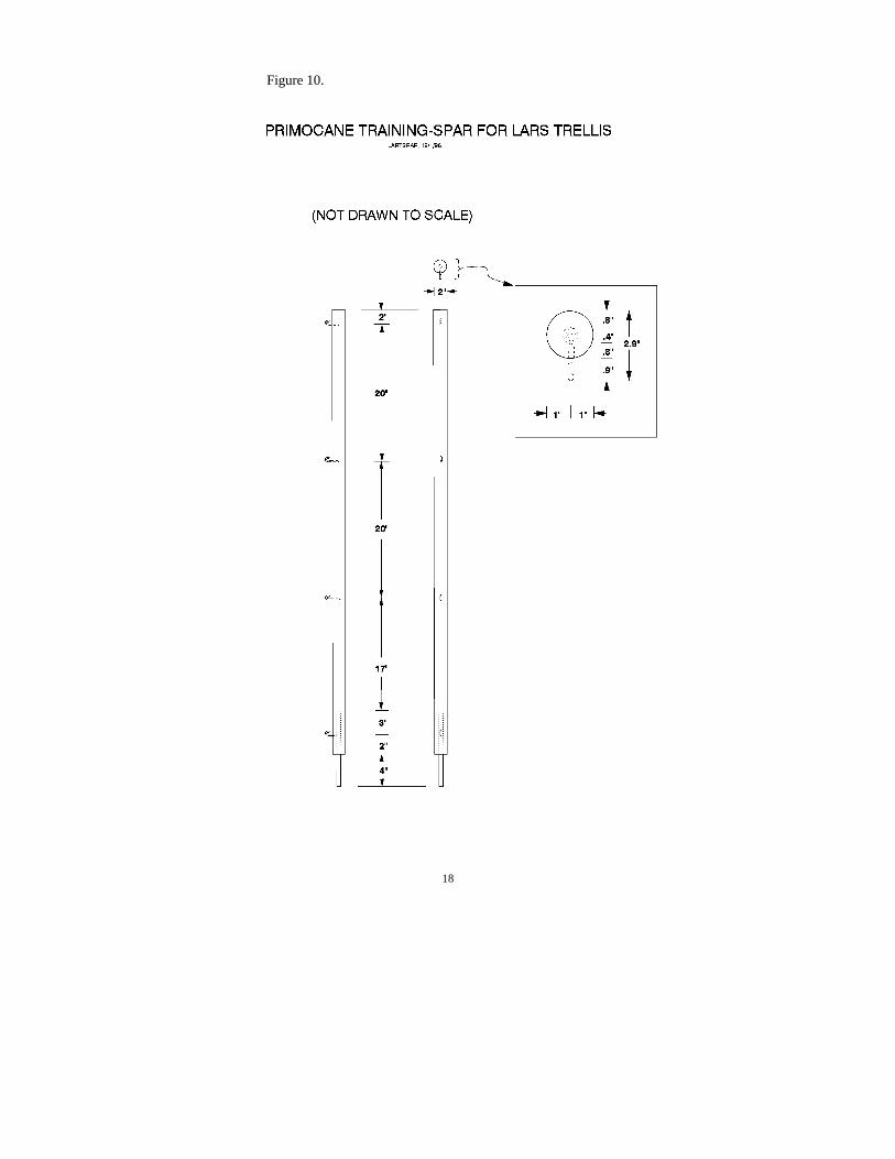
2. PMA consists of detachable, disposable, polypropylene primocane-training twines supportedby "J-hooks" or one-sided staples on rigid "primocane-support spars" (or extensions) that areremovably mounted atop the short, vertical posts in LARS' end-post and line-post assemblies (Fig.4, 8; 10 Table 5, 7):
10
a) Accurate positioning of J-hooks on primocane-support spars is needed to permit theprimocane canopy to be transferred en mass from PMA to the trellis' crop-support-arm.
i) Small variations in LARS or SSST trellis dimensions (especially heights ofvertical posts) may occur during field installation procedures and such variationsmay affect the exact positions at which J-hooks should be mounted along eachprimocane support spars' length.
ii) Proper J-hook positions will coincide with a trellis arm's crop-support wireswhen that arm is rotated into a vertical configuration, these positions can bedetermined after spars have been installed on trellis posts, by measuring theirprescribed distances from the trellis posts’ hingebolts.
iii) Thus, each spar is considered to be uniquely adapted for use with the trellispost on which it originally was installed; posts and spars should be permanentlymarked so that their future pairings can be assured (see also the section on PMAuse).
b) In order to achieve more effective adjustment of twine tautness, and to avoid undesiredeffects upon canopy positions, it is important that the specified tensioning devices beinstalled at or near their respective twines' mid-points rather than near the ends of thetrellised row.
3. Use of the primocane management apparatus:
a) Depending upon a cultivar's growth habit (propensity for sucker production), its in-rowplant spacing, and the morphology of its canes (particularly cane diameter), primocaneswill be trained vertically or in fan patterns for attachment to PMA's horizontal twines.
b) Additional research is needed to determine the numbers or spacings of primocanes thatmay be needed for optimal productivity, etc., of the various types or cultivars of bramblesthat may be trained on this type of trellis; densities of 2 to 3 canes per foot of row seemappropriate for initial trials of this system.
c) Primocanes probably should be trained and tied to the PMA at weekly intervals duringperiods of rapid primocane elongation; labor costs of primocane training may beminimized by use of semi-automated tying tools or "tapeners."
d) PMA's twines may tend to stretch and sag during warm weather, or when subjected tothe weight of attached primocanes, and their tautness must be adjusted just prior to eachprimocane training session. Laborers must be instructed to ensure that twines arepositioned at their desired elevations during the act of primocane attachment. Suchpositioning will facilitate the eventual transfer of twines and canes onto the trellis's crop-support arms.
11
e) Primocane training-twines, not canes per se, are tied to the trellis' crop-support wires.This should minimize the dormant-season's training-labor and material requirements andfacilitate the eventual, after-harvest, removal of these canes from the trellis.
f) During their transfer to the trellis' crop-support-arm, primocanes that are trained andtied to the twines' "inner-sides" will become sandwiched between training-twines andpermanent crop-support wires. This juxtaposition should strengthen the canopy'sattachment to crop-support wires so that wind will be very unlikely to dislodge canes fromthe trellis.
g) PMA's spars must be dismounted from the tops of trellis posts (after twines and caneshave been transferred to crop-support wires) so that the trellis's crop-support arms can beshifted to their pre-bloom positions. Spars can be stored in situ, on crop-support wires ateach spar's original crop-support arm location.
12
Figure 4.
13
Figure 5.
14
Figure 6.
15
Figure 7.
16
Figure 8.
17
Figure 9.
18
Figure 10.
19
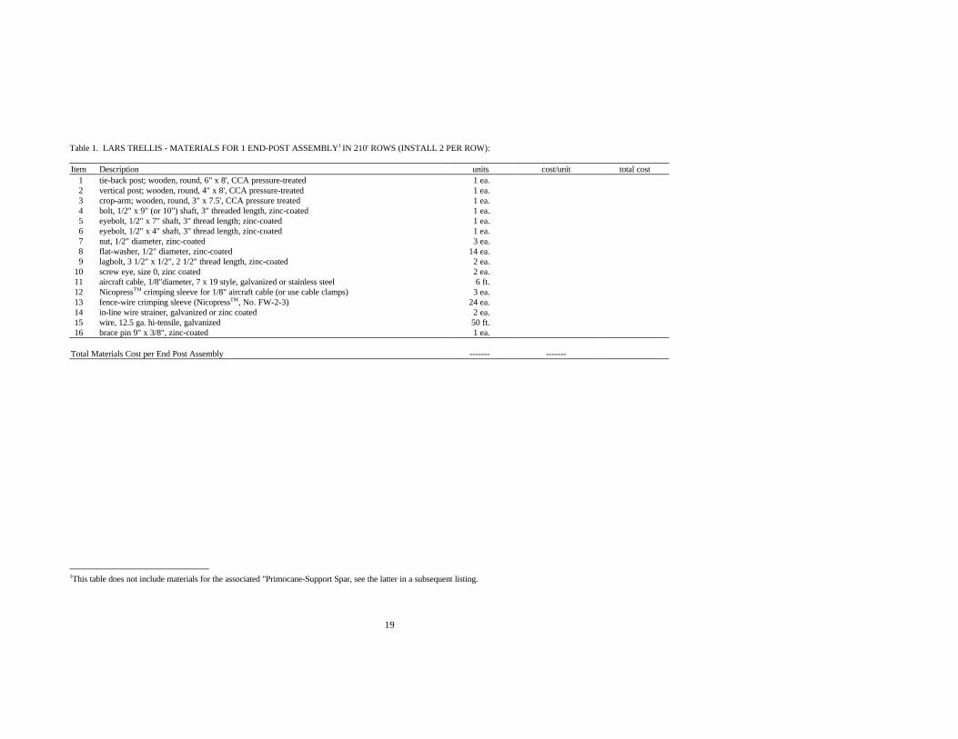
Table 1. LARS TRELLIS - MATERIALS FOR 1 END-POST ASSEMBLY1 IN 210' ROWS (INSTALL 2 PER ROW):
Item Description units cost/unit total cost1 tie-back post; wooden, round, 6" x 8', CCA pressure-treated 1 ea.2 vertical post; wooden, round, 4" x 8', CCA pressure-treated 1 ea.3 crop-arm; wooden, round, 3" x 7.5', CCA pressure treated 1 ea.4 bolt, 1/2" x 9" (or 10") shaft, 3" threaded length, zinc-coated 1 ea.5 eyebolt, 1/2" x 7" shaft, 3" thread length; zinc-coated 1 ea.6 eyebolt, 1/2" x 4" shaft, 3" thread length, zinc-coated 1 ea.7 nut, 1/2" diameter, zinc-coated 3 ea.8 flat-washer, 1/2" diameter, zinc-coated 14 ea.9 lagbolt, 3 1/2" x 1/2", 2 1/2" thread length, zinc-coated 2 ea.
10 screw eye, size 0, zinc coated 2 ea.11 aircraft cable, 1/8"diameter, 7 x 19 style, galvanized or stainless steel 6 ft.12 NicopressTM crimping sleeve for 1/8" aircraft cable (or use cable clamps) 3 ea.13 fence-wire crimping sleeve (NicopressTM, No. FW-2-3) 24 ea.14 in-line wire strainer, galvanized or zinc coated 2 ea.15 wire, 12.5 ga. hi-tensile, galvanized 50 ft.16 brace pin 9" x 3/8", zinc-coated 1 ea.
Total Materials Cost per End Post Assembly ------- -------
1This table does not include materials for the associated "Primocane-Support Spar, see the latter in a subsequent listing.
20
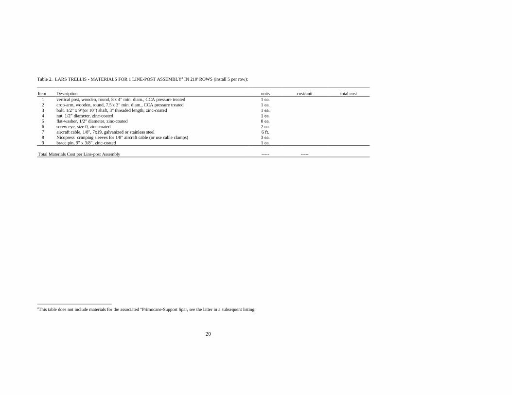
Table 2. LARS TRELLIS - MATERIALS FOR 1 LINE-POST ASSEMBLY2 IN 210' ROWS (install 5 per row):
Item Description units cost/unit total cost1 vertical post, wooden, round, 8'x 4" min. diam., CCA pressure treated 1 ea.2 crop-arm, wooden, round, 7.5'x 3" min. diam., CCA pressure treated 1 ea.3 bolt, 1/2" x 9"(or 10") shaft, 3" threaded length; zinc-coated 1 ea.4 nut, 1/2" diameter, zinc-coated 1 ea.5 flat-washer, 1/2" diameter, zinc-coated 8 ea.6 screw eye, size 0, zinc coated 2 ea.7 aircraft cable, 1/8", 7x19, galvanized or stainless steel 6 ft.8 Nicopress crimping sleeves for 1/8" aircraft cable (or use cable clamps) 3 ea.9 brace pin, 9" x 3/8", zinc-coated 1 ea.
Total Materials Cost per Line-post Assembly ----- -----
2This table does not include materials for the associated "Primocane-Support Spar, see the latter in a subsequent listing.
21
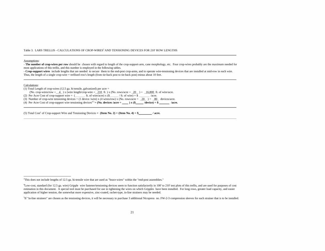
Table 3. LARS TRELLIS - CALCULATIONS OF CROP-WIRES3 AND TENSIONING DEVICES FOR 210' ROW LENGTHS
Assumptions:- The number of crop-wires per row should be chosen with regard to length of the crop-support-arm, cane morphology, etc. Four crop-wires probably are the maximum needed formost applications of this trellis, and this number is employed in the following tables.- Crop-support wires include lengths that are needed to secure them to the end-post crop-arms, and to operate wire-tensioning devices that are installed at mid-row in each wire.Thus, the length of a single crop-wire = trellised row's length (from tie-back post to tie-back post) minus about 10 feet.
Calculations:(1) Total Length of crop-wires (12.5 ga. hi-tensile, galvanized) per acre =
(No. crop-wires/row = 4 ) x (wire length/crop-wire = 210 ft. ) x (No. rows/acre = 20 ) = 16,800 ft. of wire/acre.(2) Per Acre Cost of crop-support wire = ( ft. of wire/acre) x ($ / ft. of wire) = $ /acre.(3) Number of crop-wire tensioning devices = (1 device /wire) x (4 wires/row) x (No. rows/acre = 20 ) = 80 devices/acre.(4) Per Acre Cost of crop-support wire tensioning devices4,5 = (No. devices /acre = ) x ($ /device) = $ /acre.
(5) Total Cost1 of Crop-support Wire and Tensioning Devices = (Item No. 2) + (Item No. 4) = $ / acre.
3This does not include lengths of 12.5 ga. hi-tensile wire that are used as "brace-wires" within the "end-post assemblies."
4Low-cost, standard (for 12.5 ga. wire) Gripple wire fastener/tensioning devices seem to function satisfactorily in 100' to 210' test plots of this trellis, and are used for purposes of costestimation in this document. A special tool must be purchased for use in tightening the wires on which Gripples have been installed. For long rows, greater load capacity, and easierapplication of higher tension, the somewhat more expensive, zinc-coated, rachet-type, in-line strainers may be needed.
5If "in-line strainers" are chosen as the tensioning devices, it will be necessary to purchase 3 additional Nicopress no. FW-2-3 compression sleeves for each strainer that is to be installed.
22
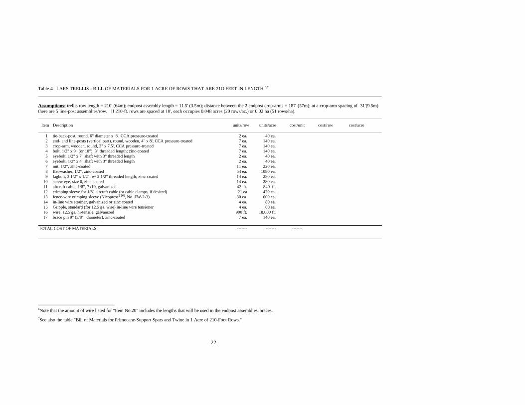
Table 4. LARS TRELLIS - BILL OF MATERIALS FOR 1 ACRE OF ROWS THAT ARE 21O FEET IN LENGTH 6,7
Assumptions: trellis row length = 210' (64m); endpost assembly length = 11.5' (3.5m); distance between the 2 endpost crop-arms = 187' (57m); at a crop-arm spacing of 31'(9.5m)there are 5 line-post assemblies/row. If 210-ft. rows are spaced at 10', each occupies 0.048 acres (20 rows/ac.) or 0.02 ha (51 rows/ha).
Item Description units/row units/acre cost/unit cost/row cost/acre
1 tie-back-post, round, 6" diameter x 8', CCA pressure-treated 2 ea. 40 ea.2 end- and line-posts (vertical part), round, wooden, 4" x 8', CCA pressure-treated 7 ea. 140 ea.3 crop-arm, wooden, round, 3" x 7.5', CCA pressure-treated 7 ea. 140 ea.4 bolt, 1/2" x 9" (or 10"), 3" threaded length; zinc-coated 7 ea. 140 ea.5 eyebolt, 1/2" x 7" shaft with 3" threaded length 2 ea. 40 ea.6 eyebolt, 1/2" x 4" shaft with 3" threaded length 2 ea. 40 ea.7 nut, 1/2", zinc-coated 11 ea. 220 ea.8 flat-washer, 1/2", zinc-coated 54 ea. 1080 ea.9 lagbolt, 3 1/2" x 1/2", w/ 2 1/2" threaded length; zinc-coated 14 ea. 280 ea.
10 screw eye, size 0, zinc coated 14 ea. 280 ea.11 aircraft cable, 1/8", 7x19, galvanized 42 ft. 840 ft.12 crimping sleeve for 1/8" aircraft cable (or cable clamps, if desired) 21 ea 420 ea.13 fence-wire crimping sleeve (NicopressTM, No. FW-2-3) 30 ea. 600 ea.14 in-line wire strainer, galvanized or zinc coated 4 ea. 80 ea.15 Gripple, standard (for 12.5 ga. wire) in-line wire tensioner 4 ea. 80 ea.16 wire, 12.5 ga. hi-tensile, galvanized 900 ft. 18,000 ft.17 brace pin 9" (3/8"" diameter), zinc-coated 7 ea. 140 ea.
TOTAL COST OF MATERIALS ------- ------- -------
6Note that the amount of wire listed for "Item No.20" includes the lengths that will be used in the endpost assemblies' braces.
7See also the table "Bill of Materials for Primocane-Support Spars and Twine in 1 Acre of 210-Foot Rows."
23
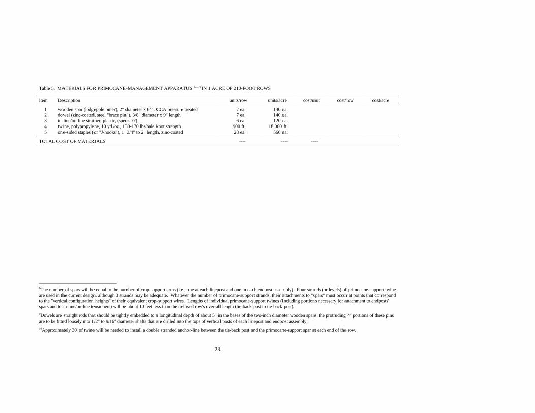
Table 5. MATERIALS FOR PRIMOCANE-MANAGEMENT APPARATUS 8,9,10 IN 1 ACRE OF 210-FOOT ROWS
Item Description units/row units/acre cost/unit cost/row cost/acre
1 wooden spar (lodgepole pine?), 2" diameter x 64", CCA pressure treated 7 ea. 140 ea.2 dowel (zinc-coated, steel "brace pin"), 3/8" diameter x 9" length 7 ea. 140 ea.3 in-line/on-line strainer, plastic, (spec's ??) 6 ea. 120 ea.4 twine, polypropylene, 10 yd./oz., 130-170 lbs/bale knot strength 900 ft. 18,000 ft.5 one-sided staples (or "J-hooks"), 1 3/4" to 2" length, zinc-coated 28 ea. 560 ea.
TOTAL COST OF MATERIALS ---- ---- ----
8The number of spars will be equal to the number of crop-support arms (i.e., one at each linepost and one in each endpost assembly). Four strands (or levels) of primocane-support twineare used in the current design, although 3 strands may be adequate. Whatever the number of primocane-support strands, their attachments to "spars" must occur at points that correspondto the "vertical configuration heights" of their equivalent crop-support wires. Lengths of individual primocane-support twines (including portions necessary for attachment to endposts'spars and to in-line/on-line tensioners) will be about 10 feet less than the trellised row's over-all length (tie-back post to tie-back post).
9Dowels are straight rods that should be tightly embedded to a longitudinal depth of about 5" in the bases of the two-inch diameter wooden spars; the protruding 4" portions of these pinsare to be fitted loosely into 1/2" to 9/16" diameter shafts that are drilled into the tops of vertical posts of each linepost and endpost assembly.
10Approximately 30' of twine will be needed to install a double stranded anchor-line between the tie-back post and the primocane-support spar at each end of the row.

24
Table 6. LARS TRELLIS - BILL OF MATERIALS FOR ROWS THAT ARE 5OO FEET IN LENGTH 11,12
Assumptions: trellis row length = 500' (152.4m); endpost assembly length = 11.5' (3.5m); distance between the 2 endpost crop-arms = 477' (145.4m); at a crop-arm spacing of 34'(10.4m) there are 13 line-post assemblies/row. If 500-ft. rows are spaced at 10'10", each occupies 0.124 acres (8 rows/ac.) or 0.05 ha (20 rows/ha).Note that the tie-back posts' 8" diameter is larger than specified for shorter (210') rows, so their cost will be greater. Similarly, 4"-5" diameters are suggested for the endposts' crop-arms. The latterchanges make larger bolts, eyebolts, nuts and flat washers necessary for use in the endpost assemblies; thus, 5/8" diameter items are all intended for use in endpost assemblies. It may be necessary toaugment the endpost assemblies' wire braces and cables, but these possibilities are not reflected in the following bill of materials. Item Description units/row units/acre cost/unit cost/row cost/acre
1 tie-back-post, round, 8" diameter, 8' length, CCA pressure-treated. 2 ea. 16 ea.2 endpost (vertical part), round, wooden, 6" x 8' length, CCA press. treated. 2 ea. 16 ea.3 endpost crop-arm, round, wooden, 4"or 5" x 8' length, CCA press. treated. 2 ea. 16 ea.4 linepost (vertical part) wooden, round, 4" x 8' length, CCA pressure-treated. 13 ea. 104 ea.5 linepost crop-arm, wooden post, round, 3" diam. x 7.5', CCA press. treated. 13 ea. 104 ea.6 bolt, 1/2" x 8", 2" threaded length; zinc-coated. 13 ea. 104 ea.7 bolt, 5/8" x 10", 4" threaded length; zinc-coated. 2 ea. 16 ea.8 eyebolt, 5/8" diameter, 10" shaft with 3" threaded length; zinc-coated. 2 ea. 16 ea.9 eyebolt, 5/8" diameter shaft, 8" shaft-length with 4" threads; zinc-coated. 2 ea. 16 ea.
10 nut, 5/8", zinc-coated (?/lb). 6 ea. 48 ea.11 nut, 1/2", zinc-coated (28/lb?). 13 ea. 104 ea.12 flat-washer, 1/2", zinc-coated (24/lb?). 134 ea. 1072 ea.13 flat-washer, 5/8", zinc-coated (? /lb). 20 ea. 160 ea.14 lagbolt, 3 1/2" x 1/2", w/ 2 1/2" threaded length; zinc-coated. 30 ea. 240 ea.15 screw eye, size 0, zinc coated. 30 ea. 240 ea.16 aircraft cable, 1/8", 7x19, galvanized. 77 ft. 616 ft.17 crimping sleeve for 1/8" aircraft cable (or cable clamps, if desired). 45 ea. 360 ea.18 fence-wire crimping sleeve (NicopressTM, No. FW-2-3). 60 ea. 480 ea.19 in-line wire strainer, galvanized or zinc coated. 8 ea. 64 ea.20 wire, 12.5 ga. hi-tensile, galvanized. 2060 ft. 16,480 ft.21 brace pin 9" (1/2" diam.?), zinc-coated 15 ea. 120 ea.
TOTAL MATERIALS COST ----- ----
1111Note that the amount of wire listed for "Item No.20" includes the lengths that will be used in the endpost assemblies' braces.
1122See also the table "Items for installation of Primocane-Support Spars and Twine in 500-ft. Rows."
25
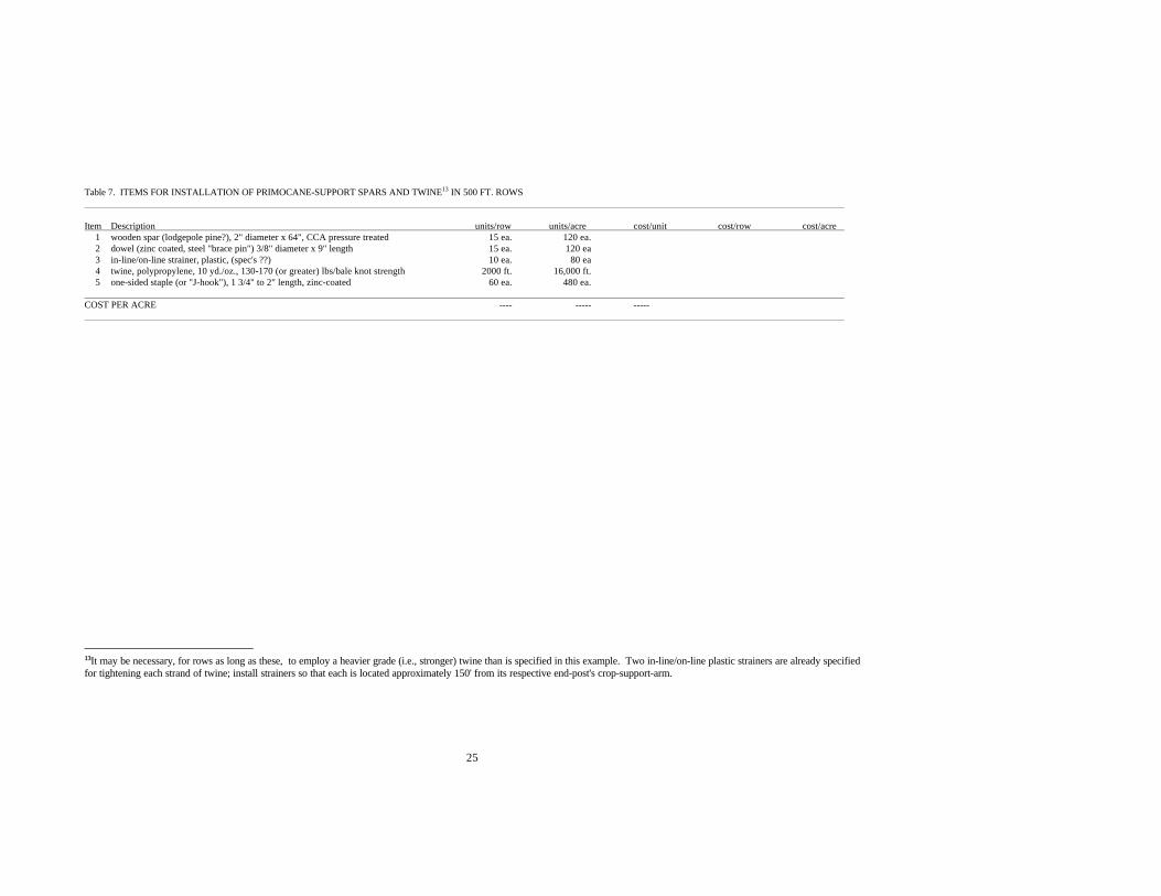
Table 7. ITEMS FOR INSTALLATION OF PRIMOCANE-SUPPORT SPARS AND TWINE13 IN 500 FT. ROWS
Item Description units/row units/acre� cost/unit� cost/row cost/acre 1 wooden spar (lodgepole pine?), 2" diameter x 64", CCA pressure treated 15 ea. 120 ea.2 dowel (zinc coated, steel "brace pin") 3/8" diameter x 9" length� 15 ea. 120 ea3 in-line/on-line strainer, plastic, (spec's ??) 10 ea. 80 ea4 twine, polypropylene, 10 yd./oz., 130-170 (or greater) lbs/bale knot strength 2000 ft. 16,000 ft.5 one-sided staple (or "J-hook"), 1 3/4" to 2" length, zinc-coated 60 ea. 480 ea.
COST PER ACRE ---- ----- -----
1133It may be necessary, for rows as long as these, to employ a heavier grade (i.e., stronger) twine than is specified in this example. Two in-line/on-line plastic strainers are already specifiedfor tightening each strand of twine; install strainers so that each is located approximately 150' from its respective end-post's crop-support-arm.
26
LITERATURE CITED
Stiles, H.D. 1995a. Shift-Trellises for Better Management of Brambles (Rubus cvs.). Bulletin 95-2. Blacksburg, Va.: Virginia Agricultural Experiment Station, 46 pp. Available:http://www.vaes.vt.edu/research/publications/index.html. 16 December 1996.
Stiles, H.D. 1995b. Bramble production practices in Virginia. Pp. 13-16 In Proceedings 1995Illinois Cooperative Extension Service, Horticulture Series 99, ed. J.D. Kindhart. Simpson, Ill.:Dixon Springs Agricultural Center.
Stiles, H.D. 1996. Training and pruning semi-erect blackberries for fresh harvest. Pp. 33-37 In1996. NABGA Conference Proc. Portland, Ore.: North American Bramble Growers Association.
Stiles, H.D. and W.M. Tilson, 1998 (abstract). Temperatures differ between fronts and backs ofshaded and sunlit berries. HortScience 33(4):602.
Tilson, W.M. and H.D. Stiles. 1998 (abstract). Adaptation of a close-focus pyrometer for rapidcollection of blackberry fruit temperature data. HortScience 33(4):602.
27
APPENDIX
Drawings of a Single-Wire, Limited Arm-Rotation Trellis
Figure No. Subject Page No.
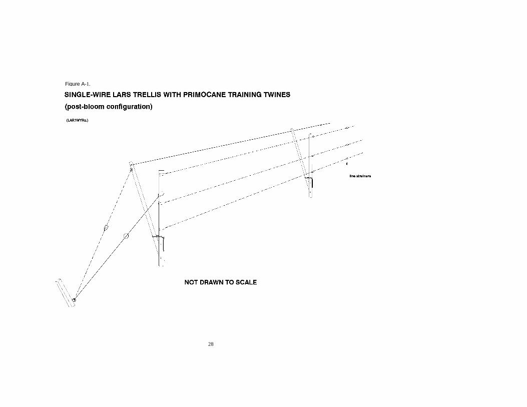
A-1 Single-wire LARS trellis with primocane training twines 28(post-bloom configuration).
A-2 Single-wire LARS trellis with training twines not shown 29(post-bloom configuration).
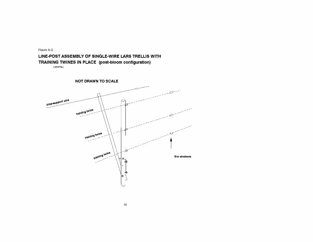
A-3 Line-post assembly of single-wire LARS trellis with training 30twines in place (post-bloom configuration).
28
Figure A-1.

29
Figure A-2.
30
Figure A-3.


![Stress state in the tapered beam bending – Analytical and … · 2019-09-02 · prismatic beams are also used but less frequently. Gere and Timoshenko [7] described the distribution](https://static.fdocuments.pl/doc/165x107/5ee02890ad6a402d666b65a1/stress-state-in-the-tapered-beam-bending-a-analytical-and-2019-09-02-prismatic.jpg)