Kubota 2420
71
KUBOTA CORPORATION 29- 9 HONGO 3-CH OME ,BUNKYO-KU,TOKYO 113 -0033,JAPAN [38 Pages ] FX0241107 TABLE-TOP CENTRI FUGE October 2005, Printed in Japan To ensure pr ope rope rat io n of th e centrif ug e, be sure to read th is manu al carefull y before operati ng it. Also, keep this manual handy so that you can refer to it at any time. NOTE For informat ion added or modif ied af ter Nove mber 2005, pl ease cont ac t your loca l deal er . ■The pr odu cts bein g indicated in this Instruction Manual ar e de si gned fo r opera- tors with expert knowledge and are intended only to beused by such qualified operat or s observin g the indi cated precau ti ons for respec ti ve purposes. For per- sons la cking nece ssar y ex pe rt kn owledg e, these pr od ucts may be di ff ic ul t to use properly and may even pose a danger to use. Wh en the aforesaid persons lack- ing the necessary expert knowled ge are using these products, do so under ap- propriate supervision and guid ance of a quali fi ed operator possessing the neces- sar y expert knowledge . ■Do not distribute th is manual wi th in the U.S. A. , Mexico, Can ada and Au st ralia as the pr od uc ts adve rt ised in the manu al sh al l not be di st ri buted in thes e countr ies. INSTRUCTION AND SERVICE MANUAL
-
Upload
dodik-e-prasetyo -
Category
Documents
-
view
234 -
download
0
Transcript of Kubota 2420
7/25/2019 Kubota 2420
http://slidepdf.com/reader/full/kubota-2420 1/70
KUBOTA CORPORATION
29-9 HONGO 3-CHOME,BUNKYO-KU,TOKYO 113-0033,JAPAN
[38 Pages]FX0241107
TABLE-TOP CENTRIFUGE
October 2005, Printed in Japan
To ensure proper operation of the centrifuge, be sure to read this manualcarefully before operating it.
Also, keep this manual handy so that you can refer to it at any time.
NOTE
For information added or modified after November 2005, please contact your local dealer.
■The products being indicated in this Instruction Manual are designed for opera-tors with expert knowledge and are intended only to be used by such qualifiedoperators observing the indicated precautions for respective purposes. For per-sons lacking necessary expert knowledge, these products may be difficult to use
properly and may even pose a danger to use. When the aforesaid persons lack-ing the necessary expert knowledge are using these products, do so under ap-propriate supervision and guidance of a qualified operator possessing the neces-sary expert knowledge.
■Do not distribute this manual within the U.S.A., Mexico, Canada and Australia asthe products advertised in the manual shall not be distributed in these countries.
INSTRUCTION AND
SERVICE MANUAL
7/25/2019 Kubota 2420
http://slidepdf.com/reader/full/kubota-2420 2/70
WARRANTY
Kubota Corporation ("Kubota") warrants that the instrument covered by this warranty shall be
free from defects in material and workmanship under normal use. Kubota will repair or replace,
free of all charges, the instrument which, within one (1) year after delivery or fifteen (15) months
after shipping, whichever comes earlier is proved to the satisfaction of Kubota to have been
defective at the time of delivery, provided that it does not fall under the exceptions and conditions
specified in this warranty. Such exception and conditions include, but are not limited to, failure
due to natural wear and tear, accident, negligence, alteration, repair, or operation in a manner not
prescribed in the Instruction Manual supplied with the instrument. The foregoing expresses
Kubotas sole warranty with respect to the instrument.
THIS WARRANTY IS MADE IN LIEU OF ANY AND ALL OTHER WARRANTIES AND ALL
IMPLIED WARRANTIES OF MERCHANTABILITY AND FITNESS FOR A PARTICULAR
PURPOSE ARE HEREBY DISCLAIMED AND EXCLUDED.
Kubota and its authorized dealers will not be liable for any consequential damages, loss or
expense arising from the improper use of the instrument. Kubota will not honor any other
warranty, which may be given, by its representative or dealer or otherwise which is different fromthe warranty given hereunder. This warranty is not assignable and is operative only in favor of the
original customer to whom this warranty is originally delivered.
Use of Model 2420
Model 2420 can be used for preprocessing in in-vitro analysis, which breaks down blood or urine
samples containing plasmas or cells. Accordingly, it is not designed to connect directly to a patient's body.
Do not use the centrifuge for separation of any hazardous material (explosive, chemically active,
organic, or radiation containing material, or material contaminated by pathogenic microorganisms)
or oil.
Copyright C 1995 KUBOTA Manufacturing Corporation
7/25/2019 Kubota 2420
http://slidepdf.com/reader/full/kubota-2420 3/70
■“Serious injury" is defined as injuries such as loss of eyesight, burn ( high / low temperature ),
electric shock, fracture of bone, poisoning causing aftereffects, or any other injuries requiring a
long-term medical treatment at hospital.
■“Non-fatal injury" is defined as burns, electric shock, or any other injuries which does not
require long-term medical treatment at hospital. "Property damage" is defined as expansion
damage related to damage to equipment or other properties.
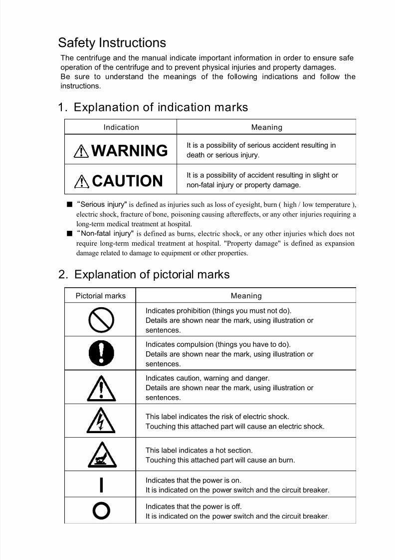
Safety InstructionsThe centrifuge and the manual indicate important information in order to ensure safe
operation of the centrifuge and to prevent physical injuries and property damages.
Be sure to understand the meanings of the following indications and follow the
instructions.
2. Explanation of pictorial marks
1. Explanation of indication marks
WARNING
CAUTION
Indication Meaning
It is a possibility of serious accident resulting in
death or serious injury.
It is a possibility of accident resulting in slight or
non-fatal injury or property damage.
Pictorial marks Meaning
Indicates prohibition (things you must not do).
Details are shown near the mark, using illustration or
sentences.
Indicates compulsion (things you have to do).
Details are shown near the mark, using illustration or
sentences.
Indicates caution, warning and danger.
Details are shown near the mark, using illustration or
sentences.
This label indicates the risk of electric shock.
Touching this attached part will cause an electric shock.
This label indicates a hot section.
Touching this attached part will cause an burn.
Indicates that the power is on.
It is indicated on the power switch and the circuit breaker.
Indicates that the power is off.
It is indicated on the power switch and the circuit breaker.
7/25/2019 Kubota 2420
http://slidepdf.com/reader/full/kubota-2420 4/70
page
Safety Instructions
General Notes・・・・・・・・・・・・・・・・・・・・・・Ⅰ
Usable Rotor ・・・・・・・・・・・・・・・・・・・・・・・Ⅳ
Lifetime of rotors・・・・・・・・・・・・・・・・・・・Ⅳ
Number of times allowed for
autoclaving of rotor ・・・・・・・・・・・・・・・・Ⅴ
Section 1.
Component Name and Explanation
1-1.Appearance・・・・・・・・・・・・・・・・・・・・・1-1
1-2.Control Panel ・・・・・・・・・・・・・・・・・・・1-2
Section 2.
Installation and Power Supply
2-1.Unpacking・・・・・・・・・・・・・・・・・・・・・・2-1
2-2.Place of Installation ・・・・・・・・・・・・・・2-1
2-3.Movement of centrifuge・・・・・・・・・・・2-1
2-4.Power Requirement・・・・・・・・・・・・・・・2-2
2-5.Grounding・・・・・・・・・・・・・・・・・・・・・・2-3
Section 3. Operation
3-1.Cautions of Operation・・・・・・・・・・・・・3-1
3-2.Operation ・・・・・・・・・・・・・・・・・・・・・3-1
3-3.Opening and Closing the lid・・・・・・・・3-4
[1]Turning on the power and opening
the lid・・・・・・・・・・・・・・・・・・・・・・・・・3-4
[2]Opening the lid during power failure・3-4
[3]Closing the lid・・・・・・・・・・・・・・・・・・3-5
3-4.Setting the Speed・・・・・・・・・・・・・・・・・3-6
[1] Setting the speed by the rpm・・・・・・・3-6
[2] Setting the speed by the centrifugal
force(× g)・・・・・・・・・・・・・・・・・・・・3-7
page
3-5.Setting the Timer ・・・・・・・・・・・・・・・・3- 8
3-6.Setting the acceleration ・ deceleration
・・・・・・・・・・・・・・・・・・・・・・・・・・・・・・3- 9
3-7.Saving the Memory・・・・・・・・・・・・・・3-10
[1]Saving the Memory・・・・・・・・・・・・・3-10
[2]Memory cancellation・・・・・・・・・・・・3-10
3-8.Setting the Function・・・・・・・・・・・・・3-11
[1]Setting the Rotation Radius・・・・・・・3-12
[2]Setting the “ SLOW" deceleration
・・・・・・・・・・・・・・・・・・・・・・・・・・・・・3-13
[3]Setting the Sound that informs
the end of the operation・・・・・・・・・・3-14
[4]Reverse of setting order of
the Speed and the Timer ・・・・・・・3-15
[5]Setting the Reminder alarm・・・・・・・3-16
[6]Setting the Indicators for
the end of the operation ・・・・・・・3-173-9.Calculating Centrifugal Force・・・・・・3-18
3-10.Allowable load and
Reduced maximum speed ・・・・・・3-18
Section 4. Service
4-1.Daily Inspection・・・・・・・・・・・・・・・・・4-1
4-2.Monthly Inspections・・・・・・・・・・・・・4-2
4-3.Annual Inspection・・・・・・・・・・・・・・・4-2
4-4.Cleaning and Sterilization・・・・・・・・・4-3
[1]Cleaning the chamber interior ・・・・・・4-3
[2]Cleaning the rotor, buckets and
tube rack ・・・・・・・・・・・・・・・・・・・・・・4-4
[3]Sterilization of rotor, buckets and
tube rack ・・・・・・・・・・・・・・・・・・・・・・4-4
4-5.Greasing・・・・・・・・・・・・・・・・・・・・・・・4-5
4-6.Inspection of Circuit Protector ・・・・・4-6
4-7.Using the Photoelectric Tachometer Port
・・・・・・・・・・・・・・・・・・・・・・・・・・・・・・4-7
Table of Contents
7/25/2019 Kubota 2420
http://slidepdf.com/reader/full/kubota-2420 5/70
page
4-8.Spare Parts Supply・・・・・・・・・・・・・・4- 8
4-9.Manufacturer requirements at Repair
or Maintenance・・・・・・・・・・・・・・・・4- 8
4-10.Product Preparation When Returning
Units for Repair or for Other Reasons
・・・・・・・・・・・・・・・・・・・・・・・・・・・・・4- 9
Contaminant Elimination Certificate
・・・・・・・・・・・・・・・・・・・・・・・・・・・・4-10
Section 5. Troubleshooting
5-1.Alarm Indicators・・・・・・・・・・・・・・・・・5-1
E0・・・・・・・・・・・・・・・・・・・・・・・・・・・・5-1
C1・・・・・・・・・・・・・・・・・・・・・・・・・・・・5-2
C2・・・・・・・・・・・・・・・・・・・・・・・・・・・・5-2
C3・・・・・・・・・・・・・・・・・・・・・・・・・・・・5-2
C4・・・・・・・・・・・・・・・・・・・・・・・・・・・・5-2
C5・・・・・・・・・・・・・・・・・・・・・・・・・・・・5-2
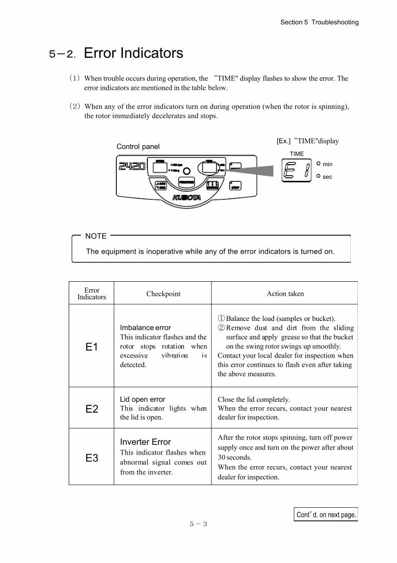
5-2.Error Indicators・・・・・・・・・・・・・・・・・・5-3
E1・・・・・・・・・・・・・・・・・・・・・・・・・・・・5-3
E2・・・・・・・・・・・・・・・・・・・・・・・・・・・・5-3
E3・・・・・・・・・・・・・・・・・・・・・・・・・・・・5-3
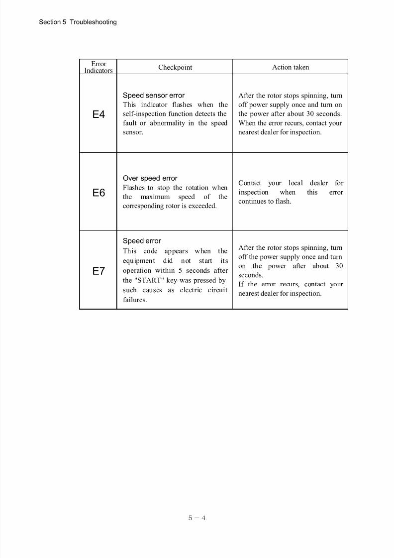
E4・・・・・・・・・・・・・・・・・・・・・・・・・・・・5-4
E6・・・・・・・・・・・・・・・・・・・・・・・・・・・・5-4
E7・・・・・・・・・・・・・・・・・・・・・・・・・・・・5-4
5-3.Troubleshooting・・・・・・・・・・・・・・・・・5-5
Section 6. Rotor
6-1.Mounting RS-240 Rotor ・・・・・・・・・・6- 1
6-2.Mounting RS-1004 Rotor
・・・・・・・・・6- 2
6-3.Mounting RMP-23 Rotor ・・・・・・・・・6- 3
6-4.RS-240 Swinging Bucket Rotor ・・・・6- 4
[1]Specification・・・・・・・・・・・・・・・・・・6- 4
[2]Setting Buckets・・・・・・・・・・・・・・・・6- 6
[3]Tube distribution method・・・・・・・・・6- 6
[4]Cushions / Adapter ・・・・・・・・・・・・・6- 7
6-5.RS-1004 Swinging Bucket Rotor ・・・6- 9
[1]Specification・・・・・・・・・・・・・・・・・・6- 9
[2]Setting Buckets・・・・・・・・・・・・・・・・6-10
[3]Tube distribution method・・・・・・・・・6-10
[4]Standard accessories・・・・・・・・・・・・6-10
page
6-6.RMP-23 Swinging Bucket Rotor ・・・6-11
[1]Specification・・・・・・・・・・・・・・・・・・6-11
[2]Check the trunnion pin・・・・・・・・・・・6-12
[3]Setting Buckets・・・・・・・・・・・・・・・・6-12
[4]Distribution of samples・・・・・・・・・・6-13
[5]Setting plate・・・・・・・・・・・・・・・・・・・6-13
[6]Allowable weight of plate・・・・・・・・6-14
[7]Standard accessories・・・・・・・・・・・・6-14
Section 7. Specifications
7-1.Centrifuge・・・・・・・・・・・・・・・・・・・・・・7-1
7-2.Standard Accessories・・・・・・・・・・・・・7-1
Section 8. Parts List
8-1.Recommended Spare Parts・・・・・・・・・8-1
Index
7/25/2019 Kubota 2420
http://slidepdf.com/reader/full/kubota-2420 6/70
7/25/2019 Kubota 2420
http://slidepdf.com/reader/full/kubota-2420 7/70
Grounding
Installation
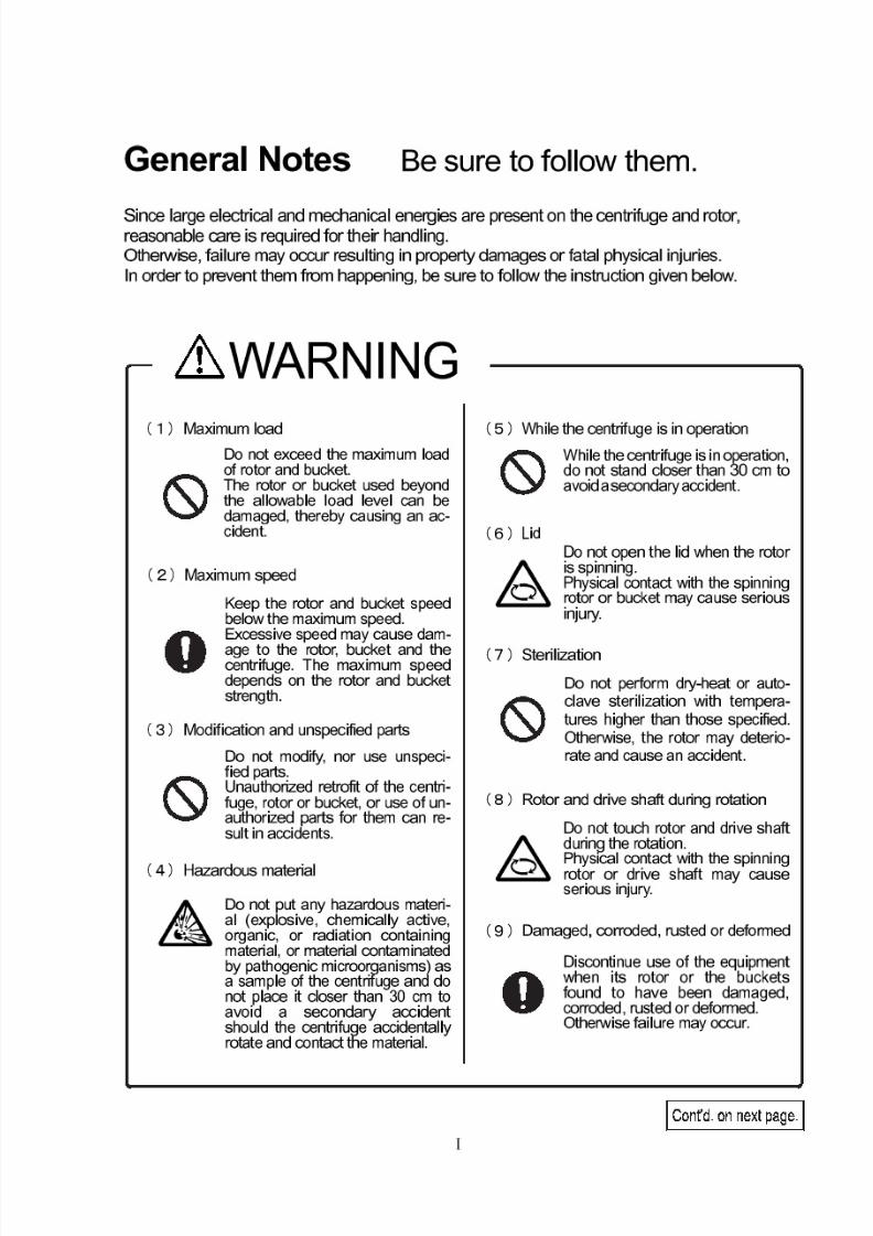
WARNING
Do not connect the ground cableto the following places:
1. Gas pipingExplosion or fire may occur.
2. Ground cable of lightningConductor, or telephone cable.Electric shock may occur in thecase of lightening.
A clearance of 30 cm minimummust be provided around the cen-trifuge.If the centrifuge is driven into un-
controlled rotations due to a fail-ure, secondary damage can resultfrom energy absorbed by the rota-tion.
Do not install the centrifuge on aninclined, slippery, or unstable sur-face.
Violent vibration may occur.
Ensure that the ground cable isconnected to the grounding termi-nal.
This precaution must be strictlyobserved to avoid accidents dueto electric shocks or leakage.
Installation
CAUTION
3. Water pipes
Do not install the centrifuge in a placewith high humidity (relative humidity 85%or above).
Leak or accident may occur.
Do not install the centrifuge in a placewith poor ventilation.
Otherwise inside temperature of the cen-trifuge may rise, resulting in accidents.
Do not install the centrifuge in a dustyplace.
Do not install the centrifuge in aplace where the temperature is
below 10 or over 40 . A place with the ambient tempera-
ture beyond 40 can introduce
undesirable build-up of heat insidethe centrifuge and a place under 10 can cause the centrifuge
malfunction and, as the result, ac-
cidents.
Lifetime of rotors
Use of rotors beyond the lifetime
may lead to breakage of the rotor.
If the rotor is used continuouslyeven after the lifetime of the rotor has expired, should the rotor getdamaged an accident may occur.
City water pipes may not beadequate as a ground since it
may consist of plastic piping.
7/25/2019 Kubota 2420
http://slidepdf.com/reader/full/kubota-2420 8/70
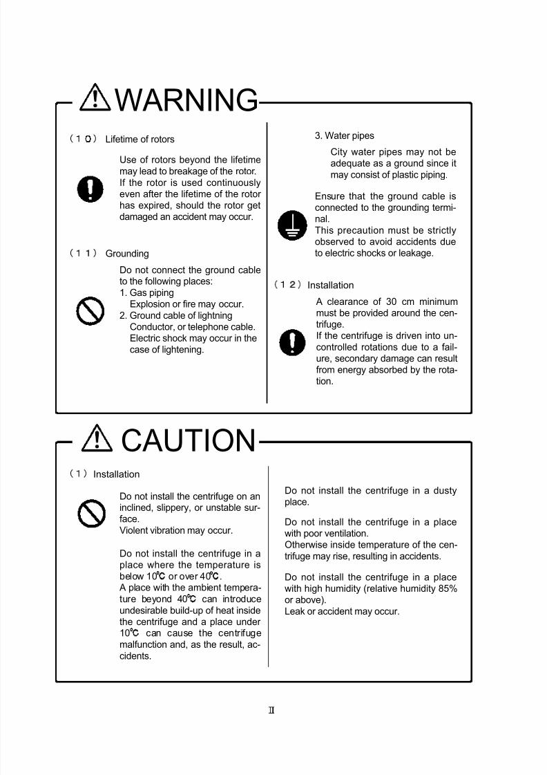
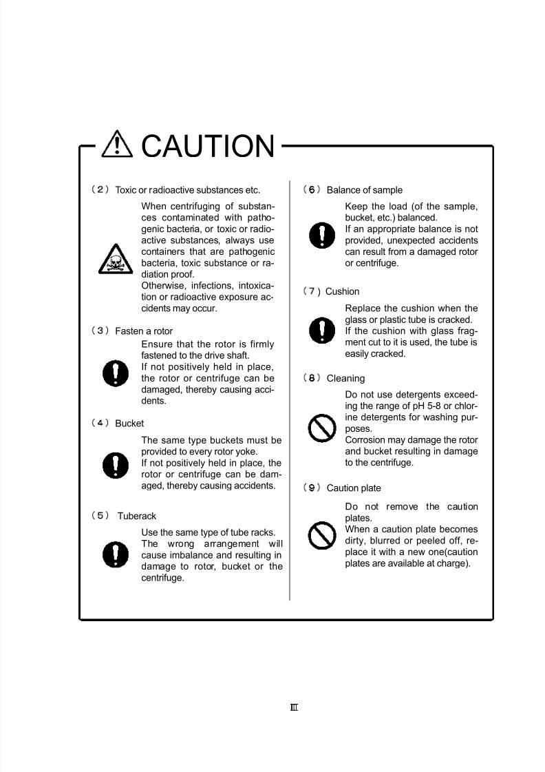
CAUTION
Fasten a rotor
Toxic or radioactive substances etc.
Bucket
Tuberack
) Cushion
Cleaning
Caution plate
When centrifuging of substan-ces contaminated with patho-
genic bacteria, or toxic or radio-active substances, always usecontainers that are pathogenic
bacteria, toxic substance or ra-
diation proof.Otherwise, infections, intoxica-tion or radioactive exposure ac-
cidents may occur.
Do not use detergents exceed-
ing the range of pH 5-8 or chlor-ine detergents for washing pur-
poses.Corrosion may damage the rotor and bucket resulting in damageto the centrifuge.
Replace the cushion when the
glass or plastic tube is cracked.If the cushion with glass frag-ment cut to it is used, the tube is
easily cracked.
Keep the load (of the sample,bucket, etc.) balanced.
If an appropriate balance is not
provided, unexpected accidentscan result from a damaged rotor or centrifuge.
Use the same type of tube racks.
The wrong arrangement willcause imbalance and resulting indamage to rotor, bucket or the
centrifuge.
Ensure that the rotor is firmlyfastened to the drive shaft.
If not positively held in place,
the rotor or centrifuge can bedamaged, thereby causing acci-
dents.
The same type buckets must beprovided to every rotor yoke.
If not positively held in place, therotor or centrifuge can be dam-aged, thereby causing accidents.
Do not remove the caution
plates.When a caution plate becomes
dirty, blurred or peeled off, re-place it with a new one(caution
plates are available at charge).
Balance of sample
7/25/2019 Kubota 2420
http://slidepdf.com/reader/full/kubota-2420 9/70
Ⅳ
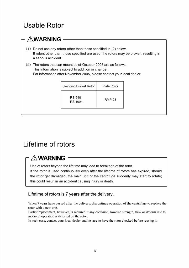
Use of rotors beyond the lifetime may lead to breakage of the rotor.
If the rotor is used continuously even after the lifetime of rotors has expired, should
the rotor get damaged, the main unit of the centrifuge suddenly may start to rotate;
this could result in an accident causing injury or death.
WARNING
Usable Rotor
Lifetime of rotors
Lifetime of rotors is 7 years after the delivery.
When 7 years have passed after the delivery, discontinue operation of the centrifuge to replace the
rotor with a new one.
Earlier replacement, however, is required if any corrosion, lowered strength, flaw or deform due to
incorrect operation is detected on the rotor.
In such case, contact your local dealer and be sure to have the rotor checked before reusing it.
WARNING
(1)Do not use any rotors other than those specified in (2) below.
If rotors other than those specified are used, the rotors may be broken, resulting in
a serious accident.
(2)The rotors that can mount as of October 2005 are as follows:
This information is subject to addition or change.
For information after November 2005, please contact your local dealer.
Swinging Bucket Rotor Plate Rotor
RS-240
RS-1004RMP-23

7/25/2019 Kubota 2420
http://slidepdf.com/reader/full/kubota-2420 10/70
Stop the use of the rotor immediately when it is used beyond the number of
times allowed for autoclaving. Otherwise, the rotor may deteriorate by the heat
generated by autoclaving, resulting in deformation or destruction.
Should the rotor get damaged, the main unit of the centrifuge suddenly may
start to rotate; this could result in an accident causing injury or death.
WARNING
Ⅴ
Number of times allowed for autoclaving of rotor
The number of times allowed for autoclaving of each rotor should be deemed as follows.
When the following conditions have been met, discontinue operation of the centrifuge to
replace the rotor with a new part.
Earlier replacement, however, is required if any corrosion, lowered strength, flaw or deform
due to wrong operation is detected on the rotor. In such case, contact your local dealer and
be sure to have the rotor checked before reusing it.
[1]Number of times allowed for autoclaving and temperature of rotor
[2]Recording autoclave
After each autoclave process, be sure to record the following (1)to (3)to control how
many times the autoclave is executed.
(1)Date
(2)Temperature of autoclave
(3)Time of autoclave
You can take advantage of using the “ Autoclave record table”attached to
the rotor instruction manual.
Rotor Temperature of autoclaveNumber of times
allowed for autoclaving
RMP-23 121℃ 50 times
RS-1004 121℃ 100 times
7/25/2019 Kubota 2420
http://slidepdf.com/reader/full/kubota-2420 11/70
S T AR T
S T O P
T IM E
m i n
s e c
S P E E D
10 0 r p m
10 0 g
M E M O R Y
1 2 3
AC C D E C F U N C T I O N
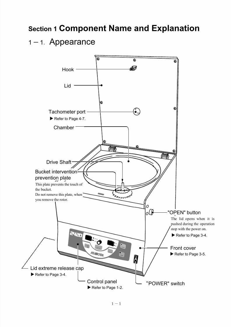
1-1
“POWER" switch
Drive Shaft
Control panel
Chamber
Front cover
Hook
Refer to Page 1-2.
Refer to Page 3-5.
Refer to Page 3-4.
The lid opens when it is
pushed during the operation
stop with the power on.
Lid
Tachometer port
Refer to Page 4-7.
"OPEN" button
Refer to Page 3-4.
Lid extreme release cap
Bucket interventionprevention plate
This plate prevents the touch of
the bucket.
Do not remove this plate, when
you remove the rotor.
Section 1 Component Name and Explanation
1-1. Appearance
7/25/2019 Kubota 2420
http://slidepdf.com/reader/full/kubota-2420 12/70
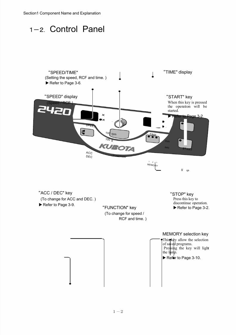
1-2
1-2.Control Panel
Section1 Component Name and Explanation
S T AR T
S T O P
T I M E
m i n
se c
S P E E D
10 0 r p m
10 0 g
M E M O R Y
1 2 3
AC C D E C
F U N C T IO N
When this key is pressedthe operation will bestarted.
“START" key
“TIME" display
“STOP" keyPress this key todiscontinue operation.
“ ACC / DEC" key
“FUNCTION" key
This key allow the selectionof saved programs.Pressing the key will light
the lamp.
MEMORY selection key
“SPEED" display
“SPEED/TIME"
Refer to Page 3-10.
Refer to Page 3-2.
(Setting the speed, RCF and time. )
Refer to Page 3-9.Refer to Page 3-2.
(To change for ACC and DEC. )
Refer to Page 3-6.
(To change for speed /
RCF and time. )
(Speed / RCF )
7/25/2019 Kubota 2420
http://slidepdf.com/reader/full/kubota-2420 13/70
2-1
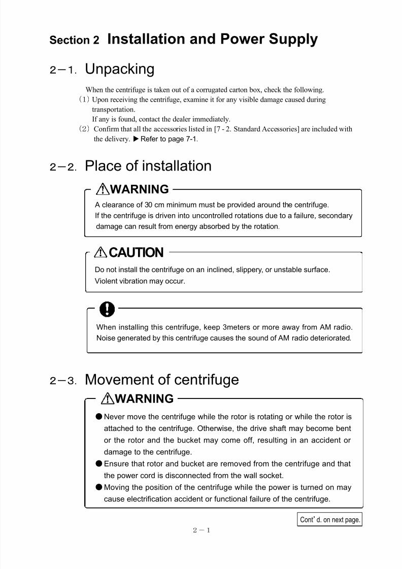
●Never move the centrifuge while the rotor is rotating or while the rotor is
attached to the centrifuge. Otherwise, the drive shaft may become bent
or the rotor and the bucket may come off, resulting in an accident or
damage to the centrifuge.
●Ensure that rotor and bucket are removed from the centrifuge and that
the power cord is disconnected from the wall socket.
●Moving the position of the centrifuge while the power is turned on may
cause electrification accident or functional failure of the centrifuge.
WARNING
When installing this centrifuge, keep 3meters or more away from AM radio.
Noise generated by this centrifuge causes the sound of AM radio deteriorated.
A clearance of 30 cm minimum must be provided around the centrifuge.
If the centrifuge is driven into uncontrolled rotations due to a failure, secondary
damage can result from energy absorbed by the rotation.
WARNING
Do not install the centrifuge on an inclined, slippery, or unstable surface.
Violent vibration may occur.
CAUTION
Cont’d. on next page.
Section 2 Installation and Power Supply
2-1.Unpacking
When the centrifuge is taken out of a corrugated carton box, check the following.
(1)Upon receiving the centrifuge, examine it for any visible damage caused duringtransportation.
If any is found, contact the dealer immediately.
(2)Confirm that all the accessories listed in [7 - 2. Standard Accessories] are included with
the delivery.Refer to page 7-1.
2-2.Place of installation
2-3.Movement of centrifuge
7/25/2019 Kubota 2420
http://slidepdf.com/reader/full/kubota-2420 14/70
2-2
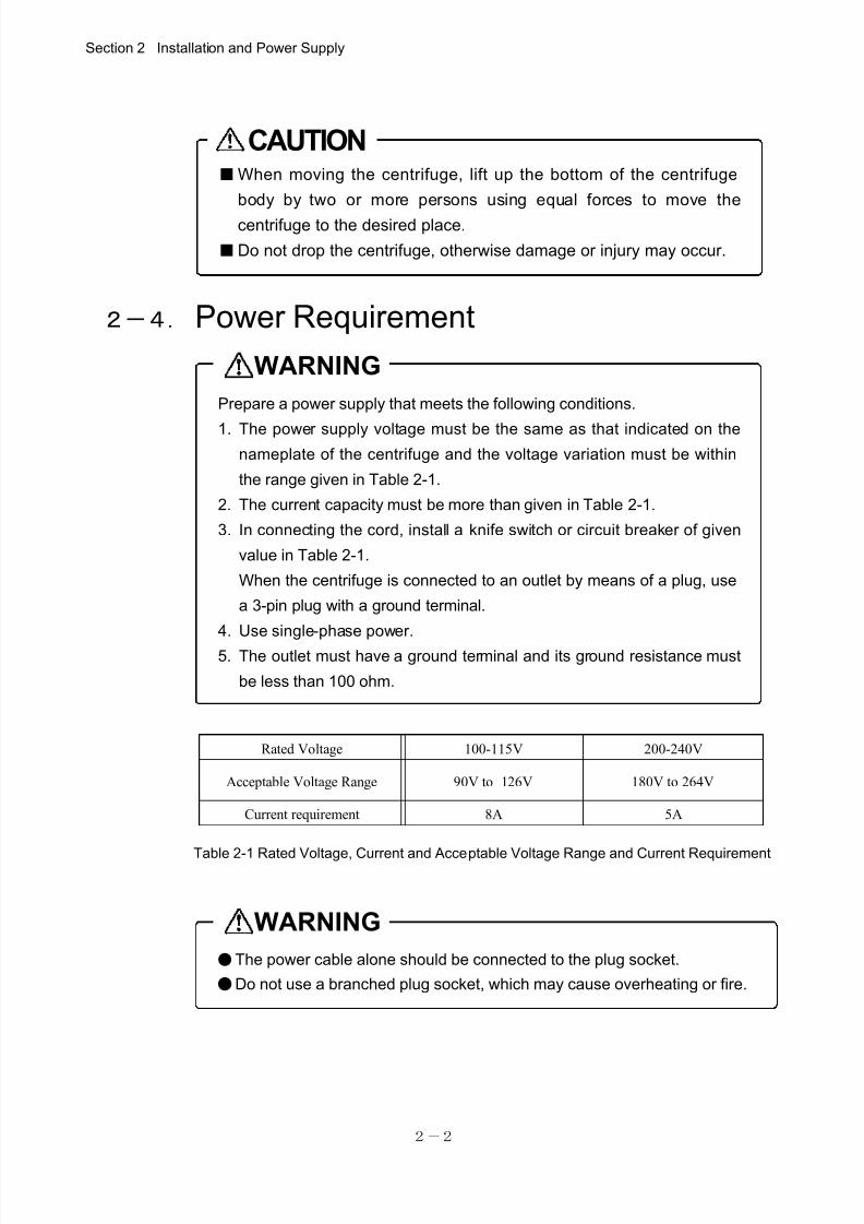
■When moving the centrifuge, lift up the bottom of the centrifuge
body by two or more persons using equal forces to move the
centrifuge to the desired place.
■Do not drop the centrifuge, otherwise damage or injury may occur.
CAUTION
Prepare a power supply that meets the following conditions.
1. The power supply voltage must be the same as that indicated on the
nameplate of the centrifuge and the voltage variation must be within
the range given in Table 2-1.
2. The current capacity must be more than given in Table 2-1.
3. In connecting the cord, install a knife switch or circuit breaker of given
value in Table 2-1.
When the centrifuge is connected to an outlet by means of a plug, use
a 3-pin plug with a ground terminal.
4. Use single-phase power.
5. The outlet must have a ground terminal and its ground resistance must
be less than 100 ohm.
Table 2-1 Rated Voltage, Current and Acceptable Voltage Range and Current Requirement
WARNING
●The power cable alone should be connected to the plug socket.
●Do not use a branched plug socket, which may cause overheating or fire.
WARNING
Rated Voltage 100-115V 200-240V
Acceptable Voltage Range 90V to 126V 180V to 264V
Current requirement 8A 5A
2-4. Power Requirement
Section 2 Installation and Power Supply
7/25/2019 Kubota 2420
http://slidepdf.com/reader/full/kubota-2420 15/70
2-3
Power plug
Inlet
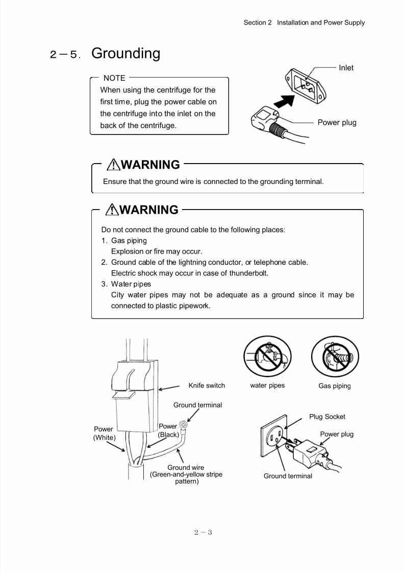
When using the centrifuge for the
first time, plug the power cable on
the centrifuge into the inlet on the
back of the centrifuge.
NOTE
Ensure that the ground wire is connected to the grounding terminal.
WARNING
Do not connect the ground cable to the following places:
1. Gas piping
Explosion or fire may occur.
2. Ground cable of the lightning conductor, or telephone cable.
Electric shock may occur in case of thunderbolt.
3. Water pipes
City water pipes may not be adequate as a ground since it may be
connected to plastic pipework.
WARNING
2-5. Grounding
Section 2 Installation and Power Supply
Plug Socket
Power plug
Ground terminal
Ground wire(Green-and-yellow stripe
pattern)
Ground terminal
Knife switch
Power
(White)
Power
(Black)
water pipes Gas piping
7/25/2019 Kubota 2420
http://slidepdf.com/reader/full/kubota-2420 16/70
3-1
If the lid is not closed properly the
centrifuge is not able to start.
Make sure the lid is closed firmly.
NOTE
Install the rotor after checking if the
"Bucket intervention prevention plate" is
installed on the drive shaft.
Refer to page 1-1.
NOTE
Press the "SPEED/TIME" knob to check the "centrifugal force" of the set
speed or "speed" of the set centrifugal force.
NOTE
When using this centrifuge, observe the contents of the Section "GeneralNotes" being described in the front part of this document and the
precautions given in respective sections.
Cont’d. on next page.
Section 3 Operation
3-1.Cautions of Operation
3-2.Operation
Operation 1. Turn on the "POWER" switch.
Operation 2 .After the "STOP" lamp on the control panel lights, press the "OPEN" button.
Operation 3. Mount the rotor on the drive shaft.
Refer to Section 6.
Operation 4. For swinging bucket rotor ,mount buckets on the rotor.
Operation 5. Place the sample in the rotor or buckets.
Refer to Section 6.
Operation 6. Close the lid firmly.
Operation 7. Proceed to operation 9 when operating with the same setting values as before.
Operation 8. Set the respective parameters.
・Set to required speed.Refer to page 3-6.
・Set to required time.Refer to page 3-8.
・Set braking force during deceleration and acceleration speed with the "ACC/DEC"key.Refer to page 3-9.
●When the memory has been saved, press the selection key.
Refer to page 3-10.
7/25/2019 Kubota 2420
http://slidepdf.com/reader/full/kubota-2420 17/70
3-2
min
sec
min
sec
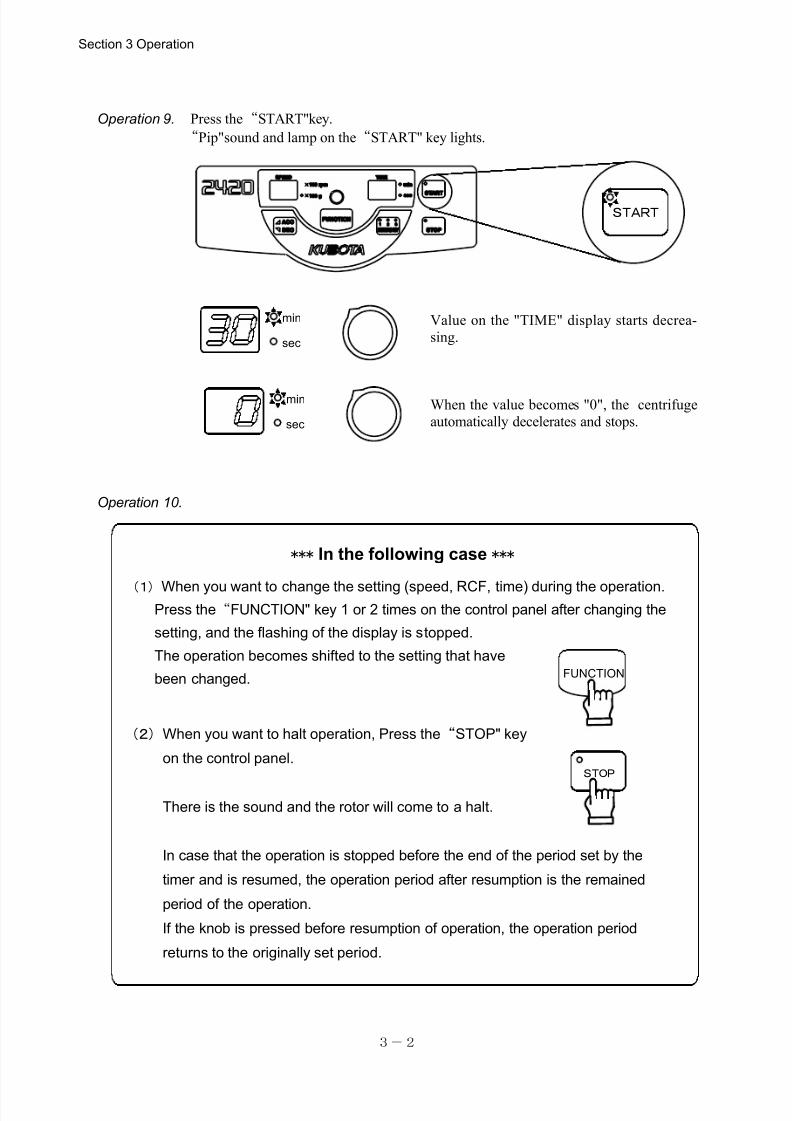
(1)When you want to change the setting (speed, RCF, time) during the operation.Press the“FUNCTION" key 1 or 2 times on the control panel after changing the
setting, and the flashing of the display is stopped.
The operation becomes shifted to the setting that have
been changed.
START
STOP
(2)When you want to halt operation, Press the“STOP" key
on the control panel.
There is the sound and the rotor will come to a halt.
In case that the operation is stopped before the end of the period set by the
timer and is resumed, the operation period after resumption is the remained
period of the operation.
If the knob is pressed before resumption of operation, the operation period
returns to the originally set period.
FUNCTION
Operation 9. Press the“START"key.
“Pip"sound and lamp on the“START" key lights.
Value on the "TIME" display starts decrea-
sing.
When the value becomes "0", the centrifuge
automatically decelerates and stops.
Operation 10.
*** In the following case ***
Section 3 Operation
7/25/2019 Kubota 2420
http://slidepdf.com/reader/full/kubota-2420 18/70
3-3
NOTE
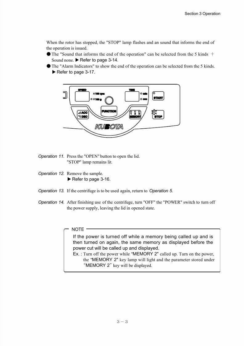
When the rotor has stopped, the "STOP" lamp flashes and an sound that informs the end of
the operation is issued.
●The "Sound that informs the end of the operation" can be selected from the 5 kinds +
Sound none.Refer to page 3-14. ●The "Alarm Indicators" to show the end of the operation can be selected from the 5 kinds.
Refer to page 3-17.
Operation 11. Press the "OPEN" button to open the lid.
"STOP" lamp remains lit.
Operation 12. Remove the sample.
Refer to page 3-16.
Operation 13. If the centrifuge is to be used again, return to Operation 5.
Operation 14. After finishing use of the centrifuge, turn "OFF" the "POWER" switch to turn off
the power supply, leaving the lid in opened state.
If the power is turned off while a memory being called up and is
then turned on again, the same memory as displayed before thepower cut will be called up and displayed.
Ex. : Turn off the power while "MEMORY 2" called up. Turn on the power,
the "MEMORY 2" key lamp will light and the parameter stored under
“MEMORY 2”key will be displayed.
Section 3 Operation
7/25/2019 Kubota 2420
http://slidepdf.com/reader/full/kubota-2420 19/70
3-4
The lid is locked in followingcases and will not open even if
the〈OPEN〉button is pressed.
・ When the rotor is spinning.
・ When there is a power failure
or the power is turned off.
Do not open the lid while the rotor is spinning.
When a power failure occurs during operation of the centrifuge, the rotor
will naturally decelerate to stop its rotation. If the lid is unlocked forcibly
before the rotor stops, the person can be entangled in the rotor, resulting
in a serious injury or death.
WARNING
S T AR T
S T O P
T IM E
m in
s e c
S P E E D
10 0 r p m
10 0 g
M E M O R Y
12
3
AC C D E C F U N C T I O N
“OPEN”button
Open
NOTE
3-3.Opening and Closing the lid
[1]Turning on the power and opening the lid
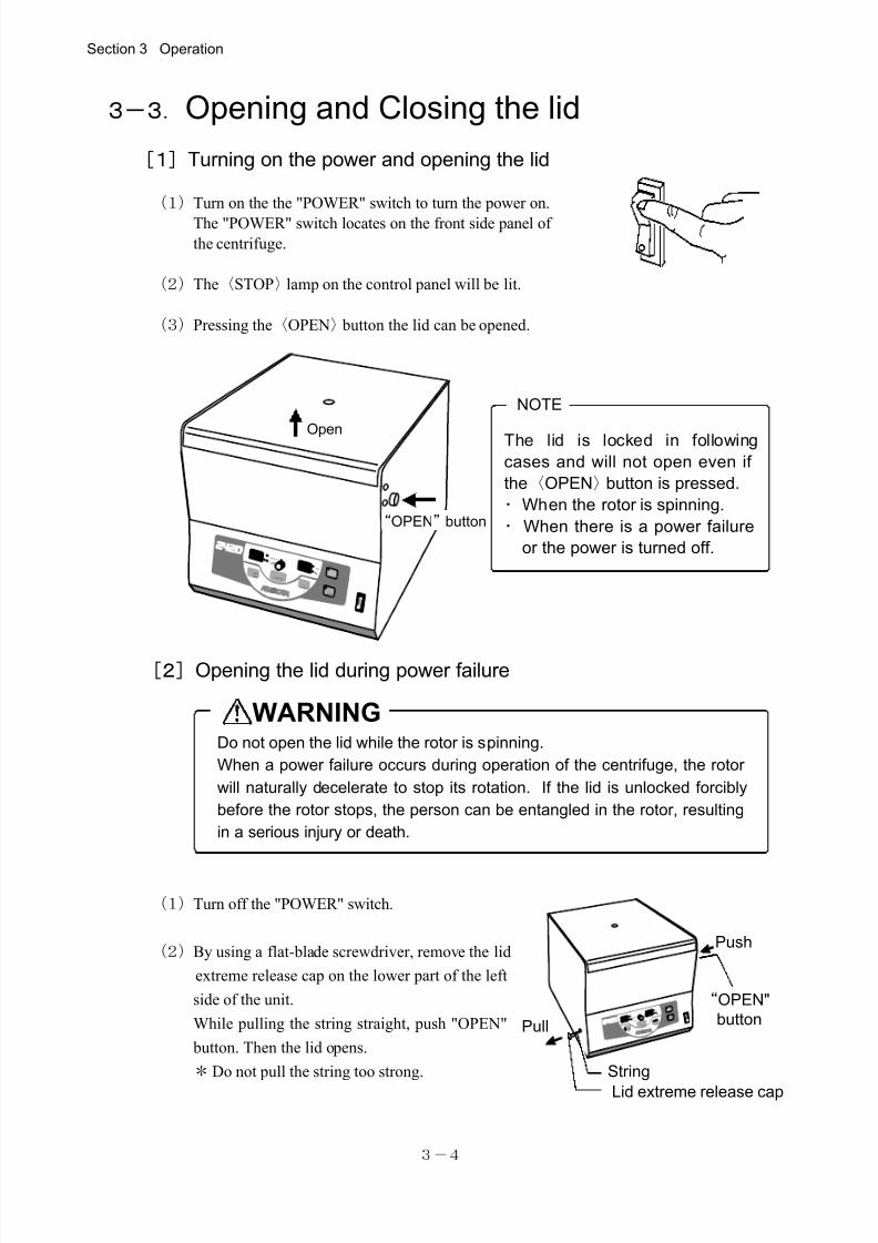
(1)Turn on the the "POWER" switch to turn the power on.
The "POWER" switch locates on the front side panel of
the centrifuge.
(2)The〈STOP〉lamp on the control panel will be lit.
(3)Pressing the〈OPEN〉 button the lid can be opened.
[2]Opening the lid during power failure
(1)Turn off the "POWER" switch.
(2)By using a flat-blade screwdriver, remove the lid
extreme release cap on the lower part of the left
side of the unit.
While pulling the string straight, push "OPEN"
button. Then the lid opens.
*Do not pull the string too strong.
Section 3 Operation
String
S T A R T
ST O P
T IM E
S P E E D
FU N C TI O N
mi n
se c
1 00 r p m
1 0 0 g
M E M O R Y
1 2
3
A CC
D E C
“OPEN"
button
Push
Pull
Lid extreme release cap
7/25/2019 Kubota 2420
http://slidepdf.com/reader/full/kubota-2420 20/70
3-5
The lid can be closed even
when there is a power failure
or the power is turned off .
NOTE
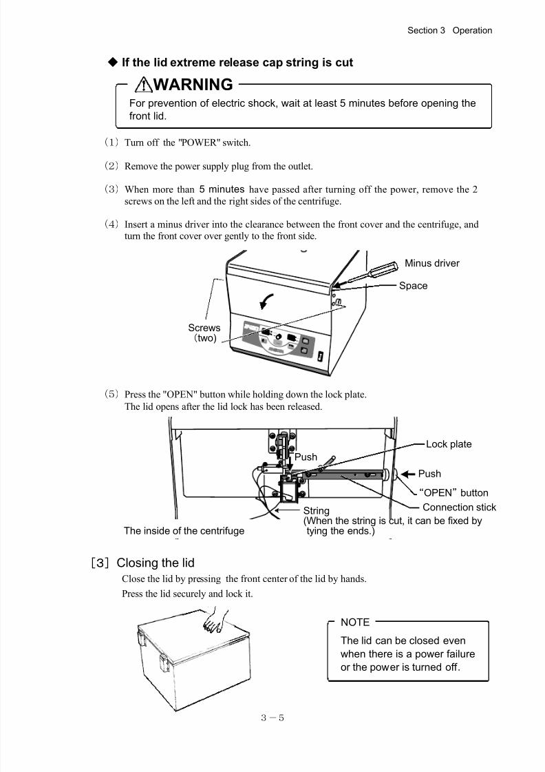
For prevention of electric shock, wait at least 5 minutes before opening the
front lid.
◆ If the lid extreme release cap string is cut
WARNING
(1)Turn off the "POWER" switch.
(2)Remove the power supply plug from the outlet.
(3)When more than 5 minutes have passed after turning off the power, remove the 2
screws on the left and the right sides of the centrifuge.
(4)Insert a minus driver into the clearance between the front cover and the centrifuge, andturn the front cover over gently to the front side.
(5)Press the "OPEN" button while holding down the lock plate.
The lid opens after the lid lock has been released.
[3]Closing the lid
Close the lid by pressing the front center of the lid by hands.
Press the lid securely and lock it.
Section 3 Operation
S T AR T
S TO P
T IM E
m i n
s e c
S P E E D
1 0 0 rp m
1 0 0 g
M E M O R Y
12
3
AC C
D E C F U N C T IO N
Screws(two)
Space
Minus driver
Lock plate
Push
The inside of the centrifuge
String(When the string is cut, it can be fixed bytying the ends.)
Push
“OPEN”button
Connection stick
7/25/2019 Kubota 2420
http://slidepdf.com/reader/full/kubota-2420 21/70
3-6
TIME
SPEED
100rpm×
100 g×FUNCTION
100rpm×
100 g×
100rpm×
100 g×
100rpm×
100 g×
FUNCTIONmin
sec
100rpm×
100 g×
SPEED
SPEED
SPEED
SPEED
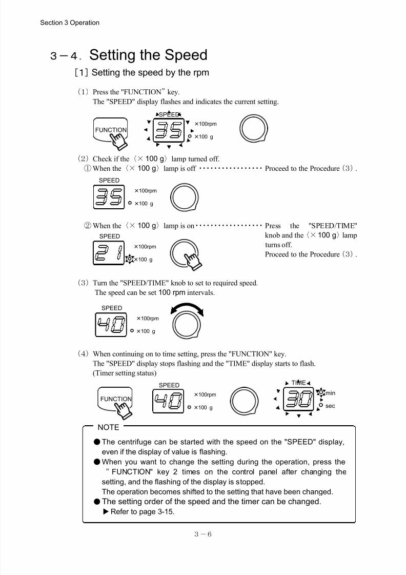
●The centrifuge can be started with the speed on the "SPEED" display,
even if the display of value is flashing.
●When you want to change the setting during the operation, press the
“ FUNCTION" key 2 times on the control panel after changing the
setting, and the flashing of the display is stopped.
The operation becomes shifted to the setting that have been changed.
●The setting order of the speed and the timer can be changed.Refer to page 3-15.
NOTE
3-4.Setting the Speed [1]Setting the speed by the rpm
(1)Press the "FUNCTION”key.
The "SPEED" display flashes and indicates the current setting.
(2)Check if the〈×100 g〉lamp turned off.
①When the〈× 100 g〉lamp is off ・・・・・・・・・・・・・・・・・Proceed to the Procedure(3).
②When the〈× 100 g〉lamp is on・・・・・・・・・・・・・・・・・・Press the "SPEED/TIME"
knob and the〈×100 g〉lamp
turns off.
Proceed to the Procedure(3).
(3)Turn the "SPEED/TIME" knob to set to required speed.
The speed can be set 100 rpm intervals.
(4)When continuing on to time setting, press the "FUNCTION" key.
The "SPEED" display stops flashing and the "TIME" display starts to flash.
(Timer setting status)
Section 3 Operation
7/25/2019 Kubota 2420
http://slidepdf.com/reader/full/kubota-2420 22/70
3-7
TIME
100rpm×
100 g×FUNCTION
100rpm×
100 g×
100rpm×
100 g×
100rpm×100 g×
FUNCTIONmin
sec
100rpm×
100 g×
SPEED
SPEED
SPEED
SPEED
SPEED
NOTE
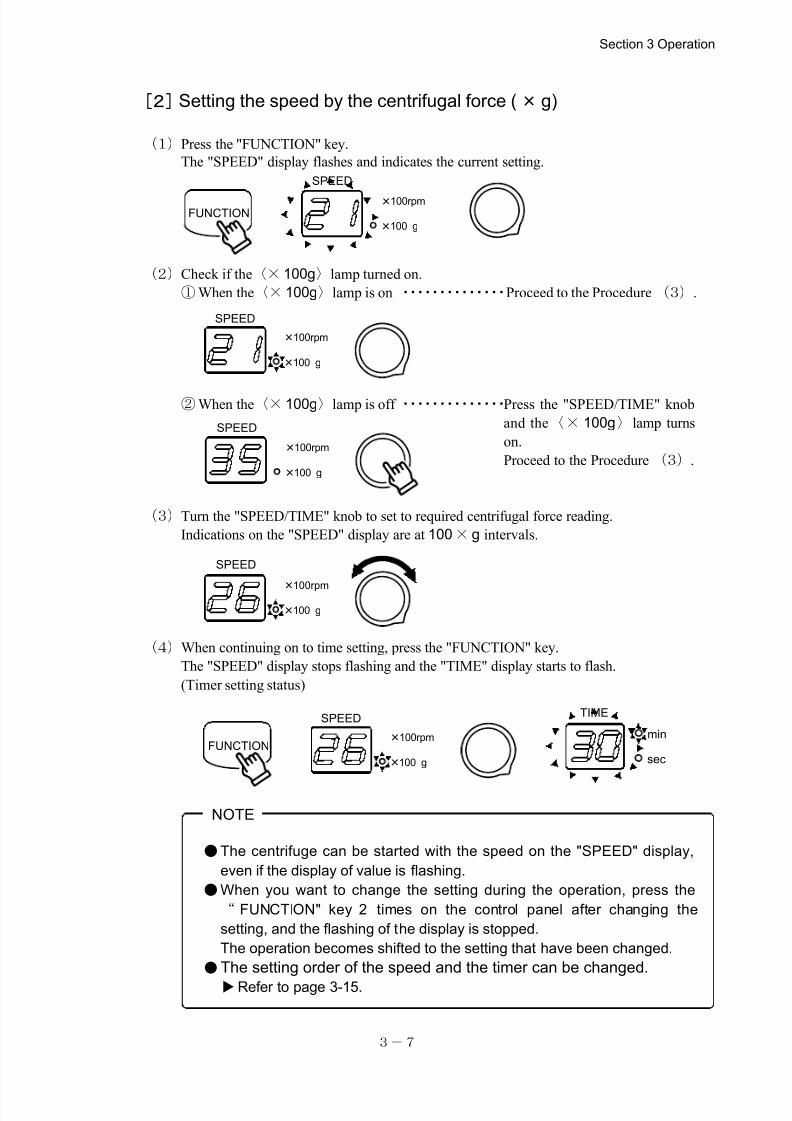
●The centrifuge can be started with the speed on the "SPEED" display,
even if the display of value is flashing.
●When you want to change the setting during the operation, press the
“ FUNCTION" key 2 times on the control panel after changing the
setting, and the flashing of the display is stopped.
The operation becomes shifted to the setting that have been changed.
●The setting order of the speed and the timer can be changed.
Refer to page 3-15.
[2]Setting the speed by the centrifugal force (×g)
(1)Press the "FUNCTION" key.
The "SPEED" display flashes and indicates the current setting.
(2)Check if the〈×100g〉lamp turned on.
①When the〈×100g〉lamp is on ・・・・・・・・・・・・・・Proceed to the Procedure (3).
②When the〈×100g〉lamp is off ・・・・・・・・・・・・・・Press the "SPEED/TIME" knob
and the〈× 100g〉lamp turns
on.
Proceed to the Procedure (3).
(3)Turn the "SPEED/TIME" knob to set to required centrifugal force reading.
Indications on the "SPEED" display are at 100×g intervals.
(4)When continuing on to time setting, press the "FUNCTION" key.
The "SPEED" display stops flashing and the "TIME" display starts to flash.
(Timer setting status)
Section 3 Operation
7/25/2019 Kubota 2420
http://slidepdf.com/reader/full/kubota-2420 23/70
3-8
min
sec
min
sec
FUNCTION
NOTE
● In case that the operation is stopped before the end of the period set by thetimer and is resumed, the operation period after resumption is the remained
period of the operation.
If the "SPEED/TIME" knob is pressed before resumption of operation, the
operation period returns to the originally set period.
●The centrifuge can be started at the time when the setting value is flashing at
"TIME" display.
●When you want to change the setting during the operation, press the
“ FUNCTION" key on the control panel after changing the setting, and the
flashing of the display is stopped.
The operation becomes shifted to the setting that have been changed.
●The speed and the timer can be set in this sequence or vice versa. As for the change of the setting, please refer to page 3-15.
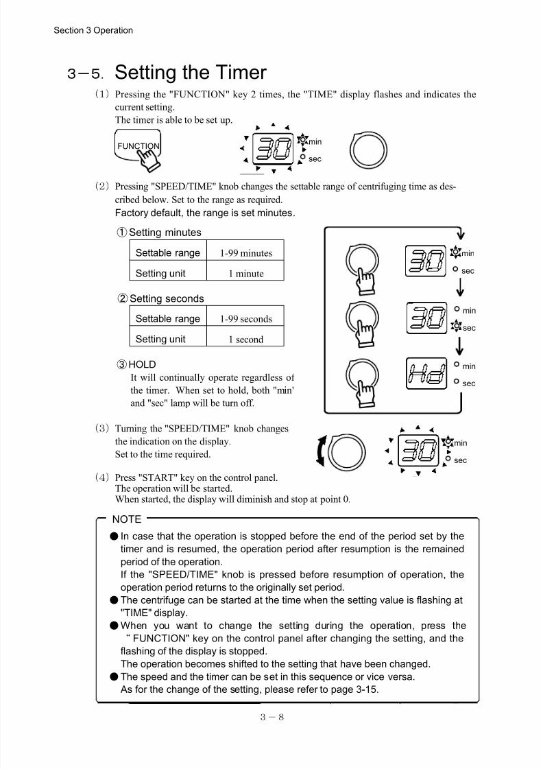
3-5.Setting the Timer (1)Pressing the "FUNCTION" key 2 times, the "TIME" display flashes and indicates the
current setting.
The timer is able to be set up.
(2)Pressing "SPEED/TIME" knob changes the settable range of centrifuging time as des-
cribed below. Set to the range as required.
Factory default,the range is set minutes.
③HOLD
It will continually operate regardless of
the timer. When set to hold, both "min"
and "sec" lamp will be turn off.
(3)Turning the "SPEED/TIME" knob changes
the indication on the display.
Set to the time required.
(4)Press "START" key on the control panel.The operation will be started.When started, the display will diminish and stop at point 0.
Section 3 Operation
②Setting seconds
①Setting minutes
Settable range 1-99 minutes
Setting unit 1 minute
Settable range 1-99 seconds
Setting unit 1 second
min
sec
min
sec
min
sec
7/25/2019 Kubota 2420
http://slidepdf.com/reader/full/kubota-2420 24/70
3-9
ACC
DEC
ACC
DEC
ACC
DEC
ACC
DEC
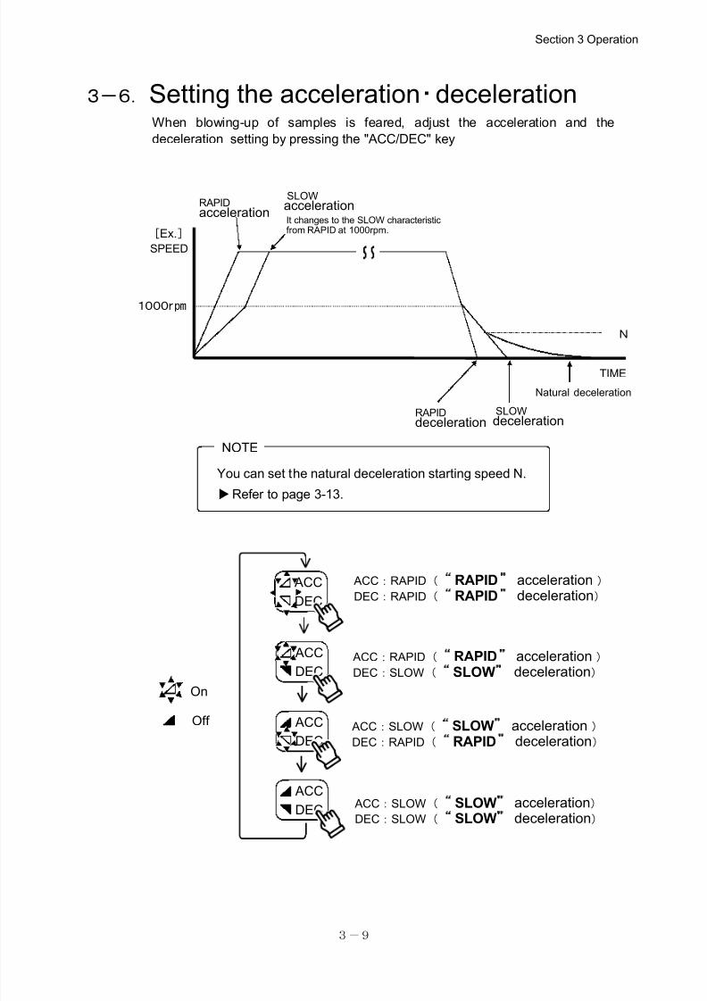
ACC:RAPID( RAPID acceleration )DEC:RAPID( RAPID deceleration)
ACC:RAPID( RAPID acceleration )DEC:SLOW( SLOW deceleration)
ACC:SLOW( SLOW acceleration )DEC:RAPID( RAPID deceleration)
ACC:SLOW( SLOW acceleration)DEC:SLOW( SLOW deceleration)
On
Off
It changes to the SLOW characteristicfrom RAPID at 1000rpm.
Natural deceleration
1000rpm
N
[Ex.]
SPEED
RAPIDdeceleration
SLOWaccelerationRAPID
acceleration
SLOWdeceleration
You can set the natural deceleration starting speed N.
Refer to page 3-13.
NOTE
TIME
3-6.Setting the acceleration・decelerationWhen blowing-up of samples is feared, adjust the acceleration and the
deceleration setting by pressing the "ACC/DEC" key
Section 3 Operation
7/25/2019 Kubota 2420
http://slidepdf.com/reader/full/kubota-2420 25/70
3-10
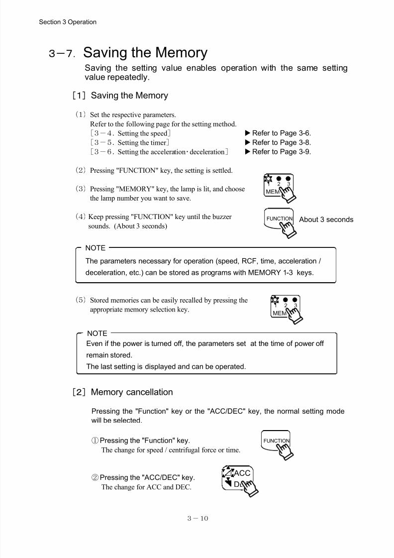
The parameters necessary for operation (speed, RCF, time, acceleration /
deceleration, etc.) can be stored as programs with MEMORY 1-3 keys.
NOTE
MEMORY
1 2 3
FUNCTION About 3 seconds
MEMORY
1 2 3
FUNCTION
ACC
DEC
Even if the power is turned off, the parameters set at the time of power off
remain stored.
The last setting is displayed and can be operated.
NOTE
3-7.Saving the MemorySaving the setting value enables operation with the same settingvalue repeatedly.
[1]Saving the Memory
(1)Set the respective parameters.
Refer to the following page for the setting method.
[3-4.Setting the speed] Refer to Page 3-6.
[3-5.Setting the timer ] Refer to Page 3-8.
[3-6.Setting the acceleration・deceleration] Refer to Page 3-9.
(2)Pressing "FUNCTION" key, the setting is settled.
(3)Pressing "MEMORY" key, the lamp is lit, and choose
the lamp number you want to save.
(4)Keep pressing "FUNCTION" key until the buzzer
sounds. (About 3 seconds)
(5)Stored memories can be easily recalled by pressing the
appropriate memory selection key.
[2]Memory cancellation
Pressing the "Function" key or the "ACC/DEC" key, the normal setting mode
will be selected.
①Pressing the "Function" key.
The change for speed / centrifugal force or time.
②Pressing the "ACC/DEC" key.
The change for ACC and DEC.
Section 3 Operation
7/25/2019 Kubota 2420
http://slidepdf.com/reader/full/kubota-2420 26/70
3-11
FUNCTION
100rpm×
100 g×
min
sec
SPEED TIME
100rpm×
100 g×
min
sec
SPEED TIME
100rpm×
100 g×
min
sec
SPEED TIME
100rpm×
100 g×
min
sec
SPEED TIME
100rpm×
100 g×
min
sec
SPEED TIME
100rpm×
100 g×
min
sec
SPEED TIME
100rpm×
100 g×
min
sec
SPEED TIME
NOTE
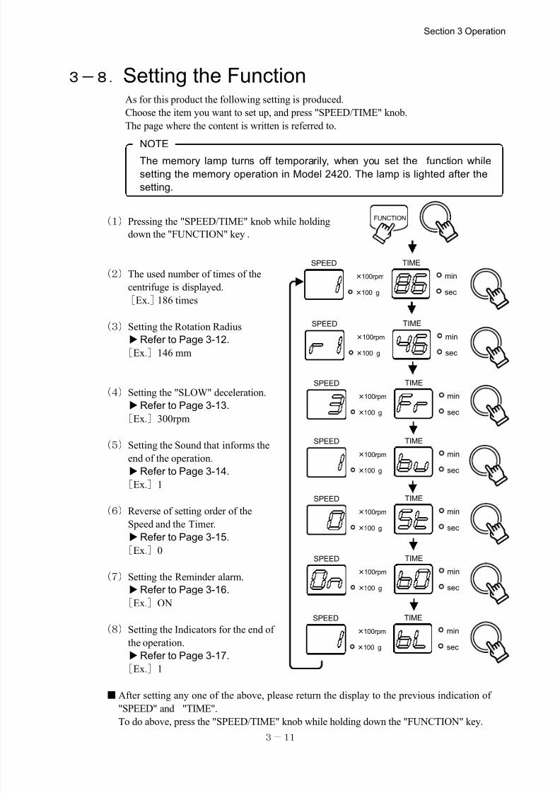
The memory lamp turns off temporarily, when you set the function while
setting the memory operation in Model 2420. The lamp is lighted after the
setting.
3-8.Setting the FunctionAs for this product the following setting is produced.
Choose the item you want to set up, and press "SPEED/TIME" knob.
The page where the content is written is referred to.
(1)Pressing the "SPEED/TIME" knob while holding
down the "FUNCTION" key .
(2)The used number of times of thecentrifuge is displayed.
[Ex.]186 times
(3)Setting the Rotation Radius
Refer to Page 3-12.
[Ex.]146 mm
(4)Setting the "SLOW" deceleration.
Refer to Page 3-13.
[Ex.]300rpm
(5)Setting the Sound that informs the
end of the operation.
Refer to Page 3-14.
[Ex.]1
(6)Reverse of setting order of the
Speed and the Timer.
Refer to Page 3-15.
[Ex.
]0
(7)Setting the Reminder alarm.
Refer to Page 3-16.
[Ex.]ON
(8)Setting the Indicators for the end of
the operation.
Refer to Page 3-17.
[Ex.]1
■After setting any one of the above, please return the display to the previous indication of"SPEED" and "TIME".
To do above, press the "SPEED/TIME" knob while holding down the "FUNCTION" key.
Section 3 Operation
7/25/2019 Kubota 2420
http://slidepdf.com/reader/full/kubota-2420 27/70
3-12
FUNCTION
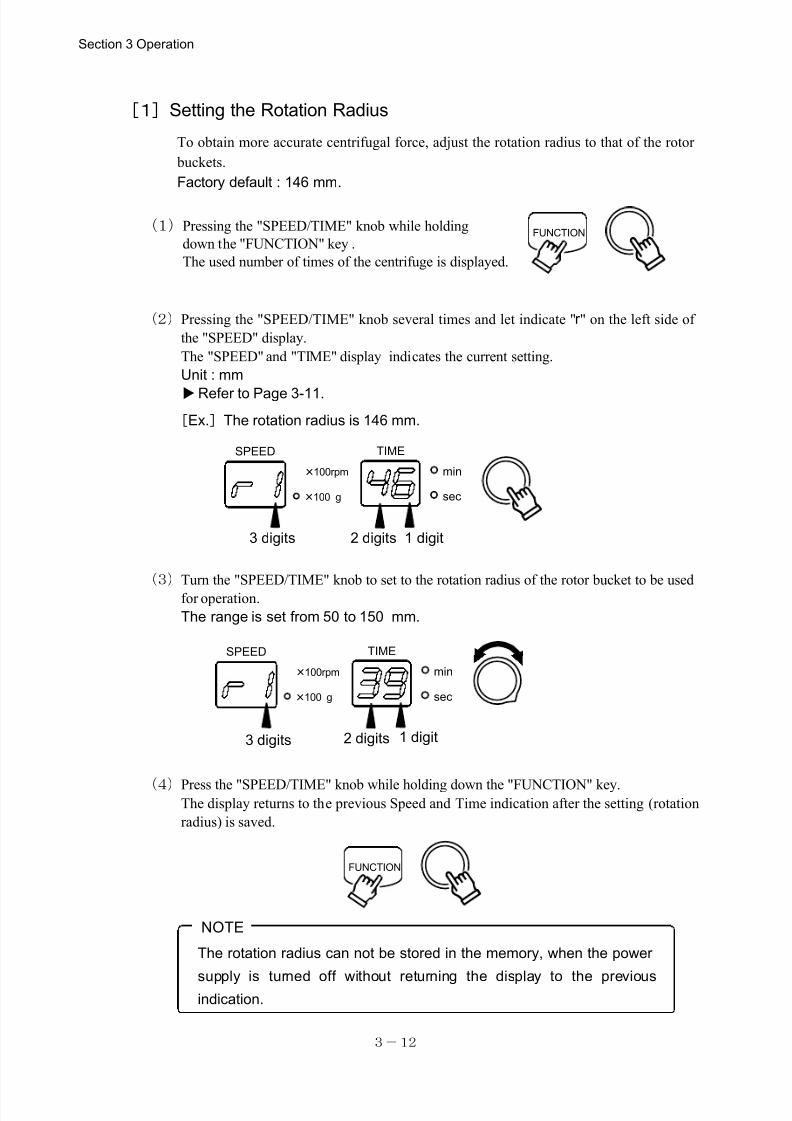
The rotation radius can not be stored in the memory, when the power
supply is turned off without returning the display to the previousindication.
NOTE
100rpm×
100 g×
min
sec
SPEED TIME
100rpm×
100 g×
min
sec
SPEED TIME
3 digits 2 digits 1 digit
[Ex.]The rotation radius is 146 mm.
3 digits 2 digits 1 digit
FUNCTION
[1]Setting the Rotation Radius
To obtain more accurate centrifugal force, adjust the rotation radius to that of the rotor
buckets.
Factory default : 146 mm.
(1)Pressing the "SPEED/TIME" knob while holding
down the "FUNCTION" key .
The used number of times of the centrifuge is displayed.
(2)Pressing the "SPEED/TIME" knob several times and let indicate "r " on the left side of
the "SPEED" display.
The "SPEED" and "TIME" display indicates the current setting.
Unit : mm
Refer to Page 3-11.
(3)Turn the "SPEED/TIME" knob to set to the rotation radius of the rotor bucket to be used
for operation.
The range is set from 50 to 150 mm.
(4)Press the "SPEED/TIME" knob while holding down the "FUNCTION" key.The display returns to the previous Speed and Time indication after the setting (rotation
radius) is saved.
Section 3 Operation
7/25/2019 Kubota 2420
http://slidepdf.com/reader/full/kubota-2420 28/70
3-13
100rpm×
100 g×
min
sec
SPEED TIME
100rpm×
100 g×
min
sec
SPEED TIME
FUNCTION
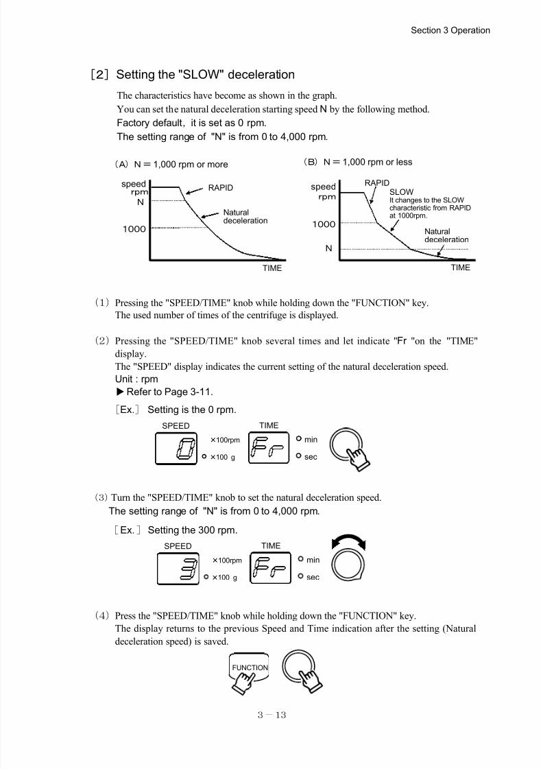
[2]Setting the "SLOW" deceleration
The characteristics have become as shown in the graph.
You can set the natural deceleration starting speed N by the following method.
Factory default, it is set as 0 rpm.
The setting range of "N" is from 0 to 4,000 rpm.
(1)Pressing the "SPEED/TIME" knob while holding down the "FUNCTION" key.
The used number of times of the centrifuge is displayed.
(2)Pressing the "SPEED/TIME" knob several times and let indicate "Fr "on the "TIME"
display.
The "SPEED" display indicates the current setting of the natural deceleration speed.
Unit : rpm
Refer to Page 3-11.
[Ex.] Setting is the 0 rpm.
(3)Turn the "SPEED/TIME" knob to set the natural deceleration speed.
The setting range of "N" is from 0 to 4,000 rpm.
[Ex.]Setting the 300 rpm.
(4)Press the "SPEED/TIME" knob while holding down the "FUNCTION" key.
The display returns to the previous Speed and Time indication after the setting (Natural
deceleration speed) is saved.
Section 3 Operation
N
1000
N
1000
(A)N=1,000 rpm or more (B)N=1,000 rpm or less
rpmrpm
speed
It changes to the SLOWcharacteristic from RAPIDat 1000rpm.
RAPID
Naturaldeceleration
SLOW
TIME TIME
speed RAPID
Naturaldeceleration
7/25/2019 Kubota 2420
http://slidepdf.com/reader/full/kubota-2420 29/70
3-14
100rpm×
100 g×
min
sec
SPEED TIME
100rpm×
100 g×
min
sec
SPEED TIME
FUNCTION
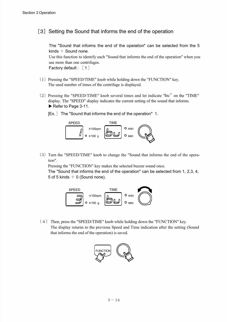
[3]Setting the Sound that informs the end of the operation
The "Sound that informs the end of the operation" can be selected from the 5
kinds + Sound none.
Use this function to identify each "Sound that informs the end of the operation" when youuse more than one centrifuges.
Factory default : [1]
(1)Pressing the "SPEED/TIME" knob while holding down the "FUNCTION" key.
The used number of times of the centrifuge is displayed.
(2)Pressing the "SPEED/TIME" knob several times and let indicate "bu" on the "TIME"
display. The "SPEED" display indicates the current setting of the sound that informs.
Refer to Page 3-11.
[Ex.]The "Sound that informs the end of the operation" 1.
(3)Turn the "SPEED/TIME" knob to change the "Sound that informs the end of the opera-
tion".
Pressing the "FUNCTION" key makes the selected buzzer sound once.
The "Sound that informs the end of the operation" can be selected from 1, 2,3, 4,
5 of 5 kinds + 0 (Sound none).
(4)Then, press the "SPEED/TIME" knob while holding down the "FUNCTION" key.
The display returns to the previous Speed and Time indication after the setting (Sound
that informs the end of the operation) is saved.
Section 3 Operation
7/25/2019 Kubota 2420
http://slidepdf.com/reader/full/kubota-2420 30/70
3-15
100rpm×
100 g×
min
sec
SPEED TIME
100rpm×
100 g×
min
sec
SPEED TIME
FUNCTION
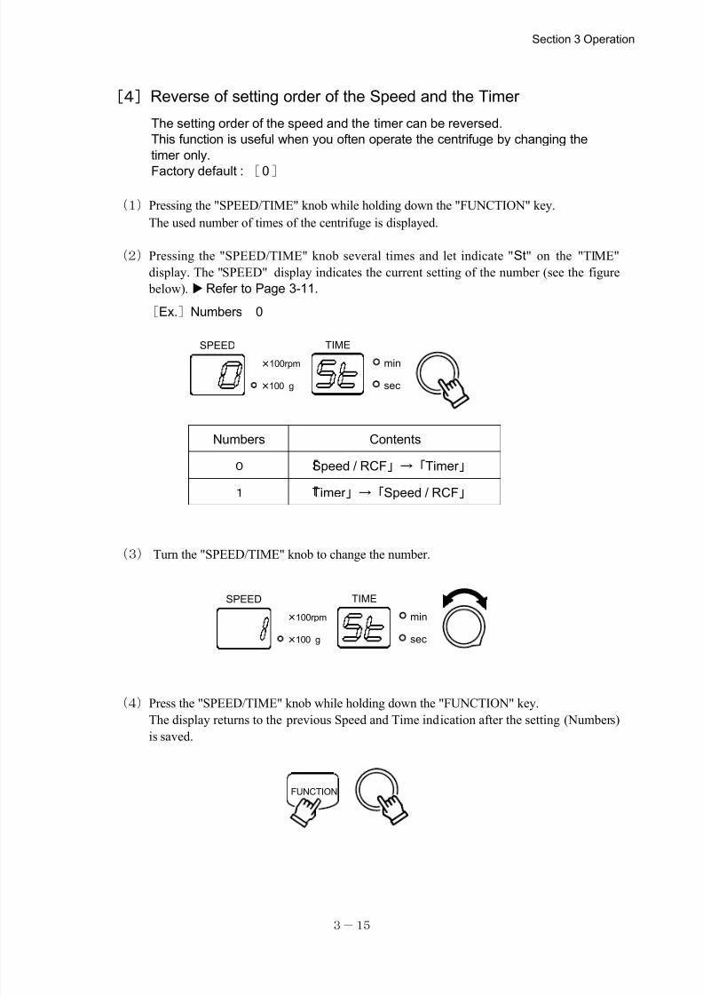
Numbers Contents
0 「Speed / RCF」→「Timer 」
1 「Timer 」→「Speed / RCF」
[4]Reverse of setting order of the Speed and the Timer
The setting order of the speed and the timer can be reversed.
This function is useful when you often operate the centrifuge by changing the
timer only.
Factory default : [0]
(1)Pressing the "SPEED/TIME" knob while holding down the "FUNCTION" key.
The used number of times of the centrifuge is displayed.
(2)Pressing the "SPEED/TIME" knob several times and let indicate "St" on the "TIME"
display. The "SPEED" display indicates the current setting of the number (see the figure
below).Refer to Page 3-11.
[Ex.]Numbers 0
(3) Turn the "SPEED/TIME" knob to change the number.
(4)Press the "SPEED/TIME" knob while holding down the "FUNCTION" key.
The display returns to the previous Speed and Time indication after the setting (Numbers)
is saved.
Section 3 Operation
7/25/2019 Kubota 2420
http://slidepdf.com/reader/full/kubota-2420 31/70
3-16
100rpm×
100 g×
min
sec
SPEED TIME
100rpm×
100 g×
min
sec
SPEED TIME
FUNCTION
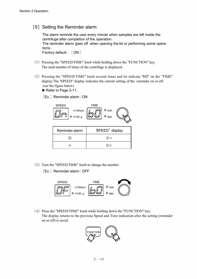
Reminder alarm “SPEED”display.
○
×
[5]Setting the Reminder alarm
The alarm reminds the user every minute when samples are left inside the
centrifuge after completion of the operation.
The reminder alarm goes off when opening the lid or performing some opera-
tions.Factory default : [ON]
(1)Pressing the "SPEED/TIME" knob while holding down the "FUNCTION" key.
The used number of times of the centrifuge is displayed.
(2)Pressing the "SPEED/TIME" knob several times and let indicate "bO" on the "TIME"
display.The "SPEED" display indicates the current setting of the reminder on or off.
(see the figure below)
Refer to Page 3-11.
[Ex.]Reminder alarm : ON
(3)Turn the "SPEED/TIME" knob to change the number.
[Ex.]Reminder alarm : OFF
(4)Press the "SPEED/TIME" knob while holding down the "FUNCTION" key.
The display returns to the previous Speed and Time indication after the setting (reminder
on or off) is saved.
Section 3 Operation
7/25/2019 Kubota 2420
http://slidepdf.com/reader/full/kubota-2420 32/70
3-17
100rpm×
100 g×
min
sec
SPEED TIME
100rpm×
100 g×
min
sec
SPEED TIME
FUNCTION
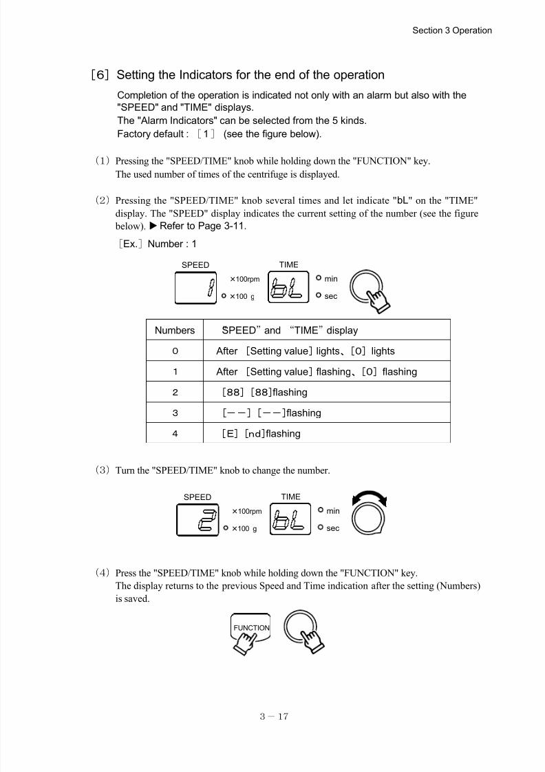
Numbers “SPEED”and “TIME”display
0 After[Setting value]lights、[0]lights
1 After[Setting value]flashing、[0]flashing
2 [88][88]flashing
3 [--][--]flashing
4 [E][nd]flashing
[6]Setting the Indicators for the end of the operation
Completion of the operation is indicated not only with an alarm but also with the
"SPEED" and "TIME" displays.
The "Alarm Indicators" can be selected from the 5 kinds.
Factory default : [1] (see the figure below).
(1)Pressing the "SPEED/TIME" knob while holding down the "FUNCTION" key.
The used number of times of the centrifuge is displayed.
(2)Pressing the "SPEED/TIME" knob several times and let indicate "bL" on the "TIME"
display. The "SPEED" display indicates the current setting of the number (see the figure
below).Refer to Page 3-11.
[Ex.]Number : 1
(3)Turn the "SPEED/TIME" knob to change the number.
(4)Press the "SPEED/TIME" knob while holding down the "FUNCTION" key.
The display returns to the previous Speed and Time indication after the setting (Numbers)
is saved.
Section 3 Operation
7/25/2019 Kubota 2420
http://slidepdf.com/reader/full/kubota-2420 33/70
3-18
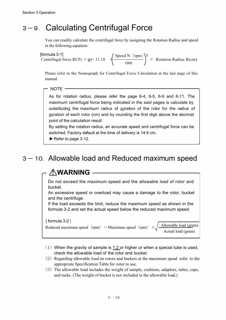
Allowable load (gram)
Actual load (gram)Reduced maximum speed(rpm)=Maximum speed(rpm)×
Do not exceed the maximum speed and the allowable load of rotor and
bucket.
An excessive speed or overload may cause a damage to the rotor, bucket
and the centrifuge.
If the load exceeds the limit, reduce the maximum speed as shown in the
formula 3-2 and set the actual speed below the reduced maximum speed.
[ formula 3-2 ]
As for rotation radius, please refer the page 6-4, 6-5, 6-9 and 6-11. The
maximum centrifugal force being indicated in the said pages is calculate by
substituting the maximum radius of gyration of the rotor for the radius of
gyration of each rotor (cm) and by rounding the first digit above the decimal
point of the calculation result.
By setting the rotation radius, an accurate speed and centrifugal force can be
switched. Factory default at the time of delivery is 14.6 cm.
Refer to page 3-12.
(1)When the gravity of sample is 1.2 or higher or when a special tube is used,
check the allowable load of the rotor and bucket.
(2)Regarding allowable load on rotors and buckets at the maximum speed refer to the
appropriate Specification Table for rotor in use.
(3)The allowable load includes the weight of sample, cushions, adaptors, tubes, caps,
and racks. (The weight of bucket is not included in the allowable load.)
WARNING
NOTE
3-9. Calculating Centrifugal Force
You can readily calculate the centrifugal force by assigning the Rotation Radius and speed
in the following equation:
Please refer to the Nomograph for Centrifugal Force Calculation at the last page of this
manual.
3-10. Allowable load and Reduced maximum speed
Section 3 Operation
Centrifugal force RCF( × g)= 11.18 × Speed N(rpm)1000
2× Rotation Radius R(cm)[formula 3-1]
7/25/2019 Kubota 2420
http://slidepdf.com/reader/full/kubota-2420 34/70
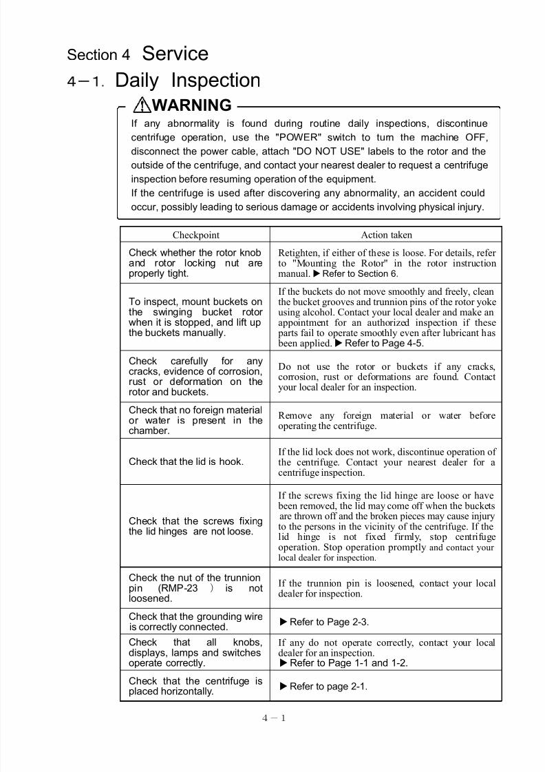
4-1
If any abnormality is found during routine daily inspections, discontinue
centrifuge operation, use the "POWER" switch to turn the machine OFF,
disconnect the power cable, attach "DO NOT USE" labels to the rotor and the
outside of the centrifuge, and contact your nearest dealer to request a centrifuge
inspection before resuming operation of the equipment.
If the centrifuge is used after discovering any abnormality, an accident could
occur, possibly leading to serious damage or accidents involving physical injury.
WARNING
Checkpoint Action taken
Check whether the rotor knoband rotor locking nut areproperly tight.
Retighten, if either of these is loose. For details, referto "Mounting the Rotor" in the rotor instructionmanual.Refer to Section 6.
To inspect, mount buckets on the swinging bucket rotorwhen it is stopped, and lift upthe buckets manually.
If the buckets do not move smoothly and freely, cleanthe bucket grooves and trunnion pins of the rotor yokeusing alcohol. Contact your local dealer and make anappointment for an authorized inspection if these parts fail to operate smoothly even after lubricant has been applied.Refer to Page 4-5.
Check carefully for anycracks, evidence of corrosion, rust or deformation on therotor and buckets.
Do not use the rotor or buckets if any cracks,corrosion, rust or deformations are found. Contactyour local dealer for an inspection.
Check that no foreign material or water is present in thechamber.
Remove any foreign material or water beforeoperating the centrifuge.
Check that the lid is hook.If the lid lock does not work, discontinue operation of the centrifuge. Contact your nearest dealer for acentrifuge inspection.
Check that the screws fixingthe lid hinges are not loose.
If the screws fixing the lid hinge are loose or have been removed, the lid may come off when the buckets are thrown off and the broken pieces may cause injuryto the persons in the vicinity of the centrifuge. If the
lid hinge is not fixed firmly, stop centrifugeoperation. Stop operation promptly and contact yourlocal dealer for inspection.
Check the nut of the trunnionpin (RMP-23 ) is notloosened.
If the trunnion pin is loosened, contact your localdealer for inspection.
Check that the grounding wire is correctly connected.
Refer to Page 2-3.
Check that all knobs,displays, lamps and switchesoperate correctly.
If any do not operate correctly, contact your localdealer for an inspection.Refer to Page 1-1 and 1-2.
Check that the centrifuge isplaced horizontally.
Refer to page 2-1.
Section 4 Service
4-1.Daily Inspection
7/25/2019 Kubota 2420
http://slidepdf.com/reader/full/kubota-2420 35/70
4-2
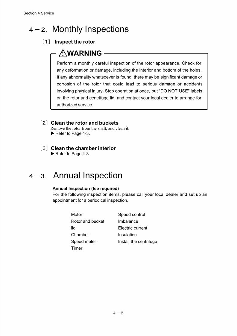
WARNING
Perform a monthly careful inspection of the rotor appearance. Check for
any deformation or damage, including the interior and bottom of the holes.
If any abnormality whatsoever is found, there may be significant damage or
corrosion of the rotor that could lead to serious damage or accidents
involving physical injury. Stop operation at once, put "DO NOT USE" labels
on the rotor and centrifuge lid, and contact your local dealer to arrange for
authorized service.
Motor Speed control
Rotor and bucket Imbalance
lid Electric current
Chamber InsulationSpeed meter Install the centrifuge
Timer
4-2.Monthly Inspections
[1] Inspect the rotor
[2]Clean the rotor and bucketsRemove the rotor from the shaft, and clean it.
Refer to Page 4-3.
[3]Clean the chamber interior Refer to Page 4-3.
4-3. Annual InspectionAnnual Inspection (fee required)
For the following inspection items, please call your local dealer and set up an
appointment for a periodical inspection.
Section 4 Service
7/25/2019 Kubota 2420
http://slidepdf.com/reader/full/kubota-2420 36/70
4-3
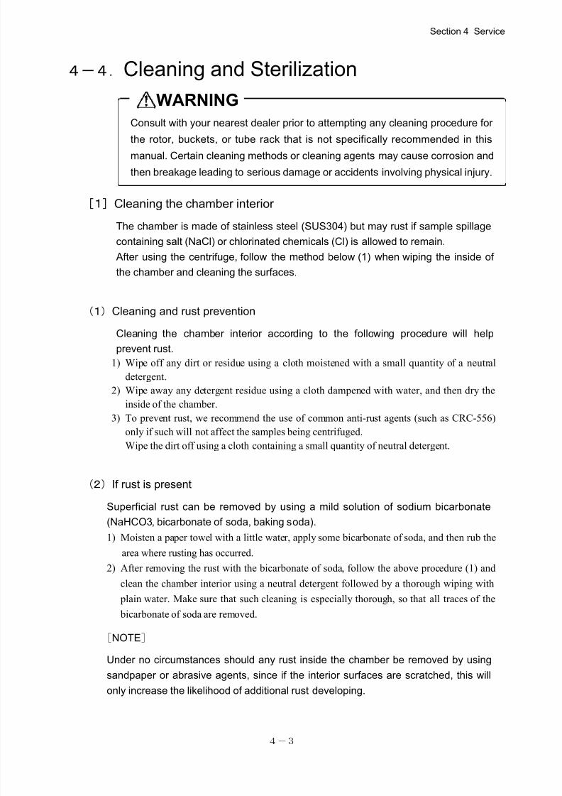
Consult with your nearest dealer prior to attempting any cleaning procedure for
the rotor, buckets, or tube rack that is not specifically recommended in this
manual. Certain cleaning methods or cleaning agents may cause corrosion and
then breakage leading to serious damage or accidents involving physical injury.
WARNING
4-4.Cleaning and Sterilization
[1]Cleaning the chamber interior
The chamber is made of stainless steel (SUS304) but may rust if sample spillage
containing salt (NaCl) or chlorinated chemicals (Cl) is allowed to remain.
After using the centrifuge, follow the method below (1) when wiping the inside of
the chamber and cleaning the surfaces.
(1)Cleaning and rust prevention
Cleaning the chamber interior according to the following procedure will help
prevent rust.
1) Wipe off any dirt or residue using a cloth moistened with a small quantity of a neutral
detergent.
2) Wipe away any detergent residue using a cloth dampened with water, and then dry the
inside of the chamber.
3) To prevent rust, we recommend the use of common anti-rust agents (such as CRC-556)only if such will not affect the samples being centrifuged.
Wipe the dirt off using a cloth containing a small quantity of neutral detergent.
(2)If rust is present
Superficial rust can be removed by using a mild solution of sodium bicarbonate
(NaHCO3, bicarbonate of soda, baking soda).
1) Moisten a paper towel with a little water, apply some bicarbonate of soda, and then rub the
area where rusting has occurred.2) After removing the rust with the bicarbonate of soda, follow the above procedure (1) and
clean the chamber interior using a neutral detergent followed by a thorough wiping with
plain water. Make sure that such cleaning is especially thorough, so that all traces of the
bicarbonate of soda are removed.
[NOTE]
Under no circumstances should any rust inside the chamber be removed by using
sandpaper or abrasive agents, since if the interior surfaces are scratched, this will
only increase the likelihood of additional rust developing.
Section 4 Service
7/25/2019 Kubota 2420
http://slidepdf.com/reader/full/kubota-2420 37/70
4-4
Do not allow any spilt samples to remain on any surfaces, otherwise rust
or corrosion may occur. Also, if sample spillage is left between the rotor
and shaft, later detachment of the rotor may become problematic.
WARNING
Do not heat the rotor, buckets, or tube rack above 100℃ for sterilization
or disinfection purposes.
Also, do not use an autoclave for dry heat sterilization, since excessive
heat may deleteriously affect the strength of the rotor, buckets, or tube
rack, resulting in breakage of the rotor, buckets, or tube rack, causing
serious damage or accidents involving physical injury.
Yet, You can conduct up to 50 times of autoclave sterilizations of the
RMP-23 rotor and bucket at 121℃
and 100 times of autoclave sterilizations
of the RS-1004 rotor and bucket at 121℃
.
Do not use detergents exceeding a pH range of 5 - 8, or chlorinated
detergents normally used for washing.
Corrosion may damage the rotor, bucket, or tube rack, resulting in damage
to the centrifuge that may lead to serious additional damage or accidents
involving physical injury.
CAUTION
NOTE
[2]Cleaning the rotor, buckets and tube rack
1) If sample spillage has occurred, remove the rotor, buckets, and tube rack from the
centrifuge, and wash the affected items with a neutral detergent and warm water.
Then rinse the items with the distilled water and thoroughly dry them before use.
2) If water has accumulated inside the rotor, place the rotor with its bottom side up and allow
it to dry completely.
3) If a sample has spilled onto the drive shaft, wipe it off using a cloth moistened with a
small amount of a neutral detergent and then clean away all detergent traces using a cloth
moistened with water. Then, dry the surfaces completely before using the machine.
[3]Sterilization of rotor, buckets and tube rack
To disinfect the rotor, buckets, or tube rack, a 70 % ethanol solution, or ultraviolet
radiation, is recommended.
Section 4 Service
7/25/2019 Kubota 2420
http://slidepdf.com/reader/full/kubota-2420 38/70
4-5
Rotor yoke
Trunnion pin
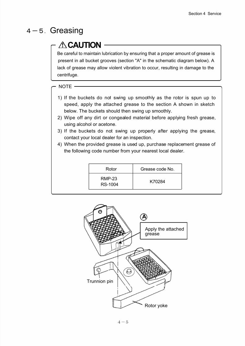
1) If the buckets do not swing up smoothly as the rotor is spun up to
speed, apply the attached grease to the section A shown in sketch
below. The buckets should then swing up smoothly.
2) Wipe off any dirt or congealed material before applying fresh grease,
using alcohol or acetone.
3) If the buckets do not swing up properly after applying the grease,
contact your local dealer for an inspection.
4) When the provided grease is used up, purchase replacement grease of
the following code number from your nearest local dealer.
Be careful to maintain lubrication by ensuring that a proper amount of grease is
present in all bucket grooves (section "A" in the schematic diagram below). A
lack of grease may allow violent vibration to occur, resulting in damage to the
centrifuge.
CAUTION
NOTE
Apply the attachedgrease
A
Rotor Grease code No.
RMP-23
RS-1004 K70284
4-5.Greasing
Section 4 Service
7/25/2019 Kubota 2420
http://slidepdf.com/reader/full/kubota-2420 39/70
4-6
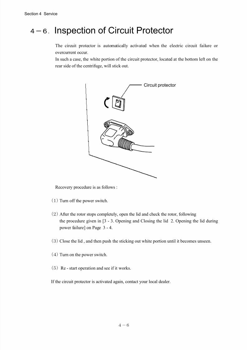
Circuit protector
4-6.Inspection of Circuit Protector
The circuit protector is automatically activated when the electric circuit failure or
overcurrent occur.
In such a case, the white portion of the circuit protector, located at the bottom left on therear side of the centrifuge, will stick out.
Recovery procedure is as follows :
(1)Turn off the power switch.
(2)After the rotor stops completely, open the lid and check the rotor, following
the procedure given in [3 - 3. Opening and Closing the lid 2. Opening the lid during
power failure] on Page 3 - 4.
(3)Close the lid , and then push the sticking out white portion until it becomes unseen.
(4)Turn on the power switch.
(5)Re - start operation and see if it works.
If the circuit protector is activated again, contact your local dealer.
Section 4 Service
7/25/2019 Kubota 2420
http://slidepdf.com/reader/full/kubota-2420 40/70
4-7
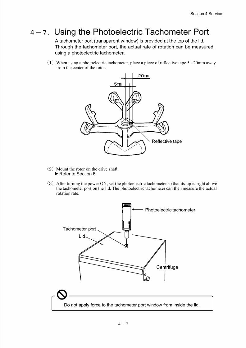
Do not apply force to the tachometer port window from inside the lid.
4-7.Using the Photoelectric Tachometer Port A tachometer port (transparent window) is provided at the top of the lid.
Through the tachometer port, the actual rate of rotation can be measured,
using a photoelectric tachometer.
(1)When using a photoelectric tachometer, place a piece of reflective tape 5 - 20mm awayfrom the center of the rotor.
(2)Mount the rotor on the drive shaft.Refer to Section 6.
(3)After turning the power ON, set the photoelectric tachometer so that its tip is right above the tachometer port on the lid. The photoelectric tachometer can then measure the actualrotation rate.
Section 4 Service
Tachometer port
Lid
Centrifuge
Photoelectric tachometer
20mm
5mm
Reflective tape
7/25/2019 Kubota 2420
http://slidepdf.com/reader/full/kubota-2420 41/70
4-8
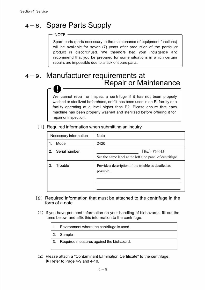
We cannot repair or inspect a centrifuge if it has not been properly
washed or sterilized beforehand, or if it has been used in an RI facility or a facility operating at a level higher than P2. Please ensure that each
machine has been properly washed and sterilized before offering it for
repair or inspection.
Spare parts (parts necessary to the maintenance of equipment functions)
will be available for seven (7) years after production of the particular
product is discontinued. We therefore beg your indulgence and
recommend that you be prepared for some situations in which certain
repairs are impossible due to a lack of spare parts.
NOTE
Necessary information Note
1. Model 2420
2. Serial number [Ex.]F60015See the name label at the left side panel of centrifuge.
3. Trouble Provide a description of the trouble as detailed as
possible.
1. Environment where the centrifuge is used.
2. Sample
3. Required measures against the biohazard.
4-8. Spare Parts Supply
4-9. Manufacturer requirements atRepair or Maintenance
[1]Required information when submitting an inquiry
[2]Required information that must be attached to the centrifuge in the
form of a note
(1)If you have pertinent information on your handling of biohazards, fill out the
items below, and affix this information to the centrifuge.
(2)Please attach a "Contaminant Elimination Certificate" to the centrifuge.
Refer to Page 4-9 and 4-10.
Section 4 Service
7/25/2019 Kubota 2420
http://slidepdf.com/reader/full/kubota-2420 42/70
4-9
Cont’d. on next page.
4-10. Product Preparation When Returning
Units for Repair or for Other Reasons
[1]Remove any contaminants from units or items that will be returned for
servicing
Prior to sending back our products (including accessories) for repair or for other
reasons, be sure to remove any and all contaminants.
[2] Attach a Contaminant Elimination Certificate
To eliminate possibly harmful contaminants, the user must take appropriate action on
his or her initiative. Fill out a "Contaminant Elimination Certificate" as shown on page
4-11, and attach it to the item to be returned.
[Caution]
"Contaminant" means radioactive materials, poisonous materials, contagious pathogens,
and so on. The preparatory procedure to eliminate all traces of such contaminants
therefore varies depending on the respective materials. Please take appropriate action to
prevent any possible hazard to personnel who will be handing the machine, equipment
or parts.
[3]Equipment contamination elimination goal
The elimination of contaminants from the equipment is aimed to safeguard the persons
who will inspect and repair the returned products at our facilities.
[4]If a Contaminant Elimination Certificate is not attached:
If a "Contaminant Elimination Certificate" is not attached to the returned products we
receive, we will contact the person in charge to confirm the details.
If we cannot confirm that potentially hazardous contaminants have been properly
eliminated, and we find that we cannot adequately deal with such matters ourselves, we
may return the products to the customer without taking further action.
[5]Contaminant elimination fee
If we are forced to perform the work of eliminating contaminants, we may request that
you pay a fee. Please note this stipulation beforehand.
Section 4 Service

7/25/2019 Kubota 2420
http://slidepdf.com/reader/full/kubota-2420 43/70
4-10
Please make a copy of this page and fill out the relevant details.
Contaminant Elimination Certificate
Date : , ,
Name:
Company / Institute:
Department:
Tel: Fax:
Address:
We hereby certify that contaminant elimination for this equipment has been
performed as follows:
Type of unit: Serial No.
Type of unit: Serial No.
Accessories :
Date when contamination elimination was carried out.
Date: , ,
Contaminants:
Method used:
Dealer notification:
Signature:
7/25/2019 Kubota 2420
http://slidepdf.com/reader/full/kubota-2420 44/70
5-1
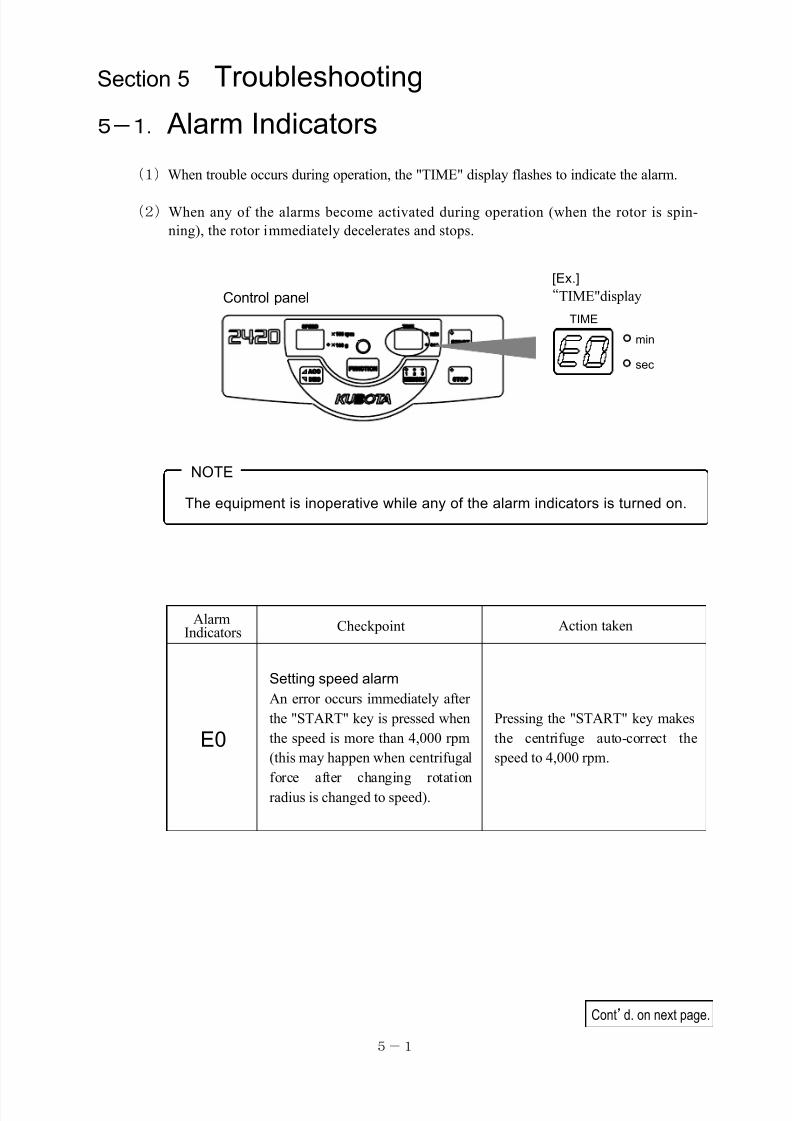
The equipment is inoperative while any of the alarm indicators is turned on.
NOTE
“TIME"display
[Ex.]
Control panel
min
sec
TIME
Cont’d. on next page.
AlarmIndicators Checkpoint Action taken
E0
Setting speed alarm
An error occurs immediately after
the "START" key is pressed when
the speed is more than 4,000 rpm
(this may happen when centrifugal
force after changing rotation
radius is changed to speed).
Pressing the "START" key makes
the centrifuge auto-correct the
speed to 4,000 rpm.
Section 5 Troubleshooting
5-1. Alarm Indicators
(1)When trouble occurs during operation, the "TIME" display flashes to indicate the alarm.
(2)When any of the alarms become activated during operation (when the rotor is spin-
ning), the rotor immediately decelerates and stops.
7/25/2019 Kubota 2420
http://slidepdf.com/reader/full/kubota-2420 45/70
5-2
"Alarm Indicators" and "Number of times of rotor use" at the time of rotor inspection
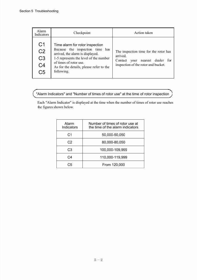
AlarmIndicators Checkpoint Action taken
C1
C2
C3
C4
C5
Time alarm for rotor inspection
Because the inspection time hasarrived, the alarm is displayed.
1-5 represents the level of the number
of times of rotor use.
As for the details, please refer to the
following.
The inspection time for the rotor has
arrived.
Contact your nearest dealer for
inspection of the rotor and bucket.
AlarmIndicators
Number of times of rotor use atthe time of the alarm indicators
C1 50,000-50,050
C2 80,000-80,050
C3 100,000-109,999
C4 110,000-119,999
C5 From 120,000
Each "Alarm Indicator" is displayed at the time when the number of times of rotor use reaches
the figures shown below.
Section 5 Troubleshooting
7/25/2019 Kubota 2420
http://slidepdf.com/reader/full/kubota-2420 46/70
5-3
“TIME"display[Ex.]Control panel
min
sec
TIME
The equipment is inoperative while any of the error indicators is turned on.
NOTE
Cont’d. on next page.
Error
Indicators Checkpoint Action taken
E1
Imbalance error
This indicator flashes and the
rotor stops rotation when
excessive vibration is
detected.
①Balance the load (samples or bucket).
②Remove dust and dirt from the sliding
surface and apply grease so that the bucket
on the swing rotor swings up smoothly.
Contact your local dealer for inspection when
this error continues to flash even after taking
the above measures.
E2Lid open error
This indicator lights when
the lid is open.
Close the lid completely.
When the error recurs, contact your nearest
dealer for inspection.
E3
Inverter Error This indicator flashes when
abnormal signal comes out
from the inverter.
After the rotor stops spinning, turn off power
supply once and turn on the power after about
30 seconds.
When the error recurs, contact your nearest
dealer for inspection.
5-2.Error Indicators
(1)When trouble occurs during operation, the “TIME" display flashes to show the error. The
error indicators are mentioned in the table below.
(2)When any of the error indicators turn on during operation (when the rotor is spinning),
the rotor immediately decelerates and stops.
Section 5 Troubleshooting
7/25/2019 Kubota 2420
http://slidepdf.com/reader/full/kubota-2420 47/70
5-4
Error Indicators Checkpoint Action taken
E4
Speed sensor error This indicator flashes when the
self-inspection function detects the
fault or abnormality in the speed
sensor.
After the rotor stops spinning, turnoff power supply once and turn on
the power after about 30 seconds.
When the error recurs, contact your
nearest dealer for inspection.
E6
Over speed error
Flashes to stop the rotation when
the maximum speed of thecorresponding rotor is exceeded.
Contact your local dealer for
inspection when this errorcontinues to flash.
E7
Speed error
This code appears when the
equipment did not start its
operation within 5 seconds after
the "START" key was pressed by
such causes as electric circuitfailures.
After the rotor stops spinning, turn
off the power supply once and turn
on the power after about 30
seconds.
If the error recurs, contact your
nearest dealer for inspection.
Section 5 Troubleshooting
7/25/2019 Kubota 2420
http://slidepdf.com/reader/full/kubota-2420 48/70
5-5
Cont’d. on next page.
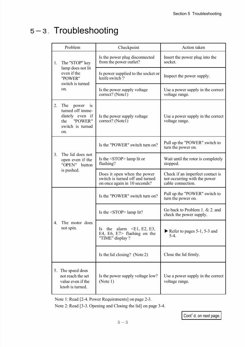
5-3.Troubleshooting
Note 1: Read [2-4. Power Requirements] on page 2-3.
Note 2: Read [3-3. Opening and Closing the lid] on page 3-4.
Section 5 Troubleshooting
Problem Checkpoint Action taken
1. The "STOP" key
lamp does not liteven if the
"POWER"switch is turned
on.
Is the power plug disconnected
from the power outlet?
Insert the power plug into the
socket.
Is power supplied to the socket or knife switch?
Inspect the power supply.
Is the power supply voltagecorrect? (Note1)
Use a power supply in the correctvoltage range.
2. The power isturned off imme-
diately even if
the "POWER"switch is turnedon.
Is the power supply voltage
correct? (Note1)
Use a power supply in the correct
voltage range.
3. The lid does not
open even if the"OPEN" button
is pushed.
Is the "POWER" switch turn on?Pull up the "POWER" switch toturn the power on.
Is the <STOP> lamp lit orflashing?
Wait until the rotor is completelystopped.
Does it open when the powerswitch is turned off and turned
on once again in 10 seconds?
Check if an imperfect contact isnot occurring with the power
cable connection.
4. The motor doesnot spin.
Is the "POWER" switch turn on?Pull up the "POWER" switch toturn the power on.
Is the <STOP> lamp lit?Go back to Problem 1. & 2. andcheck the power supply.
Is the alarm <E1, E2, E3,E4, E6, E7> flashing on the"TIME" display ?
Refer to pages 5-1, 5-3 and5-4.
Is the lid closing? (Note 2) Close the lid firmly.
5. The speed does
not reach the set
value even if the
knob is turned.
Is the power supply voltage low?
(Note 1)
Use a power supply in the correct
voltage range.
7/25/2019 Kubota 2420
http://slidepdf.com/reader/full/kubota-2420 49/70
5-6
●The rotor or metal tubes has been found to be damaged or corroded.
● A burnt smell comes out of the equipment.
●You receive a minor electrification when you touch the equipment body
by a naked hand.
●Some other abnormality or failure has been found occurring.
When operation centrifuge is interrupted by some abnormality, failure or
for repairs, always turn off the "POWER" switch and attach "DO NOT
USE" stickers to the rotor and the centrifuge before contacting your
nearest dealer.
NOTE
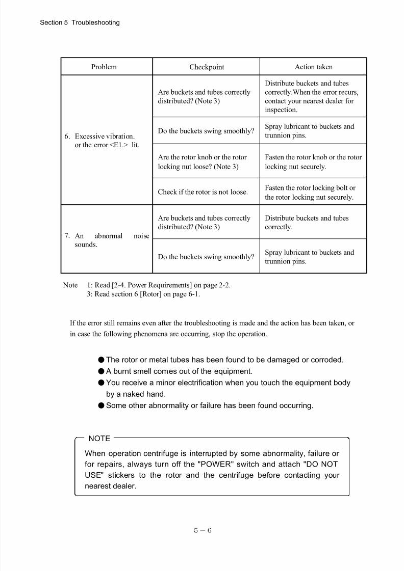
Note 1: Read [2-4. Power Requirements] on page 2-2.
3: Read section 6 [Rotor] on page 6-1.
If the error still remains even after the troubleshooting is made and the action has been taken, or
in case the following phenomena are occurring, stop the operation.
Section 5 Troubleshooting
Problem Checkpoint Action taken
6. Excessive vibration.
or the error <E1.> lit.
Are buckets and tubes correctly
distributed? (Note 3)
Distribute buckets and tubes
correctly.When the error recurs,
contact your nearest dealer forinspection.
Do the buckets swing smoothly?Spray lubricant to buckets and
trunnion pins.
Are the rotor knob or the rotor
locking nut loose? (Note 3)
Fasten the rotor knob or the rotor
locking nut securely.
Check if the rotor is not loose.Fasten the rotor locking bolt or
the rotor locking nut securely.
7. An abnormal noise
sounds.
Are buckets and tubes correctly
distributed? (Note 3)
Distribute buckets and tubes
correctly.
Do the buckets swing smoothly?Spray lubricant to buckets and
trunnion pins.
7/25/2019 Kubota 2420
http://slidepdf.com/reader/full/kubota-2420 50/70
6-1
If the drive pin of the drive shaft is
not set in the groove of the rotor
bottom surface, the bucket
intervention prevention plate is
not be fixed and moves up and
down.
In such a case, re-install the
rotor.
Do not start the operation when
the rotor locking nut is removed.
CAUTIONMake sure that the rotor yoke is firmly fastened to the drive shaft
with the rotor locking nut.
Since the rotor is not fastened onto the shaft when these parts are loose,excessive
vibrations will occur and damage the equipment and the rotor may fly off inflicting
physical injury.
(NOTE)T-type box wrench will be attached to the
rotor as standard accessary, when the
second rotor is purchased.
Section 6 Rotor
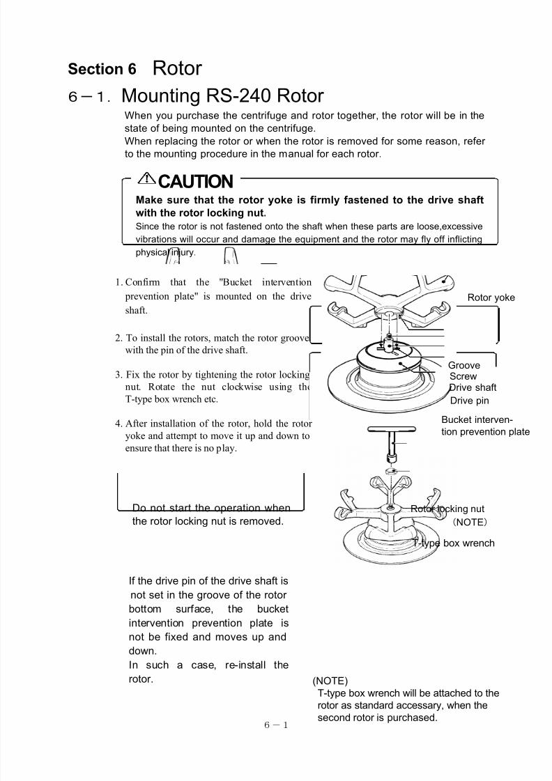
6-1.Mounting RS-240 Rotor When you purchase the centrifuge and rotor together, the rotor will be in the
state of being mounted on the centrifuge.
When replacing the rotor or when the rotor is removed for some reason, refer
to the mounting procedure in the manual for each rotor.
1. Confirm that the "Bucket intervention
prevention plate" is mounted on the drive
shaft.
2. To install the rotors, match the rotor groove
with the pin of the drive shaft.
3. Fix the rotor by tightening the rotor locking
nut. Rotate the nut clockwise using the
T-type box wrench etc.
4. After installation of the rotor, hold the rotor
yoke and attempt to move it up and down to
ensure that there is no play.
Drive pin
Drive shaft
Bucket interven-
tion prevention plate
GrooveScrew
Rotor yoke
(NOTE)
Rotor locking nut
T-type box wrench
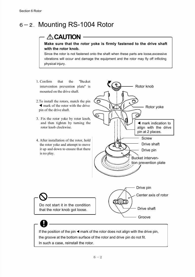
7/25/2019 Kubota 2420
http://slidepdf.com/reader/full/kubota-2420 51/70
6-2
CAUTIONMake sure that the rotor yoke is firmly fastened to the drive shaft
with the rotor knob.Since the rotor is not fastened onto the shaft when these parts are loose,excessive
vibrations will occur and damage the equipment and the rotor may fly off inflicting
physical injury.
Drive pin
Drive shaft
Center axis of rotor
Groove
If the position of the pin ▲mark of the rotor does not align with the drive pin,
the groove at the bottom surface of the rotor and drive pin do not fit.
In such a case, reinstall the rotor.
Do not start it in the condition
that the rotor knob got loose.
6-2.Mounting RS-1004 Rotor
1. Confirm that the "Bucket
intervention prevention plate" is
mounted on the drive shaft.
2.To install the rotors, match the pin
▲mark of the rotor with the drive
pin of the drive shaft.
3. Fix the rotor yoke by rotor knob,
and then tighten by turning the
rotor knob clockwise.
4. After installation of the rotor, hold
the rotor yoke and attempt to move it up and down to ensure that there
is no play.
Section 6 Rotor
Drive pinDrive shaft
Bucket interven-
tion prevention plate
▲mark indication to
align with the drive
pin at 2 places.
Screw
Rotor knob
Rotor yoke
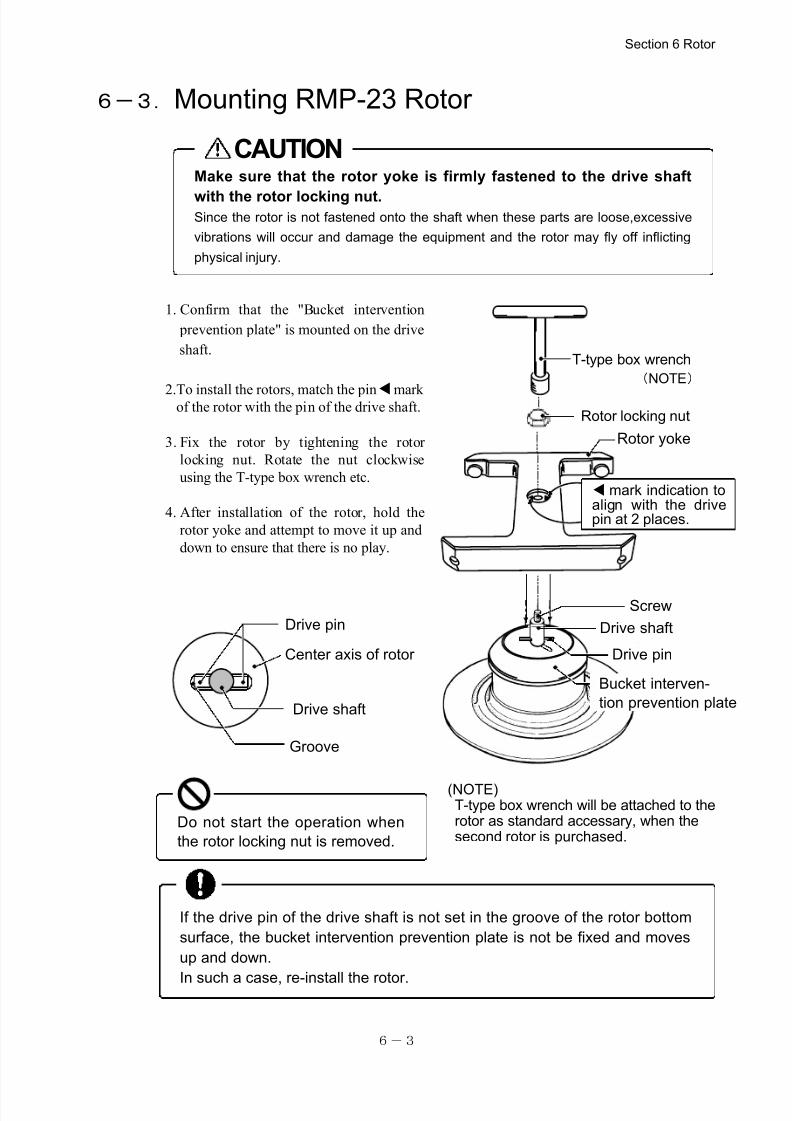
7/25/2019 Kubota 2420
http://slidepdf.com/reader/full/kubota-2420 52/70
6-3
If the drive pin of the drive shaft is not set in the groove of the rotor bottom
surface, the bucket intervention prevention plate is not be fixed and moves
up and down.
In such a case, re-install the rotor.
Drive pin
Drive shaft
Center axis of rotor
CAUTIONMake sure that the rotor yoke is firmly fastened to the drive shaft
with the rotor locking nut.Since the rotor is not fastened onto the shaft when these parts are loose,excessive
vibrations will occur and damage the equipment and the rotor may fly off inflicting
physical injury.
Groove
Do not start the operation when
the rotor locking nut is removed.
(NOTE)T-type box wrench will be attached to therotor as standard accessary, when thesecond rotor is purchased.
6-3.Mounting RMP-23 Rotor
1. Confirm that the "Bucket intervention
prevention plate" is mounted on the drive
shaft.
2.To install the rotors, match the pin ▲mark of the rotor with the pin of the drive shaft.
3. Fix the rotor by tightening the rotor
locking nut. Rotate the nut clockwise
using the T-type box wrench etc.
4. After installation of the rotor, hold the
rotor yoke and attempt to move it up and
down to ensure that there is no play.
Section 6 Rotor
Drive pin
Drive shaft
Bucket interven-
tion prevention plate
Rotor locking nut
Screw
Rotor yoke
▲mark indication to align with the drivepin at 2 places.
T-type box wrench
(NOTE)
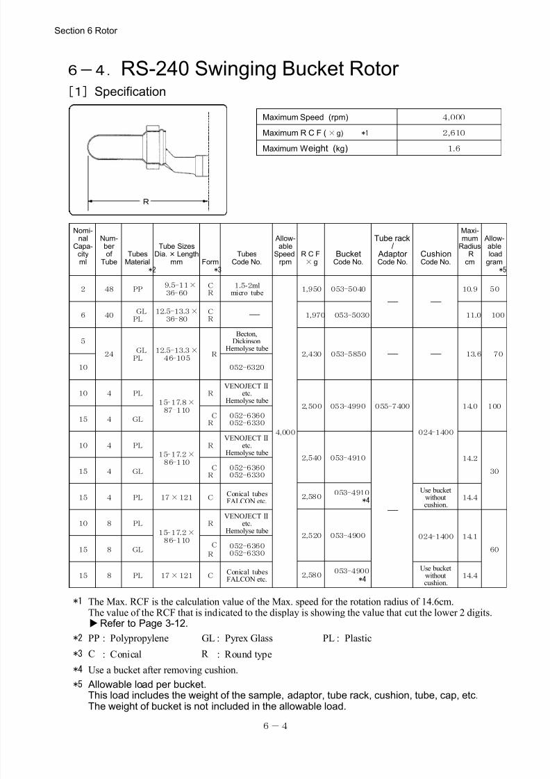
7/25/2019 Kubota 2420
http://slidepdf.com/reader/full/kubota-2420 53/70
6-4
R
Maximum Speed (rpm) 4,000
Maximum R C F ( ×g) *1 2,610Maximum Weight (kg) 1.6
Nomi-nal
Capa-cityml
Num-ber of
TubeTubes
Material
*2
Tube SizesDia.×Length
mm Form
*3
TubesCode No.
Allow-able
Speedrpm
R C F×g
BucketCode No.
Tube rack/
Adaptor Code No.
CushionCode No.
Maxi-mum
Radius Rcm
Allow-able loadgram
*5
2 48 PP 9.5-11×
36-60CR
1.5-2mlmicro tube
4,000
1,950 053-5040
- -10.9 50
6 40 GL
PL12.5-13.3×
36-80CR - 1,970 053-5030 11.0 100
5
24 GL
PL12.5-13.3×
46-105 R
Becton,Dickinson
Hemolyse tube2,430 053-5850 - - 13.6 70
10 052-6320
10 4 PL
15-17.8×
87-110
RVENOJECTⅡ
etc.Hemolyse tube
2,500 053-4990 055-7400
024-1400
14.0 10015 4 GL
CR
052-6360052-6330
10 4 PL
15-17.2×86-110
RVENOJECTⅡ
etc.Hemolyse tube
2,540 053-4910
-
14.2
3015 4 GL C
R052-6360052-6330
2,580 053-4910 *415 4 PL 17×121 C
Conical tubesFALCON etc.
Use bucketwithoutcushion.
14.4
2,520 053-4900
10 8 PL
15-17.2×86-110
RVENOJECTⅡ
etc.Hemolyse tube
024-1400 14.1
6015 8 GL CR
052-6360052-6330
2,580 053-4900 *4
15 8 PL 17×121 CConical tubesFALCON etc.
Use bucketwithoutcushion.
14.4
*1 The Max. RCF is the calculation value of the Max. speed for the rotation radius of 14.6cm.The value of the RCF that is indicated to the display is showing the value that cut the lower 2 digits. Refer to Page 3-12.
*2 PP : Polypropylene GL : Pyrex Glass PL : Plastic
*3 C : Conical R : Round type
*4 Use a bucket after removing cushion.
*5 Allowable load per bucket.This load includes the weight of the sample, adaptor, tube rack, cushion, tube, cap, etc.The weight of bucket is not included in the allowable load.
6-4.RS-240 Swinging Bucket Rotor [1]Specification
Section 6 Rotor
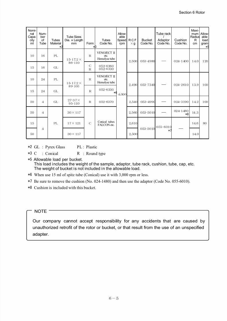
7/25/2019 Kubota 2420
http://slidepdf.com/reader/full/kubota-2420 54/70
6-5
Our company cannot accept responsibility for any accidents that are caused by
unauthorized retrofit of the rotor or bucket, or that result from the use of an unspecified
adapter.
NOTE
Nomi-nal
Capa-cityml
Num-ber of
TubeTubes
Material *2
Tube SizesDia.×Length
mm Form *3
TubesCode No.
Allow-able
Speedrpm
R C F×g
BucketCode No.
Tube rack/
Adaptor Code No.
CushionCode No.
Maxi-mum
Radius Rcm
Allow-ableload
gram *5
10 16 PL15-17.2×
86-110
R
VENOJECTⅡ
etc.Hemolyse tube
4,000
2,500 053-4980 - 024-1400 14.0 120
15 16 GL C
R
052-6360052-6330
10 24 PL
15-17.2×89-105
RVENOJECTⅡ
etc.Hemolyse tube
2,490 053-7340 - 024-2610 13.9 100
15 24 GL R 052-6330 *6
50 4 GL 27-37×
95-110 R 052-6370 2,540 053-4990 - 024-3190 14.2 100
50 4
PL
30×117
C Conical tubes
FALCON etc.
2,560 053-5010 - 024-1480
*8 14.3
8015
4
17×121 2,610
053-5010055-6010
*7 -
14.6
50 30×117 2,500 14.0
*2 GL : Pyrex Glass PL : Plastic
*3 C : Conical R : Round type
*5 Allowable load per bucket.This load includes the weight of the sample, adaptor, tube rack, cushion, tube, cap, etc.
The weight of bucket is not included in the allowable load.*6 When use 15 ml of spitz tube (Conical) use it with 3,000 rpm or less.
*7 Be sure to remove the cushion (No. 024-1480) and then use the adaptor (Code No. 055-6010).
*8 Cushion is included with this bucket.
Section 6 Rotor
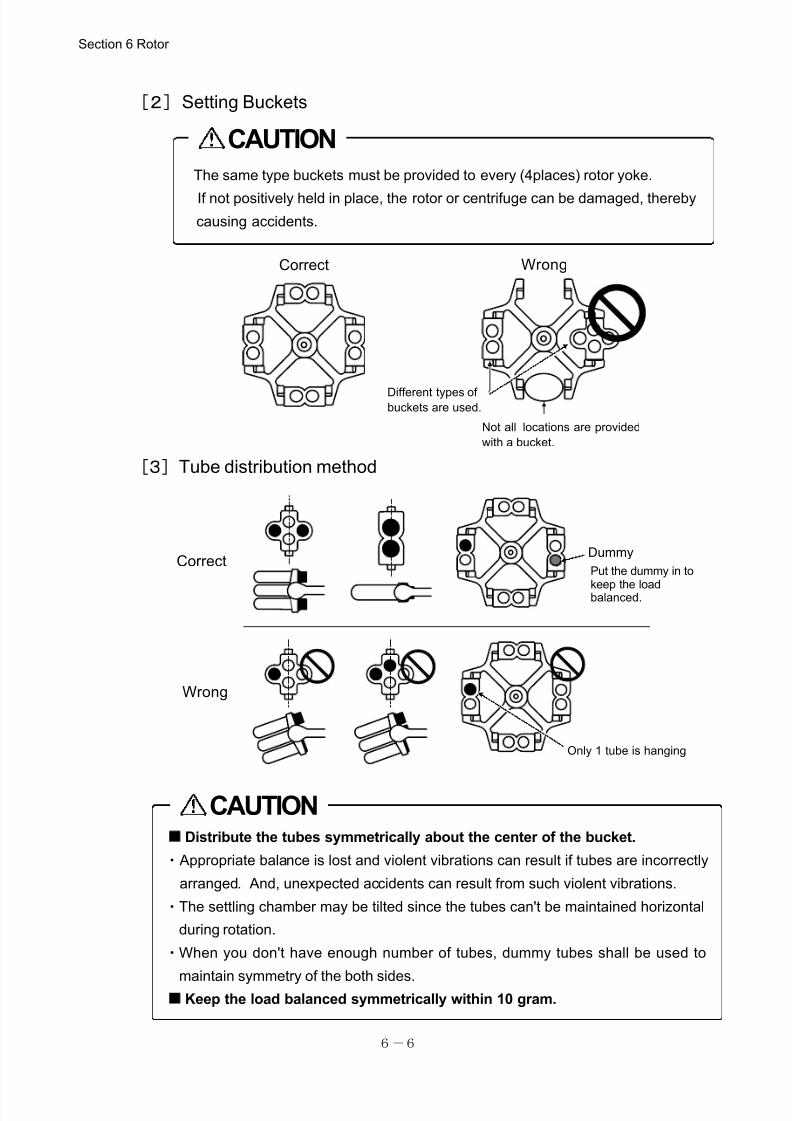
7/25/2019 Kubota 2420
http://slidepdf.com/reader/full/kubota-2420 55/70
6-6
The same type buckets must be provided to every (4places) rotor yoke.
If not positively held in place, the rotor or centrifuge can be damaged, thereby
causing accidents.
CAUTION
■
Distribute the tubes symmetrically about the center of the bucket.
・ Appropriate balance is lost and violent vibrations can result if tubes are incorrectly
arranged. And, unexpected accidents can result from such violent vibrations.
・The settling chamber may be tilted since the tubes can't be maintained horizontal
during rotation.
・When you don't have enough number of tubes, dummy tubes shall be used to
maintain symmetry of the both sides.■
Keep the load balanced symmetrically within 10 gram.
CAUTION
Correct Wrong
Not all locations are provided
with a bucket.
Different types ofbuckets are used.
[2]Setting Buckets
[3]Tube distribution method
Section 6 Rotor
Only 1 tube is hanging
Dummy
Put the dummy in to
keep the loadbalanced.
Correct
Wrong
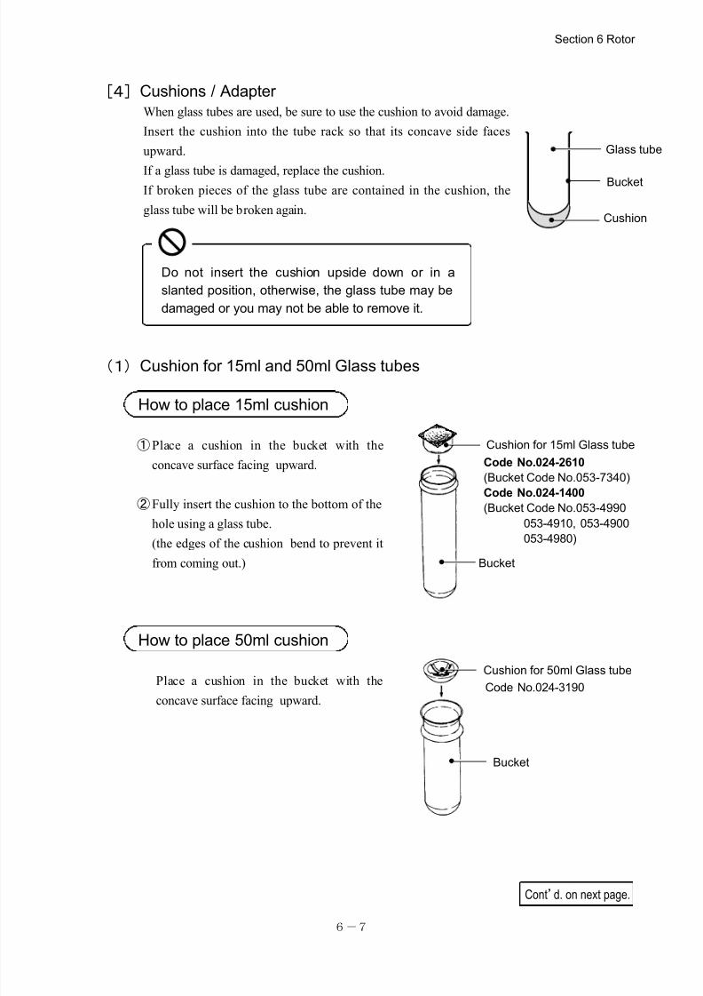
7/25/2019 Kubota 2420
http://slidepdf.com/reader/full/kubota-2420 56/70
6-7
Do not insert the cushion upside down or in a
slanted position, otherwise, the glass tube may be
damaged or you may not be able to remove it.
Cushion for 15ml Glass tube
Bucket
Code No.024-2610
(Bucket Code No.053-7340)
Code No.024-1400
(Bucket Code No.053-4990
053-4910, 053-4900053-4980)
Cushion for 50ml Glass tube
Code No.024-3190
Bucket
Cont’d. on next page.
[4]Cushions / Adapter
When glass tubes are used, be sure to use the cushion to avoid damage.
Insert the cushion into the tube rack so that its concave side faces
upward.
If a glass tube is damaged, replace the cushion.If broken pieces of the glass tube are contained in the cushion, the
glass tube will be broken again.
(1)Cushion for 15ml and 50ml Glass tubes
How to place 15ml cushion
①Place a cushion in the bucket with the
concave surface facing upward.
②Fully insert the cushion to the bottom of the
hole using a glass tube.(the edges of the cushion bend to prevent it
from coming out.)
How to place 50ml cushion
Place a cushion in the bucket with the
concave surface facing upward.
Section 6 Rotor
Glass tube
Bucket
Cushion
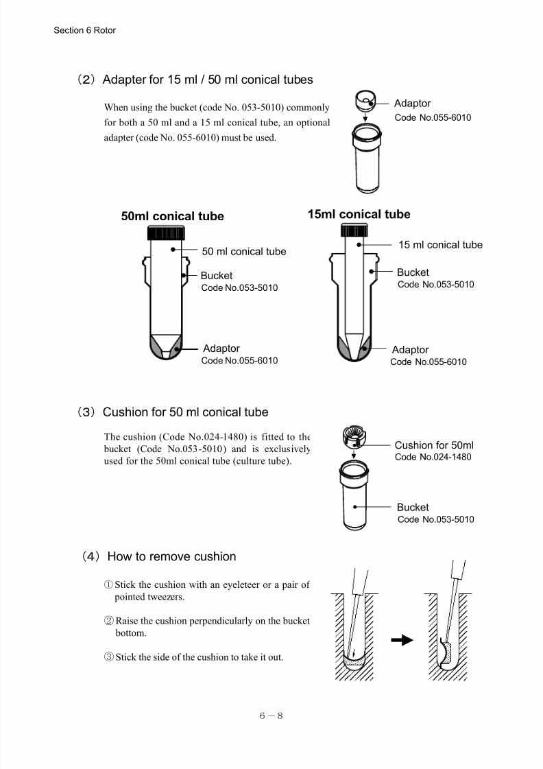
7/25/2019 Kubota 2420
http://slidepdf.com/reader/full/kubota-2420 57/70
6-8
Code No.053-5010
50 ml conical tube
Bucket
15 ml conical tube
50ml conical tube 15ml conical tube
Adaptor Code No.055-6010
Code No.053-5010Bucket
Adaptor Code No.055-6010
(2) Adapter for 15 ml / 50 ml conical tubes
When using the bucket (code No. 053-5010) commonly
for both a 50 ml and a 15 ml conical tube, an optional
adapter (code No. 055-6010) must be used.
(3)Cushion for 50 ml conical tube
The cushion (Code No.024-1480) is fitted to the
bucket (Code No.053-5010) and is exclusively
used for the 50ml conical tube (culture tube).
(4)How to remove cushion
①Stick the cushion with an eyeleteer or a pair of
pointed tweezers.
②Raise the cushion perpendicularly on the bucket
bottom.
③Stick the side of the cushion to take it out.
Section 6 Rotor
Adaptor
Code No.055-6010
Code No.053-5010
Bucket
Cushion for 50mlCode No.024-1480
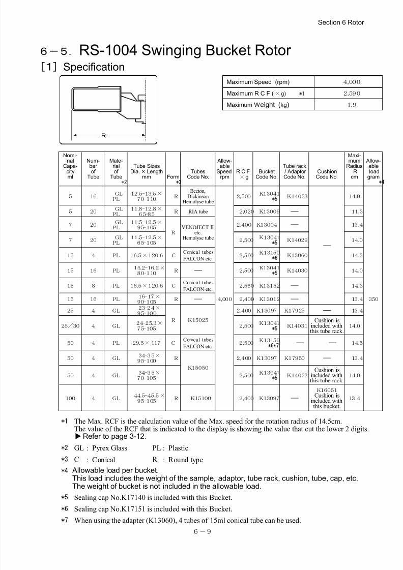
7/25/2019 Kubota 2420
http://slidepdf.com/reader/full/kubota-2420 58/70
6-9
R
Maximum Speed (rpm) 4,000
Maximum R C F (×g) *1 2,590
Maximum Weight (kg) 1.9
Nomi-nal
Capa-cityml
Num-ber of
Tube
Mate-rialof
Tube *2
Tube SizesDia.×Length
mm Form *3
TubesCode No.
Allow-able
Speedrpm
R C F×g
BucketCode No.
Tube rack/ Adaptor Code No.
CushionCode No.
Maxi-mum
Radius Rcm
Allow-able loadgram *4
5 16 GL
PL
12.5-13.5×
70-110 R
Becton,Dickinson
Hemolyse tube
4,000
2,500 K13041
*5 K14033
-
14.0
350
5 20 GL
PL11.8-12.8×
65-85 R RIA tube 2,020 K13009 - 11.3
7 20 GL
PL11.5-12.5×
95-105R
VENOJECTⅡetc.
Hemolyse tube
2,400 K13004 - 13.4
7 20 GL
PL11.5-12.5×
65-105 2,500
K13041 *5
K14029 14.0
15 4 PL 16.5×120.6 CConical tubes
FALCON etc. 2,560
K13150 *6 K13060 14.3
15 16 PL 15.2-16.2×
80-110 R - 2,500
K13041 *5
K14030 14.0
15 8 PL 16.5×120.6 CConical tubes
FALCON etc. 2,560 K13152 - 14.3
15 16 PL 16-17×
90-105 R - 2,400 K13012 - 13.4
25 4 GL 23-24×
95-100
R K15025
2,400 K13097 K17925 - 13.4
25/30 4 GL 24-25.3×
75-105 2,500
K13041 *5
K14031Cushion is
included withthis tube rack.
14.0
50 4 PL 29.5×117 CConical tubes
FALCON etc. 2,590
K13150 *6*7 - - 14.5
50 4 GL 34-35×
95-100 R
K15050
2,400 K13097 K17950 - 13.4
50 4 GL 34-35×
70-105 2,500
K13041 *5 K14032
Cushion isincluded withthis tube rack.
14.0
100 4 GL
44.5-45.5×
95-105 R K15100 2,400 K13097 -
K16051Cushion is
included withthis bucket.
13.4
*1 The Max. RCF is the calculation value of the Max. speed for the rotation radius of 14.5cm.The value of the RCF that is indicated to the display is showing the value that cut the lower 2 digits.Refer to page 3-12.
*2 GL : Pyrex Glass PL : Plastic
*3 C : Conical R : Round type
*4 Allowable load per bucket.This load includes the weight of the sample, adaptor, tube rack, cushion, tube, cap, etc.The weight of bucket is not included in the allowable load.
*5 Sealing cap No.K17140 is included with this Bucket.*6 Sealing cap No.K17151 is included with this Bucket.
*7 When using the adapter (K13060), 4 tubes of 15ml conical tube can be used.
6-5.RS-1004 Swinging Bucket Rotor [1]Specification
Section 6 Rotor
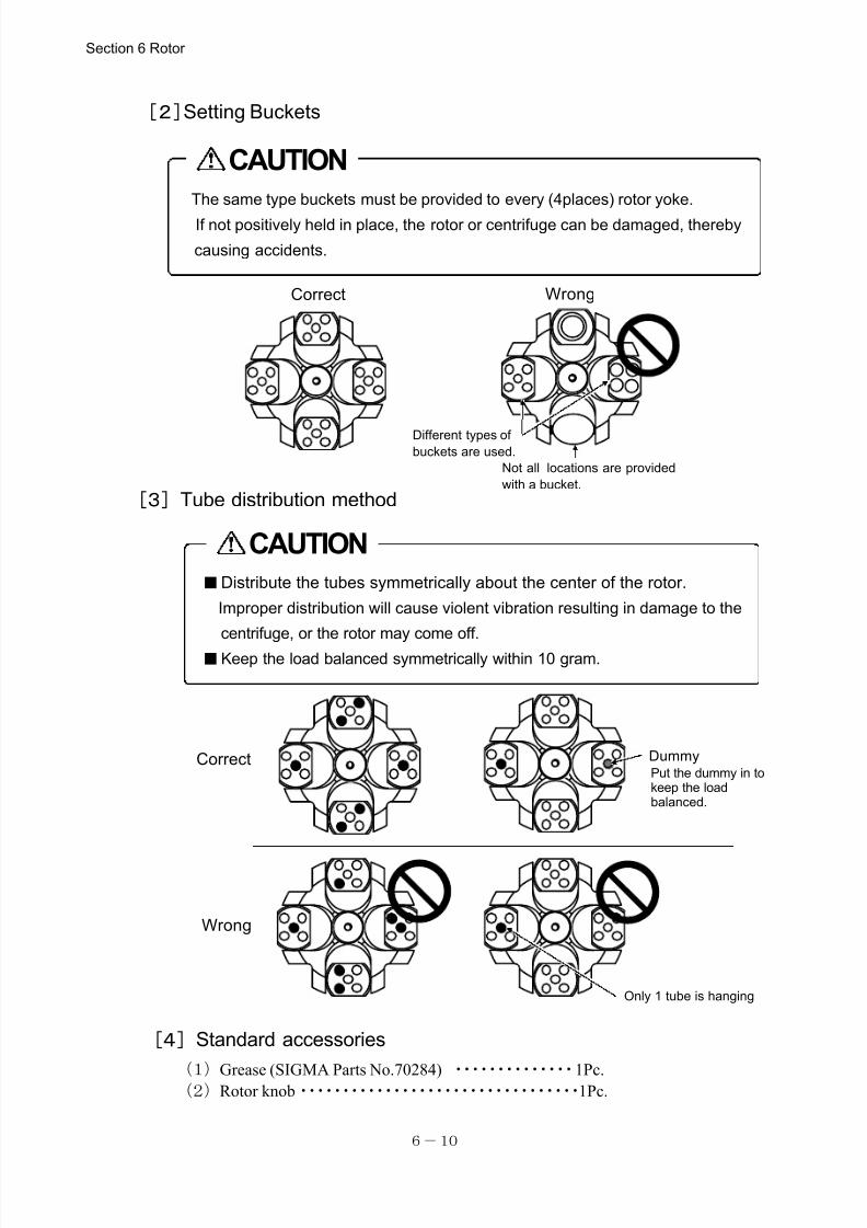
7/25/2019 Kubota 2420
http://slidepdf.com/reader/full/kubota-2420 59/70
6-10
The same type buckets must be provided to every (4places) rotor yoke.
If not positively held in place, the rotor or centrifuge can be damaged, thereby
causing accidents.
CAUTION
■Distribute the tubes symmetrically about the center of the rotor.
Improper distribution will cause violent vibration resulting in damage to the
centrifuge, or the rotor may come off.
■Keep the load balanced symmetrically within 10 gram.
CAUTION
Correct Wrong
Not all locations are provided
with a bucket.
Different types of
buckets are used.
Only 1 tube is hanging
DummyCorrect
Wrong
Put the dummy in tokeep the loadbalanced.
[2]Setting Buckets
[3]Tube distribution method
[4]Standard accessories
(1)Grease (SIGMA Parts No.70284) ・・・・・・・・・・・・・・1Pc.(2)Rotor knob・・・・・・・・・・・・・・・・・・・・・・・・・・・・・・・・・1Pc.
Section 6 Rotor
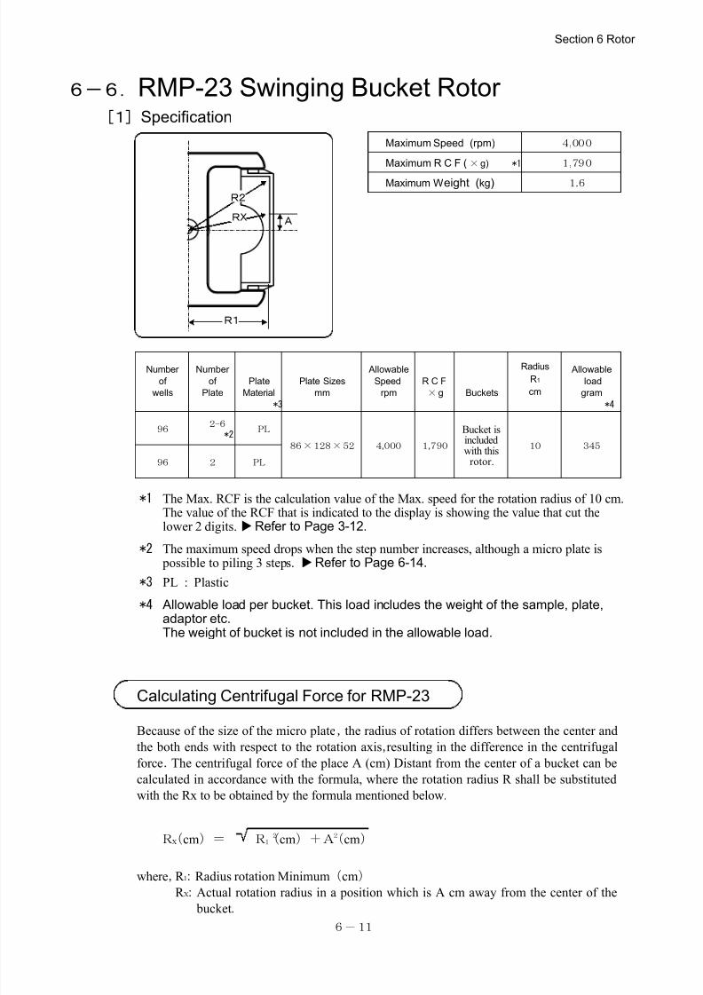
7/25/2019 Kubota 2420
http://slidepdf.com/reader/full/kubota-2420 60/70
6-11
R1
ARX
R2
Maximum Speed (rpm) 4,000
Maximum R C F ( ×g) *1 1,790
Maximum Weight (kg) 1.6
Number
of
wells
Number
of
Plate
Plate
Material
*3
Plate Sizes
mm
Allowable
Speed
rpm
R C F
×g Buckets
Radius
R1
cm
Allowable
load
gram
*4
96 2-6
*2 PL
86×128×52 4,000 1,790
Bucket isincludedwith this
rotor.
10 345
96 2 PL
*1 The Max. RCF is the calculation value of the Max. speed for the rotation radius of 10 cm.The value of the RCF that is indicated to the display is showing the value that cut the
lower 2 digits.Refer to Page 3-12.
*2 The maximum speed drops when the step number increases, although a micro plate is possible to piling 3 steps. Refer to Page 6-14.
*3 PL : Plastic
*4 Allowable load per bucket. This load includes the weight of the sample, plate,adaptor etc.The weight of bucket is not included in the allowable load.
6-6.RMP-23 Swinging Bucket Rotor [1]Specification
Calculating Centrifugal Force for RMP-23
Because of the size of the micro plate,the radius of rotation differs between the center and
the both ends with respect to the rotation axis,resulting in the difference in the centrifugal
force.The centrifugal force of the place A (cm) Distant from the center of a bucket can be
calculated in accordance with the formula, where the rotation radius R shall be substituted
with the Rx to be obtained by the formula mentioned below.
where,R 1:Radius rotation Minimum(cm)R X:Actual rotation radius in a position which is A cm away from the center of the
bucket.
Section 6 Rotor
RX(cm)= R 21(cm)+A2(cm)
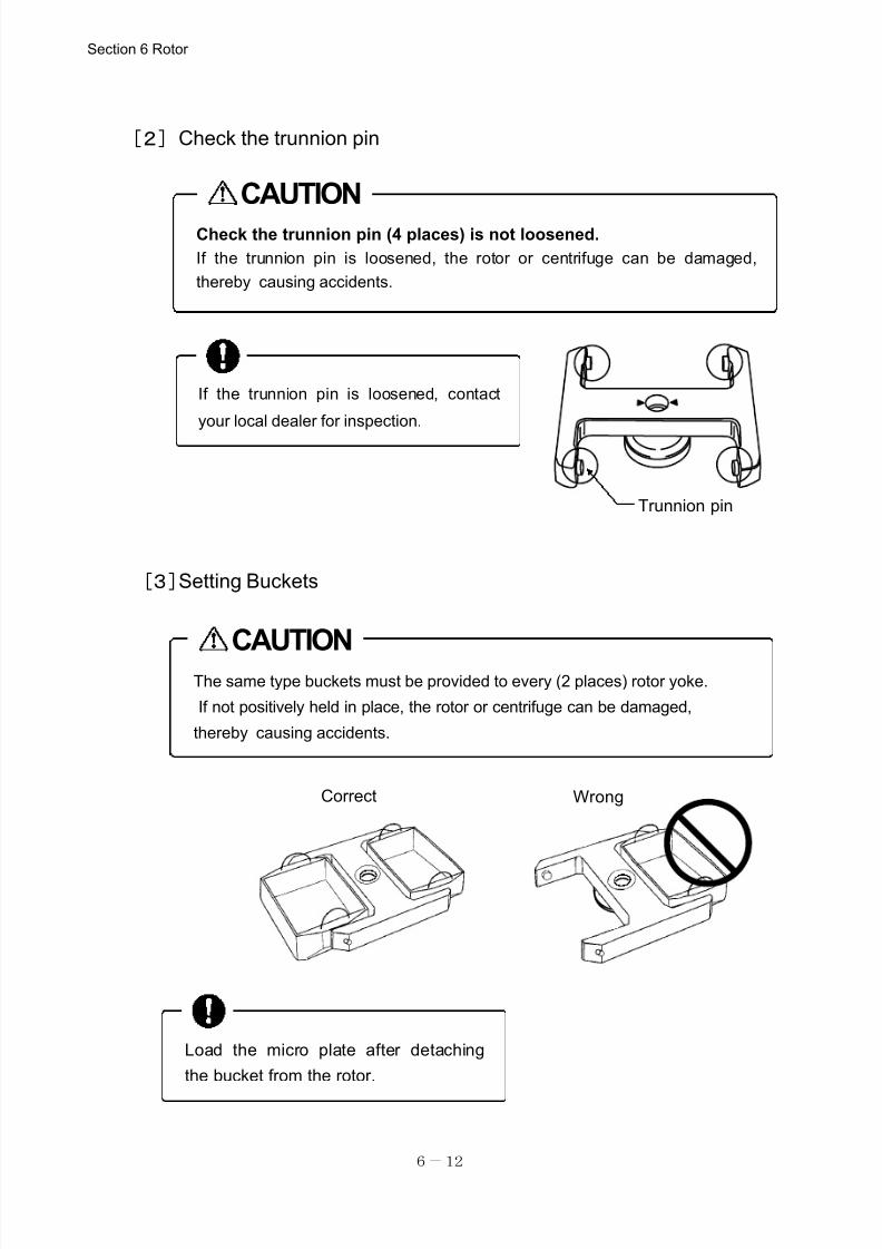
7/25/2019 Kubota 2420
http://slidepdf.com/reader/full/kubota-2420 61/70
6-12
The same type buckets must be provided to every (2 places) rotor yoke.
If not positively held in place, the rotor or centrifuge can be damaged,
thereby causing accidents.
CAUTION
If the trunnion pin is loosened, contact
your local dealer for inspection.
Trunnion pin
CAUTION
Check the trunnion pin (4 places) is not loosened.
If the trunnion pin is loosened, the rotor or centrifuge can be damaged,
thereby causing accidents.
Load the micro plate after detaching
the bucket from the rotor.
[2]Check the trunnion pin
[3]Setting Buckets
Section 6 Rotor
Correct Wrong
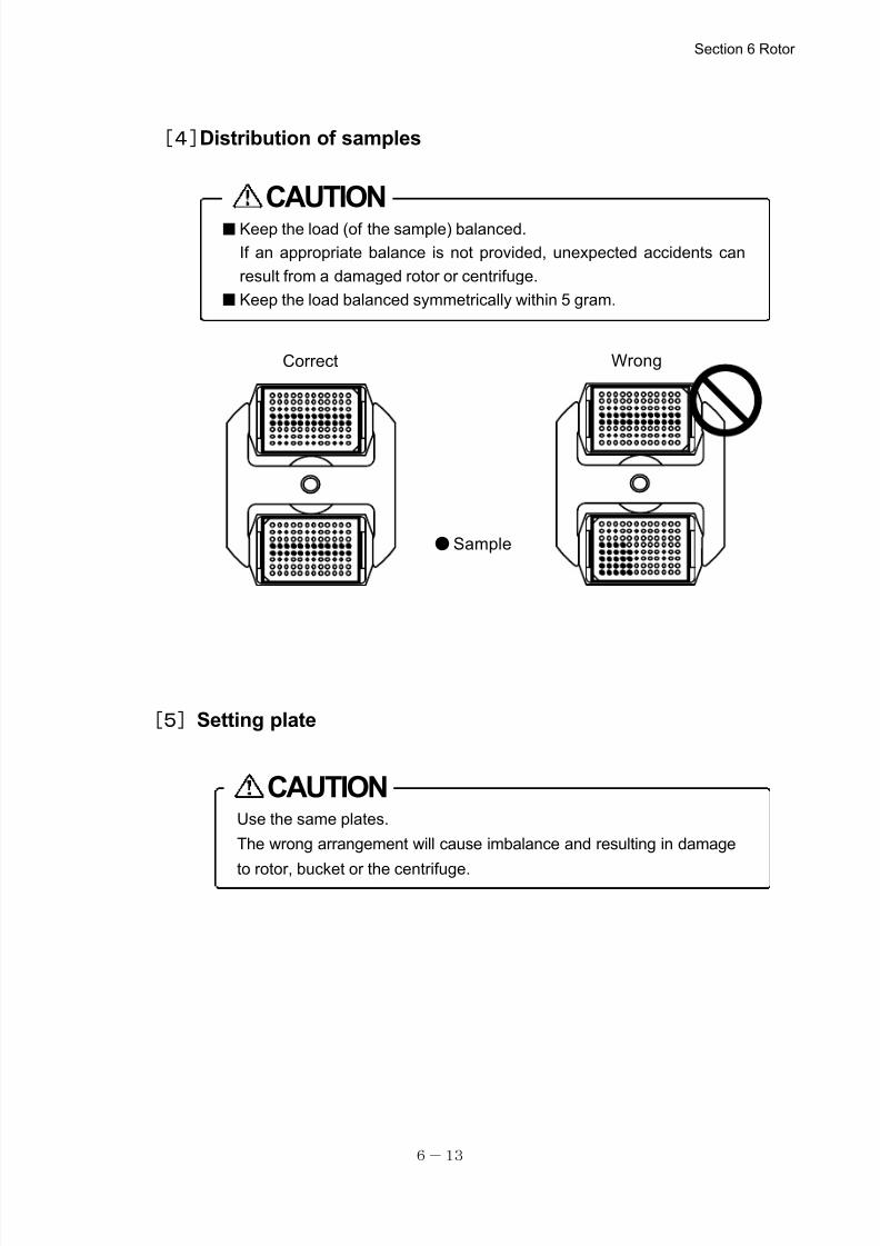
7/25/2019 Kubota 2420
http://slidepdf.com/reader/full/kubota-2420 62/70
6-13
■Keep the load (of the sample) balanced.
If an appropriate balance is not provided, unexpected accidents can
result from a damaged rotor or centrifuge.
■Keep the load balanced symmetrically within 5 gram.
CAUTION
Correct Wrong
●Sample
Use the same plates.
The wrong arrangement will cause imbalance and resulting in damage
to rotor, bucket or the centrifuge.
CAUTION
[4]Distribution of samples
[5]Setting plate
Section 6 Rotor
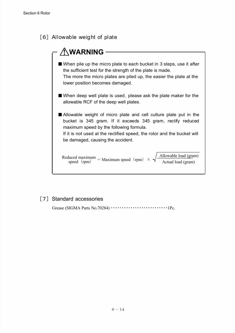
7/25/2019 Kubota 2420
http://slidepdf.com/reader/full/kubota-2420 63/70
6-14
■When pile up the micro plate to each bucket in 3 steps, use it after
the sufficient test for the strength of the plate is made.
The more the micro plates are piled up, the easier the plate at the
lower position becomes damaged.
■When deep well plate is used,please ask the plate maker for the
allowable RCF of the deep well plates.
■ Allowable weight of micro plate and cell culture plate put in thebucket is 345 gram. If it exceeds 345 gram, rectify reduced
maximum speed by the following formula.
If it is not used at the rectified speed, the rotor and the bucket will
be damaged, causing the accident.
Allowable load (gram)
Actual load (gram)Reduced maximum
=Maximum speed(rpm)×
speed(rpm)
WARNING
[6] Allowable weight of plate
[7]Standard accessories
Grease (SIGMA Parts No.70284)・・・・・・・・・・・・・・・・・・・・・・・・・・1Pc.
Section 6 Rotor
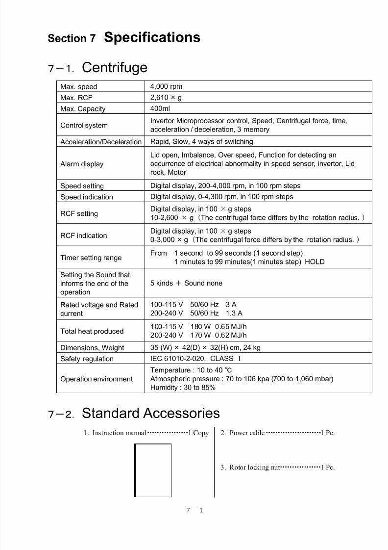
7/25/2019 Kubota 2420
http://slidepdf.com/reader/full/kubota-2420 64/70
7-1
Max. speed 4,000 rpm
Max. RCF 2,610×g
Max. Capacity 400ml
Control systemInvertor Microprocessor control, Speed, Centrifugal force, time,
acceleration / deceleration, 3 memory
Acceleration/Deceleration Rapid, Slow, 4 ways of switching
Alarm display
Lid open, Imbalance, Over speed, Function for detecting an
occurrence of electrical abnormality in speed sensor, invertor, Lid
rock, Motor
Speed setting Digital display, 200-4,000 rpm, in 100 rpm steps
Speed indication Digital display, 0-4,300 rpm, in 100 rpm steps
RCF settingDigital display, in 100 ×g steps
10-2,600 × g(The centrifugal force differs by the rotation radius.)
RCF indicationDigital display, in 100 ×g steps
0-3,000×g(The centrifugal force differs by the rotation radius.)
Timer setting rangeFrom 1 second to 99 seconds (1 second step)
1 minutes to 99 minutes(1 minutes step) HOLD
Setting the Sound that
informs the end of the
operation
5 kinds+ Sound none
Rated voltage and Rated
current
100-115 V 50/60 Hz 3 A
200-240 V 50/60 Hz 1.3 A
Total heat produced100-115 V 180 W 0.65 MJ/h
200-240 V 170 W 0.62 MJ/h
Dimensions, Weight 35 (W)× 42(D)× 32(H) cm, 24 kg
Safety regulation IEC 61010-2-020, CLASS Ⅰ
Operation environment
Temperature : 10 to 40℃ Atmospheric pressure : 70 to 106 kpa (700 to 1,060 mbar)
Humidity : 30 to 85%
Section 7 Specifications
7-1.Centrifuge
7-2.Standard Accessories 1. Instruction manual・・・・・・・・・・・・・・・・・1 Copy 2. Power cable・・・・・・・・・・・・・・・・・・・・・・・1 Pc.
3. Rotor locking nut・・・・・・・・・・・・・・・・・1 Pc.
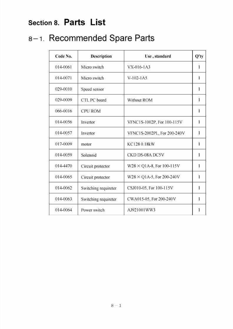
7/25/2019 Kubota 2420
http://slidepdf.com/reader/full/kubota-2420 65/70
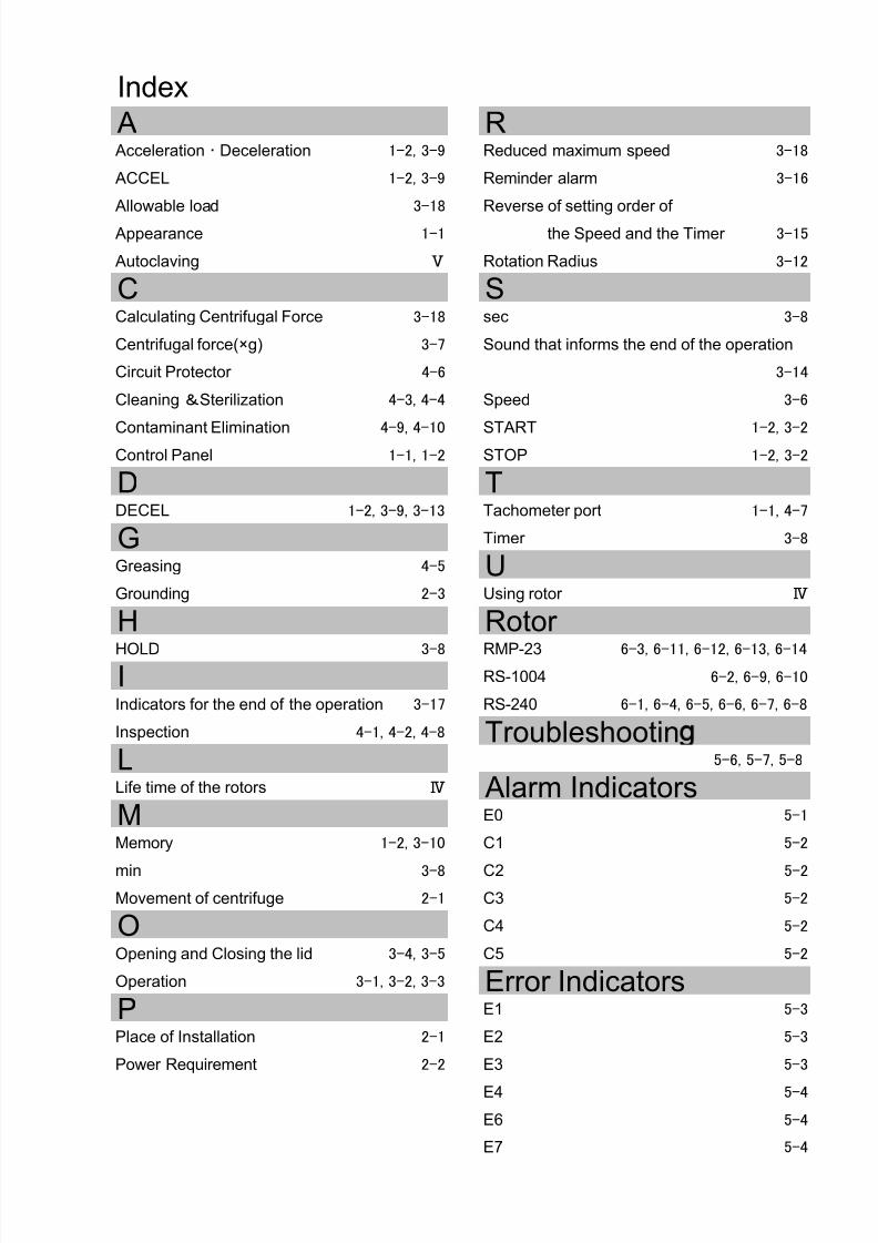
7/25/2019 Kubota 2420
http://slidepdf.com/reader/full/kubota-2420 66/70
Index
Acceleration ・ Deceleration 1-2, 3-9 Reduced maximum speed 3-18
ACCEL 1-2, 3-9 Reminder alarm 3-16
Allowable load 3-18 Reverse of setting order of
Appearance 1-1 the Speed and the Timer 3-15
Autoclaving Ⅴ Rotation Radius 3-12
Calculating Centrifugal Force 3-18 sec 3-8
Centrifugal force(×g) 3-7 Sound that informs the end of the operation
Circuit Protector 4-6 3-14
Cleaning &Sterilization 4-3, 4-4 Speed 3-6
Contaminant Elimination 4-9, 4-10
START 1-2, 3-2
Control Panel 1-1, 1-2 STOP 1-2, 3-2
DECEL 1-2, 3-9, 3-13 Tachometer port 1-1, 4-7
Timer 3-8
Greasing 4-5
Grounding 2-3 Using rotor Ⅳ
HOLD 3-8 RMP-23 6-3, 6-11, 6-12, 6-13, 6-14
RS-1004 6-2, 6-9, 6-10
Indicators for the end of the operation 3-17 RS-240 6-1, 6-4, 6-5, 6-6, 6-7, 6-8
Inspection 4-1, 4-2, 4-8
5-6, 5-7, 5-8
Life time of the rotors Ⅳ
E0 5-1
Memory 1-2, 3-10 C1 5-2
min 3-8 C2 5-2
Movement of centrifuge 2-1 C3 5-2
C4 5-2
Opening and Closing the lid 3-4, 3-5 C5 5-2
Operation 3-1, 3-2, 3-3
E1 5-3
Place of Installation 2-1 E2 5-3
Power Requirement 2-2 E3 5-3
E4 5-4
E6 5-4
E7 5-4
R
L
M
A
P
S
T
Troubleshootin
G
D
C
U
Rotor
Alarm Indicators
Error Indicators
O
H
I
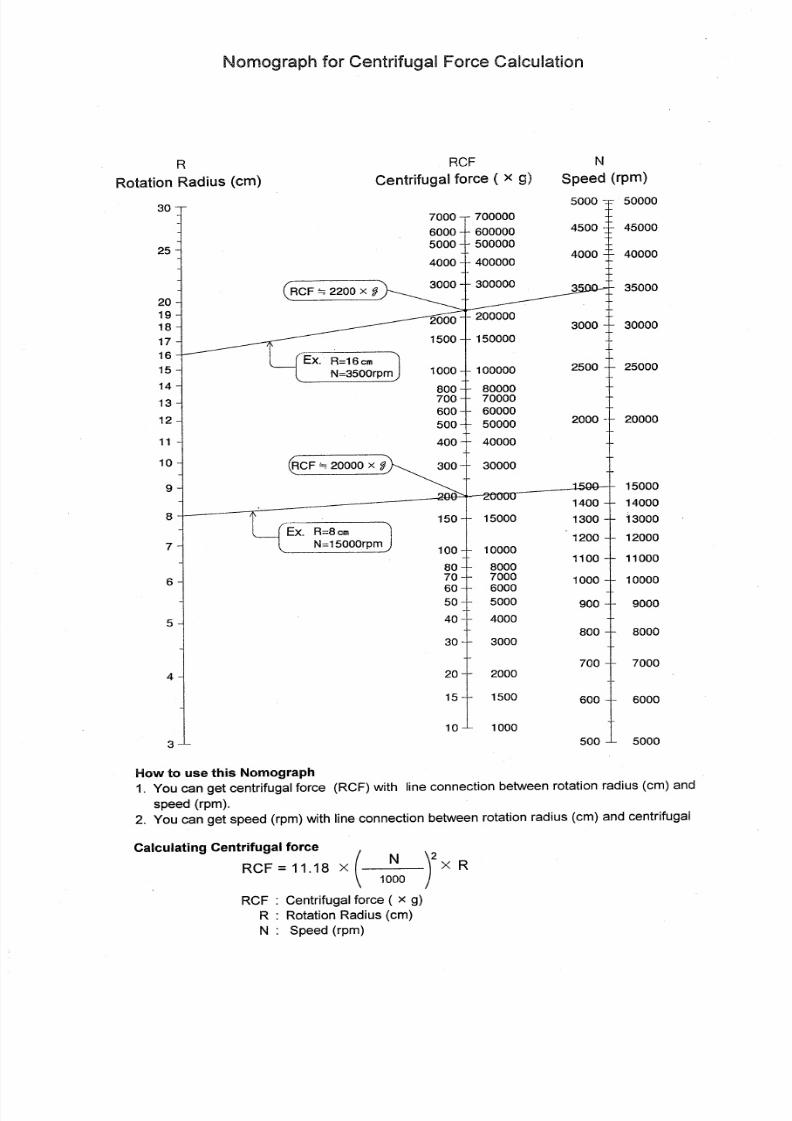
7/25/2019 Kubota 2420
http://slidepdf.com/reader/full/kubota-2420 67/70
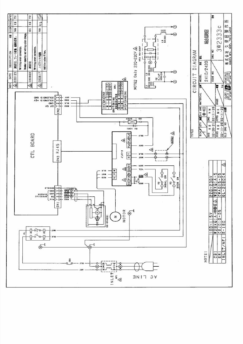
7/25/2019 Kubota 2420
http://slidepdf.com/reader/full/kubota-2420 68/70
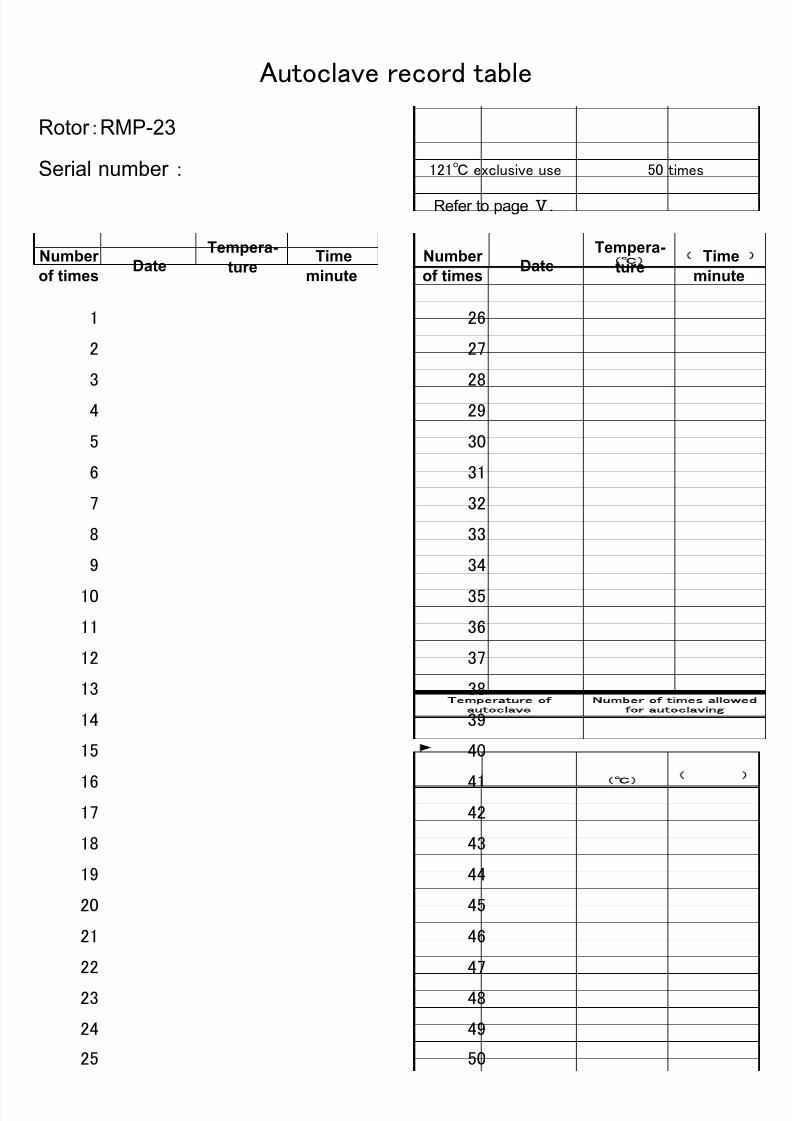
7/25/2019 Kubota 2420
http://slidepdf.com/reader/full/kubota-2420 69/70
Autoclave record table
Refer to page Ⅴ.
Number
of times Date
Tempera-
ture
(℃)
Time
(minute )
Number
of times Date
Tempera-
ture
(℃)
Time
(minute )
1 26
2 27
3 28
4 29
5 30
6 31
7 32
8 33
9 34
10 35
11 36
12 37
13 38
14 39
15 40
16 4117 42
18 43
19 44
20 45
21 46
22 47
23 48
24 49
25 50
121℃ exclusive use 50 timesSerial number :
Rotor :RMP-23 umbe r of times al lowed
for autoclaving
Temperature of
autoclave
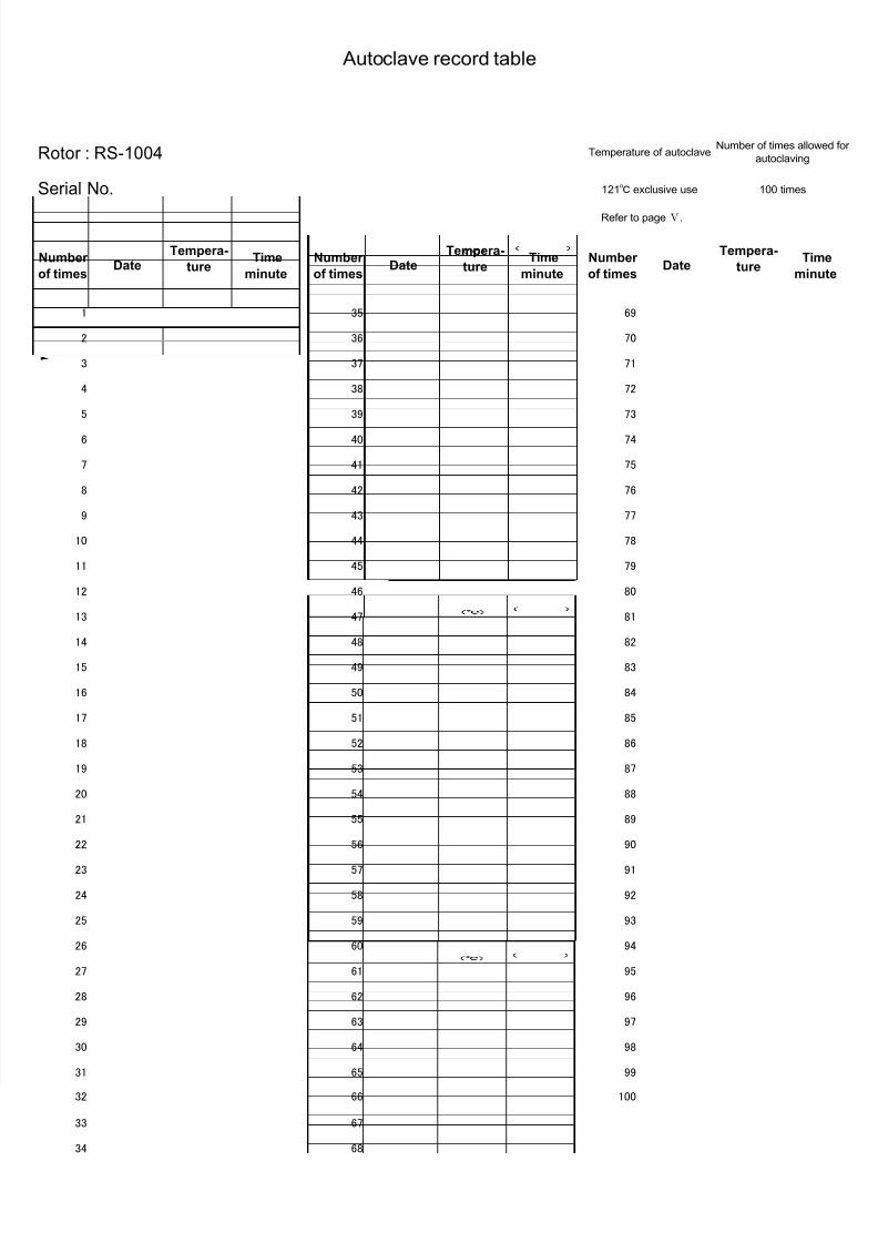
7/25/2019 Kubota 2420
http://slidepdf.com/reader/full/kubota-2420 70/70
Autoclave record table
Rotor : RS-1004
Refer to pageⅤ.
Number
of times Date
Tempera-
ture
)
Time
minute )
Number
of times Date
Tempera-
ture
)
Time
minute )
Number
of times Date
Tempera-
ture
)
Time
minute )
1 35 69
2 36 70
3 37 71
4 38 72
5 39 73
6 40 74
7 41 75
8 42 76
9 43 77
10 44 78
11 45 79
12 46 80
13 47 81
14 48 82
15 49 83
16 50 84
17 51 85
18 52 86
19 53 87
20 54 88
21 55 89
22 56 90
23 57 91
24 58 92
25 59 93
26 60 94
27 61 95
Temperature of autoclave
121℃ exclusive useSerial No.
Number of times allowed for
autoclaving
100 times

![Catálogo Kubota Miniexcavadoras K008-3€¦ · qvfefo hvbsebstf fo vo dpnqbsujnfoup tjuvbep fo fm sftqbmep efm btjfoup 3xqwrv gh l]dplhqwr-pt usft qvoupt ef j[bnjfoup ibdfo gµdjm](https://static.fdocuments.pl/doc/165x107/5ea0cf17b56e5537f87036c1/catlogo-kubota-miniexcavadoras-k008-3-qvfefo-hvbsebstf-fo-vo-dpnqbsujnfoup-tjuvbep.jpg)