
KOVIAN NICE SK 2016/17
83
-
Upload
kovian-sro -
Category
Documents
-
view
284 -
download
33
description
Katalóg produktov NICE 2016/17.
Transcript of KOVIAN NICE SK 2016/17
167
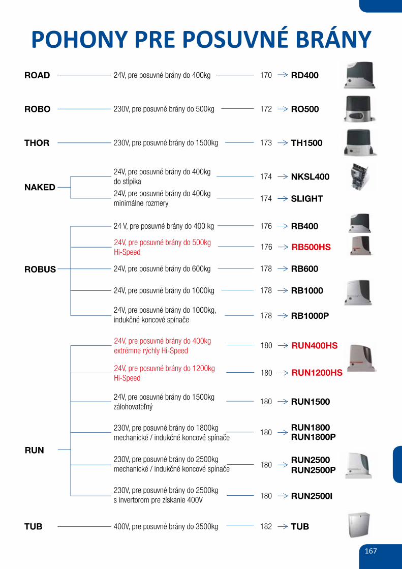
POHONY PRE POSUVNÉ BRÁNYROAD 24V, pre posuvné brány do 400kg RD400
ROBO
THOR
NAKED
170
ROAD400
ROBO500
Siłownik elektromechaniczny do bram przesuwnych
o ciężarze do 400 kg.
Sprzedawany w zestawach.
wbudowana modułowa elektronika, tylko trzyPraktyczny:
przyciski programowania, wyjmowane wtyczki do podłączeń
urządzeń dodatkowych (np. fotokomórek).
Wbudowana centrala sterująca RBA4.
radioodbiornik 433.92 MHz (multikod) zintegrowany z płytąUniwersalny:
elektroniki, z możliwością wgrania pilotów FLO/FLOR//ONE/SMILO/NICEWAY/INTI.
Pamięć 150 pilotów. Pierwszy wgrany pilot określa
drogę radiową, na której będzie pracować radioodbiornik.
prędkość, siła i pauza - mogą być regulowane, diody LEDZalety:
sygnalizują włączone funkcje.
Kod
RD400KCE zestaw do bram przesuwnych o ciężarze bramy do 400 kg, siłownik samohamowny z wbudowaną centralą sterującą RBA4,
radioodbiornik 433,92 MHz zintegrowany z płytą elektroniki, z możliwością wgrania pilotów FLO/FLOR//ONE/SMILO/NICEWAY/INTI,
2 piloty dwukanałowe FLO2RE
cena netto cena brutto
1 600,00 1 968,00
Inteligentny: siłownik w czasie programowania automatycznie
zapamiętuje położenia krańcowe bramy.
stała kontrola podłączonychAutodiagnoza za pomocą lampy:
urządzeń, lampa sygnalizuje niesprawne działanie systemu
ilością mignięć określa typ błędu.
amperometryczny system wykrywania przeszkody,Bezpieczny:
zwolnienie podczas zamykania i łagodny start przy otwieraniu.
Fotokomórki typu BF/MOF/FK/F210/FT210.
122| OFERTA SPECJALNA
THOR1500
zestaw do bram przesuwnych o ciężarze bramy do 1500 kg, siłownik samohamowny z wbudowaną centralą sterującą ROA37,
radioodbiornik 433,92 MHz zintegrowany z płytą elektroniki, z możliwością wgrania pilotów ,FLO/FLOR//ONE/SMILO/NICEWAY/INTI
2 piloty dwukanałowe FLO2RE
TH1500KCE 2 706,002 200,00
Zasilanie/Zasilanie silnika
Prąd pobierany
Moc pobierana
Wbudowany kondensator
Stopień zabezpieczenia
Prędkość
Max. siła
Max. ciężar bramy
Temperatura pracy
Intensywność pracy
Ciężar
Parametry
(V)
(A)
(W)
(uF)
(IP)
(m/s)
(N)
(kg)
( C min/max)o
(cykle/h)
(kg)
RD400 RO500 TH1500
230/24
1,1
210
-
44
0.25
400
400
-20 ÷ +50
20
8
230/230
1,7
400
12
44
0.18
500
500
-20 ÷ +50
9
8
230/230
1,8
400
14
44
0.16
800
1500
-20 ÷ +50
16
13
[3 x 1.5 mm ] zasilanie2[legenda]
[4 x 0.5 mm ] linia foto (RX)2
[4 x 1.0 mm ] zamek, przycisk2
[2 x 0.75 mm ] lampa2
[Rg58] antena
[2 x 0.5 mm ] linia foto (TX)2
Kod
SCHEMAT INSTALACJI
230V, pre posuvné brány do 500kg 172 RO500
230V, pre posuvné brány do 1500kg 173 TH1500
24V, pre posuvné brány do 400kgdo stĺpika
174 NKSL400
ROBUS 24V, pre posuvné brány do 600kg 178 RB600
24 V, pre posuvné brány do 400 kg 176 RB400
24V, pre posuvné brány do 1000kg 178 RB1000
24V, pre posuvné brány do 1000kg,indukčné koncové spínače 178 RB1000P
RUN
230V, pre posuvné brány do 1800kgmechanické / indukčné koncové spínače
180RUN1800
24V, pre posuvné brány do 1500kgzálohovateľný
180 RUN1500
230V, pre posuvné brány do 2500kgmechanické / indukčné koncové spínače 180
RUN2500P
230V, pre posuvné brány do 2500kgs invertorom pre získanie 400V 180 RUN2500I
TUB 400V, pre posuvné brány do 3500kg 182 TUB
SLIGHT
RUN2500
24V, pre posuvné brány do 400kgminimálne rozmery
174
24V, pre posuvné brány do 500kgHi-Speed
176 RB500HS
RUN1800P
24V, pre posuvné brány do 1200kgHi-Speed
180 RUN1200HS
24V, pre posuvné brány do 400kgextrémne rýchly Hi-Speed
180 RUN400HS
168
X
330 195
85
277
3
9
1 2
D
8
3
7
10
E
CA
BFC
E
4
56
11
330
192
25÷35
192
330 0÷50
0÷50
0÷10
0÷10
1
2
3 4 5
6 7
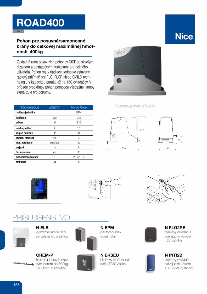
ROAD400
Pohon pre posuvné/samonosnébrány do celkovej maximálnej hmot-nosti 400kg
Základná rada posuvných pohonov NICE so skvelým dizajnom a dostatočnými funkciami pre bežného užívateľa. Pohon má v riadiacej jednotke vstavaný rádiový prijímač pre FLO, FLOR alebo SMILO tech-nologiu s kapacitou pamäti až na 150 ovladačov. V prípade problémov pohon pomocou výstražnej lampy signalizuje typ poruchy.
TECHNICKÉ ÚDAJE JEDNOTKA POHON: RD400
riadiaca jednotka RBA4
napájenie Vac 230
príkon W 210
prúdový odber A 1,1
stupeň ochrany IP 44
krútiaci moment Nm 12
max. zaťaženie cykly/den 50
prejezd m 8
čas otvorenia sec. 35
prevádzková teplota °C -20 až +50
hmotnosť kg 8
PRÍSLUŠENSTVON ELBvýstražná lampa 12Vso vstavanou anténou
CREM-Phrebeň plastový s kovo-vým jadrom do 600kg, 1000mm, 6 úchytov
N EPMpár fotobuniekdosah 30m
N EKSEUhliníkový kľúčový spí-nač, „FAB“ vložka
N FLO2REdiaľkový ovládač s plávajúcim kódom 433,92MHz
N INTI2Bdiaľkový ovládač s plávajúcim kódom 433,92MHz, modrý
Rozmery pohonu RD400
XII
16 17
18 19
20
21 22
23 24
Aanwijzingen en aanbevelingen bestemd voor de gebruiker van de reductiemotor ROAD
Proficiat met de keuze van een product Nice voor uwautomatisering! Nice S.p.a. produceert componenten voor het automatiseren vanpoorten, deuren, rolpoorten, rolluiken en zonwering: reductiemotors, besturingseen-heden, afstandsbedieningen, waarschuwingslichten, fotocellen en accessoires.Nice gebruikt uitsluitend kwaliteitsmateriaal en -bewerkingen, en geroepen als zijzich voelt, zoekt ze naar vernieuwende oplossingen die haar apparaten - verzorgd inde technische esthetische en ergonomische aspecten - zo gebruiksvriendelijkmogelijk maakt:in het uitgebreide programma van Nice zal uw installateur ongetwij-feld dat product uitgekozen hebben dat het meest aan uw eisen beantwoordt. Niceis echter niet de fabrikant van uw automatiseringsinstallatie, die daarentegen hetresultaat is van analyse, evaluatie, keuze van materialen, en het aanleggen daarvandoor uw vertrouwensinstallateur. Elke automatisering is uniek en alleen uw installa-teur bezit de ervaring en het vakmanschap dat nodig is om een installatie volgensuw verlangens uit te voeren, veilig en betrouwbaar in de tijd, en vooral volgens deregelen der kunst, dat wil zeggen conform de geldende voorschriften. Een automa-tiseringsinstallatie is een groot gemak, een waardevol veiligheidssysteem en kanmet een beetje aandacht tot in lengte van dagen duren. Ook al beantwoordt deautomatisering in uw bezit aan het in normen en wetten voorgeschreven veiligheids-niveau, dit sluit niet uit dat er een “restrisico” bestaat, dat wil zeggen de mogelijkheiddat er gevaarlijke situaties kunnen ontstaan, die gewoonlijk te wijten zijn aan onver-antwoordelijk of zelfs verkeerd gebruik; hierom willen wij u enige adviezen geven hoeu met de automatisering dient om te gaan teneinde elk eventueel probleem te voor-komen:
• Voordat u de automatisering voor de eerste maal gaat gebruiken, ishet raadzaam u door de installateur te laten uitleggen waar de restrisico's ont-staan, en enkele minuten van uw tijd te besteden aan het lezen van deze handlei-ding met aanwijzingen en aanbevelingen voor de gebruiker die deinstallateu u overhandigd heeft. Bewaar deze handleiding voor eventuele toe-komstige twijfels en geef haar aan een eventuele nieuwe eigenaar van de auto-matisering.
• Uw automatisering is een machine die getrouwelijk uw instructiesopvolgt; onverantwoordelijk en oneigenlijk gebruik kan maken dat het eengevaarlijke machine wordt: laat de automatisering niet werken als er zich mensen,dieren of zaken binnen haar bereik bevinden.
• Kinderen: een automatiseringsinstallatie biedt een hoge graad van veiligheid,doordat ze met haar beveiligingssystemen de manoeuvre bij aanwezigheid vanmensen of zaken onderbreekt en altijd een voorspelbare en veilige activeringgarandeert. Het is in ieder geval verstandig kinderen te verbieden in de buurt vande installatie te spelen en de afstandsbedieningen buiten hun bereik te houden omte voorkomen dat de installatie per ongeluk in werking komt: het is geen speel-goed!
• Storingen: Zodra u constateert dat de automatiseringsinstallatie niet werkt zoalsze dat zou moeten doen, dient u de stroomtoevoer naar de installatie te onderbre-ken en haar handmatig te ontgrendelen. Probeer niet zelf te repareren, maar roepde hulp van uw vertrouwensinstallateur in: intussen kan de installatie werken alseen niet geautomatiseerde toegang, wanneer u de reductiemotor op de hieronderbeschreven manier ontgrendeld hebt.
• Onderhoud: Zoals elke machine heeft uw installatie periodiek onderhoud nodigom haar zo lang mogelijk en geheel veilig te laten werken.Stel met uw installateureen onderhoudsplan met periodieke frequentie op; Nice raadt bij normaal gebruikbij een woning een onderhoudsbezoek om het half jaar aan, maar dit tijdsbestekkan variëren in functie van een meer of minder intensief gebruik. Alle controle-,onderhouds- of reparatiewerkzaamheden mogen uitsluitend door gekwalificeerdpersoneel worden uitgevoerd.
• Ook al bent u van mening dit te kunnen doen, breng geen wijzigingen aan deinstallatie en de programmerings- en afstellingsparameters van uw automatise-ringsinstallatie aan: uw installateur is aansprakelijk.
• De opleveringstest, de periodieke nderhoudswerkzaamheden en de eventuelereparatiewerkzaamheden dienen gedocumenteerd te worden door wie die uitvoerten de documenten dienen door de eigenaar van de installatie bewaard te worden.De enige werkzaamheden die de gebruiker regelmatig kan en moet uitvoerenzijn het reinigen van de glaasjes van de fotocellen en het verwijderen van bladerenen stenen die het automatisme in diens werking kunnen belemmeren. Om te voor-komen dat iemand de deur in beweging kan bregen dient u eraan te denken voor-dat u dit gaat doen het automatisme (zoals verderop beschreven) te ontgren-delen en voor het schoonmaken alleen een enigszins vochtige in water gedrenktedoek te gebruiken.
• Afvalverwerking: Als de automatisering niet meer gebruikt kan worden, dient uzich ervan te vergewissen dat de sloop daarvan door gekwalificeerd personeelwordt uitgevoerd en dat het materiaal volgens de plaatselijk geldende voorschrif-ten wordt hergebruikt of naar de afvalverwerking wordt gezonden.
• In geval van defecten of stroomuitval: In afwachting van het bezoek van uwinstallateur, (of het terugkeren van de elektrische stroom als de installatie niet vanbufferbatterijen voorzien is), mag de installatie gebruikt worden als elke andereniet-geautomatiseerde toegang. Hiertoe dient u de automatisering handmatig teontgrendelen: aan deze handeling, die de enige is die de gebruiker van de auto-matisering mag uitvoeren, heeft Nice bijzonder veel aandacht besteed om u altijdeen maximum aan gebruiksvriendelijkheid te garanderen, zonder dat u gereed-schap moet gebruiken of fysieke kracht moet aanwenden.
Ontgrendeling en handmatige manoeuvre: voordat u dit gaat doen dient uerop te letten dat ontgrendeling alleen kan plaatsvinden wanneer de vleugel stil staat.
Voor vergrendeling: doe hetzelfde, maar dan in omgekeerde volgorde.
Bediening wanneer de veiligheidsinrichtingen buiten gebruik zijn: indiende veiligheidsinrichtingen van de poort niet correct mochten functioneren, kunt u depoort toch bedienen.• Activeer de bediening van de poort (met de afstandsbediening, sleutelschakelaar,
etc.); als alles in orde is zal de poort normaal open of dicht gaan, anders zal hetknipperlicht enkele malen knipperen en zal de manoeuvre niet van start gaan (hetaantal malen dat het knipperlicht knippert heeft te maken met de reden waaromde manoeuvre niet van start kan gaan).
• In dit geval moet u de bedieningsinrichting binnen 3 seconden nogmaals active-ren en geactiveerd houden.
• Na ongeveer 2s komt de poort in beweging en wel in de modus “iemand aanwe-zig”, d.w.z. zolang de bedieningsinrichting geactiveerd blijft, beweegt de poort;zodra de bedieningsinrichting losgelaten wordt, stopt de poort.
Wanneer de beveiligingen buiten gebruik zijn, moet het automatisme zosnel mogelijk gerepareerd worden.
Vervanging van de batterij van de afstandsbediening: als uw afstandsbe-diening na enige tijd minder lijkt te werken, of helemaal niet te werken, zou dit een-voudigweg kunnen komen omdat de batterij leeg is (afhankelijk van het type daarvankan dat na verschillende maanden of na twee/drie jaar zijn). U kunt dit zien doordathet waarschuwingslampje dat de doorzending bevestigt, zwak brandt, of helemaalniet brandt, of slechts eventjes brandt. Voordat u zich tot de installateur wendt kuntu proberen de batterij van een andere zender die wèl werkt, in te zetten: als dit deoorzaak van de storing is, behoeft u alleen maar een nieuwe batterij van hetzelfdetype in te zetten.
Let op: De batterijen bevatten vervuilende stoffen: gooi ze niet met het gewone hui -svuil weg, maar gebruik de methoden die in de plaatselijke voorschriften voorzien zijn.
Bent u tevreden? Indien u in uw huis nog een nieuwe automatiseringsinstallatiezou willen, kunt u zich, wanneer u zich tot dezelfde installateur en Nice wendt, vande adviezen van een specialist en de meest geavanceerde producten op de marktverzekeren. Het resultaat: een automatisering die het best functioneert en een maxi-male compatibiliteit met de andere automatiseringen.Wij bedanken u voor het lezen van deze aanbevelingen, en wij hopen dat u veel ple-zier van uw nieuwe installatie zult hebben: wend u voor elke vraag, nu of in de toe-komst, vol vertrouwen tot uw installateur.
1 Verschuif het plaatje dat het slot be-schermt
2 Steek de sleutel in het slot en draaidie met de wijzers van de klok om
3 Trek aan de ontgrendelingshand-greep
4 Verplaats de vleugel handmatig
VIII
NL
24V
169
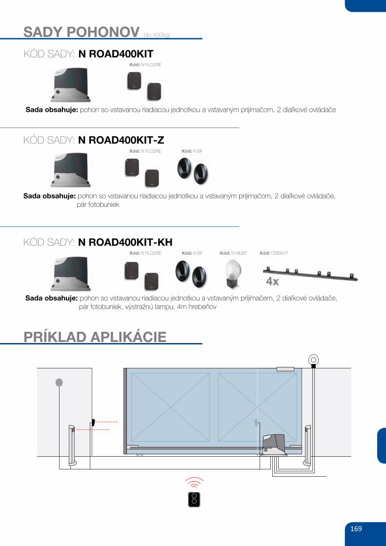
SADY POHONOV (do 400kg)
KÓD SADY: N ROAD400KIT
Sada obsahuje: pohon so vstavanou riadiacou jednotkou a vstavaným prijímačom, 2 diaľkové ovládače
Kód: N FLO2RE
KÓD SADY: N ROAD400KIT-Z
Sada obsahuje: pohon so vstavanou riadiacou jednotkou a vstavaným prijímačom, 2 diaľkové ovládače, pár fotobuniek
Kód: N FLO2RE Kód: N BF
KÓD SADY: N ROAD400KIT-KH
Sada obsahuje: pohon so vstavanou riadiacou jednotkou a vstavaným prijímačem, 2 diaľkové ovládače, pár fotobuniek, výstražnú lampu, 4m hrebeňov
Kód: N FLO2RE Kód: N BF Kód: N MLBT Kód: CREM-P
4x
PRÍKLAD APLIKÁCIE
170
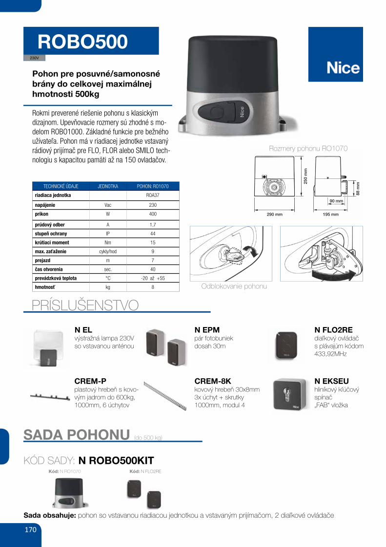
ROBO500Pohon pre posuvné/samonosné brány do celkovej maximálnejhmotnosti 500kg
Rokmi preverené riešenie pohonu s klasickým dizajnom. Upevňovacie rozmery sú zhodné s mo-delom ROBO1000. Základné funkcie pre bežného užívateľa. Pohon má v riadiacej jednotke vstavaný rádiový prijímač pre FLO, FLOR alebo SMILO tech-nologiu s kapacitou pamäti až na 150 ovladačov.
EN
8 – English
MANUALLY RELEASING OR LOCKING THE GEARMOTORThe gearmotor is equipped with a mechanical system that enables manu-al opening and closing of the gate.These manual operations must be performed in the event of a power fail-ure or system malfunctions. In the latter case, use of the release mecha-nism may be useful also to check whether the fault is linked to the mecha-nism itself (e.g. it may be incorrectly tightened).To manually release the gearmotor, use the release key supplied as follows:01. Slide the lock cover backwards;02. Insert the key in the relative release pin;03. Turn the key clockwise through 90° and pull the handle towards you;
04. At this point the gate leaf can be moved manually to the required posi-tion.
05. To restore normal automation operation, close the handle, turn thekey anti-clockwise on the release pin and manually move the gate leafuntil you hear the leaf engage mechanically with the drive mechanism.
06. Then remove the key from the release pin and store in a safe place.
IMPORTANT – This instruction sheet contains important informationregarding safety; take care to read all instructions before using theproduct. Keep this manual in a safe place to enable future use.
SAFETY WARNINGS AND PRECAUTIONSNEVER touch parts of the automation while the gate is moving!• Before using the automation for the first time, take care to read this oper-ation manual provided by the automation installer. Also ensure that you arefully informed of all origins of residual risks.• Keep the manual for consultation when in doubt and ensure supply tonew owners of the automation.• Your automation is a machine that performs commands imparted by theuser; negligent or improper use may constitute a hazard. Never activateautomation controls if persons, animals or objects are present in the oper-ating range.• Children: this automation system guarantees a high level of safety,using special detection devices to prevent movement in the presenceof persons or objects . thereby guaranteeing constant foreseeableand safe activation. However, it is advisable to ensure that childrendo not play in the vicinity of the automation. To avoid inadvertent acti-vation, and remote controls should always be kept out of reach. (thetransmitter is not a toy!).• Check the automation frequently to detect possible imbalance, signs ofwear or damage. Suspend use immediately if maintenance is required.• Periodically check correct operation of the photocells and perform thescheduled maintenance at least every six months.• Photocells do not constitute actual safety devices, but safety aids. Theyare designed using highly reliable technology, but in extreme conditionsmay be subject to malfunctions or potential faults. CAUTION!– In certaincases these faults are not immediately evident.Never pass the transit area while the gate is moving!• If any anomalous condition is noted on the automation, disconnect thepower supply from the system immediately. Never attempt to repair theautomation alone; contact your local installer for assistance. In the mean-time the system can be used with manual Opening and Closing by manu-ally releasing the gearmotors as described in this manual.• In the event of a power failure, on restoral of power the first manoeuvrecommand will be executed at low speed, regardless of the type of speedset.• Even if you possess the skills, never modify the system or automationprogramming and adjustment parameters: This is the responsibility of theautomation installer.• Testing, periodic maintenance and any repairs must be documented bythe person performing the operations and the relative documents must bekept by the system owner.• At the end of the automation’s lifetime, ensure that it is disposed by qual-ified personnel and that the materials are recycled or scrapped accordingto current standards in the place of use.
OPERATION MANUAL(to deliver to the automation user)
PRÍSLUŠENSTVO
EN
8 – English
MANUALLY RELEASING OR LOCKING THE GEARMOTORThe gearmotor is equipped with a mechanical system that enables manu-al opening and closing of the gate.These manual operations must be performed in the event of a power fail-ure or system malfunctions. In the latter case, use of the release mecha-nism may be useful also to check whether the fault is linked to the mecha-nism itself (e.g. it may be incorrectly tightened).To manually release the gearmotor, use the release key supplied as follows:01. Slide the lock cover backwards;02. Insert the key in the relative release pin;03. Turn the key clockwise through 90° and pull the handle towards you;
04. At this point the gate leaf can be moved manually to the required posi-tion.
05. To restore normal automation operation, close the handle, turn thekey anti-clockwise on the release pin and manually move the gate leafuntil you hear the leaf engage mechanically with the drive mechanism.
06. Then remove the key from the release pin and store in a safe place.
IMPORTANT – This instruction sheet contains important informationregarding safety; take care to read all instructions before using theproduct. Keep this manual in a safe place to enable future use.
SAFETY WARNINGS AND PRECAUTIONSNEVER touch parts of the automation while the gate is moving!• Before using the automation for the first time, take care to read this oper-ation manual provided by the automation installer. Also ensure that you arefully informed of all origins of residual risks.• Keep the manual for consultation when in doubt and ensure supply tonew owners of the automation.• Your automation is a machine that performs commands imparted by theuser; negligent or improper use may constitute a hazard. Never activateautomation controls if persons, animals or objects are present in the oper-ating range.• Children: this automation system guarantees a high level of safety,using special detection devices to prevent movement in the presenceof persons or objects . thereby guaranteeing constant foreseeableand safe activation. However, it is advisable to ensure that childrendo not play in the vicinity of the automation. To avoid inadvertent acti-vation, and remote controls should always be kept out of reach. (thetransmitter is not a toy!).• Check the automation frequently to detect possible imbalance, signs ofwear or damage. Suspend use immediately if maintenance is required.• Periodically check correct operation of the photocells and perform thescheduled maintenance at least every six months.• Photocells do not constitute actual safety devices, but safety aids. Theyare designed using highly reliable technology, but in extreme conditionsmay be subject to malfunctions or potential faults. CAUTION!– In certaincases these faults are not immediately evident.Never pass the transit area while the gate is moving!• If any anomalous condition is noted on the automation, disconnect thepower supply from the system immediately. Never attempt to repair theautomation alone; contact your local installer for assistance. In the mean-time the system can be used with manual Opening and Closing by manu-ally releasing the gearmotors as described in this manual.• In the event of a power failure, on restoral of power the first manoeuvrecommand will be executed at low speed, regardless of the type of speedset.• Even if you possess the skills, never modify the system or automationprogramming and adjustment parameters: This is the responsibility of theautomation installer.• Testing, periodic maintenance and any repairs must be documented bythe person performing the operations and the relative documents must bekept by the system owner.• At the end of the automation’s lifetime, ensure that it is disposed by qual-ified personnel and that the materials are recycled or scrapped accordingto current standards in the place of use.
OPERATION MANUAL(to deliver to the automation user)
SADA POHONU (do 500 kg)
KÓD SADY: N ROBO500KIT
ROAD400
ROBO500
Siłownik elektromechaniczny do bram przesuwnych
o ciężarze do 400 kg.
Sprzedawany w zestawach.
wbudowana modułowa elektronika, tylko trzyPraktyczny:
przyciski programowania, wyjmowane wtyczki do podłączeń
urządzeń dodatkowych (np. fotokomórek).
Wbudowana centrala sterująca RBA4.
radioodbiornik 433.92 MHz (multikod) zintegrowany z płytąUniwersalny:
elektroniki, z możliwością wgrania pilotów FLO/FLOR//ONE/SMILO/NICEWAY/INTI.
Pamięć 150 pilotów. Pierwszy wgrany pilot określa
drogę radiową, na której będzie pracować radioodbiornik.
prędkość, siła i pauza - mogą być regulowane, diody LEDZalety:
sygnalizują włączone funkcje.
Kod
RD400KCE zestaw do bram przesuwnych o ciężarze bramy do 400 kg, siłownik samohamowny z wbudowaną centralą sterującą RBA4,
radioodbiornik 433,92 MHz zintegrowany z płytą elektroniki, z możliwością wgrania pilotów FLO/FLOR//ONE/SMILO/NICEWAY/INTI,
2 piloty dwukanałowe FLO2RE
cena netto cena brutto
1 600,00 1 968,00
Inteligentny: siłownik w czasie programowania automatycznie
zapamiętuje położenia krańcowe bramy.
stała kontrola podłączonychAutodiagnoza za pomocą lampy:
urządzeń, lampa sygnalizuje niesprawne działanie systemu
ilością mignięć określa typ błędu.
amperometryczny system wykrywania przeszkody,Bezpieczny:
zwolnienie podczas zamykania i łagodny start przy otwieraniu.
Fotokomórki typu BF/MOF/FK/F210/FT210.
Kód: N RO1070 Kód: N FLO2RE
1
2
3
4
5
6
290 mm 195 mm
88 m
m250
mm
90 mm
D3
D2 D2D6D7 D7D1
D4
D5 D5
TECHNICKÉ ÚDAJE JEDNOTKA POHON: RO1070
riadiaca jednotka ROA37
napájenie Vac 230
príkon W 400
prúdový odber A 1,7
stupeň ochrany IP 44
krútiaci moment Nm 15
max. zaťaženie cykly/hod 9
prejazd m 7
čas otvorenia sec. 40
prevádzková teplota °C -20 až +55
hmotnosť kg 8
N ELvýstražná lampa 230Vso vstavanou anténou
N EPMpár fotobuniekdosah 30m
CREM-8Kkovový hrebeň 30x8mm3x úchyt + skrutky1000mm, modul 4
N FLO2REdiaľkový ovládačs plávajúm kódom433,92MHz
N EKSEUhliníkový kľúčový spínač „FAB“ vložka
Sada obsahuje: pohon so vstavanou riadiacou jednotkou a vstavaným prijímačom, 2 diaľkové ovládače
230V
Odblokovanie pohonu
CREM-Pplastový hrebeň s kovo-vým jadrom do 600kg, 1000mm, 6 úchytov
Rozmery pohonu RO1070

171
THOR1500Pohon pre posuvné/samonosné brány do celkovej max. hmotnosti 1500kg
Cenovo bezkonkurenčný nástupca predchádzajúcej verzie pohonu THOR s klasickým dizajnom. Upevňo-vacie rozmery sú zhodné s modelom TH1551. Po-hon je vybavený základnými funkciami pre bežného užívateľa. V riadiacej jednotke je integrovaný rádiový prijímač pre FLO, FLOR alebo SMILO technológiu s kapacitou pamäti až na 150 ovladačov.
10
A
B
C
C
D
6 7
8 9
1-2 mm
PRÍSLUŠENSTVO
BLOCCARE O SBLOCCARE MANUALMENTE IL MOTORIDUT-TOREIl motoriduttore è dotato di un sistema meccanico che consente di aprire echiudere il cancello manualmente.Queste operazioni manuali devono essere eseguite nei casi di mancanzadi corrente elettrica o di anomalie di funzionamento. In quest’ultimo caso,l’uso del meccanismo di sblocco può essere utile anche per verificare se ilguasto dipende dal meccanismo stesso (ad esempio potrebbe esserestretto male).Per sbloccare manualmente il motoriduttore, utilizzare la chiave di sbloccoin dotazione nel modo seguente:01. Ruotare il copriserratura;02. Inserire la chiave nell’apposito perno di sblocco;03. Ruotare di 90° la chiave in senso orario e, tirare verso di se la maniglia;
04. A questo punto sarà possibile muovere manualmente l’anta del can-cello nella posizione desiderata;
05. Per ripristinare la funzionalità dell’automatismo, richiudere la manigliae, ruotare in senso antiorario l’apposita chiave sul perno di sblocco emuovere manualmente l’anta fino a quando si sente il rumore mecca-nico di aggancio dell’anta al meccanismo di traino;
06. Infine, togliere la chiave dal perno di sblocco e conservarla.
IT
8 – Italiano
IMPORTANTE – Questo foglio d’istruzioni contiene importanti infor-mazioni riguardanti la sicurezza; è necessario leggere tutte le istru-zioni prima di utilizzare il prodotto. Conservare con cura questomanuale anche per utilizzi futuri.
AVVERTENZE E PRECAUZIONI PER L’USOÈ assolutamente vietato toccare parti dell’automazione mentre ilcancello è in movimento!• Prima di usare per la prima volta l’automazione, dedicate qualche minu-to alla lettura del presente manuale per l’uso, consegnatovi da chi hainstallato l’automazione. Inoltre, fatevi spiegare da questo l’origine deirischi residui.• Conservate il presente manuale per ogni dubbio futuro e consegnateload un eventuale nuovo proprietario dell’automazione.• La vostra automazione è un macchinario che esegue fedelmente i vostricomandi; un uso incosciente ed improprio può farlo diventare pericoloso.Non comandate il movimento dell’automazione se nel suo raggio di azionesi trovano persone, animali o cose.• Bambini: questo impianto di automazione garantisce un alto gra-do di sicurezza, impedendo con i suoi sistemi di rilevazione il movi-mento in presenza di persone o cose. Inoltre, garantisce un’attiva-zione sempre prevedibile e sicura. In ogni caso, è prudente vietareai bambini di giocare in prossimità dell’automazione. Per evitareattivazioni involontarie dell’automazione non lasciare i trasmettito-ri alla loro portata (il trasmettitore non è un gioco!).• Controllate frequentemente l’automazione alla ricerca di eventuali segnidi usura, danni o sbilanciamento. Sospendere immediatamente l’uso se ènecessaria una manutenzione.• Verificare periodicamente il corretto funzionamento delle fotocellule e fareseguire almeno ogni 6 mesi i controlli di manutenzione previsti.• Le fotocellule non sono un dispositivo di sicurezza ma soltanto un di spo-sitivo ausiliario alla sicurezza. Queste sono costruite con tecnologia adaltissima affidabilità ma possono, in situazioni estreme, subire malfunzio-namenti o addirittura guastarsi. Attenzione! – In certi casi il guastopotrebbe non essere subito evidente.È assolutamente vietato transitare mentre il cancello è in movi-mento!• Non appena notate qualunque comportamento anomalo da parte del-l’automazione, per sicurezza togliere l’alimentazione elettrica all’impianto.Non tentare da soli nessuna riparazione ma richiedere l’intervento delvostro installatore di fiducia. Nel frattempo l’impianto potrà funzionare conApertura e Chiusura manuale, sbloccando manualmente i motoriduttoricome descritto in questo manuale.• In caso di mancanza dell’energia elettrica, al ripristino della corrente laprima manovra comandata verrà eseguita dall’automazione a velocitàridotta, indipendentemente dal tipo di velocità impostata.• Non modificare l’impianto ed i parametri di programmazione e regolazio-ne dell’automazione, anche se pensate di essere in grado di farlo: laresponsabilità è di chi ha installato l’automazione.• Il collaudo, le manutenzioni periodiche e le eventuali riparazioni devonoessere documentate da chi le esegue e i documenti devono essere con-servati dal proprietario dell’impianto.• Al termine della vita dell’automazione, assicurarsi che lo smantellamentosia eseguito da personale qualificato e che i materiali vengano riciclati osmaltiti secondo le norme vigenti sul territorio.
MANUALE D’USO(da consegnare all’utilizzatore dell’automazione)
Rozmery pohonu THOR1500
TECHNICKÉ ÚDAJE JEDNOTKA POHON: TH1500
riadiaca jednotka ROA37
napájenie Vac 230
príkon W 400
prúdový odber A 1,8
stupeň ochrany IP 44
maximálna sila N 800
max. zaťaženie cykly/hod 16
prejazd m 12
čas otvorenia sec. 75
prevádzková teplota °C -20 až +50
hmotnosť kg 13
1
2
3
4 5
335 mm 203 mm
335 mm 0 ÷ 50
170
mm
10 mm
335 mm50 ÷ 100
170
mm
10 mm
94 m
m275
mm
D3
D2D2D6
D7 D7
D1
D4
D5
D5
N ELvýstražná lampa 230Vso vstavanou anténou
CREM-8Kkovový hreben 30x8mm3x úchyt + skrutky1000mm, modul 4
N EPMpár fotobuniekdosah 30m
CREM-12Kkovový hrebeň 30x12mm3x úchyt + skrutky1000mm, modul 4
N FLO2REdiaľkový ovládačs plávajúcim kódom 433,92MHz
N EKSEUhliníkový kľúčovýspínač, „FAB“ vložka
230V
SADA POHONU (do 1500 kg)
KÓD SADY: N TH1500KIT
122| OFERTA SPECJALNA
THOR1500
zestaw do bram przesuwnych o ciężarze bramy do 1500 kg, siłownik samohamowny z wbudowaną centralą sterującą ROA37,
radioodbiornik 433,92 MHz zintegrowany z płytą elektroniki, z możliwością wgrania pilotów ,FLO/FLOR//ONE/SMILO/NICEWAY/INTI
2 piloty dwukanałowe FLO2RE
TH1500KCE 2 706,002 200,00
Zasilanie/Zasilanie silnika
Prąd pobierany
Moc pobierana
Wbudowany kondensator
Stopień zabezpieczenia
Prędkość
Max. siła
Max. ciężar bramy
Temperatura pracy
Intensywność pracy
Ciężar
Parametry
(V)
(A)
(W)
(uF)
(IP)
(m/s)
(N)
(kg)
( C min/max)o
(cykle/h)
(kg)
RD400 RO500 TH1500
230/24
1,1
210
-
44
0.25
400
400
-20 ÷ +50
20
8
230/230
1,7
400
12
44
0.18
500
500
-20 ÷ +50
9
8
230/230
1,8
400
14
44
0.16
800
1500
-20 ÷ +50
16
13
[3 x 1.5 mm ] zasilanie2[legenda]
[4 x 0.5 mm ] linia foto (RX)2
[4 x 1.0 mm ] zamek, przycisk2
[2 x 0.75 mm ] lampa2
[Rg58] antena
[2 x 0.5 mm ] linia foto (TX)2
Kod
SCHEMAT INSTALACJI
Kód: N FLO2RE
Sada obsahuje: pohon so vstavanou riadiacou jednotkou a vstavaným prijímačom, 2 diaľkové ovládače
Vôla medzi hrebeňoma pastorkom
Odblokovanie pohonu
172
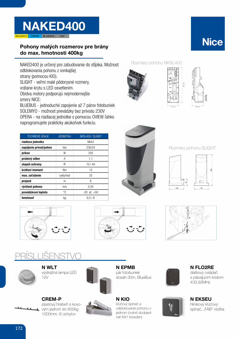
NAKED400
Pohony malých rozmerov pre bránydo max. hmotnosti 400kg
NAKED400 je určený pre zabudovanie do stĺpika. Možnost odblokovania pohonu z vonkajšejstrany (pomocou KIO). SLIGHT - veľmi malé pôdorysné rozmery,vrátane krytu s LED osvetlením.Obidva motory podporujú nejmodernejšiesmery NICE:BLUEBUS - jednoduché zapojenie až 7 párov fotobuniekSOLEMYO - možnost prevádzky bez prívodu 230VOPERA - na riadiacej jednotke s pomocou OVIEW ľahko naprogramujete prakticky akúkoľvek funkciu.
IV
14 15
IV
14 15
PRÍSLUŠENSTVO
VI
19
20
a
b
c
de
Rozmery pohonu NKSL400
TECHNICKÉ ÚDAJE JEDNOTKA NKSL400 / SLIGHT
riadiaca jednotka NKA3
napájenie prívod/pohon Vac 230/24
príkon W 250
prúdový odber A 1,1
stupeň ochrany IP 10 / 44
krútiaci moment Nm 12
max. zaťaženie cykly/hod 35
prejazd m 6
rýchlost pohonu m/s 0,34
prevádzková teplota °C -20 až +50
hmotnosť kg 6,5 / 8
N WLTvýstražná lampa LED 12V
CREM-Pplastový hrebeň s kovo-vým jadrom do 600kg1000mm, 6 úchytov
N EPMBpár fotobuniekdosah 30m, BlueBus
N KIOkľúčový spínač a odblokovanie pohonu v jednom (nutné doobjed-nať KA1 bowden)
N FLO2REdiaľkový ovládačs plávajúcim kódom 433,92MHz
I
405
mm
131 mm 135 mm
1
3 4 5
b
d c c h
l
bf
mg
inea
E C FD
C F AB
2
N EKSEUhliníkový kľúčový spínač, „FAB“ vložka
SOLEMYO OPERA BLUEBUS 24V
Rozmery pohonu SLIGHT
I
194
0 ÷
10
191 0 ÷ 50
194
0 ÷
10
1910 ÷ 50
20÷30
198 191
408
85
1
3 4 5
b
d c c g
i
bf
h lea
E C FD C F AB
2
173
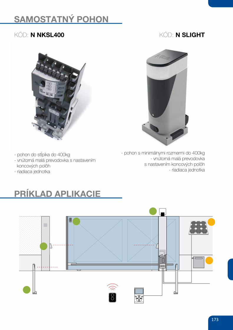
SAMOSTATNÝ POHON
KÓD: N NKSL400
- pohon do stĺpika do 400kg- vnútorná malá prevodovka s nastavením koncových polôh- riadiaca jednotka
PRÍKLAD APLIKACIE
KÓD: N SLIGHT
- pohon s minimálnymi rozmermi do 400kg- vnútorná malá prevodovka
s nastavením koncových polôh- riadiaca jednotka
174
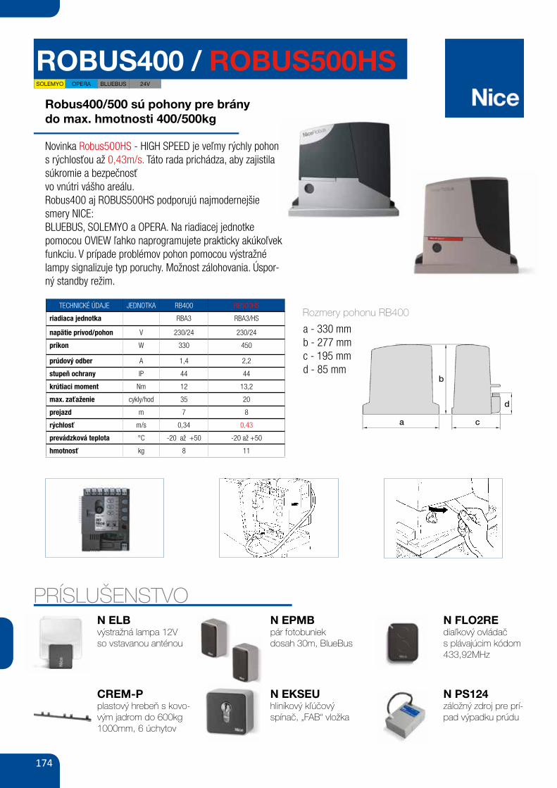
ROBUS400 / ROBUS500HSRobus400/500 sú pohony pre bránydo max. hmotnosti 400/500kg
Novinka Robus500HS - HIGH SPEED je veľmy rýchly pohon s rýchlosťou až 0,43m/s. Táto rada prichádza, aby zajistila súkromie a bezpečnosťvo vnútri vášho areálu.Robus400 aj ROBUS500HS podporujú najmodernejšie smery NICE:BLUEBUS, SOLEMYO a OPERA. Na riadiacej jednotke pomocou OVIEW ľahko naprogramujete prakticky akúkoľvek funkciu. V prípade problémov pohon pomocou výstražné lampy signalizuje typ poruchy. Možnost zálohovania. Úspor-ný standby režim.
TECHNICKÉ ÚDAJE JEDNOTKA RB400 RB500HS
riadiaca jednotka RBA3 RBA3/HS
napätie prívod/pohon V 230/24 230/24
príkon W 330 450
prúdový odber A 1,4 2,2
stupeň ochrany IP 44 44
krútiaci moment Nm 12 13,2
max. zaťaženie cykly/hod 35 20
prejazd m 7 8
rýchlosť m/s 0,34 0,43
prevádzková teplota °C -20 až +50 -20 až +50
hmotnosť kg 8 11
23
GB
7.8) AccessoriesThe following optional accessories are available for ROBUS:• PS124 PS124 24 V Buffer battery - 1,2Ah with integrated charger
battery.• SMXI or SMXIS 433.92MHz Radio receiver with digital Rolling code.
For information on the complete range of accessories, refer to theNice s.p.a. product catalogue.
30
Led 1 Description
• Function programming in progress.• If it flashes together with L4, it means that the user must carry out the leaf length recognition phase
(refer to Paragraph “4.4 Recognition length of the leaf”).
Led L6 Description
Led L5 Description
Led L3 Description
Led L2 Description
Led L4 Description
During normal operation the device indicates “Thrust” is not active.Off
Off
Tabella 23: LED’s on the control unit’s keys
During normal operation the device indicates “Automatic Closing” is not activeDuring normal operation the device indicates “Automatic Closing” is active.
• Function programming in progress.• If it flashes together with L2, it means that the user must carry out the device recognition phase (refer to
Paragraph “4.3 Recognition of the devices”).
on
It flashes
Off During normal operation the device indicates “Close after photo” is not active.During normal operation the device indicates “Close after photo” is active.
• Function programming in progress.• If it flashes together with L1, it means that the user must carry out the device recognition phase (refer to
Paragraph “4.3 Recognition of the devices”).
on
It flashes
Off During normal operation the device indicates “Always close” is not active.During normal operation the device indicates “Always close” is active.
During normal operation the device indicates “Stand-by” is not active.During normal operation the device indicates “Stand-by” is active.
• Function programming in progress.• If it flashes together with L3, it means that the user must carry out the leaf length recognition phase
(refer to Paragraph “4.4 Recognition length of the leaf”).
on
It flashes
Off on
It flashes
During normal operation the device indicates “Thrust” is active.Function programming in progress.
onIt flashes
During normal operation the device indicates “Pre-flashing” is not active.During normal operation the device indicates “Pre-flashing” is active.Function programming in progress.
Off onIt flashes
Led L7 Description During normal operation the device indicates that the CLOSE input activates a closing manoeuvre. During normal operation the device indicates that the CLOSE input activates a partial opening manoeuvre.Function programming in progress.
Off onIt flashes
Led L8 DescriptionDuring normal operation the device indicates that ROBUS is configured as Master. During normal operation the device indicates that ROBUS is configured as Slave. Function programming in progress.
Off onIt flashes
31
PRÍSLUŠENSTVON ELBvýstražná lampa 12Vso vstavanou anténou
CREM-Pplastový hrebeň s kovo-vým jadrom do 600kg1000mm, 6 úchytov
N EPMBpár fotobuniekdosah 30m, BlueBus
N EKSEUhliníkový kľúčovýspínač, „FAB“ vložka
N FLO2REdiaľkový ovládačs plávajúcim kódom 433,92MHz
N PS124záložný zdroj pre prí-pad výpadku prúdu
52
Sblocco e movimento manuale: prima di eseguire questa operazione porre attenzione che lo sblocco puòavvenire solo quando l’anta è ferma.
Per bloccare: eseguire, al contrario le stesse opera-zioni
Comando con sicurezze fuori uso: nel caso idispositivi di sicurezza presenti nel cancello nondovessero funzionare correttamente è possibilecomunque comandare il cancello.
• Azionare il comando del cancello (col telecomando,col selettore a chiave, ecc.); se tutto è a posto ilcancello si aprirà o chiuderà normalmente, altrimen-ti il lampeggiante farà alcuni lampeggi e la manovranon partirà (il numero di lampeggi dipende dal moti-vo per cui la manovra non può partire).
• In questo caso, entro tre secondi si deve azionarenuovamente e tenere azionato il comando.
• Dopo circa 2s inizierà il movimento del cancello inmodalità a “uomo presente”, cioè finché si mantieneil comando, il cancello continuerà a muoversi; appe-na il comando viene rilasciato, il cancello si ferma.
Con le sicurezze fuori uso è necessario farriparare quanto prima l’automatismo.
Sostituzione pila del telecomando: se il vostroradiocomando dopo qualche tempo vi sembra funzio-nare peggio, oppure non funzionare affatto, potrebbesemplicemente dipendere dall’esaurimento della pila (aseconda dell’uso, possono trascorrere da diversi mesifino ad oltre un anno). Ve ne potete accorgere dal fat-to che la spia di conferma della trasmissione non siaccende, è fioca, oppure si accende solo per un breveistante. Prima di rivolgervi all’installatore provate ascambiare la pila con quella di un altro trasmettitoreeventualmente funzionante: se questa fosse la causadell’anomalia, sarà sufficiente sostituire la pila con altradello stesso tipo.
Le pile contengono sostanze inquinanti: non gettarlenei rifiuti comuni ma utilizzare i metodi previsti dairegolamenti locali.
Siete soddisfatti? Nel caso voleste aggiungere nel-la vostra casa un nuovo impianto di automazione, rivol-gendovi allo stesso installatore e a Nice vi garantirete,oltre che la consulenza di uno specialista e i prodottipiù evoluti del mercato, il migliore funzionamento e lamassima compatibilità delle automazioni.Vi ringraziamo per aver letto queste raccomandazioni,e vi auguriamo la massima soddisfazione dal vostronuovo impianto: per ogni esigenza presente o futurarivolgetevi con fiducia al vostro installatore.
!
1 Far scorrere il dischetto copri serratura. 2 Inserire e ruotare la chiave in senso orario.
3 Tirare la maniglia di sblocco. 4 Muovere manualmente l’anta.
EN - Integration to manual Robus 600-1000
IT - Integrazione al manuale Robus 600-1000
FR - Addenda au guideRobus 600-1000
ES - Integración del manualRobus 600-1000
DE - Vervollständigung desHandbuchs Robus 600-1000
PL - Uzupełnienie do instrukcjiRobus 600-1000
NL - Aanvulling op de handleiding Robus 600-1000
RB400 - RUN1500For sliding gates
Cod
ice:
ISTR
B2A
.486
5 R
ev. 0
1 de
l 22
- 06
- 2
009
DICHIARAZIONE CE DI CONFORMITÀ / CE DECLARATION OF CONFORMITY
Nota - Il contenuto di questa dichiarazione corrisponde a quanto dichiarato nell’ultima revisione disponibile, prima della stampa di questo manuale, del documento ufficiale deposi-tato presso la sede di Nice Spa. Il presente testo è stato riadattato per motivi editoriali. / Note - The contents of this declaration correspond to those of the last revision availableof the official document, deposited at the registered offices of Nice S.p.a., before printing of this manual. The text herein has been re-edited for editorial purposes.
Numero / Number: 210/ROBUS Revisione / Revision: 2
Il sottoscritto Luigi Paro in qualità di Amministratore Delegato, dichiara sotto la propria responsabilità che il prodotto: / The undersigned Luigi Paro, managing director, declaresunder his sole responsibility that the following product:Nome produttore / Manufacturer’s name: NICE s.p.a.Indirizzo / Address: Via Pezza Alta 13, 31046 Z.I. Rustignè, Oderzo (TV) Italia / ItalyTipo / Type: Motoriduttore elettromeccanico con centrale incorporata / Ac electromechanical gearmotor with built-in control unitModello / Models: RB600, RB600P, RB1000, RB1000P, RB400KIT, RUN1500Accessori / Accessories: Ricevente radio SMXI, SMXIS; batteria di emergenza PS124 / Radio receiver SMXI, SMXIS; buffer battery PS124
Risulta conforme a quanto previsto dalla direttiva comunitaria: / Satisfies the essential requirements of the following Directives:
• 98/37/CE (89/392/CEE modificata) / 98/37/EC (89/392/EEC amended).Come previsto dalla direttiva 98/37/CE si avverte che non è consentita la messa in servizio del prodotto sopra indicato finché la macchina, in cui il prodotto è incorporato, non siastata identificata e dichiarata conforme alla direttiva 98/37/CE / As specified in the directive 98/37/CEE use of the product specified above is not admitted until the machine onwhich it is mounted has been identified and declared as conforming to the directive 98/37/CEE.Inoltre il prodotto risulta conforme a quanto previsto dalle seguenti direttive comunitarie, così come modificate dalla Direttiva 93/68/CEE del consiglio del 22 Luglio 1993: / Further-more, the product complies with the specifications of the following EC directives:• 2006/95/CEE(ex direttiva 73/23/CE) . / 2006/95/EEC (ex directive 73/23/EC).Secondo le seguenti norme armonizzate: / According to the following harmonised standards: EN 60335-1:1994+A11:1995+A1:1996+A13:1998+A14:1998+A15:2000+A2:2000+A16:2001• 2004/108/CEE(ex direttiva 89/336/CEE) / 2004/108/EEC (ex directive 89/336/EEC).Secondo la seguente norma armonizzata: / According to the following harmonised standards:EN 61000-6-2:2001; EN 61000-6-3:2007Inoltre risulta conforme, limitatamente per le parti applicabili, alle seguenti norme: / Furthermore, complies with the specifications, limitedly for the applicable the following standards:EN 60335-1:2002+A1:2004+A11:2004+A12:2006+ A2:2006, EN 60335-2-103:2003, EN 13241-1:2003; EN 12453:2002; EN 12445:2002; EN 12978:2003
Oderzo, 8 Maggio 2009 / Oderzo, 8 May 2009 Luigi Paro(Amministratore Delegato / Managing Director)
Il presente Addendum, riporta i dati specifici dei prodotti RB400 e RUN1500; le tabelle 2 e 3 contengono anche i dati riportati nelmanuale di riferimento del prodotto Robus 600-1000.
LIMITI D’IMPIEGO: generalmente RB400 è in grado di automatizzare cancelli con peso fino a 400 Kg oppure lunghezza fino a 7 m,mentre RUN1500 è in grado di automatizzare cancelli con peso fino a 1500 Kg oppure lunghezza fino a 14 m; vedere tabella 1 e 2.La lunghezza dell’anta permette di determinare il numero massimo di cicli per ora e di cicli consecutivi mentre il peso permette dideterminare la percentuale di riduzione dei cicli e la velocità massima consentita.
Tabella 2: limiti in relazione alla lunghezza dell’anta
ITALIANO
Lunghezza anta (m) cicli/ora massimi cicli consecutivi massimiRB400 RB600 RB1000 RUN1500 RB400 RB600 RB1000 RUN1500
Fino a 4 35 40 50 60 14 20 25 304 - 6 23 25 33 40 11 13 16 206 - 7 20 23 28 34 10 11 14 177 - 8 - 20 25 30 - 10 12 158 - 10 - - 20 24 - - 10 1210 - 12 - - 16 20 - - - 1012 - 14 - - - 17 - - - 8
CARATTERISTICHE TECNICHE SPECIFICHE
RB400 RB600-RB600P RB1000-RB1000P RUN1500
Pignone Z: 15; Pignone Z: 15; Modulo: 4; Pignone Z: 18, Modulo: 4; Passo: 12,6 mm; Modulo: 4;
Passo: 12,6 mm; Diametro primitivo: 60 mm Passo: 12.6 mm;Diametro Diametro
primitivo: 60 mm primitivo: 72 mm
12 Nm 18 Nm 27 Nm 35 Nm[400 N] [600 N] [900 N] [1000 N]
6 Nm 9 Nm 15 Nm 20 Nm[200 N] [300 N] [500 N] [560 N]
0,18 m/s 0,15 m/s 0,14 m/s 0,18 m/s
0,34 m/s 0,31 m/s 0,28 m/s 0,25 m/s
35 40 50 60
La centrale limita i cicli al massimo previsto nelle tabelle 2 e 3
10 minuti
Generalmente Robus e Run sono in grado di automatizzare cancelli con pesoe lunghezza secondo i limiti riportati nelle tabelle 2, 3 e 4
330 W 515 W [2,5 A] 450 W [2,3 A] 400 W[4,8 A versione/V1] [4,4 A versione/V1]
330 x 195 h 277 330 x 120 h 303 330 x 210 h 303 400 x 255 h 3908 Kg 11 Kg 13 Kg 19 Kg
Tabella 3: limiti in relazione al peso dell’anta
Peso dell’anta (kg) percentuale cicli velocità massima consentitaRB400 RB600 RB1000 RUN1500 RB400 RB600 RB1000 RUN1500
Fino a 200 100% 100% 100% 100% V6 V6 V6 V6200 - 400 50% 80% 90% 100% V5 V5 V5 V6400 - 500 - 60% 60% 95% - V4 V4 V6500 - 600 - 50% 100% 90% - V3 V4 V5600 - 700 - - 50% 85% - - V3 V5700 - 800 - - 47% 80% - - V3 V5800 - 900 - - 45% 75% - - V3 V5900 - 1000 - - 40% 70% - - V3 V41000 - 1200 - - - 60% - - - V41200 - 1350 - - - 65% - - - V31350 - 1500 - - - 60% - - - V3
MODELLO:
Pignone
Coppia massima allo spunto[corrispondente alla capacità di sviluppare unaforza per mettere in movimento l’anta]
Coppia nominale[corrispondente alla capacità di sviluppare unaforza per mettere in movimento l’anta]
Velocità alla coppia nominale
Velocità a vuoto(la centrale consente di programmare 6velocità pari a circa: 100, 85, 70, 55, 45, 30%)
Frequenza massima cicli/ora di funziona-mento[su un cancello standar da 4 m]
Tempo massimo di funzionamento continuo
Limiti d’impiego
Potenza massima assorbita allo spunto[corrispondenti ad Ampere]
Dimensioni (mm) e peso
Cet addenda contient des données spécifiques aux produits RB400 et RUN1500 ; les tableaux 2 et 3 contiennent aussi les donnéesfigurant dans le guide de référence du produit Robus 600-1000.
LIMITES D’APPLICATION : généralement RB400 est en mesure d’automatiser des portails pesant jusqu’à 400 kg ou mesurantjusqu’à 7 m de long, tandis que RUN1500 est en mesure d’automatiser des portails pesant jusqu’à 1500 kg ou mesurant jusqu’à 14m de long ; voir tableau 1 et 2. La longueur du vantail permet de déterminer le nombre maximum de cycles par heure et de cyclesconsécutifs tandis que le poids permet de déterminer le pourcentage de réduction des cycles et la vitesse maximum autorisée.
Tableau 2 : limites suivant la longueur du vantail
FRANÇAIS
Longueur vantail (m) cycles/heure maximums cycles consécutifs maximumsRB400 RB600 RB1000 RUN1500 RB400 RB600 RB1000 RUN1500
Jusqu’à 4 35 40 50 60 14 20 25 304 - 6 23 25 33 40 11 13 16 206 - 7 20 23 28 34 10 11 14 177 - 8 - 20 25 30 - 10 12 158 - 10 - - 20 24 - - 10 1210 - 12 - - 16 20 - - - 1012 - 14 - - - 17 - - - 8
CARACTÉRISTIQUES TECHNIQUES SPÉCIFIQUES
RB400 RB600-RB600P RB1000-RB1000P RUN1500
Pignon Z: 15; Pignon Z: 15; Module: 4; Pignon Z: 18, Module: 4; Pas: 12,6 mm; Module: 4;
Pas: 12,6 mm; Diamètre primitif: 60 mm Pas: 12.6 mm; Diamètre Diamètre
primitif: 60 mm primitif: 72 mm
12 Nm 18 Nm 27 Nm 35 Nm[400 N] [600 N] [900 N] [1000 N]
6 Nm 9 Nm 15 Nm 20 Nm[200 N] [300 N] [500 N] [560 N]
0,18 m/s 0,15 m/s 0,14 m/s 0,18 m/s
0,34 m/s 0,31 m/s 0,28 m/s 0,25 m/s
35 40 50 60
La logique de commande limite les cycles au maximum prévu dans les tableaux 2 et 3
10 minutes
Généralement Robus et Run sontt en mesure d’automatiser des portails d’un poids ou d’une longueur respectant les limites prévues dans les tableaux 2, 3 et 4
330 W 515 W [2,5 A] 450 W [2,3 A] 400 W[4,8 A version/V1] [4,4 A version/V1]
330 x 195 h 277 330 x 120 h 303 330 x 210 h 303 400 x 255 h 3908 Kg 11 Kg 13 Kg 19 Kg
Tableau 3 : limites suivant le poids du vantail
Poids du vantail (kg) pourcentage cycles vitesse maximum admissibleRB400 RB600 RB1000 RUN1500 RB400 RB600 RB1000 RUN1500
Jusqu’à 200 100% 100% 100% 100% V6 V6 V6 V6200 - 400 50% 80% 90% 100% V5 V5 V5 V6400 - 500 - 60% 60% 95% - V4 V4 V6500 - 600 - 50% 100% 90% - V3 V4 V5600 - 700 - - 50% 85% - - V3 V5700 - 800 - - 47% 80% - - V3 V5800 - 900 - - 45% 75% - - V3 V5900 - 1000 - - 40% 70% - - V3 V41000 - 1200 - - - 60% - - - V41200 - 1350 - - - 65% - - - V31350 - 1500 - - - 60% - - - V3
MODÈLE :
Pignon
Couple maximum au démarrage[correspondant à la capacité de développerune force pour mettre en mouvement le vantail]
Couple nominal [correspondant à la capacité de développerune force pour mettre en mouvement le vantail]
Vitesse au couple nominal
Vitesse à vide (a logique de commande per-met de programmer 6 vitesses, égales à envi-ron : 100, 85, 70, 55, 45, 30%)
Fréquence maximum cycles/heure de fonctionnement[sur un portail standard de 4 m]
Temps maximum de fonctionnement continu
Limites d’utilisation
Puissance maximum absorbée au démar-rage [correspondant à ampères]
Dimensions et poids
This Addendum provides the specific data of products RB400 and RUN1500; tables 2 and 3 also contain data specified in the referencemanual of the product Robus 600-1000.
APPLICATION LIMITS: in general, RB400 is designed for the automation of gates with weights up to 400 Kg and lengths up to 7 m,while RUN1500 is designed for the automation of gates with weights up to 1500 Kg and lengths up to 14 m; see table 1 and 2.The length of the leaf enables the calculation of the maximum number of cycles per hour and the maximum number of consecutive cycles,while the weight enables calculation of the percentage of reduction in the number of cycles at the maximum admissible speed.
Table 2: limits in relation to the leaf length
ENGLISH
Leaf length (m) maximum cycles/hour maximum consecutive cyclesRB400 RB600 RB1000 RUN1500 RB400 RB600 RB1000 RUN1500
Up to 4 35 40 50 60 14 20 25 304 - 6 23 25 33 40 11 13 16 206 - 7 20 23 28 34 10 11 14 177 - 8 - 20 25 30 - 10 12 158 - 10 - - 20 24 - - 10 1210 - 12 - - 16 20 - - - 1012 - 14 - - - 17 - - - 8
TECHNICAL SPECIFICATIONS
RB400 RB600-RB600P RB1000-RB1000P RUN1500
Pinion Z: 15; Pinion Z: 15; Module: 4; Pinion Z: 18, Module: 4; Pitch: 12,6 mm; Module: 4;
Pitch: 12,6 mm; Primitive diameter: 60 mm Pitch: 12.6 mm; Primitive Primitive
diameter: 60 mm diameter: 72 mm
12 Nm 18 Nm 27 Nm 35 Nm[400 N] [600 N] [900 N] [1000 N]
6 Nm 9 Nm 15 Nm 20 Nm[200 N] [300 N] [500 N] [560 N]
0,18 m/s 0,15 m/s 0,14 m/s 0,18 m/s
0,34 m/s 0,31 m/s 0,28 m/s 0,25 m/s
35 40 50 60
The control unit limits the number of cycles tothe maximum value as stated in tables 2 and 3
10 minutes
In general Robus and Run are designed for the automation of gates withweights and lengths within the limits specified in tables 2, 3 and 4
330 W 515 W [2,5 A] 450 W [2,3 A] 400 W[4,8 A version/V1] [4,4 A version/V1]
330 x 195 h 277 330 x 120 h 303 330 x 210 h 303 400 x 255 h 3908 Kg 11 Kg 13 Kg 19 Kg
Table 3: limits in relation to the leaf weight
Leaf weight (kg) percentage of cycles maximum admissible speedRB400 RB600 RB1000 RUN1500 RB400 RB600 RB1000 RUN1500
Up to 200 100% 100% 100% 100% V6 V6 V6 V6200 - 400 50% 80% 90% 100% V5 V5 V5 V6400 - 500 - 60% 60% 95% - V4 V4 V6500 - 600 - 50% 100% 90% - V3 V4 V5600 - 700 - - 50% 85% - - V3 V5700 - 800 - - 47% 80% - - V3 V5800 - 900 - - 45% 75% - - V3 V5900 - 1000 - - 40% 70% - - V3 V41000 - 1200 - - - 60% - - - V41200 - 1350 - - - 65% - - - V31350 - 1500 - - - 60% - - - V3
MODEL:
Pinion
Maximum start-up torque[corresponding to the capacity to generate aset force to move the gate leaf]
Nominal torque [corresponding to the capacity to generate aset force to move the gate leaf]
Speed at nominal torque
Speed under no load(the control unit enables programming of sixspeeds at approx.: 100, 85, 70, 55, 45, 30%)
Maximum frequency of cycles per hour ofoperation[on a standard gate of 4 m]
Maximum continuous operation time
Application limits
Maximum power absorption on start-up[corresponding to Amps]
Dimensions (mm) and weight
RUN1500RB400 RUN1500
a 330 mm 400 mmb 277 mm 390 mmc 195 mm 255 mmd 85 mm 108 mm
a c
b
d
400 0÷50
0÷10
240
4000÷50
0÷10
240
max
. 40
mm
Rozmery pohonu RB400
a - 330 mmb - 277 mmc - 195 mmd - 85 mm
SOLEMYO OPERA BLUEBUS 24V
175
SADY POHONOV (do 400kg)
KÓD SADY: N ROBUSKIT400-Z
Sada obsahuje: pohon so vstavanou riadiacou jednotkou, diaľkový ovládač, prijímač a pár fotobuniek
Kód: N ON2E Kód: N EPMBKód: N OXI
PRÍKLAD APLIKACIE
KÓD SADY: N ROBUSKIT400-K
Sada obsahuje: pohon so vstavanou riadiacou jednotkou, diaľkový ovládač, prijímač, pár fotobunieka výstražnou lampu
Kód: N ON2E Kód: N EPMB Kód: N ELBKód: N OXI
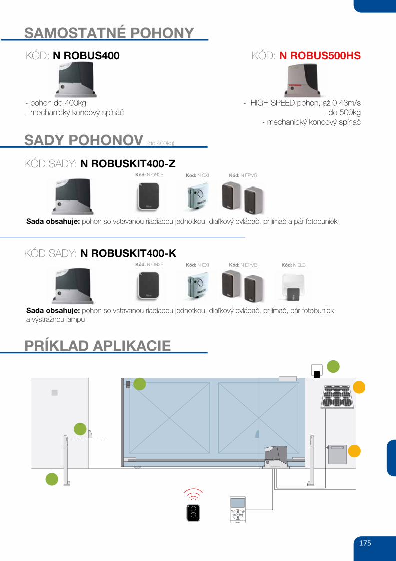
SAMOSTATNÉ POHONY
- pohon do 400kg- mechanický koncový spínač
- HIGH SPEED pohon, až 0,43m/s- do 500kg
- mechanický koncový spínač
KÓD: N ROBUS400 KÓD: N ROBUS500HS
176
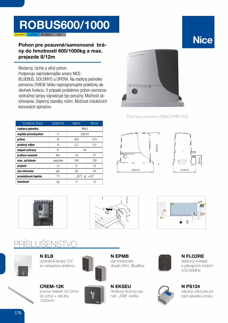
ROBUS600/1000
Pohon pre posuvné/samonosné brá-ny do hmotnosti 600/1000kg a max. prejezde 8/12m
Moderný, rýchly a silný pohon.Podporuje najmodernejšie smery NICE:BLUEBUS, SOLEMYO a OPERA. Na riadicej jednotke pomocou OVIEW ľahko naprogramujete prakticky ak-úkoľvek funkciu. V prípade problémov pohon pomocou výstražnej lampy signalizuje typ poruchy. Možnost zá-lohovania. Úsporný standby režim. Možnost indukčních koncových spínačov.
TECHNICKÉ ÚDAJE JEDNOTKA RB600 RB100
riadiaca jednotka RBA3
napätie prívod/pohon V 230/24
príkon W 450 515
prúdový odber A 2,3 2,5
stupeň ochrany IP 44
krútiaci moment Nm 18 27
max. zaťaženie cykly/den 100 150
prejazd m 8 12
čas otvorenia sec. 26 45
prevádzková teplota °C -20°C až +50°
hmotnosť kg 11 13
PRÍSLUŠENSTVON ELBvýstražná lampa 12Vso vstavanou anténou
CREM-12Kkovový hrebeň 3012mm3x úchyt + skrutky1000mm
N EPMBpár fotobuniekdosah 30m, BlueBus
N EKSEUhliníkový kľúčový spí-nač, „FAB“ vložka
N FLO2REdiaľkový ovládačs plávajúcim kódom 433,92MHz
N PS124záložný zdroj pre prí-pad výpadku prúdu
30
ROBUS è una linea di motoriduttori elettromeccanici irreversibili,destinati all'automazione di cancelli scorrevoli. Dispongono di unacentrale elettronica di controllo e di un connettore per il ricevitore delradiocomando SMXI o SMXIS (opzionali). I collegamenti elettrici ver-so i dispositivi esterni sono semplificati grazie all'uso di “BlueBUS”,una tecnica che permette di collegare più dispositivi con soli 2 fili.
ROBUS funzionano mediante energia elettrica, in caso di mancanzadi alimentazione dalla rete elettrica, è possibile effettuare lo sbloccomediante apposita chiave e muovere manualmente il cancello;oppure è possibile usare l'accessorio opzionale: batteria tamponePS124 che permette alcune manovre anche in assenza di alimenta-zione da rete.
Della linea ROBUS fanno parte i prodotti le cui differenze principali sono descritte in tabella 1.
Nota: 1Kg = 9,81N quindi, ad esempio: 600N = 61Kg
2) Descrizione prodotto e destinazione d’uso
1
Motoriduttore tipo RB600 RB600P RB1000 RB1000PTipo di finecorsa elettromeccanico di prossimità induttivo elettromeccanico di prossimità induttivoLunghezza massima anta 8m 12mPeso massimo anta 600Kg 1000KgCoppia massima allo spunto 18Nm 27Nm(corrispondenti a forza) (600N) (900N)Motore e trasformatore Motore 24Vcc Ø 77mm Motore 24Vcc Ø 115mm
Trasformatore a colonna EI Trasformatore toroidale
Tabella 1: comparazione caratteristiche essenziali motoriduttore ROBUS
2.1) Limiti d’impiegoI dati relativi alle prestazioni dei prodotti della linea ROBUS sonoriportati nel capitolo “8 Caratteristiche tecniche” e sono gli unici valo-ri che consentono la corretta valutazione dell'idoneità all'uso.Le caratteristiche strutturali di ROBUS li rendono adatti all'uso suante scorrevoli, secondo i limiti riportati nelle tabelle 2, 3 e 4.
La reale idoneità di ROBUS ad automatizzare un determinato can-cello scorrevole dipende dagli attriti e da altri fenomeni, anche occa-sionali, come la presenza di ghiaccio che potrebbe ostacolare ilmovimento dell'anta.Per una verifica reale è assolutamente indispensabile misurare la for-za necessaria per muovere l'anta in tutta la sua corsa e controllareche questa non superi la metà della “coppia nominale” riportata nelcapitolo “8 Caratteristiche tecniche” (è consigliato un margine del50% perché le condizioni climatiche avverse possono far aumentaregli attriti); inoltre per stabilire il numero di cicli/ora; i cicli consecutivi e
la velocità massima consentita occorre considerare quanto riportatonelle tabelle 2 e 3.
RB600, RB600P RB1000, RB1000PLunghezza anta (m) cicli/ora massimi cicli consecutivi massimi cicli/ora massimi cicli consecutivi massimiFino a 4 40 20 50 254 ÷ 6 25 13 33 166 ÷ 8 20 10 25 128 ÷ 10 --- --- 20 1010 ÷ 12 --- --- 16 8
Tabella 2: limiti in relazione alla lunghezza dell'anta
330mm 210mm
303m
m
92m
m
Rozmery pohonov RB600/RB1000
52
Sblocco e movimento manuale: prima di eseguire questa operazione porre attenzione che lo sblocco puòavvenire solo quando l’anta è ferma.
Per bloccare: eseguire, al contrario le stesse opera-zioni
Comando con sicurezze fuori uso: nel caso idispositivi di sicurezza presenti nel cancello nondovessero funzionare correttamente è possibilecomunque comandare il cancello.
• Azionare il comando del cancello (col telecomando,col selettore a chiave, ecc.); se tutto è a posto ilcancello si aprirà o chiuderà normalmente, altrimen-ti il lampeggiante farà alcuni lampeggi e la manovranon partirà (il numero di lampeggi dipende dal moti-vo per cui la manovra non può partire).
• In questo caso, entro tre secondi si deve azionarenuovamente e tenere azionato il comando.
• Dopo circa 2s inizierà il movimento del cancello inmodalità a “uomo presente”, cioè finché si mantieneil comando, il cancello continuerà a muoversi; appe-na il comando viene rilasciato, il cancello si ferma.
Con le sicurezze fuori uso è necessario farriparare quanto prima l’automatismo.
Sostituzione pila del telecomando: se il vostroradiocomando dopo qualche tempo vi sembra funzio-nare peggio, oppure non funzionare affatto, potrebbesemplicemente dipendere dall’esaurimento della pila (aseconda dell’uso, possono trascorrere da diversi mesifino ad oltre un anno). Ve ne potete accorgere dal fat-to che la spia di conferma della trasmissione non siaccende, è fioca, oppure si accende solo per un breveistante. Prima di rivolgervi all’installatore provate ascambiare la pila con quella di un altro trasmettitoreeventualmente funzionante: se questa fosse la causadell’anomalia, sarà sufficiente sostituire la pila con altradello stesso tipo.
Le pile contengono sostanze inquinanti: non gettarlenei rifiuti comuni ma utilizzare i metodi previsti dairegolamenti locali.
Siete soddisfatti? Nel caso voleste aggiungere nel-la vostra casa un nuovo impianto di automazione, rivol-gendovi allo stesso installatore e a Nice vi garantirete,oltre che la consulenza di uno specialista e i prodottipiù evoluti del mercato, il migliore funzionamento e lamassima compatibilità delle automazioni.Vi ringraziamo per aver letto queste raccomandazioni,e vi auguriamo la massima soddisfazione dal vostronuovo impianto: per ogni esigenza presente o futurarivolgetevi con fiducia al vostro installatore.
!
1 Far scorrere il dischetto copri serratura. 2 Inserire e ruotare la chiave in senso orario.
3 Tirare la maniglia di sblocco. 4 Muovere manualmente l’anta.
SOLEMYO OPERA BLUEBUS 24V
177
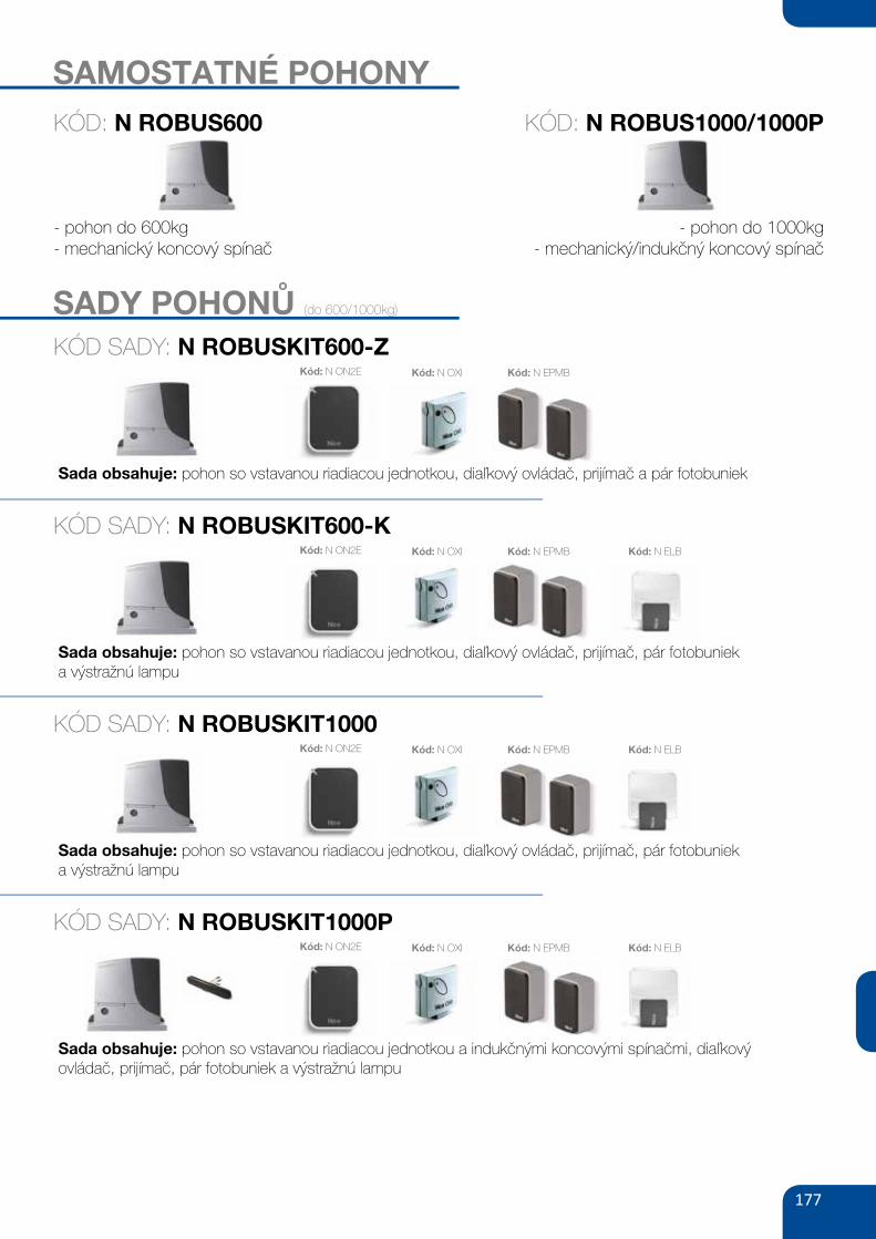
SAMOSTATNÉ POHONY
- pohon do 600kg- mechanický koncový spínač
- pohon do 1000kg- mechanický/indukčný koncový spínač
SADY POHONŮ (do 600/1000kg)
KÓD: N ROBUS600 KÓD: N ROBUS1000/1000P
KÓD SADY: N ROBUSKIT600-Z
Sada obsahuje: pohon so vstavanou riadiacou jednotkou, diaľkový ovládač, prijímač a pár fotobuniek
Kód: N ON2E Kód: N EPMBKód: N OXI
KÓD SADY: N ROBUSKIT600-K
Sada obsahuje: pohon so vstavanou riadiacou jednotkou, diaľkový ovládač, prijímač, pár fotobunieka výstražnú lampu
Kód: N ON2E Kód: N EPMBKód: N OXI Kód: N ELB
KÓD SADY: N ROBUSKIT1000
Sada obsahuje: pohon so vstavanou riadiacou jednotkou, diaľkový ovládač, prijímač, pár fotobunieka výstražnú lampu
Kód: N ON2E Kód: N EPMBKód: N OXI Kód: N ELB
KÓD SADY: N ROBUSKIT1000P
Sada obsahuje: pohon so vstavanou riadiacou jednotkou a indukčnými koncovými spínačmi, diaľkový ovládač, prijímač, pár fotobuniek a výstražnú lampu
Kód: N ON2E Kód: N EPMBKód: N OXI Kód: N ELB
178
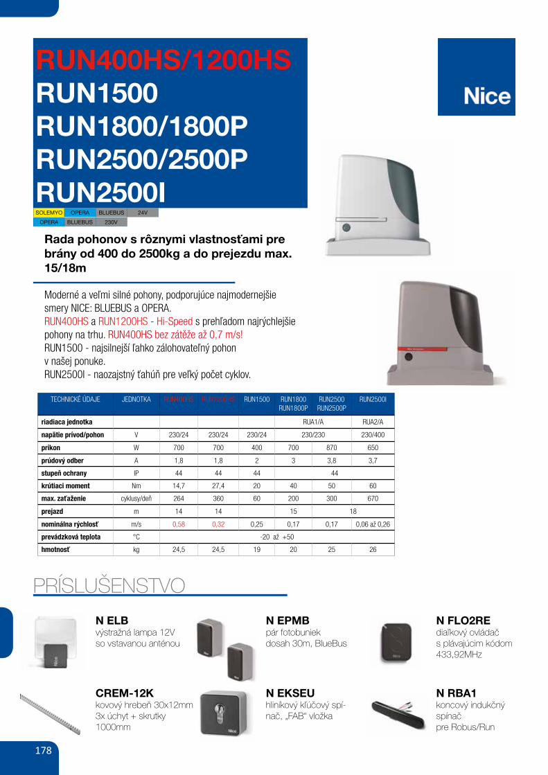
RUN400HS/1200HSRUN1500RUN1800/1800PRUN2500/2500PRUN2500I
Rada pohonov s rôznymi vlastnosťami pre brány od 400 do 2500kg a do prejezdu max. 15/18m
Moderné a veľmi silné pohony, podporujúce najmodernejšie smery NICE: BLUEBUS a OPERA.RUN400HS a RUN1200HS - Hi-Speed s prehľadom najrýchlejšie pohony na trhu. RUN400HS bez zátěže až 0,7 m/s!RUN1500 - najsilnejší ľahko zálohovateľný pohonv našej ponuke.RUN2500I - naozajstný ťahúň pre veľký počet cyklov.
TECHNICKÉ ÚDAJE JEDNOTKA RUN400HS RUN1200HS RUN1500 RUN1800RUN1800P
RUN2500RUN2500P
RUN2500I
riadiaca jednotka RUA1/A RUA2/A
napätie prívod/pohon V 230/24 230/24 230/24 230/230 230/400
príkon W 700 700 400 700 870 650
prúdový odber A 1,8 1,8 2 3 3,8 3,7
stupeň ochrany IP 44 44 44 44
krútiaci moment Nm 14,7 27,4 20 40 50 60
max. zaťaženie cyklusy/deň 264 360 60 200 300 670
prejazd m 14 14 15 18
nominálna rýchlosť m/s 0,58 0,32 0,25 0,17 0,17 0,06 až 0,26
prevádzková teplota °C -20 až +50
hmotnosť kg 24,5 24,5 19 20 25 26
PRÍSLUŠENSTVO
N ELBvýstražná lampa 12Vso vstavanou anténou
CREM-12Kkovový hrebeň 30x12mm3x úchyt + skrutky1000mm
N EPMBpár fotobuniekdosah 30m, BlueBus
N EKSEUhliníkový kľúčový spí-nač, „FAB“ vložka
N FLO2REdiaľkový ovládačs plávajúcim kódom 433,92MHz
N RBA1koncový indukčný spínačpre Robus/Run
OPERA BLUEBUS 230V
SOLEMYO OPERA BLUEBUS 24V
179
4
RUN is a range of irreversible electromechanical gearmotors used forthe automation of sliding gates. They are equipped with an electron-ic control unit and an “SM” type connector for radio control receivers(optional ). Electrical connections to external devices are facilitatedthanks to the use of the “BlueBUS” system, which enables the con-nection of several devices by means of just 2 wires. The list ofdevices compatible for connection to the Run BlueBUS is given inchapter 7.3.1 "BlueBUS"; an updated list, with relative compatibility
is also available at: www.niceforyou.com. RUN is equipped with aconnector for remote programming units to enable complete andquick management of installation, maintenance, troubleshooting ofany malfunctions; refer also to 7.8.1 "Remote programming unit".RUN is electrically powered, in the event of a power failure, thedevice can be released by means of the special key, to enable man-ual movement of the gate.
Other products are also part of the RUN range, the difference of which is described in table 1.
Note: 1Kg = 9,81N for example: 1390N = 142 Kg
2) Product description and applications
1
Gearmotor type RUN1800 RUN1800P RUN2500 RUN2500PLimit switch type electromechanical inductive proximity electromechanical inductive proximityMaximum leaf length 15m 18mMaximum leaf weight 1800Kg 2500KgPeak thrust 40Nm 50Nm(corresponding to a force) (1110N) (1390N))Motor Single phase asynchronous maximum 700W Single phase asynchronous maximum 870W
Table 1: comparison of the RUN gearmotor main characteristics
2.1) Operating limitsChapter 8 “Technical Characteristics” provides the only data neededto determine whether the products of the RUN line are suitable forthe intended application. The structural characteristics of RUN makeit suitable for use on sliding leaves in conformity with the limits spec-ified in tables 2, 3 and 4.
The effective suitability of RUN to automate a sliding gate dependson friction and other factors, even occasional, such as the presenceof ice which could obstruct leaf movement. To ensure suitability, it isabsolutely vital to measure the force necessary to move the leafthroughout its entire run and ensure that this is less than half of the“nominal torque” indicated in chapter 8 “Technical characteristics” (a50% margin on the force is recommended, as unfavourable climaticconditions may cause an increase in the friction); furthermore, the
data specified in tables 2 and 3 should be taken into account toestablish the number of cycles/hour and consecutive cycles.
RUN1800/ RUN1800P RUN2500/ RUN2500PLeaf width(m) max. cycles/hour max. consecutive cycles max. cycles/hour max. consecutive cyclesUp to 6 42 28 42 426 ÷ 9 28 18 28 289 ÷ 12 21 14 21 2112 ÷ 15 17 11 17 1715 ÷ 18 14 14
Table 2: limits in relation to the length of the leaf
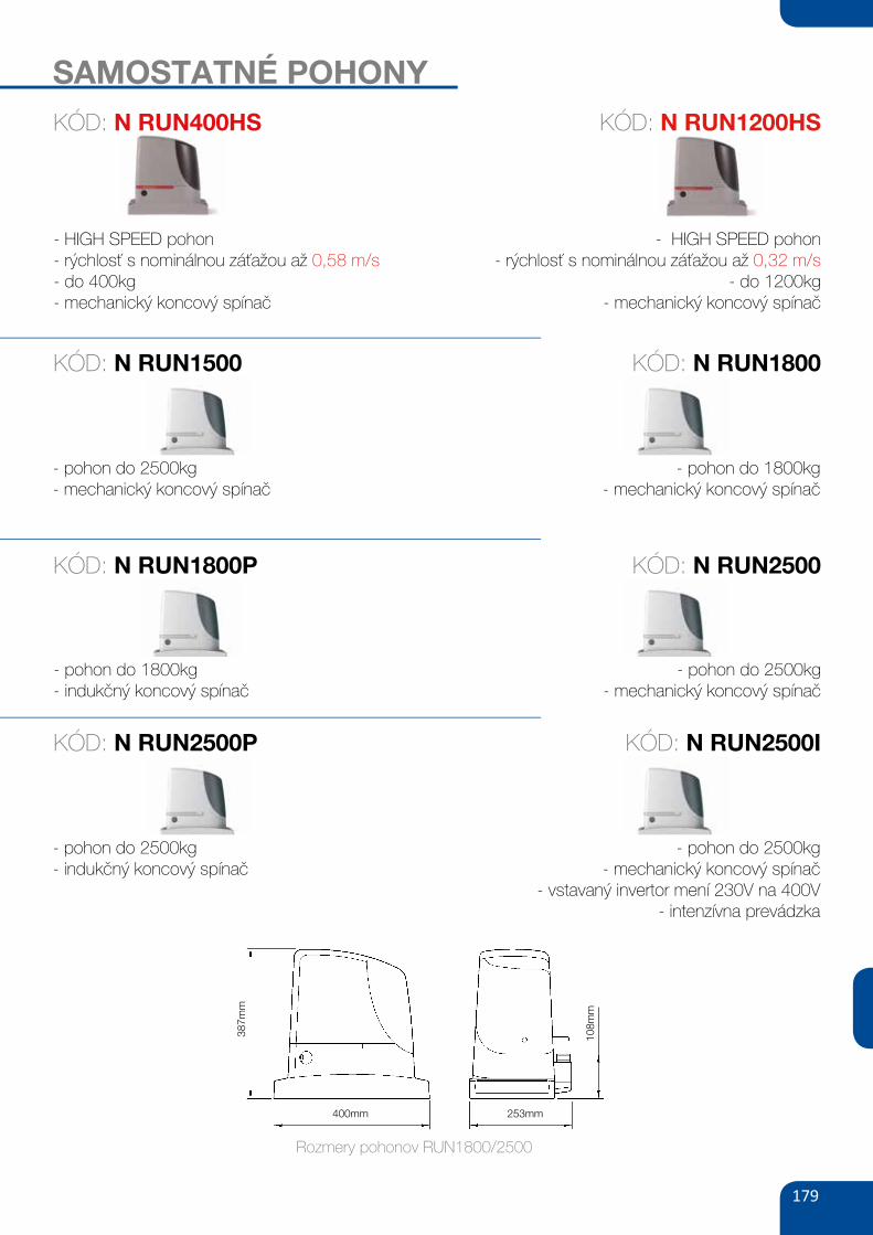
400mm 253mm
387m
m
108m
m
Rozmery pohonov RUN1800/2500
SAMOSTATNÉ POHONY
- HIGH SPEED pohon- rýchlosť s nominálnou záťažou až 0,58 m/s- do 400kg- mechanický koncový spínač
- HIGH SPEED pohon- rýchlosť s nominálnou záťažou až 0,32 m/s
- do 1200kg- mechanický koncový spínač
KÓD: N RUN400HS KÓD: N RUN1200HS
- pohon do 2500kg- mechanický koncový spínač
- pohon do 1800kg- mechanický koncový spínač
KÓD: N RUN1500 KÓD: N RUN1800
- pohon do 1800kg- indukčný koncový spínač
- pohon do 2500kg- mechanický koncový spínač
KÓD: N RUN1800P KÓD: N RUN2500
- pohon do 2500kg- indukčný koncový spínač
- pohon do 2500kg- mechanický koncový spínač
- vstavaný invertor mení 230V na 400V- intenzívna prevádzka
KÓD: N RUN2500P KÓD: N RUN2500I
180
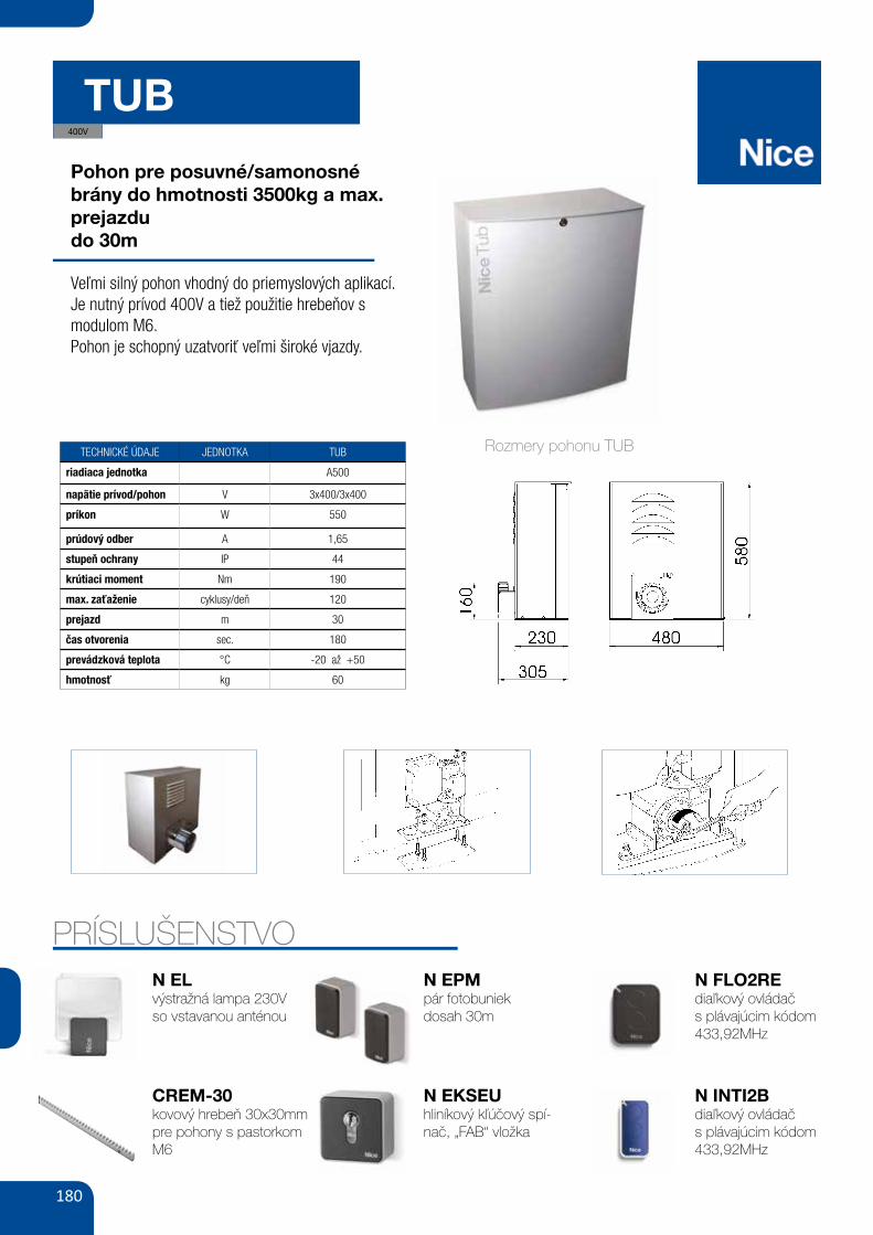
TUB
Pohon pre posuvné/samonosné brány do hmotnosti 3500kg a max. prejazdudo 30m
Veľmi silný pohon vhodný do priemyslových aplikací.Je nutný prívod 400V a tiež použitie hrebeňov s modulom M6.Pohon je schopný uzatvoriť veľmi široké vjazdy.
TECHNICKÉ ÚDAJE JEDNOTKA TUB
riadiaca jednotka A500
napätie prívod/pohon V 3x400/3x400
príkon W 550
prúdový odber A 1,65
stupeň ochrany IP 44
krútiaci moment Nm 190
max. zaťaženie cyklusy/deň 120
prejazd m 30
čas otvorenia sec. 180
prevádzková teplota °C -20 až +50
hmotnosť kg 60
GB
5
3.2) Installation of the gear motor If a base for the gear motor already exists, fixing must be performeddirectly to the surface by means of expansion bolts.If this is not so, it is necessary to: 1. Dig an adequately large foundation hole.2. Prepare one or more conduits for the electrical cables as shown
in Figure 53. Assemble the four clamps on the foundation plate setting one nut
underneath and one on top of the plate as in fig. 3. so that thethreaded section protrudes out of the plate as much as possible.
4. Pour the concrete and, before it starts to harden, set the founda-tion plate checking that it is parallel to the leaf and perfectly levelas shown in Fig. 5. Wait for the concrete to harden completely
5. Remove the body from the gear motor following the procedureshown in Fig.7 in reverse order.
6. Place the gear motor on top of the foundation plate and make sureit is perfectly parallel to the leaf, then secure it by tightening the 4nuts with washers to the respective clamps as shown in Fig. 6.
7. Release the pinion as shown in the “Release and manual move-ment” paragraph in the Chapter “Instructions and Warnings forusers of the TUB3500 gear motor”
8. Open the leaf up completely and place the first piece of the rackon the pinion and check that the beginning of the rack corre-sponds to the beginning of the leaf. Make sure that there is atleast 2÷3 mm of play between the rack and the pinion, then fas-ten the rack to the leaf using suitable means.
In order to prevent the weight of the leaf from affecting thegear motor, it is important that there is a play of 2÷3 mmbetween the rack and the pinion.
9. Slide the leaf, using the pinion as a reference point for the fas-tening the other elements of the rack
10. Cut away any excess of the rack11. Open and close the gate several times and make sure that the
rack is aligned with the pinion with a maximum tolerance of 10-15 mm. Moreover, check that the play of 2-3 mm between thepinion and the rack has been respected along the entire length.
12. Fix the two “Opening” and “Closing” limit switch brackets withthe relative dowels to the outer sides of the rack as shown in Fig-ure 4. Considering that the leaf will slide for a further 2÷3 cmafter the limit switches have activated, the brackets should bepositioned at a sufficient distance from the mechanical stops.
13. Perform the operation described in point 7 in reverse and blockthe pinion.
14. Secure the body to the TUB3500 as shown in Fig. 7 and ensurethat the limit switch lever positioned above the pinion movesfreely.
15. Close the gear motor door and make sure that the safetymicroswitch positioned to the right of the electric motor is acti-vated.
!
3
6 7
4 5
PRÍSLUŠENSTVON ELvýstražná lampa 230Vso vstavanou anténou
CREM-30kovový hrebeň 30x30mmpre pohony s pastorkom M6
N EPMpár fotobuniekdosah 30m
N FLO2REdiaľkový ovládačs plávajúcim kódom 433,92MHz
70
9 10
11 12
Ontgrendeling en manoeuvre met de hand: voordat u deze handeling gaat uitvoeren dient u er aan te denkendat ontgrendeling alleen kan plaats vinden wanneer de vleugel stil staat.1. Open de deur van TUB3500 met de meegeleverde sleutel van afbeelding 9.2. Pak de inbussleutel en steek die in de as van afbeelding 10.3. Draai de schroef die in de as zit helemaal vast, zoals op afbeelding 11 aangegeven is.4. Verwijder de inbussleutel en sluit de deur van TUB3500 weer.5. Beweeg de vleugel met de hand zoals op afbeelding 12 aangegeven is.
Voor vergrendeling: voer dezelfde handelingen in omgekeerde volgorde uit
In geval van storing dient u de automatisering zo snel mogelijk te laten repareren.
Bent u tevreden? Indien u in uw huis nog een nieuwe automatiseringsinstallatie zou willen, kunt u zich, wanneer uzich tot dezelfde installateur en Nice wendt, van de adviezen van een specialist en de meest geavanceerde productenop de markt verzekeren. Het resultaat: een automatisering die het best functioneert en een maximale compatibiliteit metde andere automatiseringen heeft.Wij bedanken u voor het lezen van deze aanbevelingen, en wij hopen dat u veel plezier van uw nieuwe installatie zulthebben: wend u voor elke vraag, nu of in de toekomst, vol vertrouwen tot uw installateur.
GB
3
The TUB3500 is a sliding gate gear motor of significant dimensionfor industrial use, with built-in control unit and is also prearranged forthe inclusion of NICE receivers. The gear motor, which functions electrically, can be disengaged bymeans of a key, thereby allowing the gate to be opened manually.
• Do not modify any components unless such action is specified in thismanual.Operations of this type are likely to lead to malfunctions. NICE dis-claims any liability for damage resulting from modified products.
• During installation and use, ensure that solid objects or liquids do notpenetrate inside the control unit or other open devices. If necessary,please contact the NICE customer service department; the use ofTUB3500 in these conditions can be dangerous.
• The automation system must not be used until it has been commis-sioned as described in chapter 5: “ Testing and commissioning”.
• The packing materials of TUB3500 must be disposed of in compliancewith local regulations.
• If a fault occurs that cannot be solved using the information providedin this manual, refer to the NICE customer service department.
• In the event that any automatic switches are tripped or fuses blown,you must identify the fault and eliminate it before resetting the switch-es or replacing fuses.
• Before accessing the terminals within the TUB3500, disconnect allpower supply circuits, by means of the magneto- thermal switch forexample on the control unit.
2) Product description and intended use
2.1) Operating limits The data relating to the performance of the TUB3500 are indicatedin chapter 7 “Technical characteristics” and are the only values thatallow the use capabilities to be correctly evaluated. In general, TUB3500 is suitable for the automation of gates up to3500 Kg or up to 30 m in length following that indicated in table 1.
1
Length of leaf in metres Maximum cycles/hour Up to 5 305÷10 1510÷15 1015÷20 720÷25 625÷30 5
Table 1: limits in relation to the length of the leaf
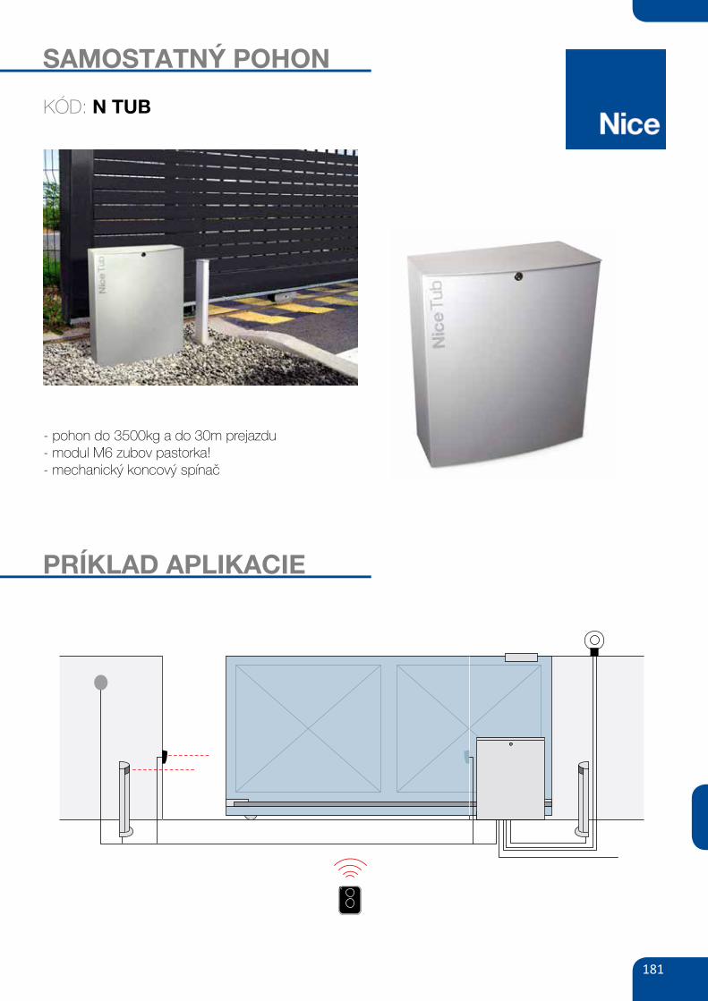
2.2) Typical systemThe figure below indicates a typical sliding gate automation system using the TUB3500.
2
1. Key operated selector switch2. Photocell on post3. FOTO photocells4. Main fixed edge (optional)5. Main moveable edge
6. “Open” stop bracket7. Rack8. Secondary fixed edge (optional)9. Flashing light10. Aerial
11. Motor12. “Closed” stop bracket 13. Secondary moveable edge (optional)14. Radio transmitter
Rozmery pohonu TUB
N EKSEUhliníkový kľúčový spí-nač, „FAB“ vložka
400V
N INTI2Bdiaľkový ovládačs plávajúcim kódom 433,92MHz
181
SAMOSTATNÝ POHON
- pohon do 3500kg a do 30m prejazdu- modul M6 zubov pastorka! - mechanický koncový spínač
PRÍKLAD APLIKACIE
KÓD: N TUB
183
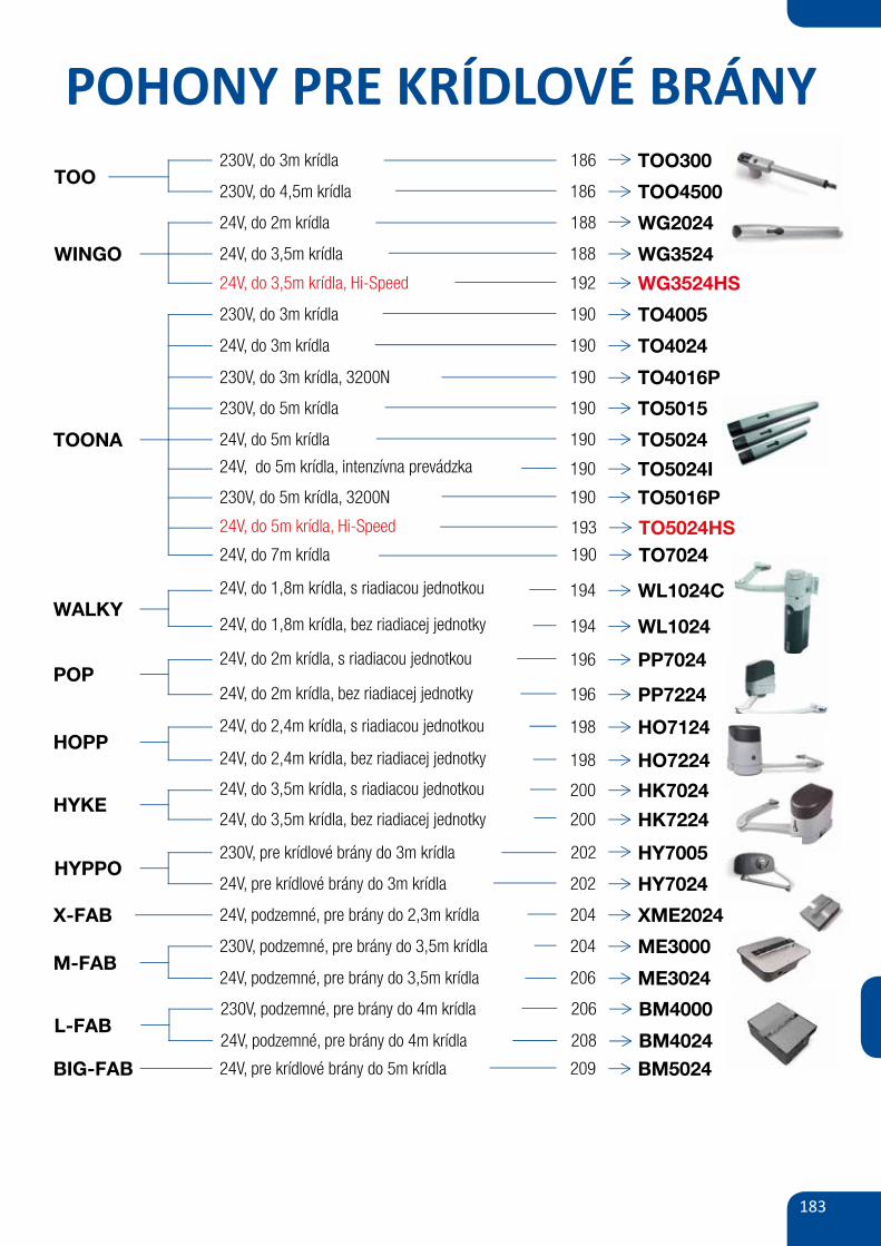
POHONY PRE KRÍDLOVÉ BRÁNYTOO
230V, do 3m krídla TOO300
TOONA
186
230V, do 4,5m krídla 186 TOO4500
230V, do 3m krídla 190 TO4005
24V, do 3m krídla 190 TO4024
WALKY
230V, do 5m krídla 190 TO5015
230V, do 3m krídla, 3200N 190 TO4016P
24V, do 5m krídla 190 TO502424V, do 5m krídla, intenzívna prevádzka 190 TO5024I
193 TO5024HS
230V, do 5m krídla, 3200N 190 TO5016P
24V, do 1,8m krídla, s riadiacou jednotkou 194 WL1024C
24V, do 1,8m krídla, bez riadiacej jednotky 194 WL1024
24V, do 5m krídla, Hi-Speed
POP24V, do 2m krídla, s riadiacou jednotkou 196 PP7024
24V, do 2m krídla, bez riadiacej jednotky 196 PP7224
HOPP24V, do 2,4m krídla, s riadiacou jednotkou 198 HO7124
24V, do 2,4m krídla, bez riadiacej jednotky 198 HO7224
HYKE24V, do 3,5m krídla, s riadiacou jednotkou 200 HK702424V, do 3,5m krídla, bez riadiacej jednotky 200 HK7224
HYPPO230V, pre krídlové brány do 3m krídla HY7005202
24V, pre krídlové brány do 3m krídla 202 HY7024
24V, podzemné, pre brány do 2,3m krídla 204 XME2024
230V, podzemné, pre brány do 3,5m krídla 204 ME3000
24V, pre krídlové brány do 5m krídla 209 BM5024
24V, podzemné, pre brány do 3,5m krídla 206 ME3024
X-FAB
M-FAB
BIG-FAB
Parametry
Zasilanie/zasilanie silnikaNatężenie prądu
Stopień zabezpieczenia
Moment obrotowy
Prędkość obrotowa
Ciężar
(V)
(A)
(W)
(IP)
(Nm)
(obr./min.)
(°C min./max.)
(%)
(kg)
PP7024 PP7224
230/241.0
7544
1801.26-1.68
-20 do +5030
10.0
243.0
30044
1801.26-1.68
-20 do +50309.7
Temperatura pracyIntensywność pracy
Moc pobierana
zestaw do bram dwuskrzydłowych: siłownik samohamowny PP7024 z ramieniem łamanym, silnik 24V, z wbudowaną centralą sterującą POA1,
siłownik samohamowny PP7224, radioodbiornik OXI, 1 pilot dwukanałowy FLO2RE, fotokomórki BF
POP ERA FLOR
cena netto cena bruttoKod2 829,002 300,00
zestaw do bram dwuskrzydłowych: siłownik samohamowny PP7024 z ramieniem łamanym, silnik 24V, z wbudowaną centralą sterującą POA1,
siłownik samohamowny PP7224, radioodbiornik OXI, 2 piloty dwukanałowe SM2, fotokomórki BF
POP SMILO 2 952,002 400,00
PP7224 samohamowny siłownik, silnik 24 V, z ramieniem łamanym
PP7024 samohamowny siłownik, silnik 24 V, z ramieniem łamanym, wbudowana centrala sterująca POA1 1 660,50
1 537,50
1 350,00
1 250,00
POP
24VBLUEBUSOPERASOLEMYO
Wygodny: funkcja częściowego otwarcia bramy lub jednego
skrzydła w standardzie (funkcja furtki).
tylko trzy przyciski programowania, regulacjaZaawansowany:
trybu pracy, czasu otwierania, itp., diody LED sygnalizują
włączone funkcje.
siłowniki w czasie programowania automatycznieInteligentny:
zapamiętują położenia krańcowe bramy (autoprogramowanie).
Złącze radiowe typu OXI, SMXI, SMXIS.
Fotokomórki typu BF/MOF/FK/F210/FT210.
Solemyo - POP ERA ONE BLUEBUS.
funkcje central strona 74/75
54| AUTOMATYKA DO BRAM SKRZYDŁOWYCH
230V, podzemné, pre brány do 4m krídla 206 BM4000
24V, podzemné, pre brány do 4m krídla 208 BM4024L-FAB
190 TO702424V, do 7m krídla
WINGO
24V, do 2m krídla WG2024188
24V, do 3,5m krídla 188 WG352424V, do 3,5m krídla, Hi-Speed 192 WG3524HS
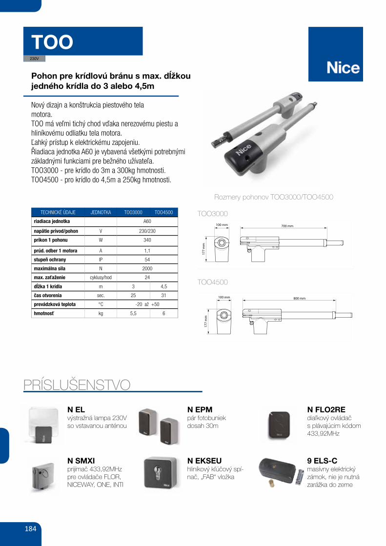
184
TOO
Pohon pre krídlovú bránu s max. dĺžkoujedného krídla do 3 alebo 4,5m
Nový dizajn a konštrukcia piestového telamotora.TOO má veľmi tichý chod vďaka nerezovému piestu a hliníkovému odliatku tela motora.Ľahký prístup k elektrickému zapojeniu.Řiadiaca jednotka A60 je vybavená všetkými potrebnými základnými funkciami pre bežného užívateľa.TOO3000 - pre krídlo do 3m a 300kg hmotnosti.TOO4500 - pro krídlo do 4,5m a 250kg hmotnosti.
TECHNICKÉ ÚDAJE JEDNOTKA TOO3000 TOO4500
riadiaca jednotka A60
napätie prívod/pohon V 230/230
príkon 1 pohonu W 340
prúd. odber 1 motora A 1,1
stupeň ochrany IP 54
maximálna sila N 2000
max. zaťaženie cyklusy/hod 24
dĺžka 1 krídla m 3 4,5
čas otvorenia sec. 25 31
prevádzková teplota °C -20 až +50
hmotnosť kg 5,5 6
PRÍSLUŠENSTVO
N ELvýstražná lampa 230Vso vstavanou anténou
N SMXIprijímač 433,92MHzpre ovládače FLOR, NICEWAY, ONE, INTI
N EPMpár fotobuniekdosah 30m
N FLO2REdiaľkový ovládačs plávajúcim kódom 433,92MHz
9 ELS-Cmasívny elektrický zámok, nie je nutná zarážka do zeme
Rozmery pohonov TOO3000/TOO4500
TOO3000
TOO4500
N EKSEUhliníkový kľúčový spí-nač, „FAB“ vložka
230V
II
1
800 mm100 mm
177
mm
700 mm100 mm
177
mm
2TOO4500 / TOO4524
TOO3000 / TOO3024
II
1
800 mm100 mm
177
mm
700 mm100 mm
177
mm
2TOO4500 / TOO4524
TOO3000 / TOO3024
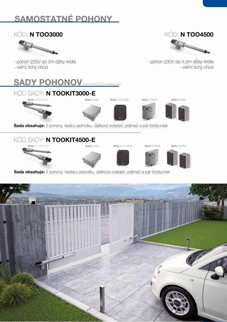
185
SAMOSTATNÉ POHONY
- pohon 230V do 3m dĺžky krídla- veľmi tichý chod
- pohon 230V do 4,5m dĺžky krídla- veľmi tichý chod
SADY POHONOV (do 2/4/3,5/7m prejezdu)
KÓD SADY: N TOOKIT3000-E
Sada obsahuje: 2 pohony, riadicu jednotku, diaľkový ovládač, prijímač a pár fotobuniek
Kód: N TOO3000 Kód: N FLO2RE Kód: N SMXI
KÓD SADY: N TOOKIT4500-EKód: N EPM
KÓD: N TOO3000 KÓD: N TOO4500
Sada obsahuje: 2 pohony, riadiacu jednotku, diaľkový ovládač, prijímač a pár fotobuniek
Kód: N TOO4500 Kód: N FLO2RE Kód: N SMXIKód: N A60
Kód: N A60 Kód: N EPM
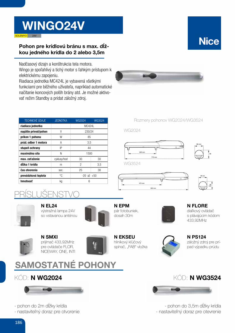
186
WINGO24V
Pohon pre krídlovú bránu s max. dĺž-kou jedného krídla do 2 alebo 3,5m
Nadčasový dizajn a konštrukcia tela motora.Wingo je spoľahlivý a tichý motor s ľahkým prístupom k elektrickému zapojeniu.Riadiaca jednotka MC424L je vybavená všetkými funkciami pre běžného užívateľa, napríklad automatické načítanie koncových polôh brány atd. Je možné aktivo-vať režim Standby a pridat záložný zdroj.
TECHNICKÉ ÚDAJE JEDNOTKA WG2024 WG3524
riadiaca jednotka MC424L
napätie prívod/pohon V 230/24
príkon 1 pohonu W 85
prúd. odber 1 motora A 3,5
stupeň ochrany IP 44
maximálna sila N 1500
max. zaťaženie cyklusy/hod 30 30
dĺžka 1 krídla m 2 3,5
čas otvorenia sec. 25 38
prevádzková teplota °C -20 až +50
hmotnosť kg 6
PRÍSLUŠENSTVON EL24výstražná lampa 24Vso vstavanou anténou
N SMXIprijímač 433,92MHzpre ovládače FLOR, NICEWAY, ONE, INTI
N EPMpár fotobuniek,dosah 30m
N FLOREdiaľkový ovládačs plávajúcim kódom 433,92MHz
N PS124záložný zdroj pre prí-pad výpadku prúdu
XII
1
a
b c d
e
d
2
WG4024 - WG4000 - WG4000/V1
98 mm
770 mm
320 mm
WG5024 - WG5000 - WG5000/V1
98 mm
920 mm
470 mm
95 mm
95mm
Rozmery pohonov WG2024/WG3524
SAMOSTATNÉ POHONY
- pohon do 2m dĺžky krídla- nastaviteľný doraz pre otvorenie
- pohon do 3,5m dĺžky krídla- nastaviteľný doraz pre otevrenie
KÓD: N WG2024 KÓD: N WG3524
XII
1
a
b c d
e
d
2
WG4024 - WG4000 - WG4000/V1
98 mm
770 mm
320 mm
WG5024 - WG5000 - WG5000/V1
98 mm
920 mm
470 mm
95 mm
95mm
WG2024
WG3524
N EKSEUhliníkový kľúčovýspínač, „FAB“ vložka
SOLEMYO 24V
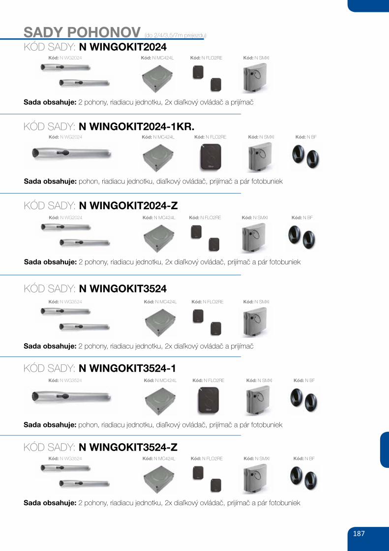
187
SADY POHONOV (do 2/4/3,5/7m prejezdu)
KÓD SADY: N WINGOKIT2024
Sada obsahuje: 2 pohony, riadiacu jednotku, 2x diaľkový ovládač a prijímač
Kód: N WG2024 Kód: N FLO2RE Kód: N SMXI
KÓD SADY: N WINGOKIT2024-1KR.
KÓD SADY: N WINGOKIT2024-Z
Kód: N BF
KÓD SADY: N WINGOKIT3524
KÓD SADY: N WINGOKIT3524-1
KÓD SADY: N WINGOKIT3524-Z
Sada obsahuje: pohon, riadiacu jednotku, diaľkový ovládač, prijímač a pár fotobuniek
Kód: N WG2024 Kód: N FLO2RE Kód: N SMXI
Kód: N BF
Sada obsahuje: pohon, riadiacu jednotku, diaľkový ovládač, prijímač a pár fotobuniek
Kód: N WG3524 Kód: N FLO2RE Kód: N SMXI
Sada obsahuje: 2 pohony, riadiacu jednotku, 2x diaľkový ovládač, prijímač a pár fotobuniek
Kód: N WG2024 Kód: N SMXI Kód: N BFKód: N FLO2RE
Sada obsahuje: 2 pohony, riadiacu jednotku, 2x diaľkový ovládač a prijímač
Kód: N WG3524 Kód: N FLO2RE Kód: N SMXI
Sada obsahuje: 2 pohony, riadiacu jednotku, 2x diaľkový ovládač, prijímač a pár fotobuniek
Kód: N WG3524 Kód: N SMXI Kód: N BFKód: N FLO2RE
Kód: N MC424L
Kód: N MC424L
Kód: N MC424L
Kód: N MC424L
Kód: N MC424L
Kód: N MC424L
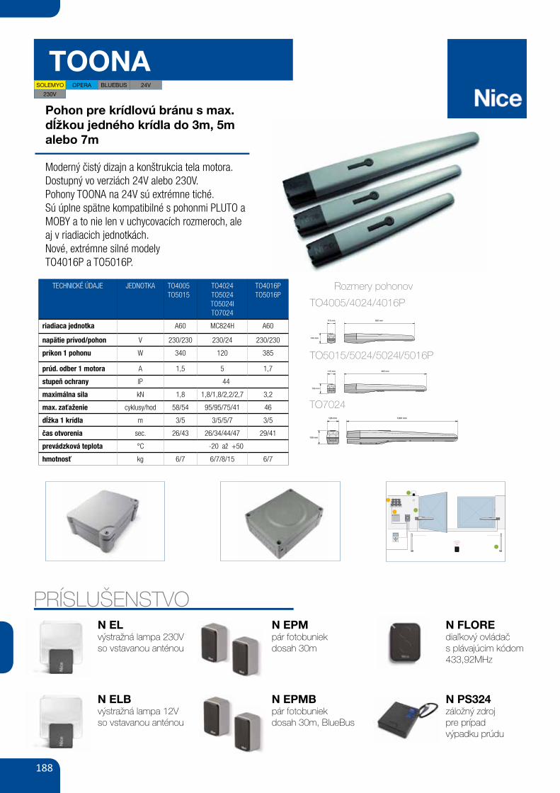
188
TOONA
Pohon pre krídlovú bránu s max. dĺžkou jedného krídla do 3m, 5m alebo 7m
Moderný čistý dizajn a konštrukcia tela motora.Dostupný vo verziách 24V alebo 230V.Pohony TOONA na 24V sú extrémne tiché.Sú úplne spätne kompatibilné s pohonmi PLUTO a MOBY a to nie len v uchycovacích rozmeroch, ale aj v riadiacich jednotkách.Nové, extrémne silné modelyTO4016P a TO5016P.
TECHNICKÉ ÚDAJE JEDNOTKA TO4005TO5015
TO4024TO5024TO5024ITO7024
TO4016PTO5016P
riadiaca jednotka A60 MC824H A60
napätie prívod/pohon V 230/230 230/24 230/230
príkon 1 pohonu W 340 120 385
prúd. odber 1 motora A 1,5 5 1,7
stupeň ochrany IP 44
maximálna sila kN 1,8 1,8/1,8/2,2/2,7 3,2
max. zaťaženie cyklusy/hod 58/54 95/95/75/41 46
dĺžka 1 krídla m 3/5 3/5/5/7 3/5
čas otvorenia sec. 26/43 26/34/44/47 29/41
prevádzková teplota °C -20 až +50
hmotnosť kg 6/7 6/7/8/15 6/7
PRÍSLUŠENSTVON ELvýstražná lampa 230Vso vstavanou anténou
N ELBvýstražná lampa 12Vso vstavanou anténou
N EPMpár fotobuniekdosah 30m
N EPMBpár fotobuniekdosah 30m, BlueBus
N FLOREdiaľkový ovládačs plávajúcim kódom 433,92MHz
N PS324záložný zdrojpre prípadvýpadku prúdu
XIV
3
2
Toona 4
Toona 5
Toona 7
115 mm 820 mm
105 mm
115 mm 965 mm
105 mm
128 mm 1200 mm
150 mm
11 7
22
68
4433
6
Rozmery pohonov
XIV
3
2
Toona 4
Toona 5
Toona 7
115 mm 820 mm
105 mm
115 mm 965 mm
105 mm
128 mm 1200 mm
150 mm
11 7
22
68
4433
6
XIV
3
2
Toona 4
Toona 5
Toona 7
115 mm 820 mm
105 mm
115 mm 965 mm
105 mm
128 mm 1200 mm
150 mm
11 7
22
68
4433
6
TO7024
TO5015/5024/5024I/5016P
TO4005/4024/4016P
230V
SOLEMYO OPERA BLUEBUS 24V
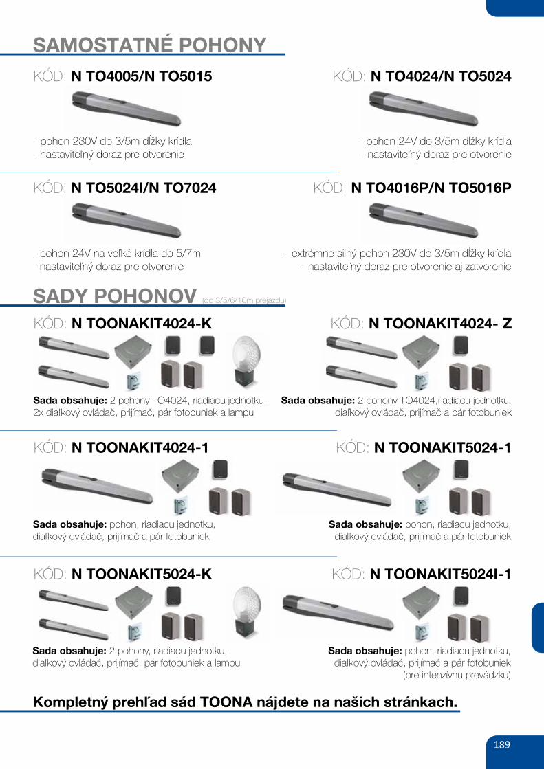
189
SAMOSTATNÉ POHONY
- pohon 230V do 3/5m dĺžky krídla- nastaviteľný doraz pre otvorenie
- pohon 24V do 3/5m dĺžky krídla- nastaviteľný doraz pre otvorenie
SADY POHONOV (do 3/5/6/10m prejazdu)
KÓD: N TO4005/N TO5015 KÓD: N TO4024/N TO5024
- pohon 24V na veľké krídla do 5/7m- nastaviteľný doraz pre otvorenie
- extrémne silný pohon 230V do 3/5m dĺžky krídla- nastaviteľný doraz pre otvorenie aj zatvorenie
KÓD: N TO5024I/N TO7024 KÓD: N TO4016P/N TO5016P
Sada obsahuje: 2 pohony TO4024, riadiacu jednotku,2x diaľkový ovládač, prijímač, pár fotobuniek a lampu
Sada obsahuje: 2 pohony TO4024,riadiacu jednotku,diaľkový ovládač, prijímač a pár fotobuniek
KÓD: N TOONAKIT4024-K KÓD: N TOONAKIT4024- Z
KÓD: N TOONAKIT4024-1 KÓD: N TOONAKIT5024-1
KÓD: N TOONAKIT5024-K KÓD: N TOONAKIT5024I-1
Sada obsahuje: pohon, riadiacu jednotku,diaľkový ovládač, prijímač a pár fotobuniek
Sada obsahuje: pohon, riadiacu jednotku,diaľkový ovládač, prijímač a pár fotobuniek
Sada obsahuje: 2 pohony, riadiacu jednotku,diaľkový ovládač, prijímač, pár fotobuniek a lampu
Sada obsahuje: pohon, riadiacu jednotku,diaľkový ovládač, prijímač a pár fotobuniek
(pre intenzívnu prevádzku)
Kompletný prehľad sád TOONA nájdete na našich stránkach.
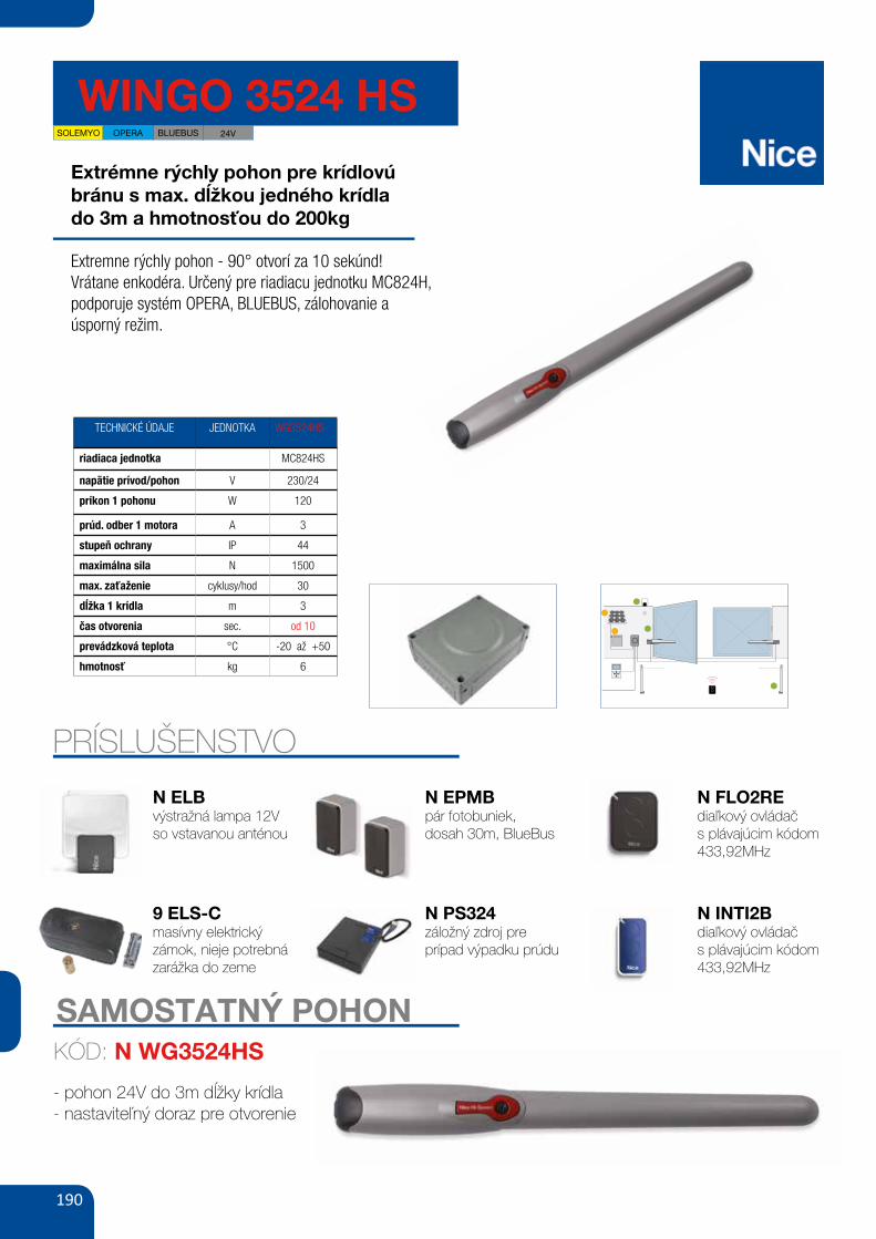
190
WINGO 3524 HS
Extrémne rýchly pohon pre krídlovúbránu s max. dĺžkou jedného krídlado 3m a hmotnosťou do 200kg
Extremne rýchly pohon - 90° otvorí za 10 sekúnd!Vrátane enkodéra. Určený pre riadiacu jednotku MC824H, podporuje systém OPERA, BLUEBUS, zálohovanie a úsporný režim.
TECHNICKÉ ÚDAJE JEDNOTKA WG3524HS
riadiaca jednotka MC824HS
napätie prívod/pohon V 230/24
príkon 1 pohonu W 120
prúd. odber 1 motora A 3
stupeň ochrany IP 44
maximálna sila N 1500
max. zaťaženie cyklusy/hod 30
dĺžka 1 krídla m 3
čas otvorenia sec. od 10
prevádzková teplota °C -20 až +50
hmotnosť kg 6
PRÍSLUŠENSTVO
N ELBvýstražná lampa 12Vso vstavanou anténou
9 ELS-Cmasívny elektrický zámok, nieje potrebná zarážka do zeme
N EPMBpár fotobuniek,dosah 30m, BlueBus
N PS324záložný zdroj preprípad výpadku prúdu
N FLO2REdiaľkový ovládačs plávajúcim kódom 433,92MHz
N INTI2Bdiaľkový ovládačs plávajúcim kódom 433,92MHz
24V
SAMOSTATNÝ POHON
- pohon 24V do 3m dĺžky krídla- nastaviteľný doraz pre otvorenie
KÓD: N WG3524HS
BLUEBUSOPERASOLEMYO
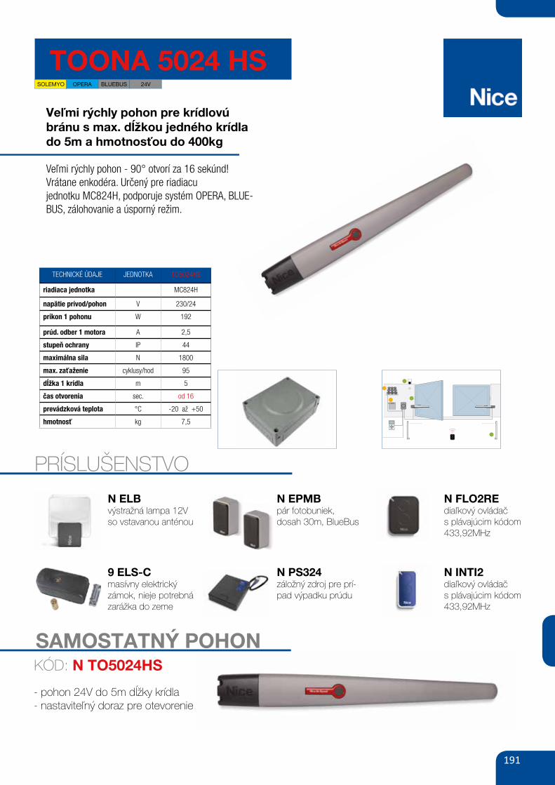
191
TOONA 5024 HS
Veľmi rýchly pohon pre krídlovúbránu s max. dĺžkou jedného krídla do 5m a hmotnosťou do 400kg
Veľmi rýchly pohon - 90° otvorí za 16 sekúnd!Vrátane enkodéra. Určený pre riadiacujednotku MC824H, podporuje systém OPERA, BLUE-BUS, zálohovanie a úsporný režim.
TECHNICKÉ ÚDAJE JEDNOTKA TO5024HS
riadiaca jednotka MC824H
napätie prívod/pohon V 230/24
príkon 1 pohonu W 192
prúd. odber 1 motora A 2,5
stupeň ochrany IP 44
maximálna sila N 1800
max. zaťaženie cyklusy/hod 95
dĺžka 1 krídla m 5
čas otvorenia sec. od 16
prevádzková teplota °C -20 až +50
hmotnosť kg 7,5
PRÍSLUŠENSTVO
SOLEMYO OPERA BLUEBUS 24V
SAMOSTATNÝ POHON
- pohon 24V do 5m dĺžky krídla- nastaviteľný doraz pre otevorenie
KÓD: N TO5024HS
N ELBvýstražná lampa 12Vso vstavanou anténou
9 ELS-Cmasívny elektrický zámok, nieje potrebná zarážka do zeme
N EPMBpár fotobuniek,dosah 30m, BlueBus
N PS324záložný zdroj pre prí-pad výpadku prúdu
N FLO2REdiaľkový ovládačs plávajúcim kódom 433,92MHz
N INTI2diaľkový ovládačs plávajúcim kódom 433,92MHz
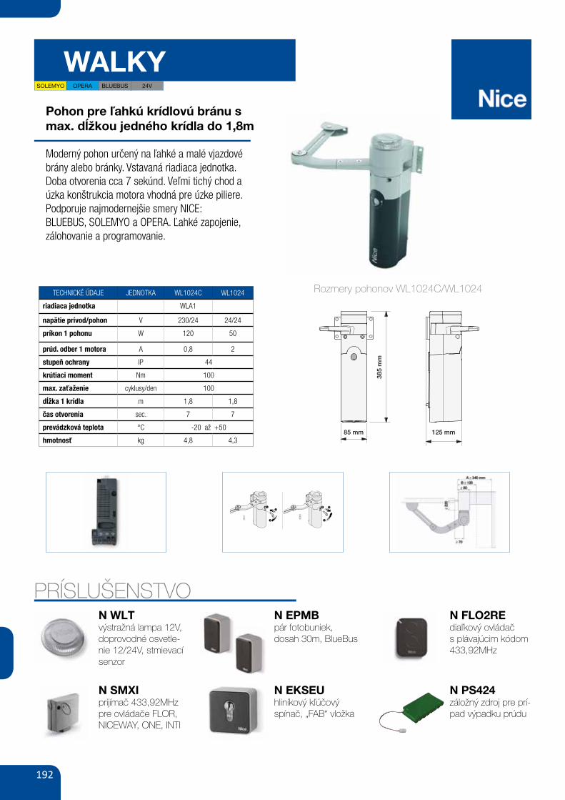
192
WALKY
Pohon pre ľahkú krídlovú bránu s max. dĺžkou jedného krídla do 1,8m
Moderný pohon určený na ľahké a malé vjazdové brány alebo bránky. Vstavaná riadiaca jednotka.Doba otvorenia cca 7 sekúnd. Veľmi tichý chod a úzka konštrukcia motora vhodná pre úzke piliere.Podporuje najmodernejšie smery NICE:BLUEBUS, SOLEMYO a OPERA. Ľahké zapojenie, zálohovanie a programovanie.
TECHNICKÉ ÚDAJE JEDNOTKA WL1024C WL1024
riadiaca jednotka WLA1
napätie prívod/pohon V 230/24 24/24
príkon 1 pohonu W 120 50
prúd. odber 1 motora A 0,8 2
stupeň ochrany IP 44
krútiaci moment Nm 100
max. zaťaženie cyklusy/den 100
dĺžka 1 krídla m 1,8 1,8
čas otvorenia sec. 7 7
prevádzková teplota °C -20 až +50
hmotnosť kg 4,8 4,3
PRÍSLUŠENSTVON WLTvýstražná lampa 12V, doprovodné osvetle-nie 12/24V, stmievací senzor
N SMXIprijímač 433,92MHzpre ovládače FLOR, NICEWAY, ONE, INTI
N EPMBpár fotobuniek,dosah 30m, BlueBus
N FLO2REdiaľkový ovládačs plávajúcim kódom 433,92MHz
N PS424záložný zdroj pre prí-pad výpadku prúdu
X
1
2
2a
385
mm
125 mm85 mm
Rozmery pohonov WL1024C/WL1024
N EKSEUhliníkový kľúčovýspínač, „FAB“ vložka
XIX
12
3 1
3 2
BA
22
7 8 9
10 11-A 11-B
12 13 14
SOLEMYO OPERA BLUEBUS 24V
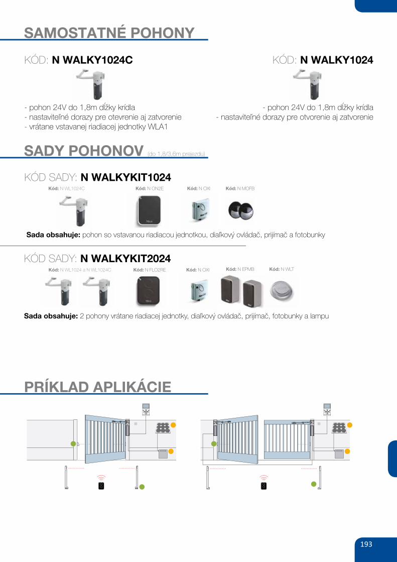
193
SAMOSTATNÉ POHONY
- pohon 24V do 1,8m dĺžky krídla- nastaviteľné dorazy pre otevrenie aj zatvorenie- vrátane vstavanej riadiacej jednotky WLA1
- pohon 24V do 1,8m dĺžky krídla- nastaviteľné dorazy pre otvorenie aj zatvorenie
SADY POHONOV (do 1,8/3,6m prejezdu)
KÓD SADY: N WALKYKIT1024
Sada obsahuje: pohon so vstavanou riadiacou jednotkou, diaľkový ovládač, prijímač a fotobunky
Kód: N WL1024C Kód: N ON2E Kód: N OXI Kód: N MOFB
KÓD SADY: N WALKYKIT2024
Sada obsahuje: 2 pohony vrátane riadiacej jednotky, diaľkový ovládač, prijímač, fotobunky a lampu
Kód: N WL1024 a N WL1024C Kód: N FLO2RE Kód: N OXI Kód: N EPMB Kód: N WLT
KÓD: N WALKY1024C KÓD: N WALKY1024
PRÍKLAD APLIKÁCIE
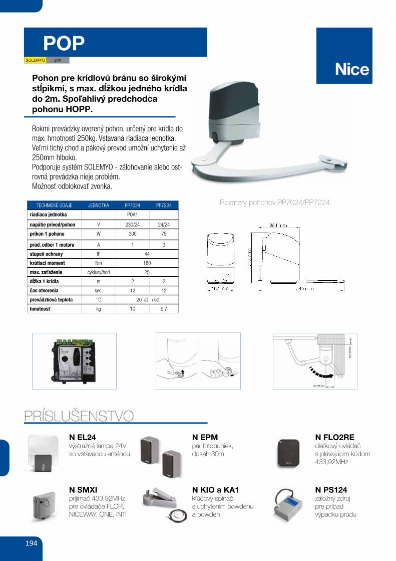
194
POP
Parametry
Zasilanie/zasilanie silnikaNatężenie prądu
Stopień zabezpieczenia
Moment obrotowy
Prędkość obrotowa
Ciężar
(V)
(A)
(W)
(IP)
(Nm)
(obr./min.)
(°C min./max.)
(%)
(kg)
PP7024 PP7224
230/241.0
7544
1801.26-1.68
-20 do +5030
10.0
243.0
30044
1801.26-1.68
-20 do +50309.7
Temperatura pracyIntensywność pracy
Moc pobierana
zestaw do bram dwuskrzydłowych: siłownik samohamowny PP7024 z ramieniem łamanym, silnik 24V, z wbudowaną centralą sterującą POA1,
siłownik samohamowny PP7224, radioodbiornik OXI, 1 pilot dwukanałowy FLO2RE, fotokomórki BF
POP ERA FLOR
cena netto cena bruttoKod2 829,002 300,00
zestaw do bram dwuskrzydłowych: siłownik samohamowny PP7024 z ramieniem łamanym, silnik 24V, z wbudowaną centralą sterującą POA1,
siłownik samohamowny PP7224, radioodbiornik OXI, 2 piloty dwukanałowe SM2, fotokomórki BF
POP SMILO 2 952,002 400,00
PP7224 samohamowny siłownik, silnik 24 V, z ramieniem łamanym
PP7024 samohamowny siłownik, silnik 24 V, z ramieniem łamanym, wbudowana centrala sterująca POA1 1 660,50
1 537,50
1 350,00
1 250,00
POP
24VBLUEBUSOPERASOLEMYO
Wygodny: funkcja częściowego otwarcia bramy lub jednego
skrzydła w standardzie (funkcja furtki).
tylko trzy przyciski programowania, regulacjaZaawansowany:
trybu pracy, czasu otwierania, itp., diody LED sygnalizują
włączone funkcje.
siłowniki w czasie programowania automatycznieInteligentny:
zapamiętują położenia krańcowe bramy (autoprogramowanie).
Złącze radiowe typu OXI, SMXI, SMXIS.
Fotokomórki typu BF/MOF/FK/F210/FT210.
Solemyo - POP ERA ONE BLUEBUS.
funkcje central strona 74/75
54| AUTOMATYKA DO BRAM SKRZYDŁOWYCH
Pohon pre krídlovú bránu so širokými stĺpikmi, s max. dĺžkou jedného krídlado 2m. Spoľahlivý predchodcapohonu HOPP.
Rokmi prevádzky overený pohon, určený pre krídla do max. hmotnosti 250kg. Vstavaná riadiaca jednotka. Veľmi tichý chod a pákový prevod umožní uchytenie až 250mm hlboko.Podporuje systém SOLEMYO - zálohovanie alebo ost-rovná prevádzka nieje problém.Možnosť odblokovať zvonka.
TECHNICKÉ ÚDAJE JEDNOTKA PP7024 PP7224
riadiaca jednotka POA1
napätie prívod/pohon V 230/24 24/24
príkon 1 pohonu W 300 75
prúd. odber 1 motora A 1 3
stupeň ochrany IP 44
krútiaci moment Nm 180
max. zaťaženie cyklusy/hod 25
dĺžka 1 krídla m 2 2
čas otvorenia sec. 12 12
prevádzková teplota °C -20 až +50
hmotnosť kg 10 9,7
PRÍSLUŠENSTVON EL24výstražná lampa 24Vso vstavanou anténou
N SMXIprijímač 433,92MHzpre ovládače FLOR, NICEWAY, ONE, INTI
N EPMpár fotobuniek,dosah 30m
N FLO2REdiaľkový ovládačs plávajúcim kódom 433,92MHz
N PS124záložný zdrojpre prípadvýpadku prúdu
2
1
3
2
1
3
Rozmery pohonov PP7024/PP7224
N KIO a KA1kľúčový spínačs uchytením bowdenu a bowden
8 9
10 A B
11
4
1
6
75
2
3
12
SOLEMYO 24V
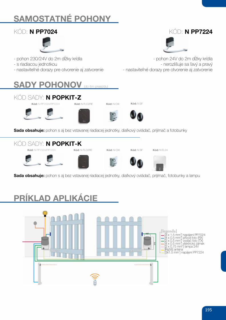
195
SAMOSTATNÉ POHONY
- pohon 230/24V do 2m dĺžky krídla- s riadiacou jednotkou- nastaviteľné dorazy pre otvorenie aj zatvorenie
- pohon 24V do 2m dĺžky krídla- nerozlišuje sa ľavý a pravý
- nastaviteľné dorazy pre otvorenie aj zatvorenie
SADY POHONOV (do 4m prejezdu)
KÓD SADY: N POPKIT-K
Sada obsahuje: pohon s aj bez vstavanej riadiacej jednotky, diaľkový ovládač, prijímač, fotobunky a lampu
Kód: N PP7024/PP7224 Kód: N FLO2RE Kód: N OXI Kód: N BF
KÓD SADY: N POPKIT-Z
Sada obsahuje: pohon s aj bez vstavanej riadiacej jednotky, diaľkový ovládač, prijímač a fotobunky
Kód: N PP7024/PP7224 Kód: N FLO2RE Kód: N OXI Kód: N BF
Kód: N EL24
KÓD: N PP7024 KÓD: N PP7224
BF LUCY24 ML24fotokomórki (para)
zasięg 15-30 m
lampa sygnalizacyjna 24V lampa sygnalizacyjna 24V
z wbudowaną anteną 433.92 MHz160,00
196,80 brutto
100,00
123,00 brutto
130,00
159,90 brutto
AKCESORIA
167
310
[3 x 1.5 mm ] PP70242
napájení[4 x 0.5 mm ] (RX)
2přívod foto
[4 x 0.5 mm ]2
elektrický zámek[2 x 0.75 mm ] lampa 24V
2
[Rg58] ant naé
[legenda]
[2 x 0.5 mm ] foto (TX)2
vysílač
[3x1.5 mm ] PP72242
napájení
250
PARAMETRY SKRZYDŁA BRAMY
PS124akumulator 24V 1.2 Ah
z wbudowaną kartą ładowania290,00
356,70 brutto
190,00
233,70 brutto
KIOkluczykowe wysprzęglenie
z zewnątrz za pomocą linki
PLA 10 PLA 11zamek elektromagnetyczny pionowyzamek elektromagnetyczny poziomy
340,00
418,20 brutto
340,00
418,20 brutto
|55AUTOMATYKA DO BRAM SKRZYDŁOWYCH
FLO2RE1 pilot dwukanałowy
433.92 MHz
OXI BFradioodbiornik wewnętrzny,
4-kanałowy 433.92 MHz
fotokomórkiPOP ERA FLOR2 siłowniki do bram o długości do 2.0 m
PRZYKŁADOWY ZESTAW DO UŻYTKU PRZYDOMOWEGO
POZOSTAŁE AKCESORIA STR. 96-105
KA1linka 6 m do KIO
60,00
73,80 brutto
SOLEMYO (SYKCE)
1 350,00
1 660,50 brutto
zestaw zasilania słonecznego
PRÍKLAD APLIKÁCIE
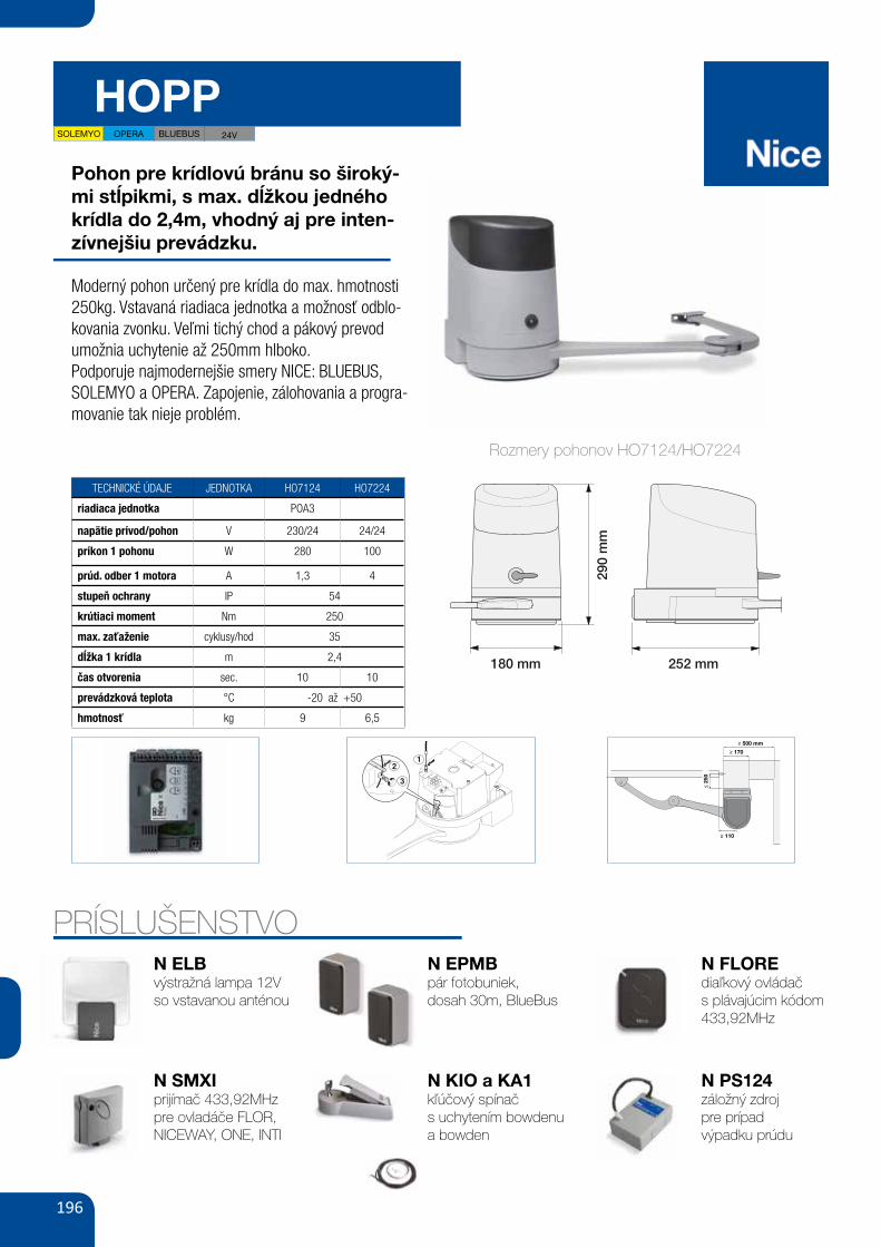
196
HOPP
Pohon pre krídlovú bránu so široký-mi stĺpikmi, s max. dĺžkou jedného krídla do 2,4m, vhodný aj pre inten-zívnejšiu prevádzku.
Moderný pohon určený pre krídla do max. hmotnosti 250kg. Vstavaná riadiaca jednotka a možnosť odblo-kovania zvonku. Veľmi tichý chod a pákový prevod umožnia uchytenie až 250mm hlboko.Podporuje najmodernejšie smery NICE: BLUEBUS, SOLEMYO a OPERA. Zapojenie, zálohovania a progra-movanie tak nieje problém.
TECHNICKÉ ÚDAJE JEDNOTKA HO7124 HO7224
riadiaca jednotka POA3
napätie prívod/pohon V 230/24 24/24
príkon 1 pohonu W 280 100
prúd. odber 1 motora A 1,3 4
stupeň ochrany IP 54
krútiaci moment Nm 250
max. zaťaženie cyklusy/hod 35
dĺžka 1 krídla m 2,4
čas otvorenia sec. 10 10
prevádzková teplota °C -20 až +50
hmotnosť kg 9 6,5
PRÍSLUŠENSTVON ELBvýstražná lampa 12Vso vstavanou anténou
N SMXIprijímač 433,92MHzpre ovladáče FLOR, NICEWAY, ONE, INTI
N EPMBpár fotobuniek,dosah 30m, BlueBus
N KIO a KA1kľúčový spínačs uchytením bowdenu a bowden
N FLOREdiaľkový ovládačs plávajúcim kódom 433,92MHz
N PS124záložný zdrojpre prípadvýpadku prúdu
50 GATE&DOOR 2013
1 1,2 1,4 1,6 1,8 2 2,2 2,4
250
225
200
175
≥ 170
≥ 110
≥ 500 mm
≤ 25
0
290
180 mm
25216
3
24VbLuEbusOPERAsOLEmyO
hOPP
hO7124 hO7224
230 -- 24
1.3 4280 100
1.6825035
54-20 ÷ +50
252x180x290 h9 6.5
TEChNICAL sPECIFICATIONsCODEELECTRICAL DATAPOWER SUPPLY (Vac 50/60 Hz)POWER SUPPLY (Vdc)ABSORPTION (A)POWER (W)PERFORmANCE DATASPEED (rpm)TORqUE (Nm)WORK CYCLE (CYCLES/HOUR)DImENsIONAL AND GENERAL DATAPROTECTION LEVEL (IP)WORKING TEMP. (°C MIN/MAx)DIMENSIONS (mm)WEIGHT (kg)
* Version without control unit, only if associated with PP7124
mAx
. GAT
E W
EIGh
T (k
G)
mAx. GATE LENGTh (m)
The shape, the height of the gate and the weather conditions can considerably reduce the values shown in the graph to the side.
CODE DESCRIPTION PACK/PALLET
hO7124 IRREVERSIBLE 24 Vdc, COMPLETE WITH ARTICULATED ARM AND BUILT-IN CONTROL UNIT
12
hO7224 IRREVERSIBLE 24 Vdc, COMPLETE WITH ARTICULATED ARM WITHOUT CONTROL UNIT
12
N.b. The content of the package may vary: consult the retailer.
uTILIsATION LImITs DImENsIONs
BUILT-IN CONTROL UNIT
DIE CAST ALUMINIUMHOUSING
UNLOCK SYSTEM WITH METAL KEY. DESIGNED TO ACCOMMODATE ExTERNAL RELEASE TOO, THANKS KIO ACCESSORY
For swing gates with leaves up to 2.4 m, ideal for large columns. Irreversible electromechanical 24 Vdc gear motor with articulated arm, surface mounted. Ideal for intensive use. Two irreversible 24 Vdc motors with micrometric adjustment mechanical stops on opening and closing: with built-in control unit (HO7124) and without control unit (HO7224).
Powerful thanks to the 250 Nm torque.
Resistant and compact: 180 mm in width, ideal for any kind of post. Small shockproof body with aluminium base.
sturdy, aluminium anti-shearing arm.
Easy to install: thanks to the new fixing bracket with quick connector for the motor. No welding.
sophisticated electronics with the built-in control unit, just 3 keys to manage all programming operations:
• obstacle detection and possibility of connecting to 8.2 KOhm sensitive edge, fototest; • automatic fault diagnostics; • memorisation of opening and closing travel limits in self-learning mode; • possibility of configuring the stop input in self-learning mode, NO, NC and the latest generation 8.2 KOhm resistive sensitive edges: • deceleration on opening and closing; • simple connection of pairs of additional photocells, foto2; • programming of pause time; • pedestrian open and partial open; • clutch with anti-crushing safety mechanism.
Energy saving with no black outs: 3 standby modes to reduce mains consumption, or battery power consumption if connected to the Solemyo kit. Operation in the event of a power failure thanks to the optional batteries (PS124).
Everything under control: thanks to compatibility for operation with Opera system BUS T4, the unit can be used to expand the options of programming, control and diagnostics of the automation on site and remotely.
2
1 2
290
mm
180 mm
MIN 400 mm
252 mm
3
4
Rozmery pohonov HO7124/HO7224
1
2
12
3
19 1 3
5
2
4
3
2
16 7
SOLEMYO OPERA BLUEBUS 24V
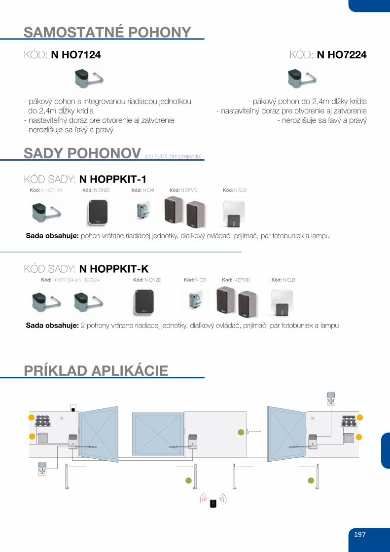
197
SAMOSTATNÉ POHONY
- pákový pohon s integrovanou riadiacou jednotkou do 2,4m dĺžky krídla- nastaviteľný doraz pre otvorenie aj zatvorenie- nerozlišuje sa ľavý a pravý
- pákový pohon do 2,4m dĺžky krídla- nastaviteľný doraz pre otvorenie aj zatvorenie
- nerozlišuje sa ľavý a pravý
SADY POHONOV (do 2,4/4,8m prejezdu)
KÓD SADY: N HOPPKIT-1
Sada obsahuje: pohon vrátane riadiacej jednotky, diaľkový ovládač, prijímač, pár fotobuniek a lampu
Kód: N HO7124 Kód: N ON2E Kód: N OXI Kód: N EPMB Kód: N ELB
KÓD: N HO7124 KÓD: N HO7224
PRÍKLAD APLIKÁCIE
KÓD SADY: N HOPPKIT-K
Sada obsahuje: 2 pohony vrátane riadiacej jednotky, diaľkový ovládač, prijímač, pár fotobuniek a lampu
Kód: N HO7124 a N HO7224 Kód: N ON2E Kód: N OXI Kód: N EPMB Kód: N ELB
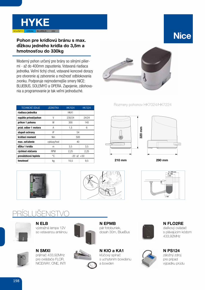
198
HYKE
Pohon pre krídlovú bránu s max. dĺžkou jedného krídla do 3,5m a hmotnosťou do 330kg
Moderný pohon určený pre brány so silnými pilier-mi - až do 400mm zapustenia. Vstavaná riadiaca jednotka. Veľmi tichý chod, vstavané koncové dorazy pre otvorenie aj zatvorenie a možnosť odblokovania zvonku. Podporuje nejmodernejšie smery NICE:BLUEBUS, SOLEMYO a OPERA. Zapojenie, zálohova-nia a programovanie je tak veľmi jednoduché.
TECHNICKÉ ÚDAJE JEDNOTKA HK7024 HK7224
riadiaca jednotka HKA1
napätie prívod/pohon V 230/24 24/24
príkon 1 pohonu W 300 140
prúd. odber 1 motora A 1,5 6
stupeň ochrany IP 54
krútiaci moment Nm 500
max. zaťaženie cyklusy/hod 40
dĺžka 1 krídla m 3,5 3,5
rýchlost otáčania RPM 2,25 2,25
prevádzková teplota °C -20 až +50
hmotnosť kg 10,5 9,5
PRÍSLUŠENSTVON ELBvýstražná lampa 12Vso vstavanou anténou
N SMXIprijímač 433,92MHzpre ovládače FLOR, NICEWAY, ONE, INTI
N EPMBpár fotobuniek,dosah 30m, BlueBus
N FLO2REdiaľkový ovládačs plávajúcim kódom 433,92MHz
N PS124záložný zdrojpre prípadvýpadku prúdu
54 GATE&DOOR 2013
≥ 150
≤ 40
0
≥ 210B ≥ 300A ≥ 650 mm
330
300
250
200
150
1.8 2.52 3 3.5
b
A
210 mm
320
665
480
290
hykE24VbLuEbusOPERAsOLEmyO
hk7024 hk7224
230 -- 24
1.5 6300 140
2.2550040
54-20 ÷ +50
290x210x320 h10.5 9.5
For swing gates with leaves up to 3.5 m, ideal for large columns. Irreversible electromechanical 24 Vdc gearmotor with articulated arm, surface mounted. Ideal for intensive use.
Reliable, durability thanks to the housing in aluminium with polyester paint finish, resistant to atmospheric agents.
ultra-powerful and delicate: thanks to the torque of 500 Nm and encoder technology, for millimetric precision and reliability. Safety in movement with dual technology obstacle detection.
Two irreversible 24 Vdc versions with limit switches on opening and closing: with built-in control unit (HK7024) and without control unit (HK7224).
Practical and quick installation: the articulated arm is adjustable in length for maximum flexibility.
simple and precise limit switch adjustment: mechanical stops and micrometric adjustment screws.
Easy to operate release lever, with metal lock and personalised Nice key. With provision for cable control.
savings, respect for the environment, and autonomy: when connected to the buffer battery or Solemyo kit, consumption on standby is just 0.1 W.
No black out: with the optional batteries (PS124) housed inside the gear motor.
built-in control unit (hk7024): • simple programming via a single key; • self-learning of opening and closing limit positions; • automatic fault diagnostics; • pause time programming; • pass door; • deceleration on opening and closing; • obstacle detection with dual technology; • provision for connection of latest generation sensitive edges.
CODE DESCRIPTION PACK/PALLET
hk7024 IRREVERSIBLE 24 Vdc, COMPLETE WITH ARTICULATED ARMAND BUILT-IN CONTROL UNIT
12
hk7224 IRREVERSIBLE 24 Vdc, COMPLETE WITH ARTICULATED ARMWITHOUT CONTROL UNIT
12
TEChNICAL sPECIFICATIONsCODEELECTRICAL DATAPOWER SUPPLY (Vac 50/60 Hz)POWER SUPPLY (Vdc)ABSORPTION (A)POWER (W)PERFORmANCE DATASPEED (rpm)TORqUE (Nm)WORK CYCLE (CYCLES/HOUR)DImENsIONAL AND GENERAL DATAPROTECTION LEVEL (IP)WORKING TEMP. (°C MIN/MAx)DIMENSIONS (mm)WEIGHT (kg)
mAx
. GAT
E W
EIGh
T (k
G)
mAx. GATE LENGTh (m)
The shape, the height of the gateand the weather conditions can considerably reduce the values shown in the graph to the side.
A Entire armb Reduced arm
uTILIsATION LImITs DImENsIONs
BUILT-IN CONTROL UNIT
PRACTICAL AND RESISTANTRELEASE HANDLE
DIE CAST ALUMINIUMHOUSING
ADjUSTABLE ANTI-CRUSHING ARM
1 2
3
4
320
mm
210 mm 290 mm
Rozmery pohonov HK7024/HK7224
N KIO a KA1kľúčový spínačs uchytením bowdenu a bowden
21 1 3
5
1
22
4
62
1
3
7
SOLEMYO OPERA BLUEBUS 24V
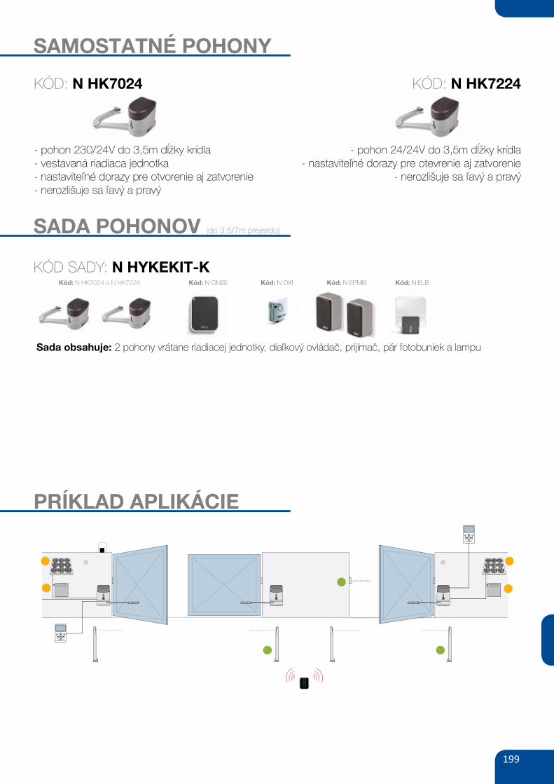
199
SAMOSTATNÉ POHONY
- pohon 230/24V do 3,5m dĺžky krídla- vestavaná riadiaca jednotka- nastaviteľné dorazy pre otvorenie aj zatvorenie- nerozlišuje sa ľavý a pravý
- pohon 24/24V do 3,5m dĺžky krídla- nastaviteľné dorazy pre otevrenie aj zatvorenie
- nerozlišuje sa ľavý a pravý
KÓD: N HK7024 KÓD: N HK7224
SADA POHONOV (do 3,5/7m prejezdu)
PRÍKLAD APLIKÁCIE
KÓD SADY: N HYKEKIT-K
Sada obsahuje: 2 pohony vrátane riadiacej jednotky, diaľkový ovládač, prijímač, pár fotobuniek a lampu
Kód: N HK7024 a N HK7224 Kód: N ON2E Kód: N OXI Kód: N EPMB Kód: N ELB
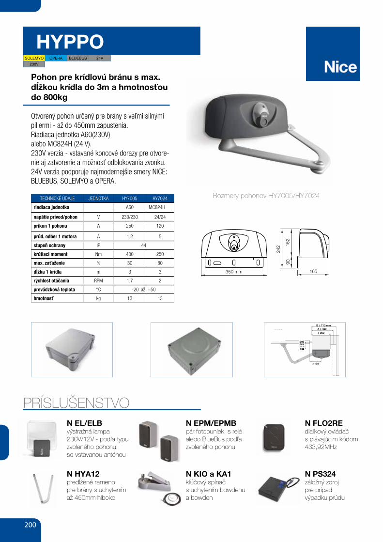
200
HYPPO
Pohon pre krídlovú bránu s max. dĺžkou krídla do 3m a hmotnosťou do 800kg
Otvorený pohon určený pre brány s veľmi silnými piliermi - až do 450mm zapustenia.Riadiaca jednotka A60(230V)alebo MC824H (24 V).230V verzia - vstavané koncové dorazy pre otvore-nie aj zatvorenie a možnosť odblokovania zvonku.24V verzia podporuje najmodernejšie smery NICE: BLUEBUS, SOLEMYO a OPERA.
TECHNICKÉ ÚDAJE JEDNOTKA HY7005 HY7024
riadiaca jednotka A60 MC824H
napätie prívod/pohon V 230/230 24/24
príkon 1 pohonu W 250 120
prúd. odber 1 motora A 1,2 5
stupeň ochrany IP 44
krútiaci moment Nm 400 250
max. zaťaženie % 30 80
dĺžka 1 krídla m 3 3
rýchlost otáčania RPM 1,7 2
prevádzková teplota °C -20 až +50
hmotnosť kg 13 13
PRÍSLUŠENSTVON EL/ELBvýstražná lampa230V/12V - podľa typu zvoleného pohonu,so vstavanou anténou
N HYA12predĺžené ramenopre brány s uchytením až 450mm hlboko
N EPM/EPMBpár fotobuniek, s relé alebo BlueBus podľa zvoleného pohonu
N FLO2REdiaľkový ovládačs plávajúcim kódom 433,92MHz
N PS324záložný zdrojpre prípadvýpadku prúdu
58 GATE&DOOR 2013
≥ 130
≥ 300
B ≥ 710 mmA ≥ 450
B ≤
450
A ≤
350
hyPPO 7000
800
700
600
500
400
300
2002 2,5 3
HY7005
HY7005 / HY7024
165350 mm24
2
9015
2
230V24VbLuEbusOPERAsOLEmyO
hy7024 hy7005
- 23024 -5 1.2
120 250
2 1.7250 40080 30
43-20 ÷ +50
350x165x242 h13
For swing gates with leaves up to 3 m, also ideal for large pillars. Electromechanical gear motor, surface mounted, also in 24 Vdc version with magnetic encoder, with articulated arm.
Single model for right and left leaves. Two irreversible versions, with 230 Vac (HY7005) and 24 Vdc (HY7024) power supplies with magnetic encoder.
Fewer connections mean quicker installation.
Pre-wired, incorporated double limit-switch both during opening and closing (HY7005).
mAx
. GAT
E W
EIGh
T (k
G)
mAx. GATE LENGTh (m)
N.B. The above values are valid if the motor is used with standard accessories. The shape, the height of the gate and the weather conditions can considerably reduce the values shown in the graph to the side. Use in windy areas 230 Vac models.
CODE DESCRIPTION PACK/PALLET
hy7024 IRREVERSIBLE, 24 Vdc, WITH MAGNETIC ENCODER, WITH SHEAR-PROOF ARTICULATED ARM, GALVANIZED AND PAINTED
16
hy7005 IRREVERSIBLE, 230 Vac, WITH STURDY ARTICULATED SHEAR-PROOF ARM, GALVANIZED AND PAINTED, WITH LIMIT SWITCH ON OPENING AND CLOSING
16
Easy and quick to install: thanks to fewer connections and nothing welded to the gates.
Long-lasting: solid metal mechanics.
Compact: shockproof bodywork with no sharp corners.
Recommended control units: Mindy A6F, A60, A700F; for HY7024 Moonclever MC824H.
24 Vdc version with magnetic encoder. Perfect for intensive use, compatible with the control unit Moonclever MC824H: • simple programming, by means of a single key; • self-learning of opening and closing limit positions; • automatic fault diagnostics; • programming of pause time; • pedestrian pass door; • deceleration on opening and closing; • obstacle detection with dual technology; • operation in event of power failure by means of optional rechargeable batteries (PS324); • provision for connection of latest generation resistive sensitive edges.
TEChNICAL sPECIFICATIONsCODEELECTRICAL DATAPOWER SUPPLY (Vac 50 Hz)*POWER SUPPLY (Vdc)ABSORPTION (A)POWER (W)PERFORmANCE DATASPEED (rpm)TORqUE (Nm)WORK CYCLE (%)DImENsIONAL AND GENERAL DATAPROTECTION LEVEL (IP)WORKING TEMP. (°C MIN/MAx)DIMENSIONS (mm)WEIGHT (kg)
*60 Hz version available on request.
A Standard armb Arm with accessory HYA12
uTILIsATION LImITs DImENsIONs
STURDY, ANTI-SHEARING ARM, GALVANISED AND PAINTED; STRENGTHENED IN THOSE AREAS SUBjECTED TO GREATER MECHANICAL STRESS
DIE-CAST, ALUMINIUM, KEY-OPERATED UNLOCK SYSTEM, COMPLETE WITH PROTECTED KEY. DESIGNED TO ACCOMMODATE ExTERNAL RELEASE, TOO
Rozmery pohonov HY7005/HY7024
N KIO a KA1kľúčový spínačs uchytením bowdenu a bowden
58 GATE&DOOR 2013
≥ 130
≥ 300
B ≥ 710 mmA ≥ 450
B ≤
450
A ≤
350
hyPPO 7000
800
700
600
500
400
300
2002 2,5 3
HY7005
HY7005 / HY7024
165350 mm
242
9015
2
230V24VbLuEbusOPERAsOLEmyO
hy7024 hy7005
- 23024 -5 1.2
120 250
2 1.7250 40080 30
43-20 ÷ +50
350x165x242 h13
For swing gates with leaves up to 3 m, also ideal for large pillars. Electromechanical gear motor, surface mounted, also in 24 Vdc version with magnetic encoder, with articulated arm.
Single model for right and left leaves. Two irreversible versions, with 230 Vac (HY7005) and 24 Vdc (HY7024) power supplies with magnetic encoder.
Fewer connections mean quicker installation.
Pre-wired, incorporated double limit-switch both during opening and closing (HY7005).
mAx
. GAT
E W
EIGh
T (k
G)
mAx. GATE LENGTh (m)
N.B. The above values are valid if the motor is used with standard accessories. The shape, the height of the gate and the weather conditions can considerably reduce the values shown in the graph to the side. Use in windy areas 230 Vac models.
CODE DESCRIPTION PACK/PALLET
hy7024 IRREVERSIBLE, 24 Vdc, WITH MAGNETIC ENCODER, WITH SHEAR-PROOF ARTICULATED ARM, GALVANIZED AND PAINTED
16
hy7005 IRREVERSIBLE, 230 Vac, WITH STURDY ARTICULATED SHEAR-PROOF ARM, GALVANIZED AND PAINTED, WITH LIMIT SWITCH ON OPENING AND CLOSING
16
Easy and quick to install: thanks to fewer connections and nothing welded to the gates.
Long-lasting: solid metal mechanics.
Compact: shockproof bodywork with no sharp corners.
Recommended control units: Mindy A6F, A60, A700F; for HY7024 Moonclever MC824H.
24 Vdc version with magnetic encoder. Perfect for intensive use, compatible with the control unit Moonclever MC824H: • simple programming, by means of a single key; • self-learning of opening and closing limit positions; • automatic fault diagnostics; • programming of pause time; • pedestrian pass door; • deceleration on opening and closing; • obstacle detection with dual technology; • operation in event of power failure by means of optional rechargeable batteries (PS324); • provision for connection of latest generation resistive sensitive edges.
TEChNICAL sPECIFICATIONsCODEELECTRICAL DATAPOWER SUPPLY (Vac 50 Hz)*POWER SUPPLY (Vdc)ABSORPTION (A)POWER (W)PERFORmANCE DATASPEED (rpm)TORqUE (Nm)WORK CYCLE (%)DImENsIONAL AND GENERAL DATAPROTECTION LEVEL (IP)WORKING TEMP. (°C MIN/MAx)DIMENSIONS (mm)WEIGHT (kg)
*60 Hz version available on request.
A Standard armb Arm with accessory HYA12
uTILIsATION LImITs DImENsIONs
STURDY, ANTI-SHEARING ARM, GALVANISED AND PAINTED; STRENGTHENED IN THOSE AREAS SUBjECTED TO GREATER MECHANICAL STRESS
DIE-CAST, ALUMINIUM, KEY-OPERATED UNLOCK SYSTEM, COMPLETE WITH PROTECTED KEY. DESIGNED TO ACCOMMODATE ExTERNAL RELEASE, TOO
58 GATE&DOOR 2013
≥ 130
≥ 300
B ≥ 710 mmA ≥ 450
B ≤
450
A ≤
350
hyPPO 7000
800
700
600
500
400
300
2002 2,5 3
HY7005
HY7005 / HY7024
165350 mm24
2
9015
2
230V24VbLuEbusOPERAsOLEmyO
hy7024 hy7005
- 23024 -5 1.2
120 250
2 1.7250 40080 30
43-20 ÷ +50
350x165x242 h13
For swing gates with leaves up to 3 m, also ideal for large pillars. Electromechanical gear motor, surface mounted, also in 24 Vdc version with magnetic encoder, with articulated arm.
Single model for right and left leaves. Two irreversible versions, with 230 Vac (HY7005) and 24 Vdc (HY7024) power supplies with magnetic encoder.
Fewer connections mean quicker installation.
Pre-wired, incorporated double limit-switch both during opening and closing (HY7005).
mAx
. GAT
E W
EIGh
T (k
G)
mAx. GATE LENGTh (m)
N.B. The above values are valid if the motor is used with standard accessories. The shape, the height of the gate and the weather conditions can considerably reduce the values shown in the graph to the side. Use in windy areas 230 Vac models.
CODE DESCRIPTION PACK/PALLET
hy7024 IRREVERSIBLE, 24 Vdc, WITH MAGNETIC ENCODER, WITH SHEAR-PROOF ARTICULATED ARM, GALVANIZED AND PAINTED
16
hy7005 IRREVERSIBLE, 230 Vac, WITH STURDY ARTICULATED SHEAR-PROOF ARM, GALVANIZED AND PAINTED, WITH LIMIT SWITCH ON OPENING AND CLOSING
16
Easy and quick to install: thanks to fewer connections and nothing welded to the gates.
Long-lasting: solid metal mechanics.
Compact: shockproof bodywork with no sharp corners.
Recommended control units: Mindy A6F, A60, A700F; for HY7024 Moonclever MC824H.
24 Vdc version with magnetic encoder. Perfect for intensive use, compatible with the control unit Moonclever MC824H: • simple programming, by means of a single key; • self-learning of opening and closing limit positions; • automatic fault diagnostics; • programming of pause time; • pedestrian pass door; • deceleration on opening and closing; • obstacle detection with dual technology; • operation in event of power failure by means of optional rechargeable batteries (PS324); • provision for connection of latest generation resistive sensitive edges.
TEChNICAL sPECIFICATIONsCODEELECTRICAL DATAPOWER SUPPLY (Vac 50 Hz)*POWER SUPPLY (Vdc)ABSORPTION (A)POWER (W)PERFORmANCE DATASPEED (rpm)TORqUE (Nm)WORK CYCLE (%)DImENsIONAL AND GENERAL DATAPROTECTION LEVEL (IP)WORKING TEMP. (°C MIN/MAx)DIMENSIONS (mm)WEIGHT (kg)
*60 Hz version available on request.
A Standard armb Arm with accessory HYA12
uTILIsATION LImITs DImENsIONs
STURDY, ANTI-SHEARING ARM, GALVANISED AND PAINTED; STRENGTHENED IN THOSE AREAS SUBjECTED TO GREATER MECHANICAL STRESS
DIE-CAST, ALUMINIUM, KEY-OPERATED UNLOCK SYSTEM, COMPLETE WITH PROTECTED KEY. DESIGNED TO ACCOMMODATE ExTERNAL RELEASE, TOO
58 GATE&DOOR 2013
≥ 130
≥ 300
B ≥ 710 mmA ≥ 450
B ≤
450
A ≤
350
hyPPO 7000
800
700
600
500
400
300
2002 2,5 3
HY7005
HY7005 / HY7024
165350 mm
242
9015
2
230V24VbLuEbusOPERAsOLEmyO
hy7024 hy7005
- 23024 -5 1.2
120 250
2 1.7250 40080 30
43-20 ÷ +50
350x165x242 h13
For swing gates with leaves up to 3 m, also ideal for large pillars. Electromechanical gear motor, surface mounted, also in 24 Vdc version with magnetic encoder, with articulated arm.
Single model for right and left leaves. Two irreversible versions, with 230 Vac (HY7005) and 24 Vdc (HY7024) power supplies with magnetic encoder.
Fewer connections mean quicker installation.
Pre-wired, incorporated double limit-switch both during opening and closing (HY7005).
mAx
. GAT
E W
EIGh
T (k
G)
mAx. GATE LENGTh (m)
N.B. The above values are valid if the motor is used with standard accessories. The shape, the height of the gate and the weather conditions can considerably reduce the values shown in the graph to the side. Use in windy areas 230 Vac models.
CODE DESCRIPTION PACK/PALLET
hy7024 IRREVERSIBLE, 24 Vdc, WITH MAGNETIC ENCODER, WITH SHEAR-PROOF ARTICULATED ARM, GALVANIZED AND PAINTED
16
hy7005 IRREVERSIBLE, 230 Vac, WITH STURDY ARTICULATED SHEAR-PROOF ARM, GALVANIZED AND PAINTED, WITH LIMIT SWITCH ON OPENING AND CLOSING
16
Easy and quick to install: thanks to fewer connections and nothing welded to the gates.
Long-lasting: solid metal mechanics.
Compact: shockproof bodywork with no sharp corners.
Recommended control units: Mindy A6F, A60, A700F; for HY7024 Moonclever MC824H.
24 Vdc version with magnetic encoder. Perfect for intensive use, compatible with the control unit Moonclever MC824H: • simple programming, by means of a single key; • self-learning of opening and closing limit positions; • automatic fault diagnostics; • programming of pause time; • pedestrian pass door; • deceleration on opening and closing; • obstacle detection with dual technology; • operation in event of power failure by means of optional rechargeable batteries (PS324); • provision for connection of latest generation resistive sensitive edges.
TEChNICAL sPECIFICATIONsCODEELECTRICAL DATAPOWER SUPPLY (Vac 50 Hz)*POWER SUPPLY (Vdc)ABSORPTION (A)POWER (W)PERFORmANCE DATASPEED (rpm)TORqUE (Nm)WORK CYCLE (%)DImENsIONAL AND GENERAL DATAPROTECTION LEVEL (IP)WORKING TEMP. (°C MIN/MAx)DIMENSIONS (mm)WEIGHT (kg)
*60 Hz version available on request.
A Standard armb Arm with accessory HYA12
uTILIsATION LImITs DImENsIONs
STURDY, ANTI-SHEARING ARM, GALVANISED AND PAINTED; STRENGTHENED IN THOSE AREAS SUBjECTED TO GREATER MECHANICAL STRESS
DIE-CAST, ALUMINIUM, KEY-OPERATED UNLOCK SYSTEM, COMPLETE WITH PROTECTED KEY. DESIGNED TO ACCOMMODATE ExTERNAL RELEASE, TOO
SOLEMYO OPERA BLUEBUS 24V
230V
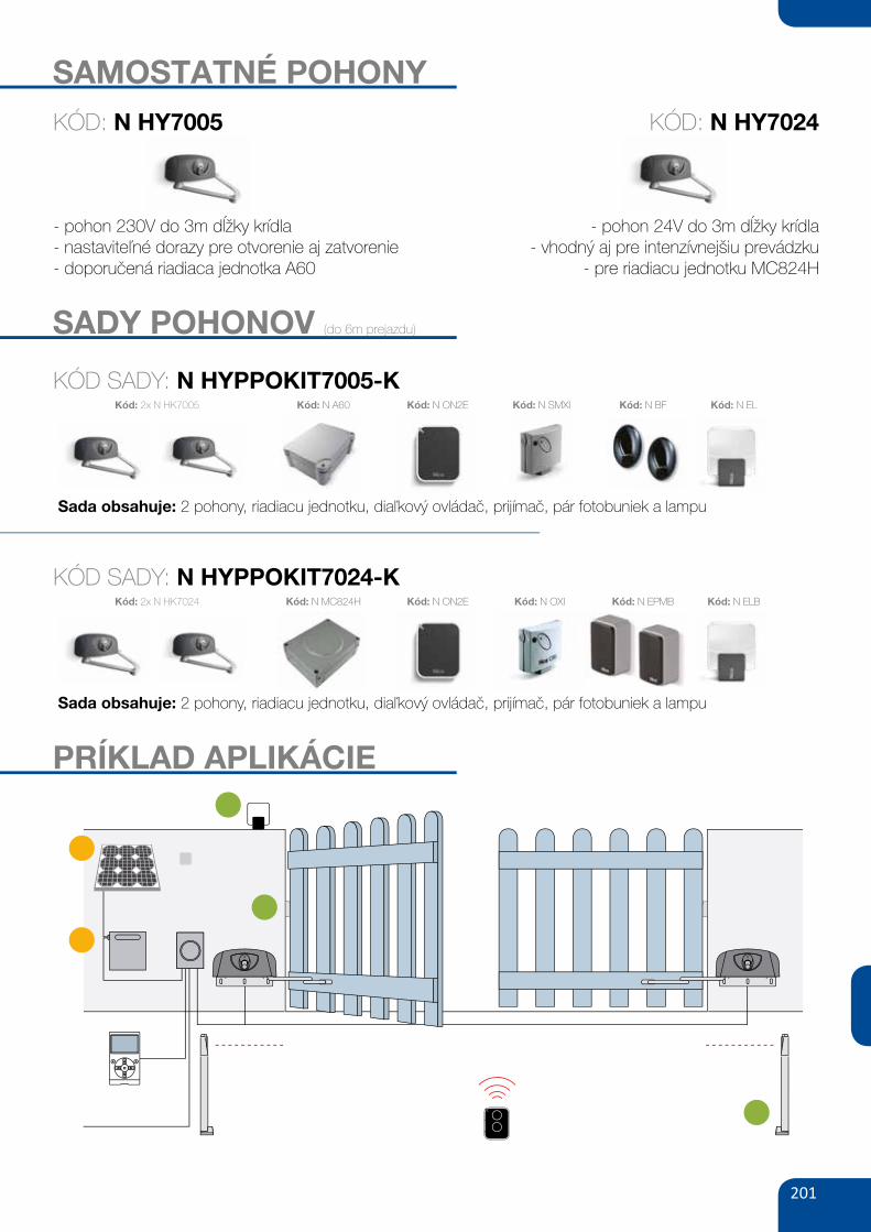
201
SAMOSTATNÉ POHONY
- pohon 230V do 3m dĺžky krídla- nastaviteľné dorazy pre otvorenie aj zatvorenie- doporučená riadiaca jednotka A60
- pohon 24V do 3m dĺžky krídla- vhodný aj pre intenzívnejšiu prevádzku
- pre riadiacu jednotku MC824H
KÓD: N HY7005 KÓD: N HY7024
SADY POHONOV (do 6m prejazdu)
KÓD SADY: N HYPPOKIT7005-K
Sada obsahuje: 2 pohony, riadiacu jednotku, diaľkový ovládač, prijímač, pár fotobuniek a lampu
Kód: 2x N HK7005 Kód: N ON2E Kód: N SMXI Kód: N BF Kód: N ELKód: N A60
KÓD SADY: N HYPPOKIT7024-K
Sada obsahuje: 2 pohony, riadiacu jednotku, diaľkový ovládač, prijímač, pár fotobuniek a lampu
Kód: 2x N HK7024 Kód: N ON2E Kód: N OXI Kód: N EPMB Kód: N ELBKód: N MC824H
PRÍKLAD APLIKÁCIE
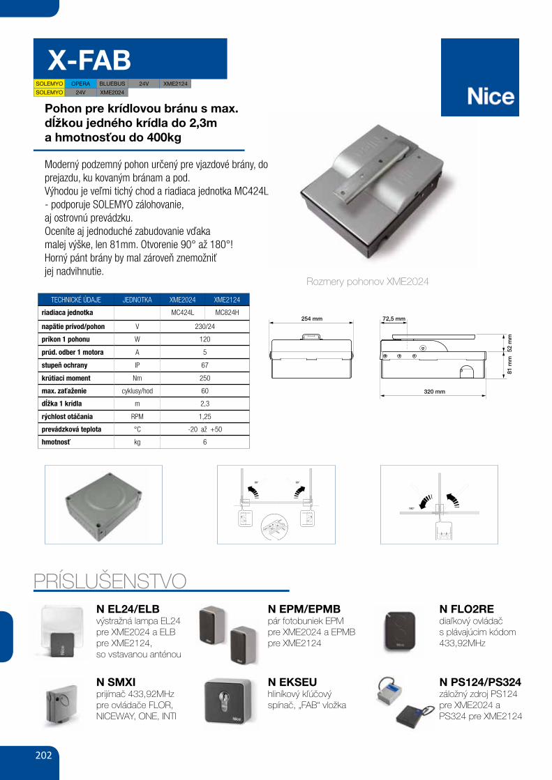
202
X-FAB
Pohon pre krídlovou bránu s max.dĺžkou jedného krídla do 2,3ma hmotnosťou do 400kg
Moderný podzemný pohon určený pre vjazdové brány, do prejazdu, ku kovaným bránam a pod.Výhodou je veľmi tichý chod a riadiaca jednotka MC424L - podporuje SOLEMYO zálohovanie,aj ostrovnú prevádzku.Oceníte aj jednoduché zabudovanie vďakamalej výške, len 81mm. Otvorenie 90° až 180°!Horný pánt brány by mal zároveň znemožniťjej nadvihnutie.
TECHNICKÉ ÚDAJE JEDNOTKA XME2024 XME2124
riadiaca jednotka MC424L MC824H
napätie prívod/pohon V 230/24
príkon 1 pohonu W 120
prúd. odber 1 motora A 5
stupeň ochrany IP 67
krútiaci moment Nm 250
max. zaťaženie cyklusy/hod 60
dĺžka 1 krídla m 2,3
rýchlost otáčania RPM 1,25
prevádzková teplota °C -20 až +50
hmotnosť kg 6
PRÍSLUŠENSTVON EL24/ELBvýstražná lampa EL24 pre XME2024 a ELBpre XME2124,so vstavanou anténou
N SMXIprijímač 433,92MHzpre ovládače FLOR, NICEWAY, ONE, INTI
N EPM/EPMBpár fotobuniek EPM pre XME2024 a EPMBpre XME2124
N FLO2REdiaľkový ovládačs plávajúcim kódom 433,92MHz
N PS124/PS324záložný zdroj PS124 pre XME2024 aPS324 pre XME2124
VIII
254 mm 72,5 mm
320 mm
81m
m52
mm
1
3 4
2
AG G
G
C
D D
E
F
H
C
B
A
ISTXME.4865 Rev00 Xmetro_ok.qxd:Layout 1 25-06-2009 11:45 Pagina VIIIRozmery pohonov XME2024
N EKSEUhliníkový kľúčovýspínač, „FAB“ vložka
X
9
10
90° 90°
180°
ISTXME.4865 Rev00 Xmetro_ok.qxd:Layout 1 25-06-2009 11:45 Pagina X
X
9
10
90° 90°
180°
ISTXME.4865 Rev00 Xmetro_ok.qxd:Layout 1 25-06-2009 11:45 Pagina X
SOLEMYO 24V
SOLEMYO OPERA BLUEBUS 24V
XME2024
XME2124
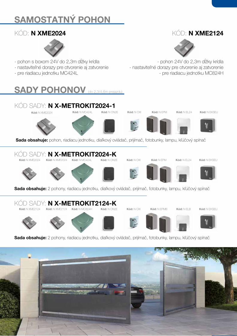
203
SADY POHONOV (do 2,3/4,6m prejazdu)
KÓD SADY: N X-METROKIT2024-1
Sada obsahuje: pohon, riadiacu jednotku, diaľkový ovládač, prijímač, fotobunky, lampu, kľúčový spínač
Kód: N OXI Kód: N EPM Kód: N EL24 Kód: N EKSEU
KÓD SADY: N X-METROKIT2024-K
Sada obsahuje: 2 pohony, riadiacu jednotku, diaľkový ovládač, prijímač, fotobunky, lampu, kľúčový spínač
Kód: N MC424L Kód: N ON2E
Kód: N OXI Kód: N EPM Kód: N EL24 Kód: N EKSEUKód: N MC424L Kód: N ON2E
Kód: N XME2024
Kód: N XME2024Kód: N XME2024
SAMOSTATNÝ POHON
- pohon s boxom 24V do 2,3m dĺžky krídla- nastaviteľné dorazy pre otvorenie aj zatvorenie- pre riadiacu jednotku MC424L
KÓD: N XME2024
- pohon 24V do 2,3m dĺžky krídla- nastaviteľné dorazy pre otvorenie aj zatvorenie
- pre riadiacu jednotku MC824H
KÓD: N XME2124
KÓD SADY: N X-METROKIT2124-K
Sada obsahuje: 2 pohony, riadiacu jednotku, diaľkový ovládač, prijímač, fotobunky, lampu, kľúčový spínač
Kód: N OXI Kód: N EPMB Kód: N ELB Kód: N EKSEUKód: N MC824H Kód: N ON2EKód: N XME2124Kód: N XME2124
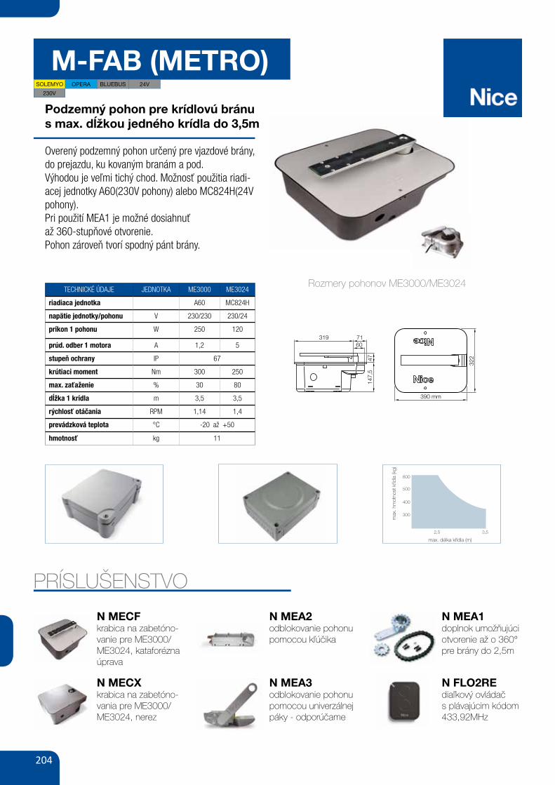
204
M-FAB (METRO)
Podzemný pohon pre krídlovú bránus max. dĺžkou jedného krídla do 3,5m
Overený podzemný pohon určený pre vjazdové brány, do prejazdu, ku kovaným branám a pod.Výhodou je veľmi tichý chod. Možnosť použitia riadi-acej jednotky A60(230V pohony) alebo MC824H(24V pohony).Pri použití MEA1 je možné dosiahnuťaž 360-stupňové otvorenie.Pohon zároveň tvorí spodný pánt brány.
TECHNICKÉ ÚDAJE JEDNOTKA ME3000 ME3024
riadiaca jednotka A60 MC824H
napätie jednotky/pohonu V 230/230 230/24
príkon 1 pohonu W 250 120
prúd. odber 1 motora A 1,2 5
stupeň ochrany IP 67
krútiaci moment Nm 300 250
max. zaťaženie % 30 80
dĺžka 1 krídla m 3,5 3,5
rýchlosť otáčania RPM 1,14 1,4
prevádzková teplota °C -20 až +50
hmotnosť kg 11
PRÍSLUŠENSTVO
N MECFkrabica na zabetóno-vanie pre ME3000/ME3024, kataforézna úprava
N MECXkrabica na zabetóno-vania pre ME3000/ME3024, nerez
N MEA2odblokovanie pohonu pomocou kľúčika
N MEA3odblokovanie pohonu pomocou univerzálnej páky - odporúčame
N MEA1doplnok umožňujúci otvorenie až o 360° pre brány do 2,5m
N FLO2REdiaľkový ovládačs plávajúcim kódom 433,92MHz
410,00
504,30 brutto
MEA1akcesoria zwiększające kąt
otwarcia do 1800
PLA 10
MEA2 MEA3 BF MEA5
PLA 11zamek elektromagnetyczny pionowy
mechanizm odblokowania
awaryjnego przy pomocy klucza
mechanizm odblokowania
awaryjnego przy pomocy dźwigni
odporny na zanieczyszczenia
fotokomórka (para)
zasięg 15-30m
dźwignia odblokowująca
do MEA3 (dodatkowa)
zamek elektromagnetyczny poziomy
340,00
418,20 brutto
220,00
270,60 brutto
220,00
270,60 brutto
160,00
196,80 brutto
64,00
78,72 brutto
340,00
418,20 brutto
SOLEMYO (SYKCE)
1 350,00
1 660,50 brutto
zestaw zasilania słonecznego
WYMIARYWYMIARY
M-FAB
AKCESORIA
SCHEMAT INSTALACJI PARAMETRY SKRZYDŁA BRAMY
max. (m)délka křídla
max.
(kg)
hm
otn
ost kř
ídla
[legenda]2,5 3,5
600
500
400
300
147,
547
7131960
322
390 mm
M-FAB
ERA FLOR
M-FAB
SMILO
zestaw do bram dwuskrzydłowych: 2 siłowniki samohamowne ME3000 do bram o długości do 3.0 m, 2 obudowy podziemne MECF z zamkami MEA3,
centrala sterująca A60, radioodbiornik SMXI, 1 pilot dwukanałowy FLO2RE, fotokomórki BFzestaw do bram dwuskrzydłowych: 2 siłowniki samohamowne ME3000 do bram o długości do 3.0 m, 2 obudowy podziemne MECF z zamkami MEA3,
centrala sterująca A60, radioodbiornik SMXIS, 2 piloty dwukanałowe SM2, fotokomórki BF
PRZYKŁADOWY ZESTAW DO UŻYTKU PRZYDOMOWEGO
5 621,10
5 645,70
4 570,00
4 590,00
|65AUTOMATYKA DO BRAM SKRZYDŁOWYCH
cena netto cena brutto
POZOSTAŁE AKCESORIA STR. 96-105
PS324akumulator 24V 2.2 Ah z wbudowaną
kartą ładowania do centrali MC824H360,00
442,80 brutto
66 GATE&DOOR 2013
m-FAb
600
500
400
300
2,5 3
147,
547
7131960
322
390 mm
230V24VbLuEbusOPERAsOLEmyO
mE3024 mE3000 mE3000L
- 23024 -5 1.2 1.3
120 250 300
1.4 1.14 0.8250 300 25076 30 20
67-20 ÷ +50
390x322x194.5 h11
CODE DESCRIPTION PACK/PALLET
mE3024 IRREVERSIBLE, 24 Vdc, WITH MAGNETIC ENCODER, COMPLETE WITH CONNECTING LEVER AND MECHANICAL STOP FOR THE CLOSING MANOEUVRE
18
mE3000 IRREVERSIBLE, 230 Vac, HIGH SPEED, GREASE LUBRICATION, COMPLETE WITH CONNECTING LEVER AND MECHANICAL STOP FOR THE CLOSING MANOEUVRE
18
mE3000L IRREVERSIBLE, 230 Vac, LOW SPEED, GREASE LUBRICATION, COMPLETE WITH CONNECTING LEVER AND MECHANICAL STOP FOR THE CLOSING MANOEUVRE
18
CODE DESCRIPTION PACK/PALLET
mECx ExTERNALLY CHAMFERED FOUNDATION BOx IN STAINLESS STEEL WITH MECHANICAL STOP ON OPENING
20
mECF ExTERNALLY CHAMFERED FOUNDATION BOx WITH CATAPHORESIS FINISH WITH MECHANICAL STOP ON OPENING
20
NOTE: key release mechanism, freely compatible with selection of models MEA2 and MEA3 motor.
mAx
. GAT
E W
EIGh
T (k
G)
mAx. GATE LENGTh (m)The shape, the height of the gate and the weather conditions can considerably reduce the values shown in the graph to the side. Use in windy areas 230 Vac models.
For swing gates with leaves up to 3 m, underground installation. Irreversible electromechanical gear motor, also available in 24 Vdc versions with magnetic encoder.
An even more evolved range: 3 types of electromechanical gear motors irreversible m-Fab.
2 foundation boxes externally chamfered, Fab box, with mechanical stop on opening: • in stainless steel (MECX), ideal for use in extreme conditions, • with the cataphoresis paint finish (MECF), highly resistant to corrosion.
Reliable and resistant: motors made up of solid internal parts in metal. New IP67 waterproof die cast aluminium.
Total freedom of choice: release from inside and outside, two key-operated models or freely compatible lever version and easily activated with just one hand.
simple to use: mechanical stop system on closure. Standard opening max. 110°, optional opening 360°.
Totally compatible with the previous Metro series.
Recommended control units: Mindy A6F, A60, A700F; for ME3024 Moonclever MC824H.
24 Vdc version with magnetic encoder. Perfect for intensive use, compatible with the control unit Moonclever MC824H:
• simple programming, by means of a single key; • self-learning of opening and closing limit positions; • automatic fault diagnostics; • programming of pause time; • pedestrian pass door; • deceleration on opening and closing; • obstacle detection with dual technology; • operation in event of power failure by means of optional rechargeable batteries (PS324); • provision for connection of latest generation resistive sensitive edges.
TEChNICAL sPECIFICATIONsCODEELECTRICAL DATAPOWER SUPPLY (Vac 50 Hz)*POWER SUPPLY (Vdc)ABSORPTION (A)POWER (W)PERFORmANCE DATASPEED (rpm)TORqUE (Nm)WORK CYCLE (CYCLES/HOUR)DImENsIONAL AND GENERAL DATAPROTECTION LEVEL (IP)WORKING TEMP. (°C MIN/MAx)DIMENSIONS (mm)WEIGHT (kg)
*60 Hz version available on request.
MORE RELIABILITY AND RESISTANCE
WATERPROOF, WITH IP67 PROTECTION RATING
ExTERNALLY CHAMFERED FAB BOx
DImENsIONsuTILIsATION LImITs
Rozmery pohonov ME3000/ME3024
66 GATE&DOOR 2013
m-FAb
600
500
400
300
2,5 3
147,
547
7131960
322
390 mm
230V24VbLuEbusOPERAsOLEmyO
mE3024 mE3000 mE3000L
- 23024 -5 1.2 1.3
120 250 300
1.4 1.14 0.8250 300 25076 30 20
67-20 ÷ +50
390x322x194.5 h11
CODE DESCRIPTION PACK/PALLET
mE3024 IRREVERSIBLE, 24 Vdc, WITH MAGNETIC ENCODER, COMPLETE WITH CONNECTING LEVER AND MECHANICAL STOP FOR THE CLOSING MANOEUVRE
18
mE3000 IRREVERSIBLE, 230 Vac, HIGH SPEED, GREASE LUBRICATION, COMPLETE WITH CONNECTING LEVER AND MECHANICAL STOP FOR THE CLOSING MANOEUVRE
18
mE3000L IRREVERSIBLE, 230 Vac, LOW SPEED, GREASE LUBRICATION, COMPLETE WITH CONNECTING LEVER AND MECHANICAL STOP FOR THE CLOSING MANOEUVRE
18
CODE DESCRIPTION PACK/PALLET
mECx ExTERNALLY CHAMFERED FOUNDATION BOx IN STAINLESS STEEL WITH MECHANICAL STOP ON OPENING
20
mECF ExTERNALLY CHAMFERED FOUNDATION BOx WITH CATAPHORESIS FINISH WITH MECHANICAL STOP ON OPENING
20
NOTE: key release mechanism, freely compatible with selection of models MEA2 and MEA3 motor.
mAx
. GAT
E W
EIGh
T (k
G)
mAx. GATE LENGTh (m)The shape, the height of the gate and the weather conditions can considerably reduce the values shown in the graph to the side. Use in windy areas 230 Vac models.
For swing gates with leaves up to 3 m, underground installation. Irreversible electromechanical gear motor, also available in 24 Vdc versions with magnetic encoder.
An even more evolved range: 3 types of electromechanical gear motors irreversible m-Fab.
2 foundation boxes externally chamfered, Fab box, with mechanical stop on opening: • in stainless steel (MECX), ideal for use in extreme conditions, • with the cataphoresis paint finish (MECF), highly resistant to corrosion.
Reliable and resistant: motors made up of solid internal parts in metal. New IP67 waterproof die cast aluminium.
Total freedom of choice: release from inside and outside, two key-operated models or freely compatible lever version and easily activated with just one hand.
simple to use: mechanical stop system on closure. Standard opening max. 110°, optional opening 360°.
Totally compatible with the previous Metro series.
Recommended control units: Mindy A6F, A60, A700F; for ME3024 Moonclever MC824H.
24 Vdc version with magnetic encoder. Perfect for intensive use, compatible with the control unit Moonclever MC824H:
• simple programming, by means of a single key; • self-learning of opening and closing limit positions; • automatic fault diagnostics; • programming of pause time; • pedestrian pass door; • deceleration on opening and closing; • obstacle detection with dual technology; • operation in event of power failure by means of optional rechargeable batteries (PS324); • provision for connection of latest generation resistive sensitive edges.
TEChNICAL sPECIFICATIONsCODEELECTRICAL DATAPOWER SUPPLY (Vac 50 Hz)*POWER SUPPLY (Vdc)ABSORPTION (A)POWER (W)PERFORmANCE DATASPEED (rpm)TORqUE (Nm)WORK CYCLE (CYCLES/HOUR)DImENsIONAL AND GENERAL DATAPROTECTION LEVEL (IP)WORKING TEMP. (°C MIN/MAx)DIMENSIONS (mm)WEIGHT (kg)
*60 Hz version available on request.
MORE RELIABILITY AND RESISTANCE
WATERPROOF, WITH IP67 PROTECTION RATING
ExTERNALLY CHAMFERED FAB BOx
DImENsIONsuTILIsATION LImITs
SOLEMYO OPERA BLUEBUS 24V
230V
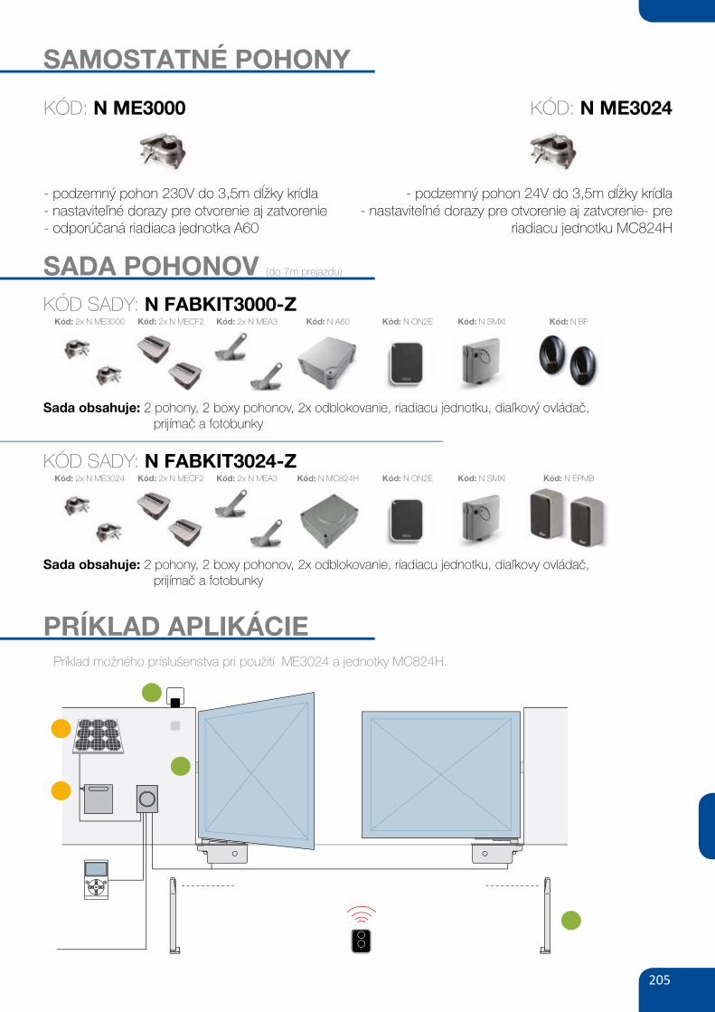
205
SAMOSTATNÉ POHONY
- podzemný pohon 230V do 3,5m dĺžky krídla- nastaviteľné dorazy pre otvorenie aj zatvorenie- odporúčaná riadiaca jednotka A60
- podzemný pohon 24V do 3,5m dĺžky krídla- nastaviteľné dorazy pre otvorenie aj zatvorenie- pre
riadiacu jednotku MC824H
SADA POHONOV (do 7m prejazdu)
KÓD: N ME3000 KÓD: N ME3024
Príklad možného príslušenstva pri použití ME3024 a jednotky MC824H.
KÓD SADY: N FABKIT3000-Z
Sada obsahuje: 2 pohony, 2 boxy pohonov, 2x odblokovanie, riadiacu jednotku, diaľkový ovládač, prijímač a fotobunky
Kód: N SMXI Kód: N BFKód: 2x N MEA3 Kód: N ON2EKód: 2x N MECF2Kód: 2x N ME3000 Kód: N A60
PRÍKLAD APLIKÁCIE
KÓD SADY: N FABKIT3024-Z
Sada obsahuje: 2 pohony, 2 boxy pohonov, 2x odblokovanie, riadiacu jednotku, diaľkovy ovládač, prijímač a fotobunky
Kód: N SMXI Kód: N EPMBKód: 2x N MEA3 Kód: N ON2EKód: 2x N MECF2Kód: 2x N ME3024 Kód: N MC824H
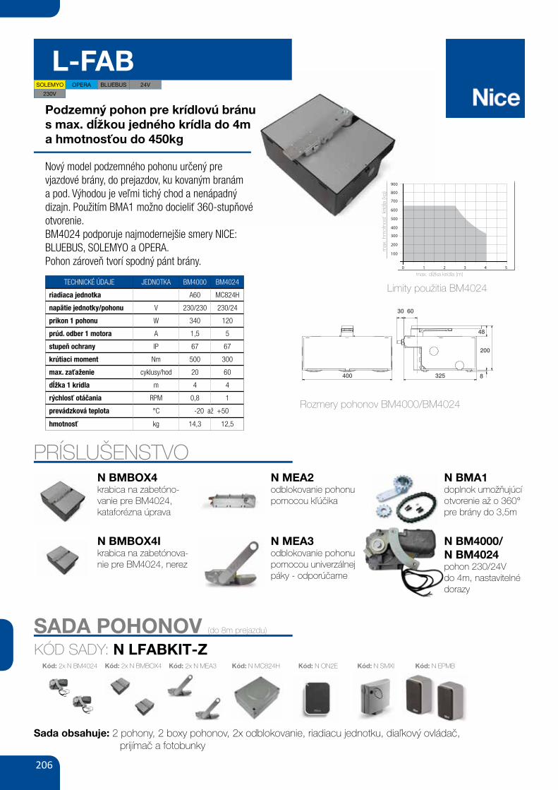
206
L-FAB
Podzemný pohon pre krídlovú bránus max. dĺžkou jedného krídla do 4ma hmotnosťou do 450kg
Nový model podzemného pohonu určený pre vjazdové brány, do prejazdov, ku kovaným branám a pod. Výhodou je veľmi tichý chod a nenápadný dizajn. Použitím BMA1 možno docieliť 360-stupňové otvorenie.BM4024 podporuje najmodernejšie smery NICE: BLUEBUS, SOLEMYO a OPERA.Pohon zároveň tvorí spodný pánt brány.
TECHNICKÉ ÚDAJE JEDNOTKA BM4000 BM4024
riadiaca jednotka A60 MC824H
napätie jednotky/pohonu V 230/230 230/24
príkon 1 pohonu W 340 120
prúd. odber 1 motora A 1,5 5
stupeň ochrany IP 67 67
krútiaci moment Nm 500 300
max. zaťaženie cyklusy/hod 20 60
dĺžka 1 krídla m 4 4
rýchlosť otáčania RPM 0,8 1
prevádzková teplota °C -20 až +50
hmotnosť kg 14,3 12,5
PRÍSLUŠENSTVON BMBOX4krabica na zabetóno-vanie pre BM4024, kataforézna úprava
N BMBOX4Ikrabica na zabetónova-nie pre BM4024, nerez
N MEA2odblokovanie pohonu pomocou kľúčika
N MEA3odblokovanie pohonu pomocou univerzálnej páky - odporúčame
N BMA1doplnok umožňujúcí otvorenie až o 360°pre brány do 3,5m
N BM4000/N BM4024pohon 230/24Vdo 4m, nastavitelnédorazy
SOLEMYO OPERA BLUEBUS 24V
SADA POHONOV (do 8m prejazdu)
KÓD SADY: N LFABKIT-Z
Sada obsahuje: 2 pohony, 2 boxy pohonov, 2x odblokovanie, riadiacu jednotku, diaľkový ovládač, prijímač a fotobunky
Kód: N SMXI Kód: N EPMBKód: 2x N MEA3 Kód: N ON2EKód: 2x N BMBOX4Kód: 2x N BM4024 Kód: N MC824H
230V
Rozmery pohonov BM4000/BM4024
EN
English – 1
ENGLISH
Recommendations regarding safety• ATTENTION! – This manual contains important instructions and recom-
mendations regarding the safety of persons. Incorrect installation cancause serious injury. Read the manual completely before starting work. If indoubt, suspend the installation and request clarifications from the Nice After-sales Assistance.
• ATTENTION! – Important instructions: keep this manual for any futuremaintenance interventions and product disposal.
• ATTENTION! – In compliance with the most recent European Legisla-tion, the realisation of an automatic door or gate must respect the Stan-dards envisioned by the 2006/42/CE Directive (ex 98/37/CE) (MachineryDirective) and in particular, the EN 12445; EN 12453; EN 12635 and EN13241-1 Standards, which allow to declare conformity of the automa-tion. Considering this, all product installation, connection, inspectionand maintenance operations must only be performed by a qualified andskilled technician!
Recommendations for installation• Before starting installation, check whether this product is suitable to auto-
mate your gate or door (see chapter 3 and the “Product technical features”).If it is not suitable, DO NOT proceed with installation.
• All installation and maintenance operations must take place with theautomation disconnected from the electric power input. If the powerinput disconnection device is not visible from the place where the automationis positioned, before starting work, affix a sign onto the disconnection devicethat states "ATTENTION! MAINTENANCE IN PROGRESS”.
• Handle the automation with care during installation, preventing crushing, blows,falls or contact with liquids of any nature. Do not place the product near to heatsources or expose it to naked flames. All of these actions can damage it and because of malfunctioning or dangerous situations. If this occurs, suspend installa-tion immediately and contact the Nice After-sales Assistance.
• Do not modify any product parts. Unauthorised operations can only causemalfunctioning. The manufacturer declines liability for damage deriving fromarbitrary modifications to the product.
• If the gate or door to be automated has a pedestrian door the plant must beset up with a control system that prevents functioning of the motor when thepedestrian door is open.
• The product packaging material must be disposed of in compliance withlocal legislation.
GENERAL SAFETY WARNINGSAND PRECAUTIONS1
This product is destined to be used to automate gates or doors with hingedpanels.ATTENTION! – Any use different to that described and in environmentalconditions different to those stated in this manual must be consideredimproper and prohibited!
The product is an electro-mechanical gear motor, with a 24 Vdc motor. The gearmotor is powered by the external control unit, to which it must be connected.If the electric energy is interrupted (black-out), the gate panels can be movedby releasing the gear motor using the relevant wrench; to perform the manualmanoeuvre, see chapter 8.
The product is available in the version- BM5024 with encoder, suitable for MC824H control units.
Do not use gear motors with incompatible control units.
DESCRIPTION OF THE PRODUCTAND DESTINATION OF USE2
3.1 - Preliminary checks on installationBefore performing installation, check the integrity of the product components,the adequacy of the model chosen and the suitability of the environment des-tined for installation.
IMPORTANT – The gear motor cannot automate a manual gate thatdoes not have an efficient and safe mechanical structure. Moreover, itcannot solve defects caused by incorrect installation or bad mainte-nance of the gate itself.
3.2 - Suitability of the gate to automate and the surroundingenvironment
• Check that the gate mechanical structure is suitable to be automated andcomplies with the Standards in force on the territory (if necessary, refer to thedata given on the gate label).
• Moving the gate panel manually in Opening and in Closure, check that themovement takes place with the same and constant friction in all points of therun (there must not be moments of greater effort).
• Check that the gate panel stays in equilibrium, i.e. that is does not move iftaken manually into any position and left.
• Check that the space around the gear motor allows to manually release thegate panels easily and safely.
• Envision end run retainers on the ground both for opening and closure ofthe gate.
• Check that the gear motor fixing area is compatible with the clearance of thelatter (fig. 1).
3.3 - Limits of use for the productBefore installing the product, check that the gate panel has dimensions andweight that lie within the limits given in graph 1; also evaluate the climatic con-ditions (e.g. strong wind) present in the place of installation. They can greatlyreduce the values given in the graph.
INSTALLATION3
3.4 - Set-up for installationFig. 2 shows an example of automated plant realised with Nice components.These components are positioned according to the typical and usual layout.With reference to fig. 2, establish the approximate position where each com-ponent envisioned in the plant will be installed and the most appropriate con-nection layout.
GRAPH 1
100
1 2 3 4 5
200
300
400
500
600
700
900
800
PAN
EL
MA
X W
EIG
HT
(Kg
)
PANEL MAX LENGTH (m)
130 60
48
8
200
325400
58 GATE&DOOR 2013
≥ 130
≥ 300
B ≥ 710 mmA ≥ 450
B ≤
450
A ≤
350
hyPPO 7000
800
700
600
500
400
300
2002 2,5 3
HY7005
HY7005 / HY7024
165350 mm
242
9015
2
230V24VbLuEbusOPERAsOLEmyO
hy7024 hy7005
- 23024 -5 1.2
120 250
2 1.7250 40080 30
43-20 ÷ +50
350x165x242 h13
For swing gates with leaves up to 3 m, also ideal for large pillars. Electromechanical gear motor, surface mounted, also in 24 Vdc version with magnetic encoder, with articulated arm.
Single model for right and left leaves. Two irreversible versions, with 230 Vac (HY7005) and 24 Vdc (HY7024) power supplies with magnetic encoder.
Fewer connections mean quicker installation.
Pre-wired, incorporated double limit-switch both during opening and closing (HY7005).
mAx
. GAT
E W
EIGh
T (k
G)
mAx. GATE LENGTh (m)
N.B. The above values are valid if the motor is used with standard accessories. The shape, the height of the gate and the weather conditions can considerably reduce the values shown in the graph to the side. Use in windy areas 230 Vac models.
CODE DESCRIPTION PACK/PALLET
hy7024 IRREVERSIBLE, 24 Vdc, WITH MAGNETIC ENCODER, WITH SHEAR-PROOF ARTICULATED ARM, GALVANIZED AND PAINTED
16
hy7005 IRREVERSIBLE, 230 Vac, WITH STURDY ARTICULATED SHEAR-PROOF ARM, GALVANIZED AND PAINTED, WITH LIMIT SWITCH ON OPENING AND CLOSING
16
Easy and quick to install: thanks to fewer connections and nothing welded to the gates.
Long-lasting: solid metal mechanics.
Compact: shockproof bodywork with no sharp corners.
Recommended control units: Mindy A6F, A60, A700F; for HY7024 Moonclever MC824H.
24 Vdc version with magnetic encoder. Perfect for intensive use, compatible with the control unit Moonclever MC824H: • simple programming, by means of a single key; • self-learning of opening and closing limit positions; • automatic fault diagnostics; • programming of pause time; • pedestrian pass door; • deceleration on opening and closing; • obstacle detection with dual technology; • operation in event of power failure by means of optional rechargeable batteries (PS324); • provision for connection of latest generation resistive sensitive edges.
TEChNICAL sPECIFICATIONsCODEELECTRICAL DATAPOWER SUPPLY (Vac 50 Hz)*POWER SUPPLY (Vdc)ABSORPTION (A)POWER (W)PERFORmANCE DATASPEED (rpm)TORqUE (Nm)WORK CYCLE (%)DImENsIONAL AND GENERAL DATAPROTECTION LEVEL (IP)WORKING TEMP. (°C MIN/MAx)DIMENSIONS (mm)WEIGHT (kg)
*60 Hz version available on request.
A Standard armb Arm with accessory HYA12
uTILIsATION LImITs DImENsIONs
STURDY, ANTI-SHEARING ARM, GALVANISED AND PAINTED; STRENGTHENED IN THOSE AREAS SUBjECTED TO GREATER MECHANICAL STRESS
DIE-CAST, ALUMINIUM, KEY-OPERATED UNLOCK SYSTEM, COMPLETE WITH PROTECTED KEY. DESIGNED TO ACCOMMODATE ExTERNAL RELEASE, TOO
PL 3.3 - Ograniczenia związane zużyciem produktu
Przed zamontowaniem produktu należy sprawdzić, czywymiary i ciężar skrzydła bramki znajdują się w zakresiegranic wskazanych na wykresie 1 ; należy oszacowaćrównież warunki klimatyczne (np. silny wiatr) w miejscumontażu: które mogą znacznie ograniczyć wartościwskazane na wykresie.
NL 3.3 - Gebruikslimieten van het pro-duct
Alvorens het product te installeren, moet gecontroleerdworden of de vleugel van het hek de afmetingen en hetgewicht heeft die zich binnen de limieten van grafiek1 bevinden. Beoordeel ook de klimaatsomstandighe-den (bijvoorbeeld sterke wind) in de plaats van installa-tie: deze kunnen de waarden in de grafiek aanzienlijkverlagen.
EN 5 - Electrical ConnectionsFor BM4000, connect the cables as follows:
Black = “open” phaseBrown = “close” phaseGrey = CommonYellow/Green =
IT 5 - Collegamenti elettriciPer il BM4000, collegare i cavi nel modo seguente:
Nero = Fase “apre”Marrone = Fase “chiude”Grigio = ComuneGiallo/Verde =
FR 5 - Branchements électriquesPour le modèle BM4000, brancher les câblescomme suit :
Noir = phase « ouverture »
0004MB4204MBType Electro-mechanical dear motors for gates and doors with hinged panelsPower input 24 V 230 V Peak absorption A 5,1A 5Maximum absorption A 1A 5,1Peak Power W 043W 021Maximum power W 081W 63Capacitor incorporated Fμ7–Protection rating IP 67Run from 0° to 110° or 360°Idle speed mpr 58,0)*mpr 52,1( mpr 1Speed at nominal torque mpr 56,0mpr 58,0Maximum torque mN 005mN 003Nominal torque mN 521mN 57Functioning temperature from -20°C to +50°CCycles/hour at the nominal torque 0206Dimensions 375 mm x 225 mm x h 110 mm Weight gK 3,41gK 5,21
* Value refers to a power supply voltage of 30V.
RECOMMENDATIONS: • All technical features stated make reference at a room temperature of 20°C (± 5°C). • Nice S.p.a. reserves the right to modify the product at any time itdeems necessary, however maintaining the same functionality and destination of use.
EN - PRODUCT TECHNICAL FEATURES
100
10 2 3 4 5
200
300
400
500
600
700
900
800
EN 3.3 - Limits of use for the productBefore installing the product, check that the gate panelhas dimensions and weight that lie within the limits giv-en in graph 1 ; also evaluate the climatic conditions(e.g. strong wind) present in the place of installation:they can greatly reduce the values given in the graph.
IT 3.3 - Limiti d’impiego del prodottoPrima di eseguire l’installazione del prodotto, verificareche l’anta del cancello abbia dimensioni e peso rien-tranti nei limiti riportati nel grafico 1 ; valutare anche lecondizioni climatiche (es. vento forte) presenti nel luogod’installazione: queste possono ridurre notevolmente ivalori riportati nel graco.
FR 3.3 - Limites d’utilisation du produitAvant d’installer le produit, vérifier que le vantail du por-tail présente des dimensions et un poids compris dansles limites reprises au graphique 1 ; évaluer aussi lesconditions climatiques (ex. vent fort) existantes dans lelieu d’installation: elles peuvent réduire considérable-ment les valeurs reprises sur le graphique.
ES 3.3 - Límites de uso del productoAntes de instalar el producto, controle que las dimen-siones y el peso de la hoja de la cancela estén dentrode los límites que se muestran en el gráfico 1 ; evalúetambién las condiciones climáticas (ej. viento fuerte)presentes en el lugar de la instalación: ya que puedenreducir considerablemente los valores mostrados en elgráfico.
DE 3.3 - Einsatzgrenzen des ProduktsVor der Installation des Produkts ist zu prüfen, obAbmessungen und Gewicht des Torflügels innerhalbder in Diagramm 1 ; angegebenen Grenzen liegen; zuberücksichtigen sind auch die klimatischen Bedingun-gen (z. B. starker Wind), die am Installationsort vorherr-schen und die im Diagramm angegebenen Werte deut-lich verringern können.
EN - Panel max weight (Kg)IT - Peso massimo dell’anta (Kg)FR - Poids max du vantail (Kg)ES - Peso máx. de la hoja (Kg)DE - Max. Flügelgewichtl (Kg)PL - Max ciężar skrzydła (Kg)NL - Max gewicht vleugel (Kg)
• EN - GRAPH 1 • IT - GRAFICO 1 • FR - GRAPHIQUE 1• ES - GRÁFICO 1 • DE - DIAGRAMM 1 • PL - WYKRES1 • NL - GRAFIEK 1
EN - Panel max length (m)IT - Lunghezza massima dell’anta (m)FR - Longueur max du vantail (m)ES - Longitud máx. de la hoja (m)DE - Max. Flügellänge (m)PL - Max długość skrzydła (m)NL - Max lengte vleugel (m)
Marron = phase « fermeture »Gris = communJaune/Vert =
ES 5 - Conexiones eléctricasPara el BM4000 conecte los cables de la siguientemanera:
Negro = Fase “abrir”Marrón = Fase “cerrar”Gris = ComúnAmarillo/Verde =
DE 5 - Elektrische AnschüsseFür BM4000, die Kabel wie folgt anschließen:
Schwarz = Phase “ö¡net”Braun = Phase “schließt”Grau = GemeinsamGelb/Grün =
PL 5 - Połączenia elektryczneDla BM4000, podłącz przewody w następującysposób:
Czarny = Faza “otwiera”Brązowy = Faza “zamyka”Szary = WspólnyŻółto/zielony =
NL 5 - Elektrische aansluitingenSluit voor de BM4000 de kabels als volgt aan:
Zwart = Fase “open”Bruin = Fase “sluit”Grijs = GemeenschappelijkGroengeel =
Limity použitia BM4024
58 GATE&DOOR 2013
≥ 130
≥ 300
B ≥ 710 mmA ≥ 450
B ≤
450
A ≤
350
hyPPO 7000
800
700
600
500
400
300
2002 2,5 3
HY7005
HY7005 / HY7024
165350 mm
242
9015
2
230V24VbLuEbusOPERAsOLEmyO
hy7024 hy7005
- 23024 -5 1.2
120 250
2 1.7250 40080 30
43-20 ÷ +50
350x165x242 h13
For swing gates with leaves up to 3 m, also ideal for large pillars. Electromechanical gear motor, surface mounted, also in 24 Vdc version with magnetic encoder, with articulated arm.
Single model for right and left leaves. Two irreversible versions, with 230 Vac (HY7005) and 24 Vdc (HY7024) power supplies with magnetic encoder.
Fewer connections mean quicker installation.
Pre-wired, incorporated double limit-switch both during opening and closing (HY7005).
mAx
. GAT
E W
EIGh
T (k
G)
mAx. GATE LENGTh (m)
N.B. The above values are valid if the motor is used with standard accessories. The shape, the height of the gate and the weather conditions can considerably reduce the values shown in the graph to the side. Use in windy areas 230 Vac models.
CODE DESCRIPTION PACK/PALLET
hy7024 IRREVERSIBLE, 24 Vdc, WITH MAGNETIC ENCODER, WITH SHEAR-PROOF ARTICULATED ARM, GALVANIZED AND PAINTED
16
hy7005 IRREVERSIBLE, 230 Vac, WITH STURDY ARTICULATED SHEAR-PROOF ARM, GALVANIZED AND PAINTED, WITH LIMIT SWITCH ON OPENING AND CLOSING
16
Easy and quick to install: thanks to fewer connections and nothing welded to the gates.
Long-lasting: solid metal mechanics.
Compact: shockproof bodywork with no sharp corners.
Recommended control units: Mindy A6F, A60, A700F; for HY7024 Moonclever MC824H.
24 Vdc version with magnetic encoder. Perfect for intensive use, compatible with the control unit Moonclever MC824H: • simple programming, by means of a single key; • self-learning of opening and closing limit positions; • automatic fault diagnostics; • programming of pause time; • pedestrian pass door; • deceleration on opening and closing; • obstacle detection with dual technology; • operation in event of power failure by means of optional rechargeable batteries (PS324); • provision for connection of latest generation resistive sensitive edges.
TEChNICAL sPECIFICATIONsCODEELECTRICAL DATAPOWER SUPPLY (Vac 50 Hz)*POWER SUPPLY (Vdc)ABSORPTION (A)POWER (W)PERFORmANCE DATASPEED (rpm)TORqUE (Nm)WORK CYCLE (%)DImENsIONAL AND GENERAL DATAPROTECTION LEVEL (IP)WORKING TEMP. (°C MIN/MAx)DIMENSIONS (mm)WEIGHT (kg)
*60 Hz version available on request.
A Standard armb Arm with accessory HYA12
uTILIsATION LImITs DImENsIONs
STURDY, ANTI-SHEARING ARM, GALVANISED AND PAINTED; STRENGTHENED IN THOSE AREAS SUBjECTED TO GREATER MECHANICAL STRESS
DIE-CAST, ALUMINIUM, KEY-OPERATED UNLOCK SYSTEM, COMPLETE WITH PROTECTED KEY. DESIGNED TO ACCOMMODATE ExTERNAL RELEASE, TOO
max. dĺžka krídla (m)
max
. hm
otno
sť k
rídla
(kg)
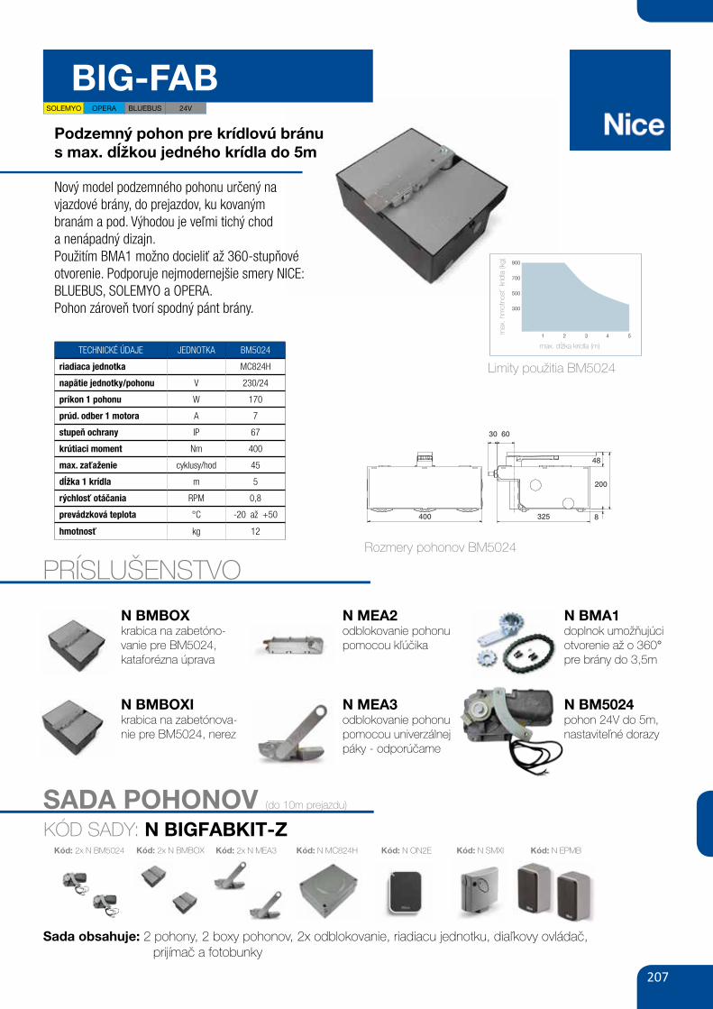
207
SADA POHONOV (do 10m prejazdu)
KÓD SADY: N BIGFABKIT-Z
Sada obsahuje: 2 pohony, 2 boxy pohonov, 2x odblokovanie, riadiacu jednotku, diaľkovy ovládač, prijímač a fotobunky
Kód: N SMXI Kód: N EPMBKód: 2x N MEA3 Kód: N ON2EKód: 2x N BMBOXKód: 2x N BM5024 Kód: N MC824H
BIG-FABPodzemný pohon pre krídlovú bránus max. dĺžkou jedného krídla do 5m
Nový model podzemného pohonu určený navjazdové brány, do prejazdov, ku kovanýmbranám a pod. Výhodou je veľmi tichý choda nenápadný dizajn.Použitím BMA1 možno docieliť až 360-stupňovéotvorenie. Podporuje nejmodernejšie smery NICE:BLUEBUS, SOLEMYO a OPERA.Pohon zároveň tvorí spodný pánt brány.
TECHNICKÉ ÚDAJE JEDNOTKA BM5024
riadiaca jednotka MC824H
napätie jednotky/pohonu V 230/24
príkon 1 pohonu W 170
prúd. odber 1 motora A 7
stupeň ochrany IP 67
krútiaci moment Nm 400
max. zaťaženie cyklusy/hod 45
dĺžka 1 krídla m 5
rýchlosť otáčania RPM 0,8
prevádzková teplota °C -20 až +50
hmotnosť kg 12
PRÍSLUŠENSTVO
EN
English – 1
ENGLISH
Recommendations regarding safety• ATTENTION! – This manual contains important instructions and recom-
mendations regarding the safety of persons. Incorrect installation cancause serious injury. Read the manual completely before starting work. If indoubt, suspend the installation and request clarifications from the Nice After-sales Assistance.
• ATTENTION! – Important instructions: keep this manual for any futuremaintenance interventions and product disposal.
• ATTENTION! – In compliance with the most recent European Legisla-tion, the realisation of an automatic door or gate must respect the Stan-dards envisioned by the 2006/42/CE Directive (ex 98/37/CE) (MachineryDirective) and in particular, the EN 12445; EN 12453; EN 12635 and EN13241-1 Standards, which allow to declare conformity of the automa-tion. Considering this, all product installation, connection, inspectionand maintenance operations must only be performed by a qualified andskilled technician!
Recommendations for installation• Before starting installation, check whether this product is suitable to auto-
mate your gate or door (see chapter 3 and the “Product technical features”).If it is not suitable, DO NOT proceed with installation.
• All installation and maintenance operations must take place with theautomation disconnected from the electric power input. If the powerinput disconnection device is not visible from the place where the automationis positioned, before starting work, affix a sign onto the disconnection devicethat states "ATTENTION! MAINTENANCE IN PROGRESS”.
• Handle the automation with care during installation, preventing crushing, blows,falls or contact with liquids of any nature. Do not place the product near to heatsources or expose it to naked flames. All of these actions can damage it and because of malfunctioning or dangerous situations. If this occurs, suspend installa-tion immediately and contact the Nice After-sales Assistance.
• Do not modify any product parts. Unauthorised operations can only causemalfunctioning. The manufacturer declines liability for damage deriving fromarbitrary modifications to the product.
• If the gate or door to be automated has a pedestrian door the plant must beset up with a control system that prevents functioning of the motor when thepedestrian door is open.
• The product packaging material must be disposed of in compliance withlocal legislation.
GENERAL SAFETY WARNINGSAND PRECAUTIONS1
This product is destined to be used to automate gates or doors with hingedpanels.ATTENTION! – Any use different to that described and in environmentalconditions different to those stated in this manual must be consideredimproper and prohibited!
The product is an electro-mechanical gear motor, with a 24 Vdc motor. The gearmotor is powered by the external control unit, to which it must be connected.If the electric energy is interrupted (black-out), the gate panels can be movedby releasing the gear motor using the relevant wrench; to perform the manualmanoeuvre, see chapter 8.
The product is available in the version- BM5024 with encoder, suitable for MC824H control units.
Do not use gear motors with incompatible control units.
DESCRIPTION OF THE PRODUCTAND DESTINATION OF USE2
3.1 - Preliminary checks on installationBefore performing installation, check the integrity of the product components,the adequacy of the model chosen and the suitability of the environment des-tined for installation.
IMPORTANT – The gear motor cannot automate a manual gate thatdoes not have an efficient and safe mechanical structure. Moreover, itcannot solve defects caused by incorrect installation or bad mainte-nance of the gate itself.
3.2 - Suitability of the gate to automate and the surroundingenvironment
• Check that the gate mechanical structure is suitable to be automated andcomplies with the Standards in force on the territory (if necessary, refer to thedata given on the gate label).
• Moving the gate panel manually in Opening and in Closure, check that themovement takes place with the same and constant friction in all points of therun (there must not be moments of greater effort).
• Check that the gate panel stays in equilibrium, i.e. that is does not move iftaken manually into any position and left.
• Check that the space around the gear motor allows to manually release thegate panels easily and safely.
• Envision end run retainers on the ground both for opening and closure ofthe gate.
• Check that the gear motor fixing area is compatible with the clearance of thelatter (fig. 1).
3.3 - Limits of use for the productBefore installing the product, check that the gate panel has dimensions andweight that lie within the limits given in graph 1; also evaluate the climatic con-ditions (e.g. strong wind) present in the place of installation. They can greatlyreduce the values given in the graph.
INSTALLATION3
3.4 - Set-up for installationFig. 2 shows an example of automated plant realised with Nice components.These components are positioned according to the typical and usual layout.With reference to fig. 2, establish the approximate position where each com-ponent envisioned in the plant will be installed and the most appropriate con-nection layout.
GRAPH 1
100
1 2 3 4 5
200
300
400
500
600
700
900
800
PAN
EL
MA
X W
EIG
HT
(Kg
)
PANEL MAX LENGTH (m)
130 60
48
8
200
325400
Rozmery pohonov BM5024
N BMBOXkrabica na zabetóno-vanie pre BM5024, kataforézna úprava
N BMBOXIkrabica na zabetónova-nie pre BM5024, nerez
N MEA2odblokovanie pohonu pomocou kľúčika
N MEA3odblokovanie pohonu pomocou univerzálnej páky - odporúčame
N BMA1doplnok umožňujúci otvorenie až o 360°pre brány do 3,5m
N BM5024pohon 24V do 5m, nastaviteľné dorazy
58 GATE&DOOR 2013
≥ 130
≥ 300
B ≥ 710 mmA ≥ 450
B ≤
450
A ≤
350
hyPPO 7000
800
700
600
500
400
300
2002 2,5 3
HY7005
HY7005 / HY7024
165350 mm
242
9015
2
230V24VbLuEbusOPERAsOLEmyO
hy7024 hy7005
- 23024 -5 1.2
120 250
2 1.7250 40080 30
43-20 ÷ +50
350x165x242 h13
For swing gates with leaves up to 3 m, also ideal for large pillars. Electromechanical gear motor, surface mounted, also in 24 Vdc version with magnetic encoder, with articulated arm.
Single model for right and left leaves. Two irreversible versions, with 230 Vac (HY7005) and 24 Vdc (HY7024) power supplies with magnetic encoder.
Fewer connections mean quicker installation.
Pre-wired, incorporated double limit-switch both during opening and closing (HY7005).
mAx
. GAT
E W
EIGh
T (k
G)
mAx. GATE LENGTh (m)
N.B. The above values are valid if the motor is used with standard accessories. The shape, the height of the gate and the weather conditions can considerably reduce the values shown in the graph to the side. Use in windy areas 230 Vac models.
CODE DESCRIPTION PACK/PALLET
hy7024 IRREVERSIBLE, 24 Vdc, WITH MAGNETIC ENCODER, WITH SHEAR-PROOF ARTICULATED ARM, GALVANIZED AND PAINTED
16
hy7005 IRREVERSIBLE, 230 Vac, WITH STURDY ARTICULATED SHEAR-PROOF ARM, GALVANIZED AND PAINTED, WITH LIMIT SWITCH ON OPENING AND CLOSING
16
Easy and quick to install: thanks to fewer connections and nothing welded to the gates.
Long-lasting: solid metal mechanics.
Compact: shockproof bodywork with no sharp corners.
Recommended control units: Mindy A6F, A60, A700F; for HY7024 Moonclever MC824H.
24 Vdc version with magnetic encoder. Perfect for intensive use, compatible with the control unit Moonclever MC824H: • simple programming, by means of a single key; • self-learning of opening and closing limit positions; • automatic fault diagnostics; • programming of pause time; • pedestrian pass door; • deceleration on opening and closing; • obstacle detection with dual technology; • operation in event of power failure by means of optional rechargeable batteries (PS324); • provision for connection of latest generation resistive sensitive edges.
TEChNICAL sPECIFICATIONsCODEELECTRICAL DATAPOWER SUPPLY (Vac 50 Hz)*POWER SUPPLY (Vdc)ABSORPTION (A)POWER (W)PERFORmANCE DATASPEED (rpm)TORqUE (Nm)WORK CYCLE (%)DImENsIONAL AND GENERAL DATAPROTECTION LEVEL (IP)WORKING TEMP. (°C MIN/MAx)DIMENSIONS (mm)WEIGHT (kg)
*60 Hz version available on request.
A Standard armb Arm with accessory HYA12
uTILIsATION LImITs DImENsIONs
STURDY, ANTI-SHEARING ARM, GALVANISED AND PAINTED; STRENGTHENED IN THOSE AREAS SUBjECTED TO GREATER MECHANICAL STRESS
DIE-CAST, ALUMINIUM, KEY-OPERATED UNLOCK SYSTEM, COMPLETE WITH PROTECTED KEY. DESIGNED TO ACCOMMODATE ExTERNAL RELEASE, TOO
70 GATE&DOOR 2013
bIG-FAb
300
700
500
900
1 2 3 4 5
60
4815
28
400
325 mm
24VbLuEbusOPERAsOLEmyO
bm5024
247
170
0.840045
67-20 ÷ +50
400x325x150 h13.3
bmbOx20.3
For swing gates with leaves up to 5 m, underground installation. Irreversible electromechanical gear motor, 24 Vdc with magnetic encoder and mechanical stop.
Chamfered foundation boxes with mechanical stop on opening: • in stainless steel (BMBOXI), ideal for use in extreme conditions, • with cataphoresis paint finish (BMBOX), highly resistant to corrosion.
maximum freedom of choice: release from inside or outside, two key or lever operated models, freely combinable and easy to operate with just one hand.
simple to use: mechanical stop system on closure. Standard opening to 110°, or optional 360°.
Ideal for intensive use, compatible with the control unit moonclever mC824h: • simple programming via a single key; • self-learning of travel limits on opening and closing; • self-diagnostics of faults; • programming of pause time; • pass door; • deceleration on opening and closing; • dual technology obstacle detection; • operation in the event of a power failure with optional rechargeable batteries (PS324); • provision for connection of latest generation sensitive edges.
CODE DESCRIPTION PACK/PALLET
bm5024 IRREVERSIBLE, 24 Vdc, WITH MAGNETIC ENCODER, WITH MECHANICAL STOP ON CLOSING
18
bmbOx FOUNDATION BOx, WITH CATAPHORESIS PAINT FINISH, WITH BUILT-IN MECHANICAL STOP ON OPENING
18
bmbOxI STAINLESS STEEL FOUNDATION BOx, WITH BUILT-IN MECHANICAL STOP ON OPENING
18
NOTE: key release mechanism, freely compatible with selection of models MEA2 and MEA3 motor.
TEChNICAL sPECIFICATIONsCODEELECTRICAL DATAPOWER SUPPLY (Vdc)ABSORPTION (A)POWER (W)PERFORmANCE DATASPEED (rpm)TORqUE (Nm)WORK CYCLE (CYCLES/HOUR)DImENsIONAL AND GENERAL DATAPROTECTION LEVEL (IP)WORKING TEMP. (°C MIN/MAx)DIMENSIONS (mm)*WEIGHT (kg)
*With foundation box
mAx
. GAT
E W
EIGh
T (k
G)
mAx. GATE LENGTh (m)
DImENsIONsuTILIsATION LImITs
FOuNDATION bOxWEIGHT (kg)
WATERPROOF, WITH IP67 PROTECTION RATING
NEW MOTOR FOR MORERELIABILITY AND RESISTANCE
bmA2 ADAPTORS FOR A DUAL MOTOR AUTOMATION, COMPATIBLE WITH THE MAjORITY OF FOUNDATION BOxES ON THE MARKET.
PC/PACK. 4
ACCEssORy FOR L-FAb
The shape, the height of the gate and the weather conditions can considerably reduce the values shown in the graph to the side. Use in windy areas 230 Vac models.
max. dĺžka krídla (m)
max
. hm
otno
sť k
rídla
(kg)
SOLEMYO OPERA BLUEBUS 24V
Limity použitia BM5024
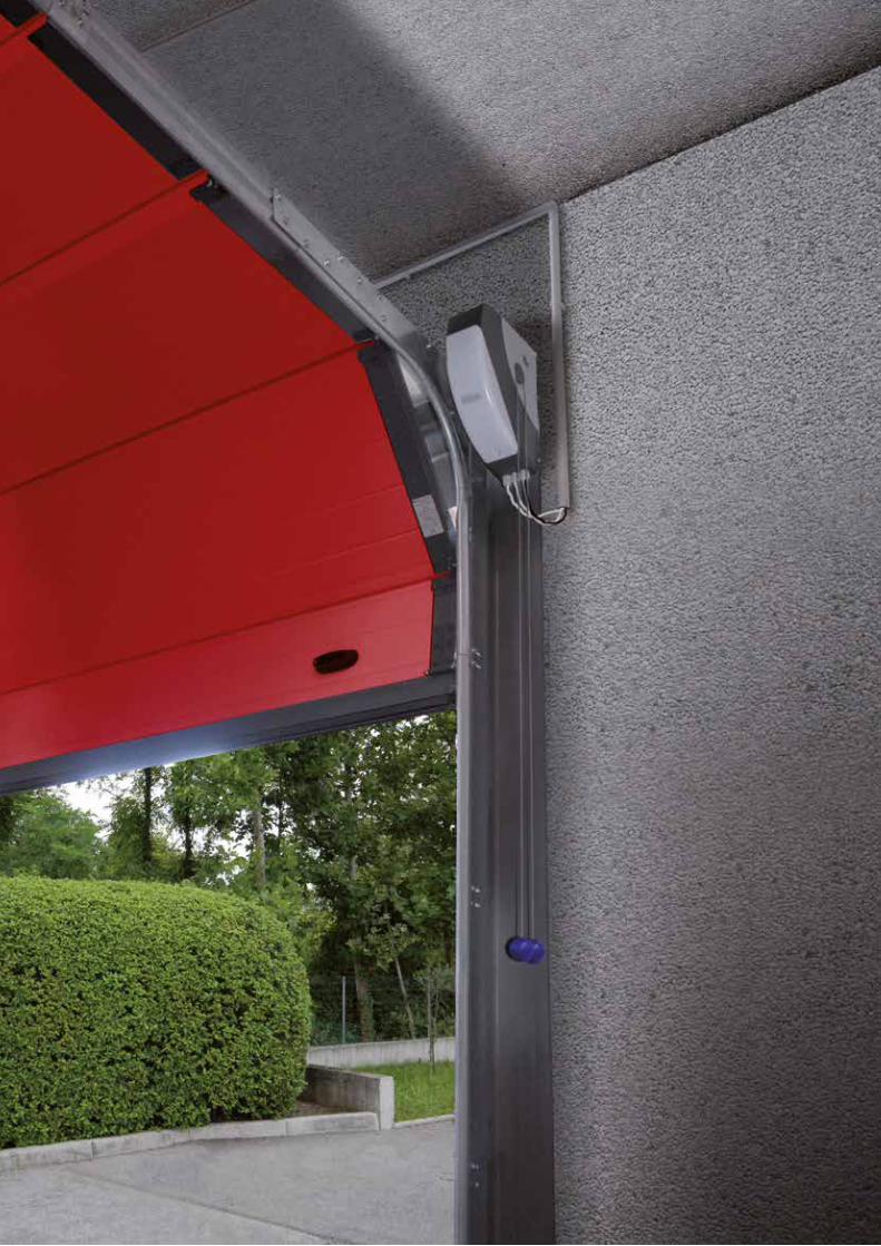
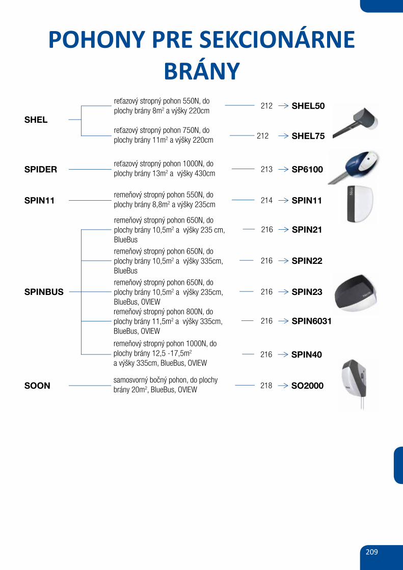
209
POHONY PRE SEKCIONÁRNEBRÁNY
SHEL
SPIN11
SPINBUS
SOON
reťazový stropný pohon 550N, do plochy brány 8m2 a výšky 220cm
212 SHEL50
reťazový stropný pohon 750N, do plochy brány 11m2 a výšky 220cm 212 SHEL75
remeňový stropný pohon 550N, doplochy brány 8,8m2 a výšky 235cm 214 SPIN11
remeňový stropný pohon 650N, doplochy brány 10,5m2 a výšky 235 cm,BlueBus
216 SPIN21
remeňový stropný pohon 650N, doplochy brány 10,5m2 a výšky 335cm,BlueBus
216 SPIN22
remeňový stropný pohon 650N, doplochy brány 10,5m2 a výšky 235cm,BlueBus, OVIEW
216 SPIN23
remeňový stropný pohon 800N, doplochy brány 11,5m2 a výšky 335cm,BlueBus, OVIEW
216 SPIN6031
remeňový stropný pohon 1000N, doplochy brány 12,5 -17,5m2
a výšky 335cm, BlueBus, OVIEW 216 SPIN40
samosvorný bočný pohon, do plochy brány 20m2, BlueBus, OVIEW 218 SO2000
SPIDERreťazový stropný pohon 1000N, do plochy brány 13m2 a výšky 430cm 213 SP6100
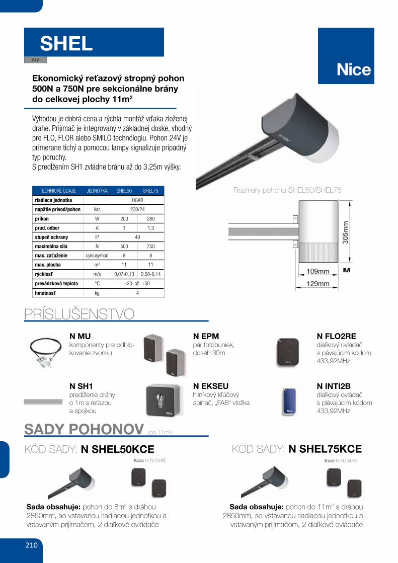
210
SHEL
Ekonomický reťazový stropný pohon500N a 750N pre sekcionálne bránydo celkovej plochy 11m2
Výhodou je dobrá cena a rýchla montáž vďaka zloženej dráhe. Prijímač je integrovaný v základnej doske, vhodný pre FLO, FLOR alebo SMILO technólogiu. Pohon 24V je primerane tichý a pomocou lampy signalizuje prípadný typ poruchy.S predĺžením SH1 zvládne bránu až do 3,25m výšky.
TECHNICKÉ ÚDAJE JEDNOTKA SHEL50 SHEL75
riadiaca jednotka OGA0
napätie prívod/pohon Vac 230/24
príkon W 200 280
prúd. odber A 1 1,3
stupeň ochrany IP 40
maximálna sila N 500 750
max. zaťaženie cyklusy/hod 8 8
max. plocha m2 11 11
rýchlosť m/s 0,07-0,13 0,08-0,14
prevádzková teplota °C -20 až +50
hmotnosť kg 4
PRÍSLUŠENSTVON MUkomponenty pre odblo-kovanie zvonku
N SH1predĺženie dráhyo 1m s reťazoua spojkou
N EPMpár fotobuniek,dosah 30m
N FLO2REdiaľkový ovládačs pávajúcim kódom 433,92MHz
N INTI2Bdiaľkový ovládačs plávajúcim kódom 433,92MHz
43
• SECTIONAL • SEZIONALE• SECTIONNELLE • SECCIONAL
• SEKTIONALTOR• BRAMA SEGMENTOWA
• SECTIONAAL
• PROJECTING • DEBORDANTE• DÉBORDANTE • DESBORDANTE
• AUSFAHREND • WYSTAJĄCA• BUITEN DE GEVEL DRAAIEND
• NON-PROJECTING • NON DE-BORDANTE• NON DÉBORDANTE
• NO DESBORDANTE • NICHT AU-SFAHREND • NIEWYSTAJĄCA
• BINNEN DE GEVEL BLIJVEND
a b c
d
fe
g h i l m
on p q
BFB
EA
D65 ÷ 100 mm
5
M
D
G
1
2
r
X
Rozmery pohonu SHEL50/SHEL75
N EKSEUhliníkový kľúčovýspínač, „FAB“ vložka
58 GATE&DOOR 2013
≥ 130
≥ 300
B ≥ 710 mmA ≥ 450
B ≤
450
A ≤
350
hyPPO 7000
800
700
600
500
400
300
2002 2,5 3
HY7005
HY7005 / HY7024
165350 mm
242
9015
2
230V24VbLuEbusOPERAsOLEmyO
hy7024 hy7005
- 23024 -5 1.2
120 250
2 1.7250 40080 30
43-20 ÷ +50
350x165x242 h13
For swing gates with leaves up to 3 m, also ideal for large pillars. Electromechanical gear motor, surface mounted, also in 24 Vdc version with magnetic encoder, with articulated arm.
Single model for right and left leaves. Two irreversible versions, with 230 Vac (HY7005) and 24 Vdc (HY7024) power supplies with magnetic encoder.
Fewer connections mean quicker installation.
Pre-wired, incorporated double limit-switch both during opening and closing (HY7005).
mAx
. GAT
E W
EIGh
T (k
G)
mAx. GATE LENGTh (m)
N.B. The above values are valid if the motor is used with standard accessories. The shape, the height of the gate and the weather conditions can considerably reduce the values shown in the graph to the side. Use in windy areas 230 Vac models.
CODE DESCRIPTION PACK/PALLET
hy7024 IRREVERSIBLE, 24 Vdc, WITH MAGNETIC ENCODER, WITH SHEAR-PROOF ARTICULATED ARM, GALVANIZED AND PAINTED
16
hy7005 IRREVERSIBLE, 230 Vac, WITH STURDY ARTICULATED SHEAR-PROOF ARM, GALVANIZED AND PAINTED, WITH LIMIT SWITCH ON OPENING AND CLOSING
16
Easy and quick to install: thanks to fewer connections and nothing welded to the gates.
Long-lasting: solid metal mechanics.
Compact: shockproof bodywork with no sharp corners.
Recommended control units: Mindy A6F, A60, A700F; for HY7024 Moonclever MC824H.
24 Vdc version with magnetic encoder. Perfect for intensive use, compatible with the control unit Moonclever MC824H: • simple programming, by means of a single key; • self-learning of opening and closing limit positions; • automatic fault diagnostics; • programming of pause time; • pedestrian pass door; • deceleration on opening and closing; • obstacle detection with dual technology; • operation in event of power failure by means of optional rechargeable batteries (PS324); • provision for connection of latest generation resistive sensitive edges.
TEChNICAL sPECIFICATIONsCODEELECTRICAL DATAPOWER SUPPLY (Vac 50 Hz)*POWER SUPPLY (Vdc)ABSORPTION (A)POWER (W)PERFORmANCE DATASPEED (rpm)TORqUE (Nm)WORK CYCLE (%)DImENsIONAL AND GENERAL DATAPROTECTION LEVEL (IP)WORKING TEMP. (°C MIN/MAx)DIMENSIONS (mm)WEIGHT (kg)
*60 Hz version available on request.
A Standard armb Arm with accessory HYA12
uTILIsATION LImITs DImENsIONs
STURDY, ANTI-SHEARING ARM, GALVANISED AND PAINTED; STRENGTHENED IN THOSE AREAS SUBjECTED TO GREATER MECHANICAL STRESS
DIE-CAST, ALUMINIUM, KEY-OPERATED UNLOCK SYSTEM, COMPLETE WITH PROTECTED KEY. DESIGNED TO ACCOMMODATE ExTERNAL RELEASE, TOO
24V
SADY POHONOV (do 11m2)
KÓD SADY: N SHEL50KCE
Sada obsahuje: pohon do 8m2 s dráhou 2850mm, so vstavanou riadiacou jednotkou a vstavaným prijímačom, 2 diaľkové ovládače
Kód: N FLO4RE
KÓD SADY: N SHEL75KCE
Sada obsahuje: pohon do 11m2 s dráhou 2850mm, so vstavanou riadiacou jednotkou a
vstavaným prijímačom, 2 diaľkové ovládače
Kód: N FLO4RE
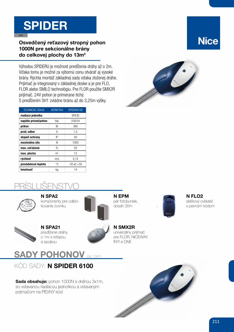
211
SPIDEROsvedčený reťazový stropný pohon 1000N pre sekcionálne bránydo celkovej plochy do 13m2
Výhodou SPIDERU je možnost predĺženia dráhy až o 2m. Vďaka tomu je možné za výbornú cenu otvárať aj vysoké brány. Rýchla montáž základnej sady vďaka zloženej dráhe. Prijímač je integrovaný v základnej doske a je pre FLO, FLOR alebo SMILO technológiu. Pre FLOR použite SMX2R prijímač. 24V pohon je primerane tichý.S predĺžením SH1 zvládne bránu až do 3,25m výšky.
TECHNICKÉ ÚDAJE JEDNOTKA SPIDER6100
riadiaca jednotka SPA30
napätie prívod/pohon Vac 230/24
príkon W 360
prúd. odber A 1,5
stupeň ochrany IP 40
maximálna sila N 1000
max. zaťaženie % 20
max. plocha m2 13
rýchlosť m/s 0,14
prevádzková teplota °C -20 až +50
hmotnosť kg 14
PRÍSLUŠENSTVON SPA2komponenty pre odblo-kovanie zvonku
N SPA21predĺženie dráhyo 1m s reťazoua spojkou
N EPMpár fotobuniek,dosah 30m
N FLO2diaľkový ovládačs pevným kódom
N SMX2Runiverzálny prijímač pre FLOR, NICEWAY, INTI a ONE
24V
SADY POHONOV (do 13m2)
KÓD SADY: N SPIDER 6100
Sada obsahuje: pohon 1000N s dráhou 3x1m,so vstavanou riadiacou jednotkou a vstavaným prijímačom na PEVNÝ kód
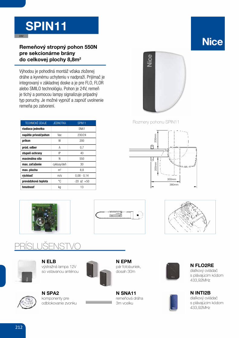
212
SPIN11
Remeňový stropný pohon 550N pre sekcionárne bránydo celkovej plochy 8,8m2
Výhodou je pohodlná montáž vďaka zloženej dráhe a kyvnému uchyteniu v nadpraží. Prijímač je integrovaný v základnej doske a je pre FLO, FLOR alebo SMILO technológiu. Pohon je 24V, remeň je tichý a pomocou lampy signalizuje prípadný typ poruchy. Je možné vypnúť a zapnúť uvolnenie remeňa po zatvorení.
TECHNICKÉ ÚDAJE JEDNOTKA SPIN11
riadiaca jednotka SNA1
napätie prívod/pohon Vac 230/24
príkon W 200
prúd. odber A 0,7
stupeň ochrany IP 40
maximálna sila N 550
max. zaťaženie cyklusy/deň 30
max. plocha m2 8,8
rýchlosť m/s 0,08 - 0,14
prevádzková teplota °C -20 až +50
hmotnosť kg 13
PRÍSLUŠENSTVO
N ELBvýstražná lampa 12Vso vstavanou anténou
N SPA2komponenty preodblokovanie zvonku
N EPMpár fotobuniek,dosah 30m
N SNA11remeňová dráha3m vcelku
N FLO2REdiaľkový ovládačs plávajúcim kódom 433,92MHz
N INTI2Bdiaľkový ovládačs plávajúcim kódom 433,92MHz
6
3.1) Preliminary checksBefore proceeding with the installation of SPIN you must:• Verify and ensure after installation that no door parts obstruct pub-
lic roadways or pavements.• Check that all the materials are in excellent condition, suitable for
use and that they conform to the standards currently in force. • Make sure that the structure of the gate is suitable for automation.• Make sure that the force and dimensions of the door fall within the
specified operating limits provided in chapter “2.1 Operating limits”.• Check that the static friction (that is, the force required to start the
movement of the leaf) is less than half the “maximum torque”, andthat the dynamic friction (that is, the force required to keep the leafin movement) is less than half the "nominal torque”. Compare theresulting values with those specified in Chapter 8 “Technical Char-acteristics”. The manufacturer recommends a 50% margin on theforce, as unfavourable climatic conditions may cause an increasein the friction.
• Make sure that there are no points of greater friction in the open-ing or closing travel of the door.
• Make sure that the mechanical stops are sturdy enough, and thatthere is no danger of door derailing.
• Make sure that the door is well balanced: it must not move by itselfwhen it is placed in any position.
• Make sure that the mounting positions of the various devices (pho-tocells, keys, etc.) are protected from impacts and that the mount-ing surfaces are sufficiently sturdy.
• Make sure that the minimum and maximum clearances specifiedin fig. 5 and 6 are observed.
• Check and ensure that the manual release is fitted at a maximumheight of 1.8 m.
• Components must never be immersed in water or other liquids.• Keep all components of SPIN away from heat sources and open
flames; these could damage the components and cause malfunc-tions, fire or dangerous situations.
• If the door includes an access door, make sure that it does notobstruct normal travel. Mount a suitable interlock system if neces-sary.
• If the door to be automated is an overhead type, check the dis-tance [E] in Figure 7, i.e. the minimum distance between the upperside of the guide and the maximum point reached by the upperedge of the door. Otherwise SPIN cannot be installed.
• Connect SPIN only to a power supply line equipped with safetygrounding system.
• The power supply line must be protected by suitable magneto-thermal and differential switches.
7
3.2) Fitting SPINFixture of the SPIN gearmotor comprises 3 stages.• Guide assembly (see paragraph 3.2.1 for guides supplied with
SPIN10KCE and paragraph 3.2.2 for guide SNA11)• Mounting the gearmotor to the guide (see paragraph 3.2.3)• Mounting the gearmotor to the ceiling (see paragraph 3.2.4)
The installation of SPIN must be carried out by qualifiedpersonnel in compliance with current legislation, stan-dards and regulations, and the directions provided in thismanual.
!
3) Installation
5
6
200m
m
300mm
380mm
E 65÷300 mm
C 2970mm D 380mm
B 0÷400mm
A40
÷40
0mm
200m
m
Rozmery pohonu SPIN11
7
GB
B
3.2.1) Assembly of guide supplied with SPIN10KCEThe guide that is supplied with SPIN10KCE must be assembled as follows:1. Referring to figure 8, remove the belt tensioner device (8a); insert one end of the belt into the pulley (8b); reintroduce the belt tensioner
device into the guide (8c).
4. Position both ends of the belt into all of the shaped slots of the lower carriage (C). Secure the ends of the belt with the 2 screws (V4.2x9.5)and 2 washers (R05), as in figure 11.
5. Fix the belt guide (D) to the upper carriage (E) with the V6x18 screw and related M6 nut, as in figure 12.6. Insert the upper carriage (E)into the lower carriage (C) and place the entire carriage assembly inside the guide, as in figure 13.
7. With the aid of a hammer, assemble the three pieces of the guide engaging them into the connection brackets (F) with force, as in fig-ures 14 and 15.Important: the guides must slide into the brackets until they click into position.
8. Carefully position the belt into the guide, making sure that it is not twisted.9. Fix the head (B) into the free end of the guide with force, as in figure 16.10.Finally, tension the belt with the adjustment screw (H) of the belt tensioner device, as in figure 17.
Warning: the gearmotor could break if the belt is too taut and if it is too slack, it could cause unpleasant noise.
11 12 13
C
14 16 17
H
D
E
E
C
8A 8B 8C
10
A
B
9
A
A
2. Pass the same end of the belt through the head (B), as in figure 9.Note: Make sure that the belt is correctly positioned: it must be with the teeth facing inwards, straight and without twists.
3. Turn the lower section of the carriage so that the grooves correspond with the two ends of the belt, as in figure 10.
F
15
10
3.4) Electrical connectionsBefore you proceed to make any electrical connections
make sure that the power supply is disconnected.
1. Open the protection cover in order to access the electronic con-trol unit of the SPIN. To do this, press the side and rotate asshown in figure 31.
2. Insert all the connection cables towards the various devicesthrough the hole, leaving a length of 20÷30 cm longer than nec-essary. See Table 5 for information regarding the type of cablesand Figure 2 for the connections.
3. Connect up the cables according to the diagram in Figure 33.
!
31 32
33
LUCYB
MOSE
24V
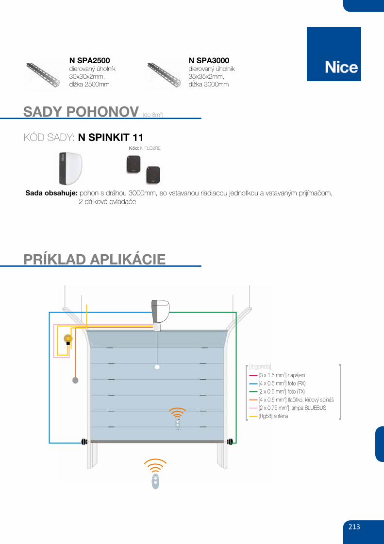
213
SADY POHONOV (do 8m2)
KÓD SADY: N SPINKIT 11
Sada obsahuje: pohon s dráhou 3000mm, so vstavanou riadiacou jednotkou a vstavaným prijímačom, 2 dálkové ovladače
Kód: N FLO2RE
[3 x 1.5 mm ]2
napájení
[4 x 0.5 mm ] foto (RX)2
[4 x 0.5 mm ]2
tlačítko, klíčový spínáš
[2 x 0.75 mm ] lampa BLUEBUS2
[Rg58] ant naé
[legenda]
[2 x 0.5 mm ] foto (TX)2
MLBlampa sygnalizacyjna BLUEBUS
12V z wbudowaną anteną 433.92 MHz
110,00
135,30 brutto
110,00
135,30 brutto
MLBTlampa sygnalizacyjna BLUEBUS
12V z wbudowaną anteną 433.92 MHz
SPA 2
FT210
BFLUCYBzestaw wysprzęglania
z zewnątrz do SPIN/SPIDO
fotokomórki (para-bez baterii),
nastawne z kątem 210°,
zasięg 15 m
fotokomórka (para) zasięg 15-30mlampa sygnalizacyjna BLUEBUS
12V z wbudowaną anteną 433.92 MHz
80,00
98,40 brutto
350,00
430,50 brutto
160,00
196,80 brutto
100,00
123,00 brutto
WYMIARY
SPIN11
AKCESORIA
PRZYKŁADOWY ZESTAW DO UŻYTKU PRZYDOMOWEGO
FLO2RE1 pilot dwukanałowy
433.92 MHz
SNA11jednoelementowa szyna
1x3m
SPIN11 ERA FLOR
330100
225
PARAMETRY BRAMY
SPIN11KCE 2.2 m 3.5 m 2.35 m 3.7 m
BR
AM
A G
AR
AŻ
OW
A
UC
HY
LN
A
BR
AM
Y G
AR
AŻ
OW
E
SE
KC
YJN
E
wys. szer. wys. szer.
|81AUTOMATYKA DO BRAM GARAŻOWYCH
POZOSTAŁE AKCESORIA STR. 96-105
siłownik 550N do bramy garażowej o wys. do 235 cm
z wbudowanym radiem 433.92 MHz (multikod)
PRÍKLAD APLIKÁCIE
N SPA2500dierovaný úholník30x30x2mm,dĺžka 2500mm
N SPA3000dierovaný úholník35x35x2mm,dĺžka 3000mm
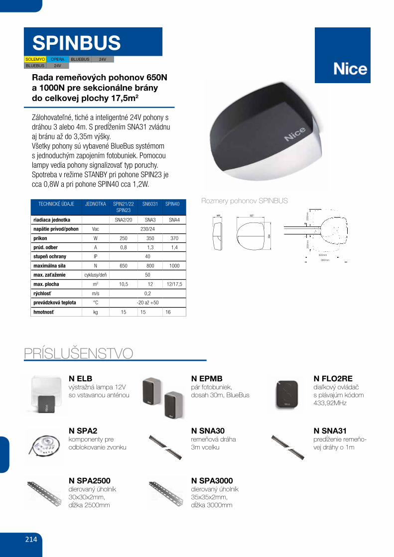
214
SPINBUS
Rada remeňových pohonov 650Na 1000N pre sekcionálne bránydo celkovej plochy 17,5m2
Zálohovateľné, tiché a inteligentné 24V pohony s dráhou 3 alebo 4m. S predĺžením SNA31 zvládnu aj bránu až do 3,35m výšky.Všetky pohony sú vybavené BlueBus systémom s jednoduchým zapojením fotobuniek. Pomocou lampy vedia pohony signalizovať typ poruchy.Spotreba v režime STANBY pri pohone SPIN23 je cca 0,8W a pri pohone SPIN40 cca 1,2W.
TECHNICKÉ ÚDAJE JEDNOTKA SPIN21/22SPIN23
SN6031 SPIN40
riadiaca jednotka SNA2/20 SNA3 SNA4
napätie prívod/pohon Vac 230/24
príkon W 250 350 370
prúd. odber A 0,8 1,3 1,4
stupeň ochrany IP 40
maximálna sila N 650 800 1000
max. zaťaženie cyklusy/deň 50
max. plocha m2 10,5 12 12/17,5
rýchlosť m/s 0,2
prevádzková teplota °C -20 až +50
hmotnosť kg 15 15 16
6
3.1) Preliminary checksBefore proceeding with the installation of SPIN you must:• Check that all the materials are in excellent condition, suitable for
use and that they conform to the standards currently in force. • Make sure that the structure of the door is suitable for automation.• Make sure that the force and dimensions of the door fall within the
specified operating limits provided in chapter “2.1 Operating lim-its”.
• Check that the static friction (that is, the force required to start themovement of the leaf) is less than half the “maximum torque”, andthat the dynamic friction (that is, the force required to keep the leafin movement) is less than half the “nominal torque”. Compare theresulting values with those specified in Chapter “8 Technical Char-acteristics”. The manufacturers recommend a 50% margin on theforce, as unfavourable climatic conditions may cause an increasein the friction.
• Make sure that there are no points of greater friction in the open-ing or closing travel of the door leaves.
• Make sure that the mechanical stops are sturdy enough, and thereis no danger of the door derailing.
• Check that the door is well balanced, i.e. does not move if left inany position.
• Make sure that the mounting positions of the various devices (pho-tocells, buttons, etc.) are protected from impacts and that themounting surfaces are sufficiently sturdy.
• Check and ensure minimum and maximum clearances as shownin figures 5 and 6
• Never immerse components in water or other liquids• Keep SPIN components away from sources of heat and open
flames; situations such as these could damage SPIN and causeeither malfunctions, fires or dangerous situations.
• If the door includes an access door, make sure that it does notobstruct normal travel. Mount a suitable interlock system if neces-sary.
• If the door to be automated is an overhead version, check value Eshown in figure 7, i.e. the minimum distance between the upperside of the guide and the maximum point reached by the upperedge of the door. If the value does not correspond, SPIN cannotbe fitted.
• Connect the SPIN power plug to a suitably earthed mains socket.• The electrical socket must be protected by means of an adequate
thermal magnetic cut-out device.
7
3.2) Fitting SPINFixture of the SPIN gearmotor comprises 3 stages:• Guide assembly (see paragraph 3.2.1 for guides supplied with
SPIN20KCE, SPIN30 and SPIN40, paragraph 3.2.2 for guideSNA5 and paragraph 3.2.3 for guide SNA6)
• Fixture of gearmotor to guide (see paragraph 3.2.4)• Fixture of gearmotor to ceiling (see paragraph 3.2.5)
SN6031 requires a SNA5 or a SNA6 guide, while SN6041requires a SNA6 guide.
!
The installation of SPIN must be carried out by qualifiedpersonnel in compliance with current legislation, standardsand regulations, and the directions provided in this manual.
!
3) Installation
5
6
200m
m
300mm
380mm
E 65÷300 mm
C 2970mm D 380mm
B 0÷400mm
A40
÷40
0mm
200m
m
PRÍSLUŠENSTVO
PS124
MLB
akumulator 24V 1.2 Ah
z wbudowaną kartą ładowania
do SN6031/SN6041/SPIN40/SPIN23
lampa sygnalizacyjna BLUEBUS
12V z wbudowaną anteną 433.92 MHz
110,00
135,30 brutto
SPA 2SNA 30
FT210B MOFB
OTA11
LUCYB
SNA 6zestaw wysprzęglania
z zewnątrz do SPIN/SPIDO
jednoelementowa szyna stalowa
3 m, z paskiem zbrojonym
fotokomórki (para-bez baterii),
BLUEBUS nastawne z kątem 210°,
zasięg 15 m
fotokomórki (para) BLUEBUS,
zasięg 15-30 m
zestaw wysprzęglania
z zewnątrz do SPIN/SPIDO
z dłuższą linką
lampa sygnalizacyjna BLUEBUS
12V z wbudowaną anteną 433.92 MHz
dwuelementowa szyna stalowa
3 m + 1 m, z paskiem zbrojonym
80,00
98,40 brutto
330,00
405,90 brutto
350,00
430,50 brutto
190,00
233,70 brutto
90,00
110,70 brutto
290,00
356,70 brutto
100,00
123,00 brutto
500,00
615,00 brutto
AKCESORIA
PRZYKŁADOWY ZESTAW DO UŻYTKU PRZYDOMOWEGO
FLO2RE1 pilot dwukanałowy
433.92 MHz
SNA30SPIN21 ERA FLORsiłownik 550N do bramy garażowej o wys. do 235 cm
do 235 cm od 235 cm
do 340 cm
PARAMETRY BRAMY
327105
324
SPIN21KCE 2.2 m 4.2 m 2.35 m 4.4 m
SPIN22KCE 3.2 m 2.9 m 3.4 m 3.1 m
wys. szer. wys. szer.
BR
AM
A G
AR
AŻ
OW
A
UC
HY
LN
A
BR
AM
Y G
AR
AŻ
OW
E
SE
KC
YJN
E
|83AUTOMATYKA DO BRAM GARAŻOWYCH
POZOSTAŁE AKCESORIA STR. 96-105
SMXIradioodbiornik wewnętrzny,
4-kanałowy 433.92 MHz
Rozmery pohonov SPINBUS
N ELBvýstražná lampa 12Vso vstavanou anténou
N SPA2komponenty preodblokovanie zvonku
PS124
MLB
akumulator 24V 1.2 Ah
z wbudowaną kartą ładowania
do SN6031/SN6041/SPIN40/SPIN23
lampa sygnalizacyjna BLUEBUS
12V z wbudowaną anteną 433.92 MHz
110,00
135,30 brutto
SPA 2SNA 30
FT210B MOFB
OTA11
LUCYB
SNA 6zestaw wysprzęglania
z zewnątrz do SPIN/SPIDO
jednoelementowa szyna stalowa
3 m, z paskiem zbrojonym
fotokomórki (para-bez baterii),
BLUEBUS nastawne z kątem 210°,
zasięg 15 m
fotokomórki (para) BLUEBUS,
zasięg 15-30 m
zestaw wysprzęglania
z zewnątrz do SPIN/SPIDO
z dłuższą linką
lampa sygnalizacyjna BLUEBUS
12V z wbudowaną anteną 433.92 MHz
dwuelementowa szyna stalowa
3 m + 1 m, z paskiem zbrojonym
80,00
98,40 brutto
330,00
405,90 brutto
350,00
430,50 brutto
190,00
233,70 brutto
90,00
110,70 brutto
290,00
356,70 brutto
100,00
123,00 brutto
500,00
615,00 brutto
AKCESORIA
PRZYKŁADOWY ZESTAW DO UŻYTKU PRZYDOMOWEGO
FLO2RE1 pilot dwukanałowy
433.92 MHz
SNA30SPIN21 ERA FLORsiłownik 550N do bramy garażowej o wys. do 235 cm
do 235 cm od 235 cm
do 340 cm
PARAMETRY BRAMY
327105
324
SPIN21KCE 2.2 m 4.2 m 2.35 m 4.4 m
SPIN22KCE 3.2 m 2.9 m 3.4 m 3.1 m
wys. szer. wys. szer.
BR
AM
A G
AR
AŻ
OW
A
UC
HY
LN
A
BR
AM
Y G
AR
AŻ
OW
E
SE
KC
YJN
E
|83AUTOMATYKA DO BRAM GARAŻOWYCH
POZOSTAŁE AKCESORIA STR. 96-105
SMXIradioodbiornik wewnętrzny,
4-kanałowy 433.92 MHz
N EPMBpár fotobuniek,dosah 30m, BlueBus
N SNA30remeňová dráha3m vcelku
N FLO2REdiaľkový ovládač s plávajúm kódom 433,92MHz
N SNA31predĺženie remeňo-vej dráhy o 1m
PS124
MLB
akumulator 24V 1.2 Ah
z wbudowaną kartą ładowania
do SN6031/SN6041/SPIN40/SPIN23
lampa sygnalizacyjna BLUEBUS
12V z wbudowaną anteną 433.92 MHz
110,00
135,30 brutto
SPA 2SNA 30
FT210B MOFB
OTA11
LUCYB
SNA 6zestaw wysprzęglania
z zewnątrz do SPIN/SPIDO
jednoelementowa szyna stalowa
3 m, z paskiem zbrojonym
fotokomórki (para-bez baterii),
BLUEBUS nastawne z kątem 210°,
zasięg 15 m
fotokomórki (para) BLUEBUS,
zasięg 15-30 m
zestaw wysprzęglania
z zewnątrz do SPIN/SPIDO
z dłuższą linką
lampa sygnalizacyjna BLUEBUS
12V z wbudowaną anteną 433.92 MHz
dwuelementowa szyna stalowa
3 m + 1 m, z paskiem zbrojonym
80,00
98,40 brutto
330,00
405,90 brutto
350,00
430,50 brutto
190,00
233,70 brutto
90,00
110,70 brutto
290,00
356,70 brutto
100,00
123,00 brutto
500,00
615,00 brutto
AKCESORIA
PRZYKŁADOWY ZESTAW DO UŻYTKU PRZYDOMOWEGO
FLO2RE1 pilot dwukanałowy
433.92 MHz
SNA30SPIN21 ERA FLORsiłownik 550N do bramy garażowej o wys. do 235 cm
do 235 cm od 235 cm
do 340 cm
PARAMETRY BRAMY
327105
324
SPIN21KCE 2.2 m 4.2 m 2.35 m 4.4 m
SPIN22KCE 3.2 m 2.9 m 3.4 m 3.1 m
wys. szer. wys. szer.
BR
AM
A G
AR
AŻ
OW
A
UC
HY
LN
A
BR
AM
Y G
AR
AŻ
OW
E
SE
KC
YJN
E
|83AUTOMATYKA DO BRAM GARAŻOWYCH
POZOSTAŁE AKCESORIA STR. 96-105
SMXIradioodbiornik wewnętrzny,
4-kanałowy 433.92 MHz
SOLEMYO OPERA BLUEBUS 24V
BLUEBUS 24V
N SPA2500dierovaný úholník30x30x2mm,dĺžka 2500mm
N SPA3000dierovaný úholník35x35x2mm,dĺžka 3000mm
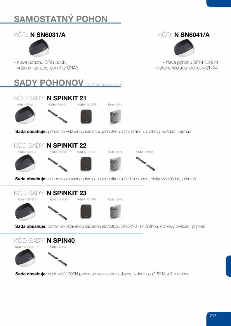
215
SAMOSTATNÝ POHON
- hlava pohonu SPIN 800N- vrátane riadiacej jednotky SNA3
SADY POHONOV (do 17,5m2 plochy brány)
KÓD SADY: N SPINKIT 21
Sada obsahuje: pohon so vstavanou riadiacou jednotkou a 3m dráhou, diaľkový ovládač, prijímač
Kód: N FLO2RE Kód: N SMXI
KÓD: N SN6031/A
KÓD SADY: N SPINKIT 22
Sada obsahuje: pohon so vstavanou riadiacou jednotkou a 3+1m dráhou, diaľkový ovládač, prijímač
Kód: N FLO2RE Kód: N SMXI Kód: N SNA31
KÓD SADY: N SPINKIT 23
Sada obsahuje: pohon so vstavanou riadiacou jednotkou OPERA a 3m dráhou, diaľkový ovládač, prijímač
Kód: N FLO2RE Kód: N SMXI
KÓD SADY: N SPIN40
Sada obsahuje: najsilnejší 1000N pohon so vstavanou riadiacou jednotkou OPERA a 3m dráhou
PS124
MLB
akumulator 24V 1.2 Ah
z wbudowaną kartą ładowania
do SN6031/SN6041/SPIN40/SPIN23
lampa sygnalizacyjna BLUEBUS
12V z wbudowaną anteną 433.92 MHz
110,00
135,30 brutto
SPA 2SNA 30
FT210B MOFB
OTA11
LUCYB
SNA 6zestaw wysprzęglania
z zewnątrz do SPIN/SPIDO
jednoelementowa szyna stalowa
3 m, z paskiem zbrojonym
fotokomórki (para-bez baterii),
BLUEBUS nastawne z kątem 210°,
zasięg 15 m
fotokomórki (para) BLUEBUS,
zasięg 15-30 m
zestaw wysprzęglania
z zewnątrz do SPIN/SPIDO
z dłuższą linką
lampa sygnalizacyjna BLUEBUS
12V z wbudowaną anteną 433.92 MHz
dwuelementowa szyna stalowa
3 m + 1 m, z paskiem zbrojonym
80,00
98,40 brutto
330,00
405,90 brutto
350,00
430,50 brutto
190,00
233,70 brutto
90,00
110,70 brutto
290,00
356,70 brutto
100,00
123,00 brutto
500,00
615,00 brutto
AKCESORIA
PRZYKŁADOWY ZESTAW DO UŻYTKU PRZYDOMOWEGO
FLO2RE1 pilot dwukanałowy
433.92 MHz
SNA30SPIN21 ERA FLORsiłownik 550N do bramy garażowej o wys. do 235 cm
do 235 cm od 235 cm
do 340 cm
PARAMETRY BRAMY
327105
324
SPIN21KCE 2.2 m 4.2 m 2.35 m 4.4 m
SPIN22KCE 3.2 m 2.9 m 3.4 m 3.1 m
wys. szer. wys. szer.
BR
AM
A G
AR
AŻ
OW
A
UC
HY
LN
A
BR
AM
Y G
AR
AŻ
OW
E
SE
KC
YJN
E
|83AUTOMATYKA DO BRAM GARAŻOWYCH
POZOSTAŁE AKCESORIA STR. 96-105
SMXIradioodbiornik wewnętrzny,
4-kanałowy 433.92 MHz
- hlava pohonu SPIN 1000N- vrátane riadiacej jednotky SNA4
KÓD: N SN6041/A
PS124
MLB
akumulator 24V 1.2 Ah
z wbudowaną kartą ładowania
do SN6031/SN6041/SPIN40/SPIN23
lampa sygnalizacyjna BLUEBUS
12V z wbudowaną anteną 433.92 MHz
110,00
135,30 brutto
SPA 2SNA 30
FT210B MOFB
OTA11
LUCYB
SNA 6zestaw wysprzęglania
z zewnątrz do SPIN/SPIDO
jednoelementowa szyna stalowa
3 m, z paskiem zbrojonym
fotokomórki (para-bez baterii),
BLUEBUS nastawne z kątem 210°,
zasięg 15 m
fotokomórki (para) BLUEBUS,
zasięg 15-30 m
zestaw wysprzęglania
z zewnątrz do SPIN/SPIDO
z dłuższą linką
lampa sygnalizacyjna BLUEBUS
12V z wbudowaną anteną 433.92 MHz
dwuelementowa szyna stalowa
3 m + 1 m, z paskiem zbrojonym
80,00
98,40 brutto
330,00
405,90 brutto
350,00
430,50 brutto
190,00
233,70 brutto
90,00
110,70 brutto
290,00
356,70 brutto
100,00
123,00 brutto
500,00
615,00 brutto
AKCESORIA
PRZYKŁADOWY ZESTAW DO UŻYTKU PRZYDOMOWEGO
FLO2RE1 pilot dwukanałowy
433.92 MHz
SNA30SPIN21 ERA FLORsiłownik 550N do bramy garażowej o wys. do 235 cm
do 235 cm od 235 cm
do 340 cm
PARAMETRY BRAMY
327105
324
SPIN21KCE 2.2 m 4.2 m 2.35 m 4.4 m
SPIN22KCE 3.2 m 2.9 m 3.4 m 3.1 m
wys. szer. wys. szer.
BR
AM
A G
AR
AŻ
OW
A
UC
HY
LN
A
BR
AM
Y G
AR
AŻ
OW
E
SE
KC
YJN
E
|83AUTOMATYKA DO BRAM GARAŻOWYCH
POZOSTAŁE AKCESORIA STR. 96-105
SMXIradioodbiornik wewnętrzny,
4-kanałowy 433.92 MHz
Kód: N SNA30Kód: N SPIN23
Kód: N SNA30Kód: N SPIN22
Kód: N SNA30Kód: N SPIN21
Kód: N SNA30Kód: N SPIN6041/A
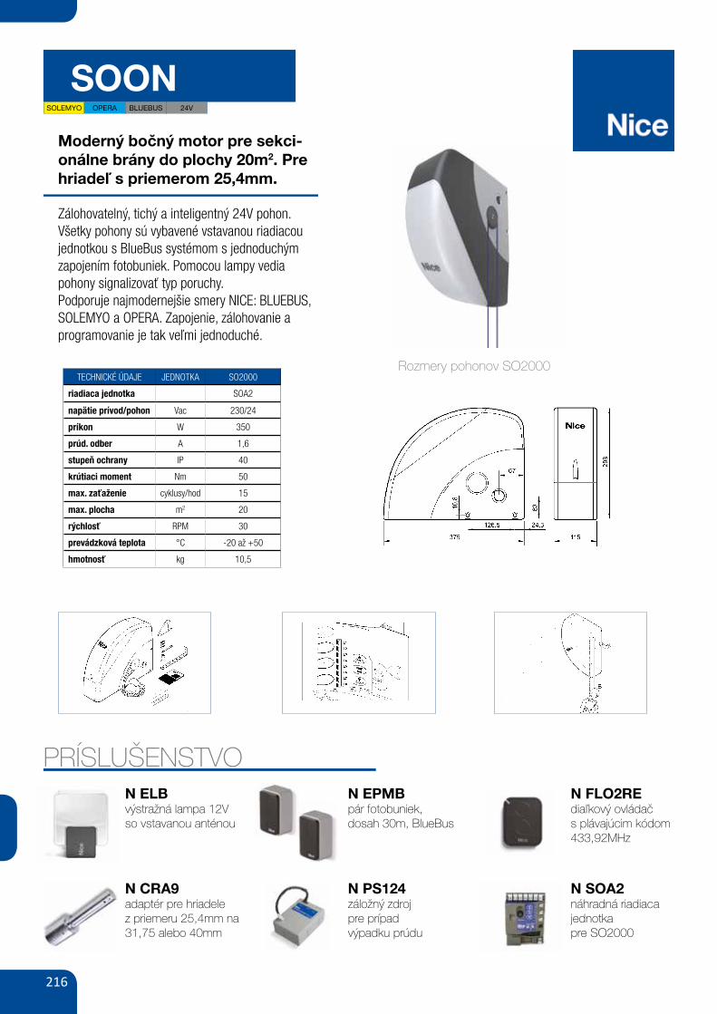
216
SOON
Moderný bočný motor pre sekci-onálne brány do plochy 20m2. Pre hriadeľ s priemerom 25,4mm.
Zálohovatelný, tichý a inteligentný 24V pohon.Všetky pohony sú vybavené vstavanou riadiacou jednotkou s BlueBus systémom s jednoduchým zapojením fotobuniek. Pomocou lampy vedia pohony signalizovať typ poruchy.Podporuje najmodernejšie smery NICE: BLUEBUS, SOLEMYO a OPERA. Zapojenie, zálohovanie a programovanie je tak veľmi jednoduché.
TECHNICKÉ ÚDAJE JEDNOTKA SO2000
riadiaca jednotka SOA2
napätie prívod/pohon Vac 230/24
príkon W 350
prúd. odber A 1,6
stupeň ochrany IP 40
krútiaci moment Nm 50
max. zaťaženie cyklusy/hod 15
max. plocha m2 20
rýchlosť RPM 30
prevádzková teplota °C -20 až +50
hmotnosť kg 10,5
PRÍSLUŠENSTVO
4
Before proceeding with installation, check the condition of the product components, suitability of the selected model and conditions of theintended installation environment.
3) Installation feasibility check
3.1) Check product components (see fig. 1)Check the condition of the packaging:unpack the product and ensure presence of:- 1 Soon gearmotor- 1 fixing bracket- 4 release half-rings- 2 keys- 1 M8x130 screw- 1 M8 locknut- 1 D8 washer- 1 gear- 3 black self-tapping screws- 1 instruction manual
Installation of the automation must be performed exclusively by qualified personnel, in observance of current legis-lation and standards governing these operations, and according to the instructions in this manual.
!
4) Install the various components
4.1) Standard installation layout (see fig. 3)Fig. 3 illustrates the complete installation of a Soon gearmotor. The drawing shows the various components and cables required for con-nection, all assembled and positioned according to a standard layout.
Key to mechanical components in Fig. 3:1 - Soon gearmotor2 - Photocell3 - Key-operated selector switch4 - Post for photocell5 - Flashing light6 - Transmitter7 - Main edge
Key to electric cables in Fig. 3:A - Electric power lineB - Flashing light with aerialC - PhotocellsD - Key-operated selector switchE - Main edge
1
3.3) Check product application limits (see fig. 2)Check the application limits of the Soon model and relative acces-sories to be installed, assessing suitability of the characteristics tomeet the requirements of the environment and the limitations speci-fied below.• Ensure that the size of the sectional door is less than 20 m2.• Ensure that the section door drive shaft is compatible with the
Soon outlet shaft, using the keys provided in the pack.• Ensure that the wall fixing brackets are sufficiently long.
3.2) Check suitability of environment• Check that the selected site of installation is compatible with the
overall dimensions of the Soon model (Fig. 2).• Check that there are no obstacles along the trajectory of the sec-
tion door, which could obstruct total opening and closing move-ments.
• Check that the selected site of installation enables easy and safeexecution of manual manoeuvres
• Check that each device to be fixed is positioned on a solid surfaceprotected from the risk of accidental impact.
2
Rozmery pohonov SO2000
N ELBvýstražná lampa 12Vso vstavanou anténou
N CRA9adaptér pre hriadelez priemeru 25,4mm na 31,75 alebo 40mm
N EPMBpár fotobuniek,dosah 30m, BlueBus
N PS124záložný zdrojpre prípadvýpadku prúdu
N FLO2REdiaľkový ovládačs plávajúcim kódom 433,92MHz
N SOA2náhradná riadiacajednotkapre SO2000
6
4.3) Laying electric cables (see fig. 3 and table 1)On completion of installation of all mechanical components, pro-ceed with laying all electric cables required, with reference to Fig. 3 show-ing the typical location of these cables, and Table 1 which analyses the technical characteristics in detail.
The cables used for connecting the various devices must be suitable for the type of installation to be obtained: inthe case of installation in a covered environment or indoors, use cable type H03VV-F.
ELECTRIC CABLE SPECIFICATIONS (The letters associated with the cables as indicated also in Fig. 3)
!
Note: (*) if the power cable is longer than 30 m, a cable with a larger section is required, (e.g. 3 x 2,5 mm2) and safety earthing is neces-sary in the vicinity of the automation.
Connection Cable type Max. admissible lengthA: Electric power line n° 1 cable (3 x 1.5 mm2) 30 m (*)B: Flashing light n° 1 cable (2 x 1 mm2) 20 mC: Aerial n° 1 shielded cable (type RG58) 20 m (recommended: less than5 m)D: Photocell n° 1 cable (2 x 0.5 mm2) 30 mE: Key-operated selector switch n° 1 cable (4 x 0.5 mm2) 50 mF: Mobile edge connection n° 1 cable (2 x 0.5 mm2) 20 m
Table 1: cable list
4.4) Manual lock and release procedure
Refer to this procedure when the text of the manualrequires “locking” or “release” of the SOON mechanism.
Note:The release or locking manoeuvres of the mechanism must be per-formed exclusively with the gearmotor completely stationary.• The manual operation must be per-formed in the event of a power
failure, system faults or when expressly requested in the manual.• Manual release enables free travel of the sectional door.
!
To release - pull ball ATo lock - pull ball B
To ensure the Safety of the installer and avoid damage to automation components, before making electrical connec-tions or connecting the radio receiver, ensure that the control unit is DISCONNECTED from the mains and any bufferbatteries
!
5) Make electrical connections
5.1) Connect all devicesAll electrical connections must be made with the system discon-nected from the power supply1. To remove the protection cover and access the SOON elec-tron-
ic control unit, remove the screw and pull the cover up-wards toremove (Fig. 5).
2. Loosen the free cable clamp and route the cables through forconnection to the control unit terminals Leave a cable length of20÷30 cm longer than necessary. See table 1 for the cable typesand Fig. 6 for connections.
3. Make cable connections as shown in the diagram of Fig. 7. Tofacilitate work, the terminals are removable
4. On completion of connections secure the cables by pressingdown the cable clamp. The excess aerial cable should be se-cured to the other cables with a clip.
65
58 GATE&DOOR 2013
≥ 130
≥ 300
B ≥ 710 mmA ≥ 450
B ≤
450
A ≤
350
hyPPO 7000
800
700
600
500
400
300
2002 2,5 3
HY7005
HY7005 / HY7024
165350 mm
242
9015
2
230V24VbLuEbusOPERAsOLEmyO
hy7024 hy7005
- 23024 -5 1.2
120 250
2 1.7250 40080 30
43-20 ÷ +50
350x165x242 h13
For swing gates with leaves up to 3 m, also ideal for large pillars. Electromechanical gear motor, surface mounted, also in 24 Vdc version with magnetic encoder, with articulated arm.
Single model for right and left leaves. Two irreversible versions, with 230 Vac (HY7005) and 24 Vdc (HY7024) power supplies with magnetic encoder.
Fewer connections mean quicker installation.
Pre-wired, incorporated double limit-switch both during opening and closing (HY7005).
mAx
. GAT
E W
EIGh
T (k
G)
mAx. GATE LENGTh (m)
N.B. The above values are valid if the motor is used with standard accessories. The shape, the height of the gate and the weather conditions can considerably reduce the values shown in the graph to the side. Use in windy areas 230 Vac models.
CODE DESCRIPTION PACK/PALLET
hy7024 IRREVERSIBLE, 24 Vdc, WITH MAGNETIC ENCODER, WITH SHEAR-PROOF ARTICULATED ARM, GALVANIZED AND PAINTED
16
hy7005 IRREVERSIBLE, 230 Vac, WITH STURDY ARTICULATED SHEAR-PROOF ARM, GALVANIZED AND PAINTED, WITH LIMIT SWITCH ON OPENING AND CLOSING
16
Easy and quick to install: thanks to fewer connections and nothing welded to the gates.
Long-lasting: solid metal mechanics.
Compact: shockproof bodywork with no sharp corners.
Recommended control units: Mindy A6F, A60, A700F; for HY7024 Moonclever MC824H.
24 Vdc version with magnetic encoder. Perfect for intensive use, compatible with the control unit Moonclever MC824H: • simple programming, by means of a single key; • self-learning of opening and closing limit positions; • automatic fault diagnostics; • programming of pause time; • pedestrian pass door; • deceleration on opening and closing; • obstacle detection with dual technology; • operation in event of power failure by means of optional rechargeable batteries (PS324); • provision for connection of latest generation resistive sensitive edges.
TEChNICAL sPECIFICATIONsCODEELECTRICAL DATAPOWER SUPPLY (Vac 50 Hz)*POWER SUPPLY (Vdc)ABSORPTION (A)POWER (W)PERFORmANCE DATASPEED (rpm)TORqUE (Nm)WORK CYCLE (%)DImENsIONAL AND GENERAL DATAPROTECTION LEVEL (IP)WORKING TEMP. (°C MIN/MAx)DIMENSIONS (mm)WEIGHT (kg)
*60 Hz version available on request.
A Standard armb Arm with accessory HYA12
uTILIsATION LImITs DImENsIONs
STURDY, ANTI-SHEARING ARM, GALVANISED AND PAINTED; STRENGTHENED IN THOSE AREAS SUBjECTED TO GREATER MECHANICAL STRESS
DIE-CAST, ALUMINIUM, KEY-OPERATED UNLOCK SYSTEM, COMPLETE WITH PROTECTED KEY. DESIGNED TO ACCOMMODATE ExTERNAL RELEASE, TOO
12
SECTION 2 describes how to personalise operation of the automation, by means of settings and options to be memorised in the control unit.The final section is dedicated to troubleshooting, maintenance and disposal of the product.
9) Instructions for personalised automation operation
The SOON control unit is equipped with a number of programmablefunctions; function settings are entered by means of the 3 keys onthe control unit: [] [Set] [] and are displayed by means of 8leds: L1….L8.
The programmable functions available on SOON are divided into 2levels:
Level 1: functions settable in ON-OFF mode (enabled or disabled);in this case each led L1….L8 indicates a function, if lit the functionis enabled, if off the function is disabled; see Table 3.Level 2: parameters settable on a scale of values (from 1 to 8); inthis case each led L1….L8 indicates a set value from the possible8; see Table 4.
10) Settings
The “OPEN” key enables the user to open the door or scroll up throughthe programming stepsThe “STOP” key enables the user to stop the manoeuvre, or when pressedfor 5 seconds enables access to programming mode. The “CLOSE” key enables the user to close the door or scroll downthrough the programming steps
9.1) Programming keysThe SOON control unit is fitted with 3 keys which can be used both for the control ofthe unit during testing and the programming pro-cedure:
12
OPEN
STOPSET
CLOSE
Led Function DescriptionL1 Automatic closure This function enables automatic closure of the gate after a set pause time; by default the Pause Time is set
at 30 seconds, but can be modified to 10, 20, 40, 60, 80, 120, 160 or 200 seconds.If the function is disabled, operation is “semiautomatic”.
L2 Close After Photo This function enables the system to keep the door open only for the time required for transit, in fact activation of"Photo" always causes automatic closure with a pause time of 5s (regardless of the set value)The behaviour changes according to whether the function "Automatic closure" is enabled or disabled.With "Automatic closure" disabled: the door always reaches the totally open position (even if Photo is disengaged beforehand). On release of Photo, automatic closure is activated with a pause of 5s.With "Automatic closure" enabled: the opening manoeuvre stops immediately after release of the photocells and automatic closure is activated with a pause of 5s.The function "Close After Photo" is always disabled in manoeuvres interrupted by means of a Stop command. If the function "Close After Photo" is disabled, the pause time is as set; otherwise there is no auto-matic closure if the function is disabled.
L3 Always Close The function “Always Close” is activated, causing closure, when an open door is detected on restoral of power supply. For safety reasons, the manoeuvre is preceded by a 3-second pre-flashing interval.If the function is disabled, the door remains stationary on restoral of power.
L4 Stand-By This function enables reduction of consumption to a minimum. If this function is enabled, 1 minute after completion of the manoeuvre the control unit turns off the BlueBUS output (and therefore the devices) and all leds, with the exception of the BlueBUS led, which flashes at a slower speed. When the control unit receives a command it restores full operating conditions. If the function is disabled, no reduction in consumption is enabled.
L5 Long inversion This function enables the selection of the type of inversion executed by the door after activation of a STOP command or the force limiter device. If the function is disabled, inversion is short (approx. 15cm). If the function is enabled, inversion continues through to the maximum opening or closing position.
L6 Preflashing The pre-flashing function is added to a pause of 3s between activation of the flashing light and the start of the manoeuvre to warn of a hazardous situation. If preflashing is disabled, activation of the flashing light coincides with the start of the manoeuvre.
L7 Sensitivity This function enables a significant increase in sensitivity of the motor for obstacle detection. If used in support of detection of the impact force, the parameters “Speed” and “Motor force” must also be set in thelevel 2 menu.
L8 Compensation This function enables recovery of the extension over time of the metal tops of the door and is subordinate to the use of a 8,2KΩ resistive type senstivie edge or OSE optic sensor.
During normal operation of SOON, when no manoeuvre is in progress, leds L1….L8 are lit or off depending on the status of the associatedfunction, for example L1 is lit if the function “Automatic closure” is enabled.
Table 3: list of programmable functions: level 1
10.1) Level 1 functions
4
Before proceeding with installation, check the condition of the product components, suitability of the selected model and conditions of theintended installation environment.
3) Installation feasibility check
3.1) Check product components (see fig. 1)Check the condition of the packaging:unpack the product and ensure presence of:- 1 Soon gearmotor- 1 fixing bracket- 4 release half-rings- 2 keys- 1 M8x130 screw- 1 M8 locknut- 1 D8 washer- 1 gear- 3 black self-tapping screws- 1 instruction manual
Installation of the automation must be performed exclusively by qualified personnel, in observance of current legis-lation and standards governing these operations, and according to the instructions in this manual.
!
4) Install the various components
4.1) Standard installation layout (see fig. 3)Fig. 3 illustrates the complete installation of a Soon gearmotor. The drawing shows the various components and cables required for con-nection, all assembled and positioned according to a standard layout.
Key to mechanical components in Fig. 3:1 - Soon gearmotor2 - Photocell3 - Key-operated selector switch4 - Post for photocell5 - Flashing light6 - Transmitter7 - Main edge
Key to electric cables in Fig. 3:A - Electric power lineB - Flashing light with aerialC - PhotocellsD - Key-operated selector switchE - Main edge
1
3.3) Check product application limits (see fig. 2)Check the application limits of the Soon model and relative acces-sories to be installed, assessing suitability of the characteristics tomeet the requirements of the environment and the limitations speci-fied below.• Ensure that the size of the sectional door is less than 20 m2.• Ensure that the section door drive shaft is compatible with the
Soon outlet shaft, using the keys provided in the pack.• Ensure that the wall fixing brackets are sufficiently long.
3.2) Check suitability of environment• Check that the selected site of installation is compatible with the
overall dimensions of the Soon model (Fig. 2).• Check that there are no obstacles along the trajectory of the sec-
tion door, which could obstruct total opening and closing move-ments.
• Check that the selected site of installation enables easy and safeexecution of manual manoeuvres
• Check that each device to be fixed is positioned on a solid surfaceprotected from the risk of accidental impact.
2
58 GATE&DOOR 2013
≥ 130
≥ 300
B ≥ 710 mmA ≥ 450
B ≤
450
A ≤
350
hyPPO 7000
800
700
600
500
400
300
2002 2,5 3
HY7005
HY7005 / HY7024
165350 mm
242
9015
2
230V24VbLuEbusOPERAsOLEmyO
hy7024 hy7005
- 23024 -5 1.2
120 250
2 1.7250 40080 30
43-20 ÷ +50
350x165x242 h13
For swing gates with leaves up to 3 m, also ideal for large pillars. Electromechanical gear motor, surface mounted, also in 24 Vdc version with magnetic encoder, with articulated arm.
Single model for right and left leaves. Two irreversible versions, with 230 Vac (HY7005) and 24 Vdc (HY7024) power supplies with magnetic encoder.
Fewer connections mean quicker installation.
Pre-wired, incorporated double limit-switch both during opening and closing (HY7005).
mAx
. GAT
E W
EIGh
T (k
G)
mAx. GATE LENGTh (m)
N.B. The above values are valid if the motor is used with standard accessories. The shape, the height of the gate and the weather conditions can considerably reduce the values shown in the graph to the side. Use in windy areas 230 Vac models.
CODE DESCRIPTION PACK/PALLET
hy7024 IRREVERSIBLE, 24 Vdc, WITH MAGNETIC ENCODER, WITH SHEAR-PROOF ARTICULATED ARM, GALVANIZED AND PAINTED
16
hy7005 IRREVERSIBLE, 230 Vac, WITH STURDY ARTICULATED SHEAR-PROOF ARM, GALVANIZED AND PAINTED, WITH LIMIT SWITCH ON OPENING AND CLOSING
16
Easy and quick to install: thanks to fewer connections and nothing welded to the gates.
Long-lasting: solid metal mechanics.
Compact: shockproof bodywork with no sharp corners.
Recommended control units: Mindy A6F, A60, A700F; for HY7024 Moonclever MC824H.
24 Vdc version with magnetic encoder. Perfect for intensive use, compatible with the control unit Moonclever MC824H: • simple programming, by means of a single key; • self-learning of opening and closing limit positions; • automatic fault diagnostics; • programming of pause time; • pedestrian pass door; • deceleration on opening and closing; • obstacle detection with dual technology; • operation in event of power failure by means of optional rechargeable batteries (PS324); • provision for connection of latest generation resistive sensitive edges.
TEChNICAL sPECIFICATIONsCODEELECTRICAL DATAPOWER SUPPLY (Vac 50 Hz)*POWER SUPPLY (Vdc)ABSORPTION (A)POWER (W)PERFORmANCE DATASPEED (rpm)TORqUE (Nm)WORK CYCLE (%)DImENsIONAL AND GENERAL DATAPROTECTION LEVEL (IP)WORKING TEMP. (°C MIN/MAx)DIMENSIONS (mm)WEIGHT (kg)
*60 Hz version available on request.
A Standard armb Arm with accessory HYA12
uTILIsATION LImITs DImENsIONs
STURDY, ANTI-SHEARING ARM, GALVANISED AND PAINTED; STRENGTHENED IN THOSE AREAS SUBjECTED TO GREATER MECHANICAL STRESS
DIE-CAST, ALUMINIUM, KEY-OPERATED UNLOCK SYSTEM, COMPLETE WITH PROTECTED KEY. DESIGNED TO ACCOMMODATE ExTERNAL RELEASE, TOO
SOLEMYO OPERA BLUEBUS 24V
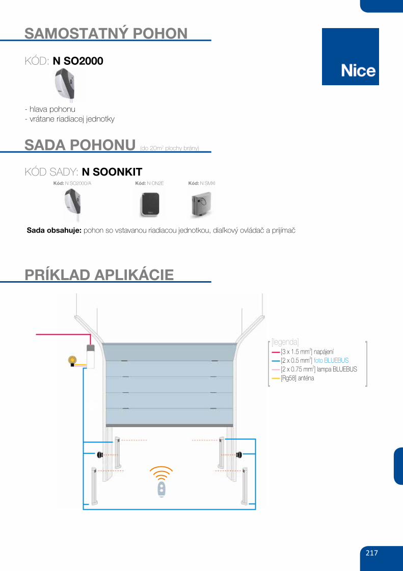
217
SAMOSTATNÝ POHON
- hlava pohonu- vrátane riadiacej jednotky
SADA POHONU (do 20m2 plochy brány)
KÓD SADY: N SOONKIT
Sada obsahuje: pohon so vstavanou riadiacou jednotkou, diaľkový ovládač a prijímač
Kód: N ON2E Kód: N SMXI
KÓD: N SO2000
Kód: N SO2000/A
MLBlampa sygnalizacyjna BLUEBUS
12V z wbudowaną anteną 433.92 MHz
110,00
135,30 brutto
LUCYBlampa sygnalizacyjna BLUEBUS
12V z wbudowaną anteną 433.92 MHz
100,00
123,00 brutto
AKCESORIA
FT210B MOFB PS124fotokomórki (para-bez baterii),
BLUEBUS nastawne z kątem 210°,
zasięg 15 m
fotokomórki (para) BLUEBUS,
zasięg 15-30 m
akumulator 24V 1.2 Ah
z wbudowaną kartą ładowania
350,00
430,50 brutto
190,00
233,70 brutto
290,00
356,70 brutto
[3 x 1.5 mm ]2
napájení
[2 x 0.5 mm ]2
foto BLUEBUS
[2 x 0.75 mm ] lampa BLUEBUS2
[Rg58] ant naé
[legenda]
cena netto cena brutto
SOON
ERA FLOR
SOON
SMILO
Zestaw do bram segmentowych: siłownik SO2000 z wbudowaną centralą BLUEBUS, radioodbiornik SMXI, 1 pilot dwukanałowy FLO2RE,
fotokomórki MOFBZestaw do bram segmentowych: siłownik SO2000 z wbudowaną centralą BLUEBUS, radioodbiornik SMXIS, 2 piloty dwukanałowe SM2,
fotokomórki MOFB
PRZYKŁADOWY ZESTAW
2 730,602 220,00
2 755,202 240,00
|87AUTOMATYKA DO BRAM GARAŻOWYCH
PRÍKLAD APLIKÁCIE
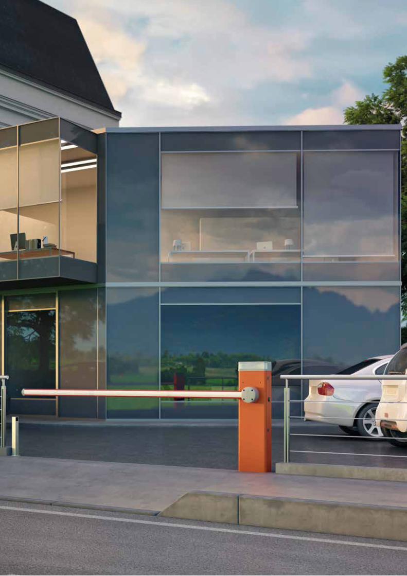
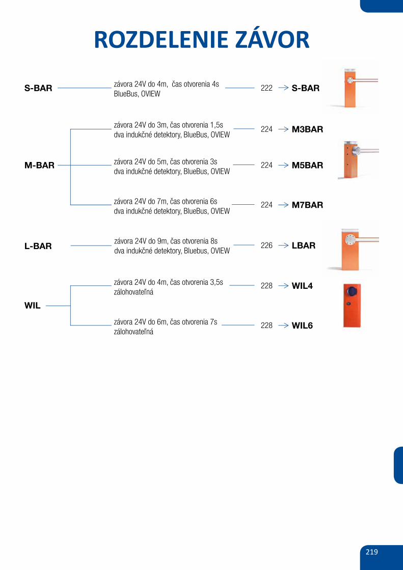
219
ROZDELENIE ZÁVOR
S-BAR závora 24V do 4m, čas otvorenia 4sBlueBus, OVIEW
S-BAR
L-BAR
M-BAR
222
závora 24V do 3m, čas otvorenia 1,5sdva indukčné detektory, BlueBus, OVIEW
224 M3BAR
závora 24V do 5m, čas otvorenia 3sdva indukčné detektory, BlueBus, OVIEW
224 M5BAR
závora 24V do 7m, čas otvorenia 6sdva indukčné detektory, BlueBus, OVIEW
224 M7BAR
závora 24V do 9m, čas otvorenia 8sdva indukčné detektory, Bluebus, OVIEW
226 LBAR
WIL
závora 24V do 4m, čas otvorenia 3,5szálohovateľná
228 WIL4
závora 24V do 6m, čas otvorenia 7szálohovateľná
228 WIL6
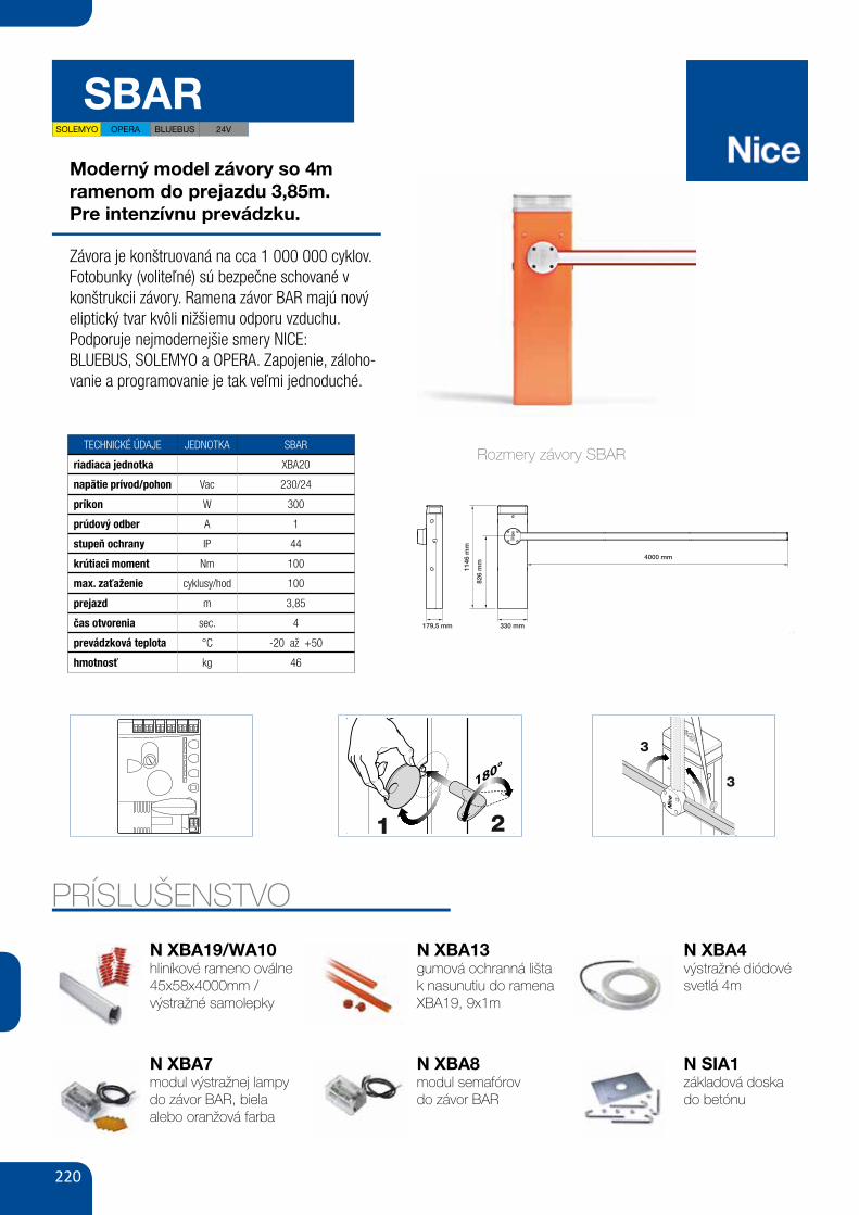
220
SBAR
Moderný model závory so 4m ramenom do prejazdu 3,85m.Pre intenzívnu prevádzku.
Závora je konštruovaná na cca 1 000 000 cyklov.Fotobunky (voliteľné) sú bezpečne schované v konštrukcii závory. Ramena závor BAR majú nový eliptický tvar kvôli nižšiemu odporu vzduchu.Podporuje nejmodernejšie smery NICE:BLUEBUS, SOLEMYO a OPERA. Zapojenie, záloho-vanie a programovanie je tak veľmi jednoduché.
TECHNICKÉ ÚDAJE JEDNOTKA SBAR
riadiaca jednotka XBA20
napätie prívod/pohon Vac 230/24
príkon W 300
prúdový odber A 1
stupeň ochrany IP 44
krútiaci moment Nm 100
max. zaťaženie cyklusy/hod 100
prejazd m 3,85
čas otvorenia sec. 4
prevádzková teplota °C -20 až +50
hmotnosť kg 46
PRÍSLUŠENSTVOI
2
1
A
B
CB
179,5 mm 330 mm
1146
mm
826
mm
4000 mm
3
b
a
de
f
g
h
c
Rozmery závory SBAR
N XBA19/WA10hliníkové rameno oválne 45x58x4000mm /výstražné samolepky
N XBA7modul výstražnej lampy do závor BAR, biela alebo oranžová farba
N XBA13gumová ochranná lišta k nasunutiu do ramena XBA19, 9x1m
N XBA8modul semafórovdo závor BAR
N XBA4výstražné diódové svetlá 4m
N SIA1základová doskado betónu
EN
English – 17
Operation manual(to be given to the final user of SBAR)
Warnings
1 - Children: An automation system guarantees a high level ofsafety, using its detection systems to prevent movement in the pres-ence of persons or objects, and ensuring constantly foreseeable andsafe activation. Nonetheless, it is advisable to ensure that children donot play in the vicinity of the automation. To prevent the risk of acci-dental activation, do not leave the remote controls within the reach ofchildren. this is not a toy!
2 - This product is not designed to be used by persons (includingchildren) whose physical, sensorial or mental capacities are reduced,or with lack of experience or skill, unless suitable instructions regard-ing use of the product have been provided by a person responsiblefor safety or under supervision of the latter.
3 - Malfunctions: if the automation is seen to perform abnormally,disconnect the electrical power supply from the system and manuallyrelease the gearmotor. Never attempt to perform repairs; contact yourlocal installer for assistance. In the meantime the system can beused as a manual access point, after releasing the gearmotor asdescribed be low in this document. In the event of breakage or apower failure, while waiting for the installer or the electricalpower supply to return, if the buffer battery is not fitted, theautomation can still be used. Manually release the gearmotor (seestep 9 - Gearmotor manual releasing and locking) and move the polemanually as required.
4 - Safety devices disabled: the barrier can be operated evenwhen the safety device on the barrier do not work correctly.- Activate the barrier command (with the transmitter or key-operat-
ed selector switch, etc.); if all is in working order, the pole opens orcloses normally; otherwise the flashing light emits a number offlashes and the manoeuvre is not started (the number of flashesdepends on the reason for which the manoeuvre does not start).
- In this case, the user must press and hold the command withinthree seconds.
- After approx. 2 seconds the barrier will start to operate in “hold-to-run” mode, i.e. the pole will continue to move while the commandis activated; THE POLE STOPS AS SOON AS THE COMMAND ISRELEASED.
If the safety devices are out of service, the automation must berepaired as soon as possible.
5 - Even if you possess the skills, never modify the system or pro-gramming and setting parameters of the automation: this is theresponsibility of the installer.
6 - Testing, periodic maintenance and any repairs must be docu-mented by the person performing the operations and the relevantdocuments must be kept by the system owner. The only operationsthat can be performed by the user periodically are to clean the pho-tocell lenses and the automation. To prevent anyone from activatingthe barrier release the automation system before proceeding with theoperations (as described below). Use a slightly damp cloth to clean.
7 - Disposal: At the end of the automation’s lifetime, ensure that itis disposed by qualified personnel and that the materials are recycledor scrapped according to current local standards.
9 - Gearmotor manual release and locking: The gearmotor isequipped with a mechanical system that enables manual openingand closing of the pole. These operations are required in the event ofa power failure or malfunctions.
Before using the automation for the first time, ask the installer to explain the origin of residual risks and devote a few minutes to reading this userinstruction and warning manual given to you by the installer. Keep the manual for reference when in doubt and pass it on to new owners of theautomation.CAUTION! – Your automation is a machine that performs your commands faithfully; negligent or improper use may constitute a hazard:– Never activate automation controls if persons, animals or objects are present in the operating range.– Never touch parts of the automation while the pole is moving!– Transit is only permitted if the pole is completely open and stationary!
180°
A
1
3
3
2
IMPORTANT!
– The gearmotor release and locking operations must be per-formed only when the pole is horizontal and stationary.
– The gearmotor can be released manually on both sides of thebarrier.
01. Unscrew the key cover (Fig. A - 1); 02. Insert the key supplied and turn through 180° (Fig. A - 2);03. Move the pole as required (Fig. A - 3);04. To lock the gearmotor, rotate the key through a further 180°.
SOLEMYO OPERA BLUEBUS 24V
VIII
MOTB/MOFBOPEN CLOSE
TX RX
NC NCNO NOC C
27
Op
en
StopSet
Close
Fuse 1AT
L2L3L4L5L6L7L8
28 29
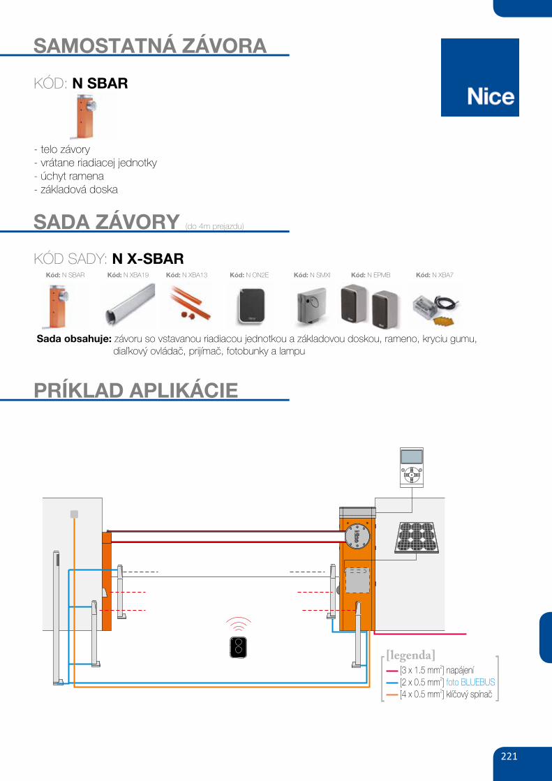
221
SAMOSTATNÁ ZÁVORA
- telo závory- vrátane riadiacej jednotky- úchyt ramena- základová doska
KÓD: N SBAR
SADA ZÁVORY (do 4m prejazdu)
KÓD SADY: N X-SBAR
Sada obsahuje: závoru so vstavanou riadiacou jednotkou a základovou doskou, rameno, kryciu gumu, diaľkový ovládač, prijímač, fotobunky a lampu
Kód: N SMXI Kód: N EPMBKód: N XBA13Kód: N XBA19Kód: N SBAR Kód: N ON2E Kód: N XBA7
XBA4diodowe światła
ostrzegawcze 4 m290,00
356,70 brutto
180,00
221,40 brutto
PS124akumulator 24V 1.2 Ah
z wbudowaną kartą ładowania
XBA19
XBA13 XBA7 SIA1
WA11ramię aluminiowe,
owalne, 45x58x4000 mm
listwy ochronne, gumowe,
czerwone na ramię XBA 9x1 m
moduł lampy sygnalizacyjnej
kolor biały lub pomarańczowy
do szlabanów BAR
płyta montażowa z kotwami
podpora ramienia stała,
regulowana wysokość150,00
184,50 brutto
120,00
147,60 brutto
175,00
215,25 brutto
200,00
246,00 brutto
250,00
307,50 brutto
WA10
80,00
98,40 brutto
nalepki ostrzegawcze
na ramię szlabanu (24 szt.)
AKCESORIA
|109SZLABANY
[2 x 0.5 mm ]2
foto BLUEBUS
[4 x 0.5 mm ]2
klíčový spínač
[3 x 1.5 mm ]2
napájení
[legenda]
XBA8moduł semaforów do szlabanów
BAR
250,00
307,50 brutto
POZOSTAŁE AKCESORIA STR. 96-105
MOFBfotokomórki (para) BLUEBUS
zasięg 15-30 m
190,00
233,70 brutto
PRÍKLAD APLIKÁCIE
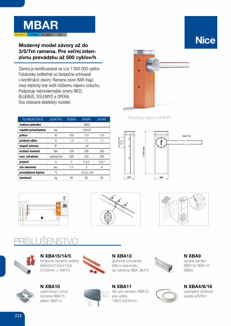
222
MBAR
Moderný model závory až do3/5/7m ramena. Pre veľmi inten-zívnu prevádzku až 500 cyklov/h
Závora je konštruovaná na cca 1 000 000 cyklov.Fotobunky (voliteľné) sú bezpečne schovanév konštrukcii závory. Ramena závor BAR majúnový eliptický tvar kvôli nižšiemu odporu vzduchu.Podporuje nejmodernejšie smery NICE:BLUEBUS, SOLEMYO a OPERA.Dva vstavané detektory vozidiel.
TECHNICKÉ ÚDAJE JEDNOTKA M3BAR M5BAR M7BAR
riadiaca jednotka XBA3
napätie prívod/pohon Vac 230/24
príkon W 150 110 110
prúdový odber A 1,3 1,1 1,1
stupeň ochrany IP 44
krútiaci moment Nm 100 200 300
max. zaťaženie cyklusy/hod 500 350 200
prejezd m 3 3,4,5 5,6,7
čas otvorenia sec. 1,5 3 6
prevádzková teplota °C -20 až +50
hmotnosť kg 80 80 85
WYMIARY
AKCESORIA
1.21
5 m
m
400
max 7 m
XBA5ramię aluminiowe,
owalne, 69x92x5150 mm80,00
98,40 brutto
250,00
307,50 brutto
XBA9łącznik do ramion
XBA15/XBA14/XBA5
XBA15
XBA4 XBA6 XBA18 XBA10 XBA11
XBA14ramię aluminiowe,
owalne, 69x92x3150 mm
diodowe światła
ostrzegawcze, 4 m
diodowe światła
ostrzegawcze, 6 m
diodowe światła
ostrzegawcze, 8 m
uchwyt przegubowy
dla ramion 3 lub 4 m
przegub dla ramion XBA15
(od 1950 do 2400 mm)
wys. po podniesieniu
ramię aluminiowe,
owalne, 69x92x4150 mm200,00
246,00 brutto
180,00
221,40 brutto
200,00
246,00 brutto
220,00
270,60 brutto
370,00
455,10 brutto
480,00
590,40 brutto
220,00
270,60 brutto
XBA13
120,00
147,60 brutto
listwy ochronne, gumowe,
czerwone na ramię XBA, 9x1 m
WA12
PS224
WA11
WA13
XBA8
XBA16
XBA7 WA10podpora ramienia
ruchoma
akumulator 24V 7.2 Ah
z wbudowaną kartą ładowania
podpora ramienia stała,
regulowana wysokość
listwy aluminiowe, zabezpieczające,
pod ramię płaskie, w odc. 2 m
moduł semaforów do szlabanów
BAR
płyta montażowa
z kotwami
moduł lampy sygnalizacyjnej
do szlabanów BAR
nalepki ostrzegawcze
na ramię szlabanu (24 szt.)250,00
307,50 brutto
460,00
565,80 brutto
250,00
307,50 brutto
320,00
393,60 brutto
250,00
307,50 brutto
200,00
246,00 brutto
175,00
215,25 brutto
80,00
98,40 brutto
|111SZLABANY
POZOSTAŁE AKCESORIA STR. 96-105
MOFBfotokomórki (para) BLUEBUS
zasięg 15-30 m190,00
233,70 brutto
PRÍSLUŠENSTVO
AKCESORIA
SCHEMAT INSTALACJI
1.21
5 m
m
299 400
max 7 m
XBA5ramię aluminiowe,
owalne, 69x92x5150 mm80,00
98,40 brutto
250,00
307,50 brutto
XBA9łącznik do ramion
XBA15/XBA14/XBA5
XBA15
XBA4 XBA6 XBA18 XBA10 XBA11
XBA14ramię aluminiowe,
owalne, 69x92x3150 mm
diodowe światła
ostrzegawcze, 4 m
diodowe światła
ostrzegawcze, 6 m
diodowe światła
ostrzegawcze, 8 m
uchwyt przegubowy
dla ramion 3 lub 4 m
przegub dla ramion XBA15
(od 1950 do 2400 mm)
wys. po podniesieniu
ramię aluminiowe,
owalne, 69x92x4150 mm200,00
246,00 brutto
180,00
221,40 brutto
200,00
246,00 brutto
220,00
270,60 brutto
370,00
455,10 brutto
480,00
590,40 brutto
220,00
270,60 brutto
XBA13
120,00
147,60 brutto
listwy ochronne, gumowe,
czerwone na ramię XBA, 9x1 m
WA12
PS224
WA11
WA13
XBA8
XBA16
XBA7 WA10podpora ramienia
ruchoma
akumulator 24V 7.2 Ah
z wbudowaną kartą ładowania
podpora ramienia stała,
regulowana wysokość
listwy aluminiowe, zabezpieczające,
pod ramię płaskie, w odc. 2 m
moduł semaforów do szlabanów
BAR
płyta montażowa
z kotwami
moduł lampy sygnalizacyjnej
do szlabanów BAR
nalepki ostrzegawcze
na ramię szlabanu (24 szt.)250,00
307,50 brutto
460,00
565,80 brutto
250,00
307,50 brutto
320,00
393,60 brutto
250,00
307,50 brutto
200,00
246,00 brutto
175,00
215,25 brutto
80,00
98,40 brutto
Przełącznik
kluczykowy
lub cyfrowy
Fotokomórki
na słupku
Fotokomórki
naścienne
POZOSTAŁE AKCESORIA STR. 96-105
MOFBfotokomórki (para) BLUEBUS
zasięg 15-30 m190,00
233,70 brutto
Rozmery závory M-BAR
XI
33
34
30
31
32
c
a
b
c
a
b
N XBA10vylamovací úchytramena XBA15alebo XBA14
N XBA15/14/5hliníkové rameno oválne 69x92x3150/4150/ 5150mm + WA10
N XBA13gumová ochrannálišta k nasunutiudo ramena XBA, 9x1m
N XBA11kĺb pre rameno XBA15 pre výšku1950-2400mm
N XBA9spojka ramien XBA15/ XBA14/ XBA5
N XBA4/6/18výstražné diódové svetlá 4/6/8m
XVI
51
52
a
b
SOLEMYO OPERA BLUEBUS 24V
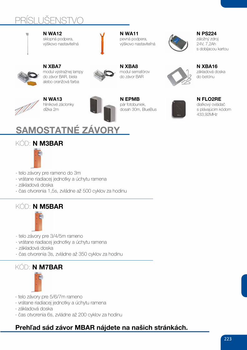
223
SAMOSTATNÉ ZÁVORY
- telo závory pre rameno do 3m- vrátane riadiacej jednotky a úchytu ramena- základová doska- čas otvorenia 1,5s, zvládne až 500 cyklov za hodinu
KÓD: N M3BAR
PRÍSLUŠENSTVO
N XBA7modul výstražnej lampy do závor BAR, biela alebo oranžová farba
N WA12sklopná podpera,výškovo nastaviteľná
N WA11pevná podpera,výškovo nastaviteľná
N XBA8modul semafórovdo závor BAR
N PS224záložný zdroj24V, 7,2Ahs dobíjacou kartou
N XBA16základová doskado betónu
N WA13hliníkové záclonkydĺžka 2m
N EPMBpár fotobuniek,dosah 30m, BlueBus
N FLO2REdiaľkový ovládačs plávajúcim kódom 433,92MHz
- telo závory pre 3/4/5m rameno- vrátane riadiacej jednotky a úchytu ramena- základová doska- čas otvorenia 3s, zvládne až 350 cyklov za hodinu
KÓD: N M5BAR
- telo závory pre 5/6/7m rameno- vrátane riadiacej jednotky a úchytu ramena- základová doska- čas otvorenia 6s, zvládne až 200 cyklov za hodinu
KÓD: N M7BAR
Prehľad sád závor MBAR nájdete na našich stránkách.
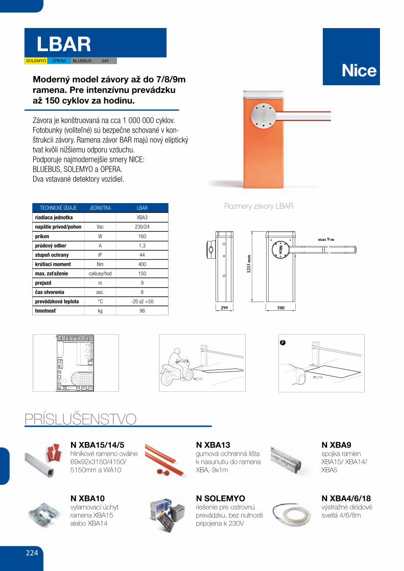
224
LBAR
Moderný model závory až do 7/8/9m ramena. Pre intenzívnu prevádzkuaž 150 cyklov za hodinu.
Závora je konštruovaná na cca 1 000 000 cyklov.Fotobunky (voliteľné) sú bezpečne schované v kon-štrukcii závory. Ramena závor BAR majú nový eliptický tvat kvôli nižšiemu odporu vzduchu.Podporuje najmodernejšie smery NICE:BLUEBUS, SOLEMYO a OPERA.Dva vstavané detektory vozidiel.
TECHNICKÉ ÚDAJE JEDNOTKA LBAR
riadiaca jednotka XBA3
napätie prívod/pohon Vac 230/24
príkon W 160
prúdový odber A 1,3
stupeň ochrany IP 44
krútiaci moment Nm 400
max. zaťaženie cyklusy/hod 150
prejazd m 9
čas otvorenia sec. 8
prevádzková teplota °C -20 až +50
hmotnosť kg 98
PRÍSLUŠENSTVO
SCHEMAT INSTALACJI
AKCESORIA
XBA5ramię aluminiowe,
owalne, 69x92x5150 mm80,00
98,40 brutto
250,00
307,50 brutto
XBA9łącznik do ramion
XBA15/XBA14/XBA5
XBA15
XBA4 XBA6 XBA18 XBA10 WA10
XBA14ramię aluminiowe,
owalne, 69x92x3150 mm
diodowe światła
ostrzegawcze, 4 m
diodowe światła
ostrzegawcze, 6 m
diodowe światła
ostrzegawcze, 8 m
uchwyt przegubowy
dla ramion 3 lub 4 m
nalepki ostrzegawcze
na ramię szlabanu (24 szt.)
ramię aluminiowe,
owalne, 69x92x4150 mm200,00
246,00 brutto
180,00
221,40 brutto
200,00
246,00 brutto
220,00
270,60 brutto
370,00
455,10 brutto
80,00
98,40 brutto
220,00
270,60 brutto
XBA13
120,00
147,60 brutto
listwy ochronne, gumowe,
czerwone na ramię XBA, 9x1 m
WA12 WA11 XBA8 XBA7podpora ramienia
ruchoma
podpora ramienia stała,
regulowana wysokość
moduł semaforów do szlabanów
BAR
moduł lampy sygnalizacyjnej
do szlabanów BAR250,00
307,50 brutto
250,00
307,50 brutto
250,00
307,50 brutto
175,00
215,25 brutto
1215
mm
299 500
max 9 mPrzełącznik
kluczykowy
lub cyfrowy
Fotokomórki
na słupku
Fotokomórki
naścienne
POZOSTAŁE AKCESORIA STR. 96-105
PS224akumulator 24V 7.2 Ah
z wbudowaną kartą ładowania460,00
565,80 brutto
MOFB SOLEMYO (SYKCE)fotokomórki (para) BLUEBUS
zasięg 15-30 m
zestaw zasilania słonecznego
190,00
233,70 brutto
1 350,00
1 660,50 brutto
Rozmery závory LBAREN
English – 17
G
approximately 0,8 m
Direction of travel
0,2 m
Route
45°
01. After determining the size of the loop, dig a groove in the floor of a width = 8 mm and a depth = 30-50 mm (fig. H);
02. Clean the groove and insert the loop, trying to compact it in a way to avoid it moving;
03. Carry out the number of turns of the loop depending on the perimeter, as indicated in Table 17: use a 1 .5 mm2 unipolar isolated copper cable (fig. H);
04. Before sealing the groove, check that the value of the inductive loop is between 100 and 400 uH or, through the Oview programmer, check that the value of the measured frequency (Parameter “Loop Frequency”) is between 30 and100 KHz;
05. Cover the loop with sand to protect it and then seal the groove with bitu-men or resin for outdoor use (fig. H) . Important! – The temperature of the sealant must not exceed the maximum temperature admitted for the isola-tion of the cable, otherwise a loss in isolation towards the earth may occur .
06. The electric cables must be connected to the Loop1 (fig. I) and Loop2
(fig. L) terminals . The Loop2 terminal presents 2 connection possibilities (fig. L); based on the type of connection used, it varies the working fre-quency of the loop .
Important! – If Loop1 is positioned near Loop2 and both work at the same frequency (or almost), interference could be generated; in this case, it is necessary to change the connection to Loop2 terminal .
TABLE 16
1loop
relay
loop
relay
2
loop
relay
3loop
relay
4
loop
relay
5
TABLE 17Perimeter of the loop Number of turns to be carried out
2 – 4 m 6
4 – 7 m 5
7 – 12 m 4
more than 12 m 3
Note – If in the loop positioning place, below the floor, there are some metal reinforcements, the inductivity of the loop is reduced . In this case, it is necessary to add 2 turns to the twisting of the cable
TABLE 15Function Values Default
Loop 1 sensitivity 10 – 100% 90%Loop 2 sensitivity 10 – 100% 90%Loop power supply on – off onLoop 1 active on – off onLoop 2 active on – off onLoop 1 operating mode 1 – 5 1Loop 2 operating mode 1 – 5 1Loop 1 permanence time 2 – 20 = always 20 = alwaysLoop 2 permanence time 2 – 20 = always 20 = alwaysOutput function 1, 2, 3: Active out (1,2,3) for loop 1 selectable offOutput function 1, 2, 3:Active out (1,2,3) for loop 2 selectable offCalibration [also carried out upon start-up] on – off Loop 1 activation mode*: 1 – 5 1Loop 1 time 0 – 25 s 2sLoop 2 activation mode*: 1 – 5 1Loop 2 time 0 – 25 s 2sLoop 1 frequency display 0 - 127000 -Loop 2 frequency display 0 - 127000 -
N XBA10vylamovací úchytramena XBA15alebo XBA14
N XBA15/14/5hliníkové rameno oválne 69x92x3150/4150/ 5150mm a WA10
N XBA13gumová ochranná lišta k nasunutiu do ramena XBA, 9x1m
N SOLEMYOriešenie pre ostrovnú prevádzku, bez nutnosti pripojena k 230V
N XBA9spojka ramien XBA15/ XBA14/ XBA5
N XBA4/6/18výstražné diódové svetlá 4/6/8m
EN
18 – English
7.6 - Master - Slave modeThis operating mode is used if it is necessary to automate 2 counterposed barriers which perform synchronised movements . In this mode, a barrier works as Master and commands the manoeuvres, while the second works as Slave and carries out the commands sent from the Master barrier; by default all the barriers are set as Master .To configure the barrier as Slave it is necessary to activate the level 1 function “Slave Mode” (see Table 7) .The connection between Master and Slave takes place through the BusT4 with the dedicated Master/Slave connector .
Important! – Should the Oview programmer be used, it is necessary to modify the parameter “Griup” or “Address” of one of the 2 barriers. This is to avoid the simultaneous communication of the 2 control units with the Oview programmer.7.6.1 - Installation and electrical connectionsWarnings• All the devices, including the radio receiver, must be connected on the Master
barrier;• If the buffer battery is used, each barrier must have its own;• In the Slave barrier it is possible to carry out the following connections:
- its own flashing light (Flash) - its own Pole Open Indicator (S .C .A .) - pole lights - its own sensitive edge (Stop) - its own command device (P .P .), which commands the total opening of
the Slave pole only - the Open and Close inputs are not used - the Loop1 and Loop2 inputs programmed with “Open” mode - the receiving radio
To install 2 barriers and program them with “Master - Slave” mode, proceed as follows:01. Install the 2 barriers (fig. M) . It is not important which of the two works as Master or Slave; it is neces-
sary to assess the convenience to create the electrical connections and that the “Step-Step” command that will carry out the Slave barrier will pro-vide the total open of the Slave pole only;
02. Connect the two control units one to the other through the Master/Slave connector (fig. 54), respecting the polarity indicated;
03. At this point, carry out the other electrical connections (fig. 54), referring to the indications contained in chapter 4 - Electrical connections;
IF
approximately 0,35 m
Direction of travel
Route
1 m
H 5 mm - 8 mm
SealantGrooveString
Loop(the cable must be inserted in the groove)
Connection (twisted cable)
Groove5 - 8 mm
Earth
Twisted cable
30 mm -50 mm
L
LOOP1 LOOP2 LOOP1 LOOP2
58 GATE&DOOR 2013
≥ 130
≥ 300
B ≥ 710 mmA ≥ 450
B ≤
450
A ≤
350
hyPPO 7000
800
700
600
500
400
300
2002 2,5 3
HY7005
HY7005 / HY7024
165350 mm24
2
9015
2
230V24VbLuEbusOPERAsOLEmyO
hy7024 hy7005
- 23024 -5 1.2
120 250
2 1.7250 40080 30
43-20 ÷ +50
350x165x242 h13
For swing gates with leaves up to 3 m, also ideal for large pillars. Electromechanical gear motor, surface mounted, also in 24 Vdc version with magnetic encoder, with articulated arm.
Single model for right and left leaves. Two irreversible versions, with 230 Vac (HY7005) and 24 Vdc (HY7024) power supplies with magnetic encoder.
Fewer connections mean quicker installation.
Pre-wired, incorporated double limit-switch both during opening and closing (HY7005).
mAx
. GAT
E W
EIGh
T (k
G)
mAx. GATE LENGTh (m)
N.B. The above values are valid if the motor is used with standard accessories. The shape, the height of the gate and the weather conditions can considerably reduce the values shown in the graph to the side. Use in windy areas 230 Vac models.
CODE DESCRIPTION PACK/PALLET
hy7024 IRREVERSIBLE, 24 Vdc, WITH MAGNETIC ENCODER, WITH SHEAR-PROOF ARTICULATED ARM, GALVANIZED AND PAINTED
16
hy7005 IRREVERSIBLE, 230 Vac, WITH STURDY ARTICULATED SHEAR-PROOF ARM, GALVANIZED AND PAINTED, WITH LIMIT SWITCH ON OPENING AND CLOSING
16
Easy and quick to install: thanks to fewer connections and nothing welded to the gates.
Long-lasting: solid metal mechanics.
Compact: shockproof bodywork with no sharp corners.
Recommended control units: Mindy A6F, A60, A700F; for HY7024 Moonclever MC824H.
24 Vdc version with magnetic encoder. Perfect for intensive use, compatible with the control unit Moonclever MC824H: • simple programming, by means of a single key; • self-learning of opening and closing limit positions; • automatic fault diagnostics; • programming of pause time; • pedestrian pass door; • deceleration on opening and closing; • obstacle detection with dual technology; • operation in event of power failure by means of optional rechargeable batteries (PS324); • provision for connection of latest generation resistive sensitive edges.
TEChNICAL sPECIFICATIONsCODEELECTRICAL DATAPOWER SUPPLY (Vac 50 Hz)*POWER SUPPLY (Vdc)ABSORPTION (A)POWER (W)PERFORmANCE DATASPEED (rpm)TORqUE (Nm)WORK CYCLE (%)DImENsIONAL AND GENERAL DATAPROTECTION LEVEL (IP)WORKING TEMP. (°C MIN/MAx)DIMENSIONS (mm)WEIGHT (kg)
*60 Hz version available on request.
A Standard armb Arm with accessory HYA12
uTILIsATION LImITs DImENsIONs
STURDY, ANTI-SHEARING ARM, GALVANISED AND PAINTED; STRENGTHENED IN THOSE AREAS SUBjECTED TO GREATER MECHANICAL STRESS
DIE-CAST, ALUMINIUM, KEY-OPERATED UNLOCK SYSTEM, COMPLETE WITH PROTECTED KEY. DESIGNED TO ACCOMMODATE ExTERNAL RELEASE, TOO
SOLEMYO OPERA BLUEBUS 24V
XIII
L N4039
NC NCNO NOC C
MOTB/MOFBOPEN CLOSE
TX RX24V 4W
LIGHTFLASHSCA BLUEBUS STOP OPEN CLOSEP.P.LIGHTFLASHSCA BLUEBUS STOP OPEN CLOSEP.P.
LOOP2LOOP1
41
IN 1IN 2
IN 3
LOOP 2MASTERSLAVE
LOOP 1
OUT 3OUT 2
OUT 1
c
a
b
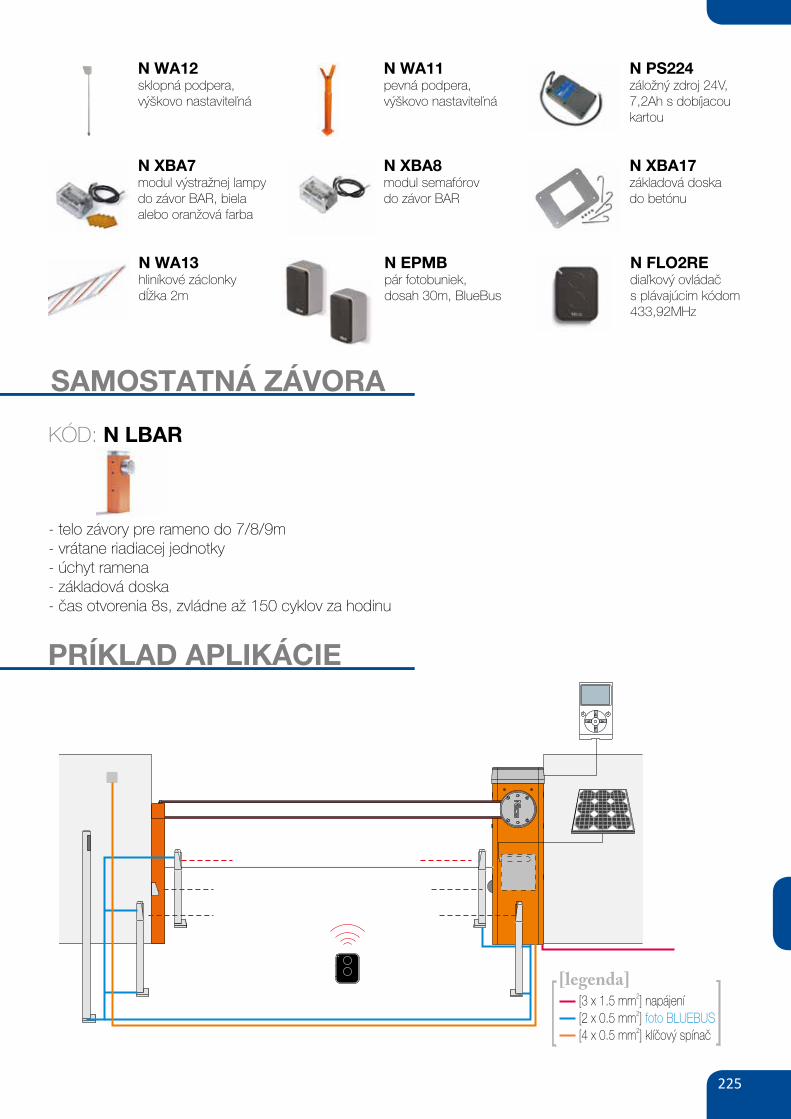
225
XBA4diodowe światła
ostrzegawcze 4 m290,00
356,70 brutto
180,00
221,40 brutto
PS124akumulator 24V 1.2 Ah
z wbudowaną kartą ładowania
XBA19
XBA13 XBA7 SIA1
WA11ramię aluminiowe,
owalne, 45x58x4000 mm
listwy ochronne, gumowe,
czerwone na ramię XBA 9x1 m
moduł lampy sygnalizacyjnej
kolor biały lub pomarańczowy
do szlabanów BAR
płyta montażowa z kotwami
podpora ramienia stała,
regulowana wysokość150,00
184,50 brutto
120,00
147,60 brutto
175,00
215,25 brutto
200,00
246,00 brutto
250,00
307,50 brutto
WA10
80,00
98,40 brutto
nalepki ostrzegawcze
na ramię szlabanu (24 szt.)
AKCESORIA
|109SZLABANY
[2 x 0.5 mm ]2
foto BLUEBUS
[4 x 0.5 mm ]2
klíčový spínač
[3 x 1.5 mm ]2
napájení
[legenda]
XBA8moduł semaforów do szlabanów
BAR
250,00
307,50 brutto
POZOSTAŁE AKCESORIA STR. 96-105
MOFBfotokomórki (para) BLUEBUS
zasięg 15-30 m
190,00
233,70 brutto
SAMOSTATNÁ ZÁVORA
- telo závory pre rameno do 7/8/9m- vrátane riadiacej jednotky- úchyt ramena- základová doska- čas otvorenia 8s, zvládne až 150 cyklov za hodinu
KÓD: N LBAR
N XBA7modul výstražnej lampy do závor BAR, biela alebo oranžová farba
N WA12sklopná podpera,výškovo nastaviteľná
N WA11pevná podpera,výškovo nastaviteľná
N XBA8modul semafórovdo závor BAR
N PS224záložný zdroj 24V, 7,2Ah s dobíjacou kartou
N XBA17základová doskado betónu
N WA13hliníkové záclonkydĺžka 2m
N EPMBpár fotobuniek,dosah 30m, BlueBus
N FLO2REdiaľkový ovládačs plávajúcim kódom 433,92MHz
PRÍKLAD APLIKÁCIE
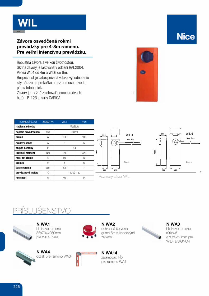
226
WIL
Závora osvedčená rokmiprevádzky pre 4-8m rameno.Pre veľmi intenzívnu prevádzku.
Robustná závora s veľkou životnosťou.Skriňa závory je lakovaná v odtieni RAL2004.Verzia WIL4 do 4m a WIL6 do 6m.Bezpečnosť je zabezpečená vďaka vyhodnoteniu sily nárazu na prekážku a tiež pomocou dvoch párov fotobuniek.Závory je možné zálohovať pomocou dvochbatérií B-12B a karty CARICA.
TECHNICKÉ ÚDAJE JEDNOTKA WIL4 WIL6
riadiaca jednotka WA20/A
napätie prívod/pohon Vac 230/24
príkon W 180 100
prúdový odber A 8 5
stupeň ochrany IP 44
krútiacií moment Nm 150 220
max. zaťaženie % 80 80
prejazd m 4 6
čas otvorenia sec. 3,5 7
prevádzková teplota °C -20 až +50
hmotnosť kg 46 54
PRÍSLUŠENSTVO
N WA4držiak pre rameno WA3
N WA1hliníkové rameno 36x73x4250mmpre WIL4, biele
N WA2ochranná červená guma 8m s koncovými zátkami
N WA14zalamovací kĺbpre rameno WA1
N WA3hliníkové rameno rúrkovéø70x4250mm pre WIL4 a SIGNO4
24V
WIL
3
1) WIL2) Colonnina per selettore achiave.3) Selettore a chiave.4) Tastiera digitale.5) Colonnina per fotocellula.6) Fotocellula.7) Costa pneumatica ogomma rossa.8) Gomma protettiva rossa.9) Asta in alluminio10) Luci lampeggianti.11) Striscie rosse catari-frangenti.12) Lampeggiatore.13) Antenna.
1) WIL2) Column for the keyselector3) Key seloctor4) Digital keypad5) Column for the photocell6) Photocell7) Pneumatic edge or redrubber8) Protective red rubberprofile9) Aluminium bar10) Flashing lights11) Red reflector strips12) Flashing light13) Antenna
1)WIL2) Colonne pour sélecteur à clé3) Sélecteur à clé4) Tableau de commande digital5) Colonne pour cellulephotoélectrique6) Cellule photoélectrique7) Barre palpeuse ou profilcaoutchouc rouge8) Profil de protection encaoutchouc rouge9) Barre en aluminium10) Lumières clignotantes11) Bandes rougescatadioptriques12) Clignotant13) Antenne
1) WIL2) Säule fürSchiüsselwähischalter.3) Schlüsselwähischalter.4) Digitaltastatur.5) Säule für Photozelle.6) Photozelle.7) PneumatischeSicherheitsleiste oderroter Gummi.8) Roter Schutzgummi.9) Aluminiumstange.10) Blinklichter.11) Rote, rückstrahlendeStreifen.12) Blinker13) Antenne.
1) WIL2) Columna para el selectorde llave3) Selector de llave4) Teclado digital5) Columna para fotocélula6) Fotocélula7) Borde neumático y perfilde caucho rojo 8) Perfil de caucho rojo deprotección9) Barrera de aluminio10) Luces intermitentes11) Bandas rojasretrorreflociantes12) Luz intermitente13) Antena.
DIMENSIONI D' INGOMBRO - DIMENSIONS - DIMENSIONS D'ENCOMBREMENT - RAUMBEDARF - DIMENSIONES
QUADRO D’INSIEME - OVERALL PICTURE - CADRE GÉNÉRAL - ÜBERSICHTZEICHNUNG - ESQUEMA DE CONJUNTO
GBI F D E
LIMITI DI IMPIEGO
Applicando all’asta tutti gliaccessori opzionali, limitar-si ad una lunghezza max. dimt. 5 per WIL 6 e di mt. 3,5per WIL 4.
LIMITS OF USE
When installing all theoptional accessories on therod, envisage a max. rodlenght of 5 m. for WIL 6 and3,5 m for WIL 4.
LIMITES D’UTILISATION
En applicant à la lisse tousles accessoires en option,se limiter à une longueurmaximum de 5 m pour WIL6 et de 3,5 m pour WIL 4.
EINSATZGRENZEN
Bei der Anbringung allerSonderzubehörteile an derStange muss man sich beiWIL 6 auf eine Höchstlängevon 5 m und bei WIL 4 aufeine Höchstlänge von 3,5 mbeschränken.
LÍMITES DE EMPLEO
Si aplica a la barrera todoslos accesorios optionales,la longitud máxima debeser de 5 m para WIL 6 y de3,5 m para WIL 4.
GBI F D E
4
3
2
6
5
6
5
2 x 1
8 9
7
10
11
4 x 1
6
5
16
5
12 13
3 x 1,5
2 x
1,5
+ R
G 5
8
WIL 4Max 4 m.
WIL 6Max 6 m.
290 290
220 320320 420
1000
1050
3 .giF2 .giF
Rozmery závor WIL
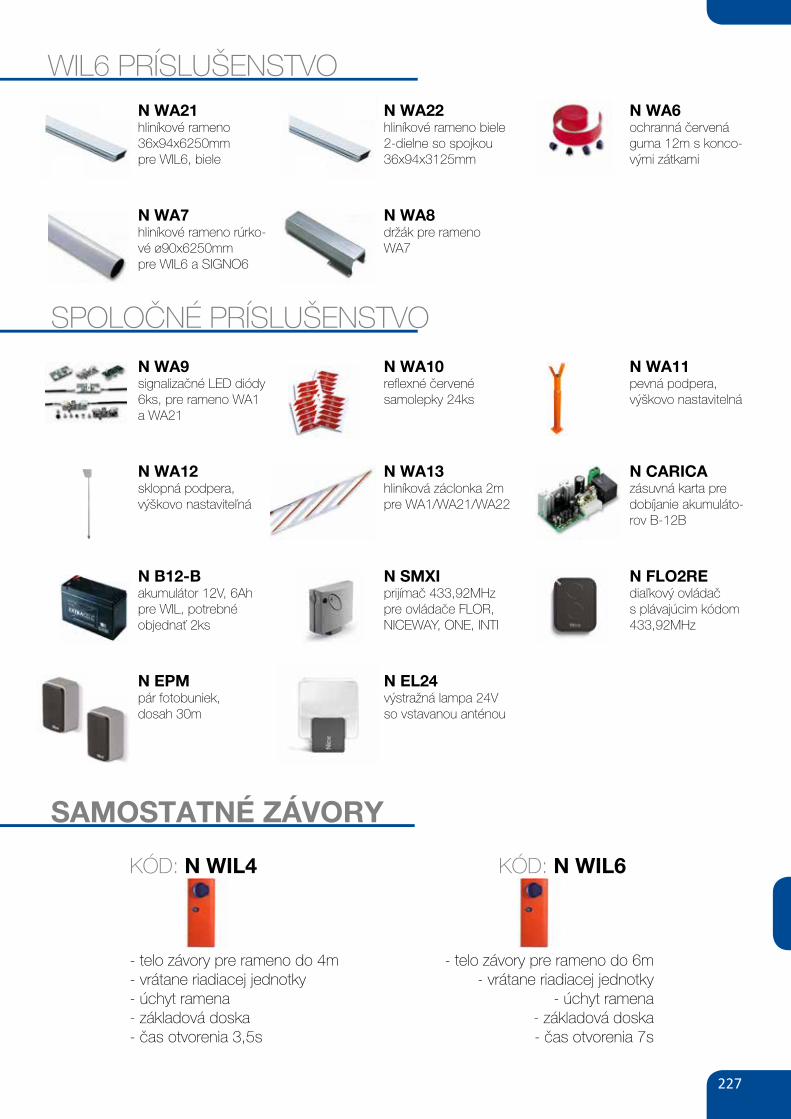
227
SAMOSTATNÉ ZÁVORY
- telo závory pre rameno do 4m- vrátane riadiacej jednotky- úchyt ramena- základová doska- čas otvorenia 3,5s
KÓD: N WIL4
N WA7hliníkové rameno rúrko-vé ø90x6250mmpre WIL6 a SIGNO6
N WA21hliníkové rameno36x94x6250mmpre WIL6, biele
N WA22hliníkové rameno biele2-dielne so spojkou36x94x3125mm
N WA8držák pre rameno WA7
N WA6ochranná červená guma 12m s konco-vými zátkami
- telo závory pre rameno do 6m- vrátane riadiacej jednotky
- úchyt ramena- základová doska- čas otvorenia 7s
KÓD: N WIL6
WIL6 PRÍSLUŠENSTVO
N WA12sklopná podpera,výškovo nastaviteľná
N WA9signalizačné LED diódy 6ks, pre rameno WA1 a WA21
N WA10reflexné červenésamolepky 24ks
N WA13hliníková záclonka 2m pre WA1/WA21/WA22
N WA11pevná podpera,výškovo nastavitelná
N CARICAzásuvná karta pre dobíjanie akumuláto-rov B-12B
SPOLOČNÉ PRÍSLUŠENSTVO
N B12-Bakumulátor 12V, 6Ah pre WIL, potrebné objednať 2ks
N FLO2REdiaľkový ovládačs plávajúcim kódom 433,92MHz
N EPMpár fotobuniek,dosah 30m
N SMXIprijímač 433,92MHz pre ovládače FLOR, NICEWAY, ONE, INTI
N EL24výstražná lampa 24Vso vstavanou anténou
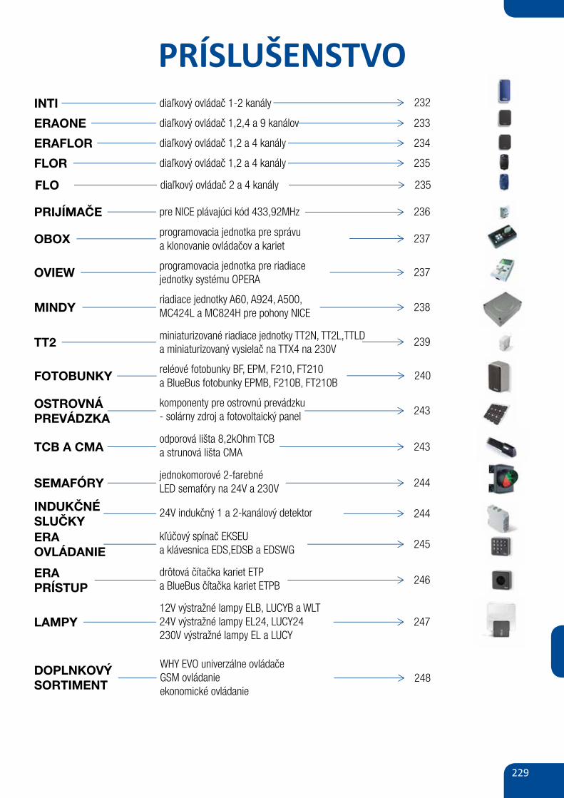
229
PRÍSLUŠENSTVOINTI diaľkový ovládač 1-2 kanály
ERAFLOR
232
diaľkový ovládač 1,2,4 a 9 kanálov 233
diaľkový ovládač 1,2 a 4 kanály 234
diaľkový ovládač 1,2 a 4 kanály 235
OSTROVNÁPREVÁDZKA
programovacia jednotka pre správua klonovanie ovládačov a kariet
237
pre NICE plávajúci kód 433,92MHz 236
programovacia jednotka pre riadiacejednotky systému OPERA
237
riadiace jednotky A60, A924, A500, MC424L a MC824H pre pohony NICE 238
240
miniaturizované riadiace jednotky TT2N, TT2L,TTLDa miniaturizovaný vysielač na TTX4 na 230V
239
komponenty pre ostrovnú prevádzku - solárny zdroj a fotovoltaický panel 243
odporová lišta 8,2kOhm TCBa strunová lišta CMA 243
reléové fotobunky BF, EPM, F210, FT210a BlueBus fotobunky EPMB, F210B, FT210B
INDUKČNÉSLUČKY
jednokomorové 2-farebné LED semafóry na 24V a 230V 244
24V indukčný 1 a 2-kanálový detektor 244
ERAOVLÁDANIE
kľúčový spínač EKSEUa klávesnica EDS,EDSB a EDSWG 245
drôtová čítačka kariet ETPa BlueBus čítačka kariet ETPB 246
12V výstražné lampy ELB, LUCYB a WLT24V výstražné lampy EL24, LUCY24230V výstražné lampy EL a LUCY
247
FLOR
PRIJÍMAČE
OBOX
OVIEW
MINDY
TT2
FOTOBUNKY
TCB A CMA
SEMAFÓRY
ERAPRÍSTUP
LAMPY
ERAONE
diaľkový ovládač 2 a 4 kanály 235FLO
WHY EVO univerzálne ovládačeGSM ovládanieekonomické ovládanie
248DOPLNKOVÝ SORTIMENT
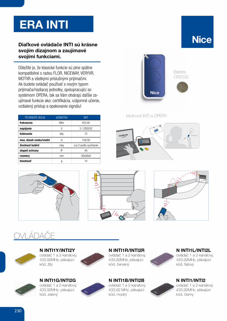
230
ERA INTI
Diaľkové ovládače INTI sú krásne svojím dizajnom a zaujímavésvojími funkciami.
Dôležité je, že klasické funkcie sú plne spätne kompatibilné s radou FLOR, NICEWAY, VERYVR, MOTXR a všetkými príslušnými prijímačmi.Ak budete ovládač používať s novým typom prijímača/riadiacej jednotky, spolupracujíci so systémom OPERA, tak sa Vám otvárajú daľšie za-ujímavé funkcie ako: certifikácia, vzájomné učenie, vzdialený prístup a opakovanie signálu!
TECHNICKÉ ÚDAJE JEDNOTKA INTI
frekvencia MHz 433,92
napájanie V 3 / CR2032
kódovanie bity 72
max. dosah vonku/vnútri m 150/30
životnost batérií roky cca 2 podľa využívania
stupeň ochrany IP 40
rozmery mm 30x56x9
hmotnosť g 14
145
3. 4.2.1.
ERA INTI Control systems
uNINTIVERsAL! Inti, the universal control! Ideal for use in apartment blocks or multi-user systems.Easy and cheap to install: combined with the Ox2 universal receiver, the Inti transmitter is able to control and manage any automation, including pre-installed systems.
CODE ExCHANGE BETWEEN A MEMORIZED TRANSMITTER AND A NEW ONE, TO BE MEMORIZED.
POSSIBLE MEMORISATION USING NICE O-BOxAND THE “CERTIFICATE”
THE PRESENCE OF A “TRANSMITTER”IN THE OxIT, Ox2T AND Ox4T RECEIVERS ALLOWS RADIO CODES TO BE ACCESSED BY MEANS OF THE O-BOx MULTIFUNCTION INTERFACE.
OxIT, Ox2T AND Ox4T RECEIVERS CAN BE USED AS SIGNAL REPEATERS.
145
3. 4.2.1.
ERA INTI Control systems
uNINTIVERsAL! Inti, the universal control! Ideal for use in apartment blocks or multi-user systems.Easy and cheap to install: combined with the Ox2 universal receiver, the Inti transmitter is able to control and manage any automation, including pre-installed systems.
CODE ExCHANGE BETWEEN A MEMORIZED TRANSMITTER AND A NEW ONE, TO BE MEMORIZED.
POSSIBLE MEMORISATION USING NICE O-BOxAND THE “CERTIFICATE”
THE PRESENCE OF A “TRANSMITTER”IN THE OxIT, Ox2T AND Ox4T RECEIVERS ALLOWS RADIO CODES TO BE ACCESSED BY MEANS OF THE O-BOx MULTIFUNCTION INTERFACE.
OxIT, Ox2T AND Ox4T RECEIVERS CAN BE USED AS SIGNAL REPEATERS.OVLÁDAČE
N INTI1Y/INTI2Yovládač 1 a 2-kanálový, 433,92MHz, plávajúci kód, žltý
N INTI1G/INTI2Govládač 1 a 2-kanálový, 433,92MHz, plávajúci kód, zelený
N INTI1R/INTI2Rovládač 1 a 2-kanálový, 433,92MHz, plávajúci kód, červený
N INTI1B/INTI2Bovládač 1 a 2-kanálový, 433,92 MHz, plávajúci kód, modrý
N INTI1L/INTI2Lovládač 1 a 2-kanálový, 433,92MHz, plávajúci kód, fialový
N INTI1/INTI2ovládač 1 a 2-kanálový, 433,92MHz, plávajúci kód, čierny
145
3. 4.2.1.
ERA INTI Control systems
uNINTIVERsAL! Inti, the universal control! Ideal for use in apartment blocks or multi-user systems.Easy and cheap to install: combined with the Ox2 universal receiver, the Inti transmitter is able to control and manage any automation, including pre-installed systems.
CODE ExCHANGE BETWEEN A MEMORIZED TRANSMITTER AND A NEW ONE, TO BE MEMORIZED.
POSSIBLE MEMORISATION USING NICE O-BOxAND THE “CERTIFICATE”
THE PRESENCE OF A “TRANSMITTER”IN THE OxIT, Ox2T AND Ox4T RECEIVERS ALLOWS RADIO CODES TO BE ACCESSED BY MEANS OF THE O-BOx MULTIFUNCTION INTERFACE.
OxIT, Ox2T AND Ox4T RECEIVERS CAN BE USED AS SIGNAL REPEATERS.
145
3. 4.2.1.
ERA INTI Control systems
uNINTIVERsAL! Inti, the universal control! Ideal for use in apartment blocks or multi-user systems.Easy and cheap to install: combined with the Ox2 universal receiver, the Inti transmitter is able to control and manage any automation, including pre-installed systems.
CODE ExCHANGE BETWEEN A MEMORIZED TRANSMITTER AND A NEW ONE, TO BE MEMORIZED.
POSSIBLE MEMORISATION USING NICE O-BOxAND THE “CERTIFICATE”
THE PRESENCE OF A “TRANSMITTER”IN THE OxIT, Ox2T AND Ox4T RECEIVERS ALLOWS RADIO CODES TO BE ACCESSED BY MEANS OF THE O-BOx MULTIFUNCTION INTERFACE.
OxIT, Ox2T AND Ox4T RECEIVERS CAN BE USED AS SIGNAL REPEATERS.
Možnosti INTI a OPERY
145
3. 4.2.1.
ERA INTI Control systems
uNINTIVERsAL! Inti, the universal control! Ideal for use in apartment blocks or multi-user systems.Easy and cheap to install: combined with the Ox2 universal receiver, the Inti transmitter is able to control and manage any automation, including pre-installed systems.
CODE ExCHANGE BETWEEN A MEMORIZED TRANSMITTER AND A NEW ONE, TO BE MEMORIZED.
POSSIBLE MEMORISATION USING NICE O-BOxAND THE “CERTIFICATE”
THE PRESENCE OF A “TRANSMITTER”IN THE OxIT, Ox2T AND Ox4T RECEIVERS ALLOWS RADIO CODES TO BE ACCESSED BY MEANS OF THE O-BOx MULTIFUNCTION INTERFACE.
OxIT, Ox2T AND Ox4T RECEIVERS CAN BE USED AS SIGNAL REPEATERS.
BatériaCR2032
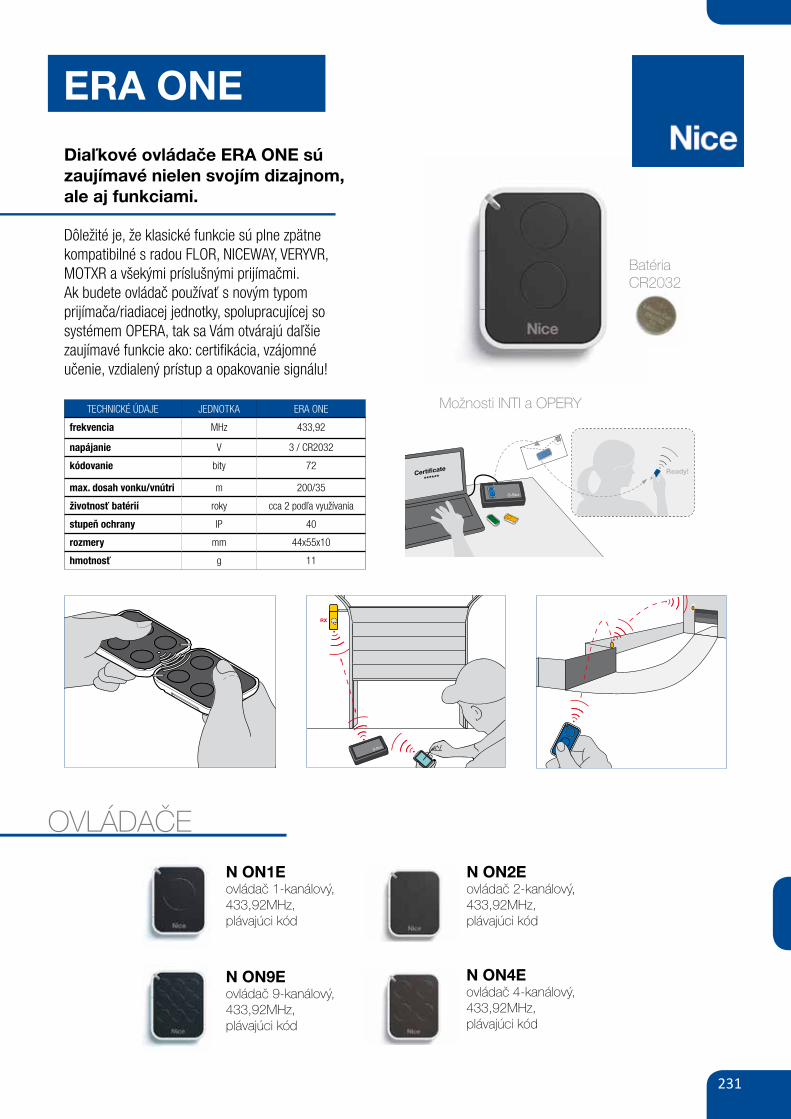
231
ERA ONE
Diaľkové ovládače ERA ONE sú zaujímavé nielen svojím dizajnom, ale aj funkciami.
Dôležité je, že klasické funkcie sú plne zpätne kompatibilné s radou FLOR, NICEWAY, VERYVR, MOTXR a všekými príslušnými prijímačmi.Ak budete ovládač používať s novým typom prijímača/riadiacej jednotky, spolupracujícej so systémem OPERA, tak sa Vám otvárajú daľšiezaujímavé funkcie ako: certifikácia, vzájomnéučenie, vzdialený prístup a opakovanie signálu!
TECHNICKÉ ÚDAJE JEDNOTKA ERA ONE
frekvencia MHz 433,92
napájanie V 3 / CR2032
kódovanie bity 72
max. dosah vonku/vnútri m 200/35
životnosť batérií roky cca 2 podľa využívania
stupeň ochrany IP 40
rozmery mm 44x55x10
hmotnosť g 11
146 GATE&DOOR 2013
ERA ONENEW
2.1.
TRANsmITTER TEChNICAL sPECIFICATIONsCarrier
frequency Estimated range Encoding Power supply Battery lifeProtection
classDimensions
Weight
ON_E, ON_CE 433.92 MHz 200 m (outdoor); 35 m (if inside
buildings)*
O-Code 72 bit; rolling code
3 Vdc; type CR2032
lithium battery
2 years (with 10 transmissions
per day)
IP40 (use in protected
environments)
44x55x10 h mm 11 g
ON_EFm 868.46 MHz
* Transmitter range and receiver reception capacity may be affected by any devices operating on the same frequency in the area.
The system includes 1, 2, 4 and 9 channel transmitters and prewired receivers with connector, with and without built-in transmitter.
433.92 mhz rolling code, with management of Identity Codes and Certificates, self-learning and built-in proximity receiver; with 72 bit O-Code encoding, also compatible with receivers with Nice FLOR encoding.
Available in versions with multiple input sequential encoding (Era OneC).
Evolved: uses data processing and recognition systems that increase its degree of security and deliver a threefold reduction in automation response times.
Easy memorisation, even at a distance, thanks to Opera receivers.
There are two options for enabling a new Inti transmitter, even at a distance from the system: • using a transmitter already programmed in the receiver, thanks to the enabling Code exchange between the two (figure 1); • using the Nice O-Box connection interface; the receiver’s Certificate is entered by just placing the new Era One next to the O-Box and following the guided procedure on a PC or PDA (figure 2).
safe, if a transmitter is stolen or lost, with the O-Box the user can: • replace it, maintaining the same functions as in the previous one, disable the old transmitter by increasing the priority level on the new Era One.
Extremely practical: using the O-Box software, the Era OneC version allows whole packs of 10 devices to be programmed in a single procedure, without even opening them!
Elegant and convenient: the Era One transmitter can be used as a stylish, high-tech keyring or fixed to the wall or your car’s dashboard with the handy support included in the pack.
Era OneFm, ideal for use in cities or places where many devices are present.
868.46 MHz Rolling Code transmitter line, using frequency modulation (FM), less sensitive to interference than amplitude modulation AM.
CODE DESCRIPTION PCS/PACK
ON1E 1 CHANNEL, 433.92 MHz 10ON2E 2 CHANNELS, 433.92 MHz 10ON4E 4 CHANNELS, 433.92 MHz 10ON9E 9 CHANNELS, 433.92 MHz 10ON1CE 1 CHANNEL, 433.92 MHz, WITH MULTIPLE INPUT SEqUENTIAL ENCODING 10ON2CE 2 CHANNELS, 433.92 MHz, WITH MULTIPLE INPUT SEqUENTIAL ENCODING 10ON4CE 4 CHANNELS, 433.92 MHz, WITH MULTIPLE INPUT SEqUENTIAL ENCODING 10ON1EFm 1 CHANNEL, 868.46 MHz 10ON2EFm 2 CHANNELS, 868.46 MHz 10ON4EFm 4 CHANNELS, 868.46 MHz 10ON9EFm 9 CHANNELS, 868.46 MHz 10
ERA ONE TRANsmITTERs
CODE ExCHANGE BETWEEN A MEMORIZED TRANSMITTER AND A NEW ONE, TO BE MEMORIZED.
POSSIBLE MEMORISATION USING NICE O-BOxAND THE “CERTIFICATE”.
145
3. 4.2.1.
ERA INTI Control systems
uNINTIVERsAL! Inti, the universal control! Ideal for use in apartment blocks or multi-user systems.Easy and cheap to install: combined with the Ox2 universal receiver, the Inti transmitter is able to control and manage any automation, including pre-installed systems.
CODE ExCHANGE BETWEEN A MEMORIZED TRANSMITTER AND A NEW ONE, TO BE MEMORIZED.
POSSIBLE MEMORISATION USING NICE O-BOxAND THE “CERTIFICATE”
THE PRESENCE OF A “TRANSMITTER”IN THE OxIT, Ox2T AND Ox4T RECEIVERS ALLOWS RADIO CODES TO BE ACCESSED BY MEANS OF THE O-BOx MULTIFUNCTION INTERFACE.
OxIT, Ox2T AND Ox4T RECEIVERS CAN BE USED AS SIGNAL REPEATERS.OVLÁDAČE
N ON1Eovládač 1-kanálový, 433,92MHz,plávajúci kód
N ON9Eovládač 9-kanálový, 433,92MHz,plávajúci kód
N ON2Eovládač 2-kanálový, 433,92MHz,plávajúci kód
N ON4Eovládač 4-kanálový, 433,92MHz,plávajúci kód
145
3. 4.2.1.
ERA INTI Control systems
uNINTIVERsAL! Inti, the universal control! Ideal for use in apartment blocks or multi-user systems.Easy and cheap to install: combined with the Ox2 universal receiver, the Inti transmitter is able to control and manage any automation, including pre-installed systems.
CODE ExCHANGE BETWEEN A MEMORIZED TRANSMITTER AND A NEW ONE, TO BE MEMORIZED.
POSSIBLE MEMORISATION USING NICE O-BOxAND THE “CERTIFICATE”
THE PRESENCE OF A “TRANSMITTER”IN THE OxIT, Ox2T AND Ox4T RECEIVERS ALLOWS RADIO CODES TO BE ACCESSED BY MEANS OF THE O-BOx MULTIFUNCTION INTERFACE.
OxIT, Ox2T AND Ox4T RECEIVERS CAN BE USED AS SIGNAL REPEATERS.
Možnosti INTI a OPERY
145
3. 4.2.1.
ERA INTI Control systems
uNINTIVERsAL! Inti, the universal control! Ideal for use in apartment blocks or multi-user systems.Easy and cheap to install: combined with the Ox2 universal receiver, the Inti transmitter is able to control and manage any automation, including pre-installed systems.
CODE ExCHANGE BETWEEN A MEMORIZED TRANSMITTER AND A NEW ONE, TO BE MEMORIZED.
POSSIBLE MEMORISATION USING NICE O-BOxAND THE “CERTIFICATE”
THE PRESENCE OF A “TRANSMITTER”IN THE OxIT, Ox2T AND Ox4T RECEIVERS ALLOWS RADIO CODES TO BE ACCESSED BY MEANS OF THE O-BOx MULTIFUNCTION INTERFACE.
OxIT, Ox2T AND Ox4T RECEIVERS CAN BE USED AS SIGNAL REPEATERS.
BatériaCR2032
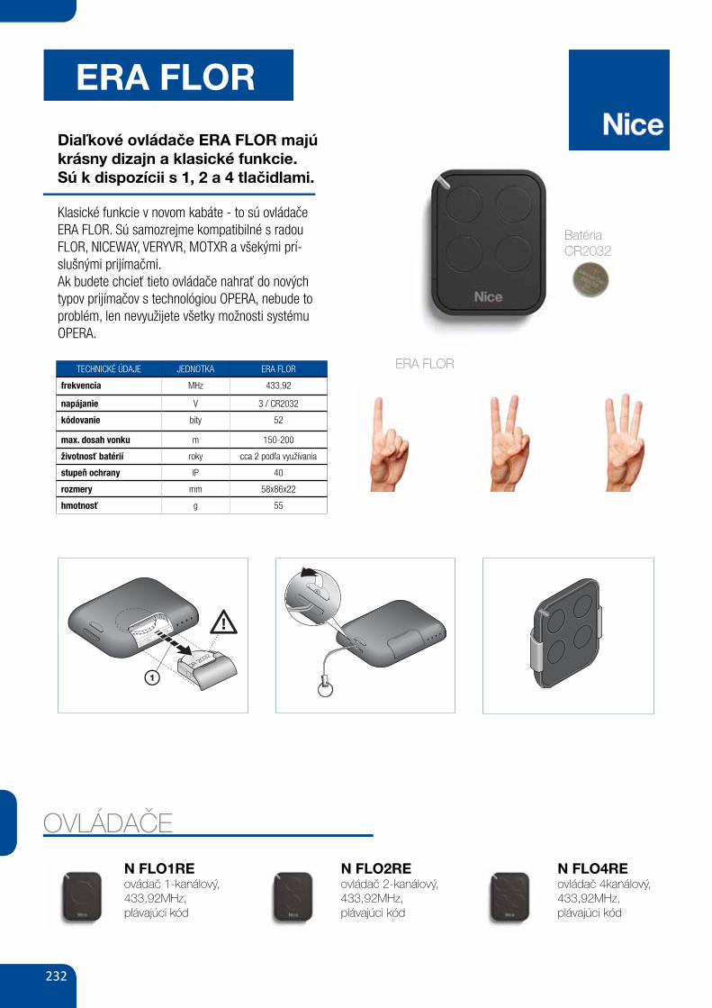
232
ERA FLOR
Diaľkové ovládače ERA FLOR majú krásny dizajn a klasické funkcie.Sú k dispozícii s 1, 2 a 4 tlačidlami.
Klasické funkcie v novom kabáte - to sú ovládače ERA FLOR. Sú samozrejme kompatibilné s radou FLOR, NICEWAY, VERYVR, MOTXR a všekými prí-slušnými prijímačmi.Ak budete chcieť tieto ovládače nahrať do nových typov prijímačov s technológiou OPERA, nebude to problém, len nevyužijete všetky možnosti systému OPERA.
TECHNICKÉ ÚDAJE JEDNOTKA ERA FLOR
frekvencia MHz 433,92
napájanie V 3 / CR2032
kódovanie bity 52
max. dosah vonku m 150-200
životnosť batérií roky cca 2 podľa využívania
stupeň ochrany IP 40
rozmery mm 58x86x22
hmotnosť g 55
OVLÁDAČE
N FLO1REovádač 1-kanálový, 433,92MHz,plávajúci kód
N FLO2REovládač 2-kanálový, 433,92MHz,plávajúci kód
N FLO4REovládač 4kanálový, 433,92MHz,plávajúci kód
ERA FLOR
PRODUCT DESCRIPTION ANDINTENDED USEThis transmitter belongs to the “Era Flor”range of products manufactured by Nice.The transmitters in this range are with vari-able code (rolling-code) and are designedfor the control of automatic door openers,gate openers and similar devices: any oth-er use is improper and prohibited!Models with 1, 2, 4 keys are available (fig.A), as well as the following optional ac -cessories: keyring cord (fig. C); wall-mount-ing support (fig. D).
TESTING THE TRANSMITTERBefore memorizing the transmitter in theautomation system’s Receiver, check itsproper operation by pressing any key andobserving whether the Led lights up (fig.A). If it does not, refer to the section enti-tled “Replacing the Battery” in this manual.
MEMORIZING THE TRANSMITTERThe transmitter is compatible with all theReceivers that use the “Flo-R” coding sys-tem (to identify these models, refer to theNice products catalogue).To memorize the transmitter in a Receiver,you can choose one of the following oper-ating procedures.
A - Memorization “Mode I”This procedure allows you to memorize allthe transmitter keys, at once, in the receiv-er. The keys are automatically associatedto each control managed by the ControlUnit according to a factory-set sequence.
B - Memorization “Mode II”This procedure enables the memorizationof a single transmitter key in the receiver. Inthis case, the user will select from amongthe commands managed by the ControlUnit (4 max) the one he wishes to associ-ate to the key that is being memorized.Note – the procedure must be repeated foreach single key that must be memorized.
Notes to memosisation – The operatingprocedures for these memorization meth-ods are provided in the instruction manualof the Receiver or Control Unit with whichthe transmitter is to be used. These manu-als are also available on the internet site:www.niceforyou.com. In these manuals,the transmitter keys are identified by num-bers. To match these numbers with the cor-rect Era Flor transmitter keys, see fig. A.
REPLACING THE BATTERYWhen the battery runs down the range ofthe transmitter is significantly reduced.When pressing any key you will find thatthe Led takes a while to light up (= batteryalmost exhausted) and that the brightnessof the Led is dimmed (= battery completelyexhausted).In these cases, in order to restore the nor-mal operation of the transmitter, you needto re place the exhausted battery with anew one of the same type, observing thepolarity shown in fig. B.
Battery disposalWarning! – Exhausted batteries containpolluting substances; therefore they maynot be disposed of together with unsortedhousehold waste. They must be disposedof separately according to the regulationslocally in force.
PRODUCT DISPOSALThis product constitutes an integral partof the automation system it controls,therefore it must be disposed of alongwith it.As for the installation, the disposal opera-tions at the end of the product’s effectivelife must be performed by qualified person-nel. This product is made up of differenttypes of material, some of which can berecycled while others must be scrapped.Seek information on the recycling and dis-posal methods envisaged by the local reg-ulations in your area for this product cate-gory. Warning! – Some parts of the prod-
ENGLISHuct may contain polluting or hazardoussubstances that, if incorrectly disposed of,could have a damaging effect on the envi-ronment or on the health of individuals. Asthe symbol on the left indicates,this product may not be dis-posed of with the usual house-hold waste. It must be disposedof separately in compliance with the regu-lations locally in force, or returned to theseller when purchasing a new, equivalentproduct. Warning! – Heavy fines may beimposed by local laws for the illegal dis-posal of this product.
TECHNICAL CHARACTERISTICS OFTHE PRODUCT Power supply: 3Vdc, CR2032 type lithi-um battery Estimated battery life: 2years, with 10 transmissions a day Fre-quency: 433.92 MHz (± 100 kHz) Esti-mated radiated power: ap prox. 1 mWE.R.P. Radio coding: Flo-R, rolling code,52 bit Operating temperature: -20°C;+55°C Estimated ran ge: 200 m (out-side); 35 m (inside buildings) (*) Protec-tion class: IP 40 (for household use or inprotected environments) Dimensions:45 x 56 x 11 mm Weight: 18 g
Notes: • (*) The range of the transmittersand the reception capacity of the Receiversare greatly affected by the presence of oth-er devices (such as alarms, radio headsets,etc..) operating in your area at the samefrequency. In these cases, Nice cannot offerany warranty regarding the actual range ofits devices. • All the technical characteris-tics specified above refer to an ambienttemperature of 20°C (± 5°C). • Nice S.p.a.reserves the right to make modifications tothe product at any time without priornotice, while maintaining the same func-tionality and intended use.
CE DECLARATION OF CONFORMITYNote: The contents of this declaration cor-respond to declarations in the official docu-ment deposited at the registered offices ofNice S.p.a. and in particular to the last revi-sion available before printing this manual.The text herein has been re-edited for edi-torial purposes. A copy of the original dec-laration can be requested from Nice S.p.a.(TV) I.
Number of declaration: 423/ERA-FLOR;Language: EN
The undersigned, Luigi Paro, in the role ofManaging Director of NICE S.p.A. (via Pez-za Alta n°13, 31046 Rustignè di Oderzo(TV) Italy), declares under his sole responsi-bility, that the products FLO1RE, FLO2RE,FLO4RE, conforms to the essential require-ments stated in the European directive1999/5/EC (9 March 1999), for the intend-ed use of products. In accordance with thesame directive (appendix V), the product isclass 1 and marked CE 0682
Ing. Luigi Paro (Managing Director)
Original instructions
DESCRIPTION DU PRODUIT ETAPPLICATIONCet émetteur fait partie de la série « EraFlor » de Nice. Les émetteurs de cettesérie sont à code tournant (rolling-code) etsont destinés à la commande d’automa-tismes pour l’ouverture de portes, portailset autres dispositifs du même type : touteautre utilisation est impropre et doncinterdite !La gamme comprend des modèles à 1, 2,4 touches (fig. A) ainsi que les accessoiressuivants en option : cordon pour porte-clés (fig. C) ; support pour fixation au mur(fig. D).
VÉRIFICATION DE L’ÉMETTEURAvant de mémoriser l’émetteur dans lerécepteur de l’automatisme, vérifier qu’ilfonctionne correctement en pressant l’unedes touches et en observant si la LED s’al-lume au même moment (fig. A). Si elle nes’allume pas, lire le paragraphe « Rempla-cement de la pile » dans ce guide.
MÉMORISATION DE L’ÉMETTEURL’émetteur est compatible avec tous lesrécepteurs qui utilisent le co dage « Flo-R »(pour identifier ces modèles, consulter lecatalogue des produits de Nice).Pour mémoriser l’émetteur dans un récep-teur, il est possible de choisir parmi les pro-cédures opérationnelles suivantes.
A - Mémorisation en « Mode I »Cette procédure permet de mémoriserdans le récepteur, en une seule fois, toutesles touches de l’émetteur. Les touchessont automatiquement associées à chaquecommande gérée par la logique de com-mande, selon un ordre préétabli en usine.
B - Mémorisation en « Modo II »Cette procédure permet de mémoriserdans le récepteur une seule touche del’émetteur. Dans ce cas, c’est l’utilisateurqui choisit parmi les commandes géréespar la logique de commande (4 au maxi-mum), quelle commande il souhaite asso-cier à la touche qu’il est en train de mémo-riser. Note – La procédure doit être répé-tée pour chacune des touches que l’onveut mémoriser.
Notes à la mémorisation – Les procé-dures opérationnelles de ces modalités demémorisation sont fournies dans le guided’utilisation du récepteur ou de la lo giquede commande avec lequel on veut fairefonctionner l’émetteur. Les guides men-tionnés sont également disponibles sur lesite Internet : www.niceforyou.com. Dansces guides, les touches des émetteurssont identifiées par des chiffres. Pourconnaître la correspondance entre ceschiffres et les touches des émetteurs EraFlor, se reporter à la fig. A.
REMPLACEMENT DE LA PILEQuand la pile est usagée, la portée del’émetteur diminue sensiblement. Quandon presse une touche, on note en particu-lier que la LED s’allume en retard (= pilepresque déchargée) ou que l’intensité del’ampoule de la LED faiblit (= pile totale-ment déchargée).Dans ce cas, pour rétablir le fonctionne-ment normal de l’émetteur, changer lapile usagée en utilisant une pile du mêmetype et en respectant la polarité indiquéesur la fig. B.
Mise au rebut de la pileAttention ! – La pile usagée contient dessubstances polluantes et ne doit donc pasêtre jetée avec les ordures ménagères. Ilfaut la mettre au rebut en adoptant lesméthodes de collecte sélective prévuespar les normes en vigueur dans le paysd‘utilisation.
MISE AU REBUT DU PRODUITCe produit fait partie intégrante de l’au-tomatisme qu’il commande et doit doncêtre mis au rebut avec cette dernière.Comme pour les opérations d’installation,
à la fin de la durée de vie de ce produit, lesopérations de démantèlement doivent êtreeffectuées par du personnel qualifié. Ceproduit est constitué de différents types dematériaux dont certains peuvent être recy-clés et d’autres devront être mis au rebut.Informez-vous sur les systèmes de recy-clage ou de mise au rebut prévus par lesrèglements, en vigueur dans votre pays,pour cette catégorie de produit. Atten-tion ! – certains composants du produitpeuvent contenir des substances pol-luantes ou dangereuses qui pourraientavoir des effets nuisibles sur l’environne-ment et sur la santé des personnes s’ilsétaient jetés dans la nature. Comme l’in-dique le symbole ci-contre, il estinterdit de jeter ce produit avecles ordures ménagères. Par con -séquent, utiliser la méthode de la« collecte sélective » pour la mise au rebutdes composants con formément aux pres-criptions des normes en vigueur dans lepays d’utilisation ou restituer le produit auvendeur lors de l’achat d’un nouveau pro-duit équivalent. Attention ! – les règle-ments locaux en vigueur peuvent appliquerde lourdes sanctions en cas d’éliminationillicite de ce produit.
CARACTÉRISTIQUES TECHNIQUESDU PRODUIT Alimentation : pile au lithium de 3 Vcctype CR2032 Durée de la pile : 2 ansenviron, avec 10 transmissions par jour Fréquence : 433.92 MHz (± 100 kHz) Puissance rayonnée : environ 1 mW P.A.R. Codage radio : Flo-R, rolling code, 52bit Température de fonctionnement : -20°C ; +55°C Portée : 200 m environ ;35 m (à l’intérieur) (*) Indice de protec-tion : IP 40 (utilisation à l’intérieur ou dansdes milieux protégés) Dimensions : 45 x56 x 11 mm Poids : 18 g
Notes : • (*) La portée des émetteurs et lacapacité de réception des récepteurs estfortement influencée par d‘autres disposi-tifs (par exemple : alarmes, radio à écou-teurs, etc.) qui fonctionnent dans votrezone à la même fréquence. Dans ces cas,Nice ne peut offrir aucune garantie quant àla portée réelle de ses dispositifs. • Toutesles caractéristiques techniques indiquéesse réfèrent à une température ambiante de20 °C (± 5 °C). • Nice S.p.A. se réserve ledroit d’apporter des modifications au pro-duit chaque fois qu’elle le jugera néces-saire à condition toutefois de garantir lesmêmes fonctions et la même application.
DÉCLARATION CE DE CONFORMITÉNote : Le contenu de cette déclaration deconformité correspond à ce qui est déclarédans le document officiel, déposé au siègede Nice S.p.a., et en particulier à sa der-nière révision disponible avant l’impressionde ce guide. Ce texte a été réadapté pourdes raisons d’édition. Une copie de la décla-ration originale peut être demandée à NiceS.p.a. (TV) I.
Numéro déclaration : 423/ERA-FLOR ;Langue : FR
Je soussigné Luigi Paro, en tant qu’Admi-nistrateur Délégué de NICE S.p.A. (viaPezza Alta n°13, 31046 Rustignè di Oder -zo (TV) Italy), déclare sous ma propre res-ponsabilité que les produits FLO1RE, FL -O2RE, FLO4RE, sont conformes aux exi-gences essentielles de la Directive commu-nautaire 1999/5/CE (9 mars 1999), pourl’utilisation à laquelle les appareils sontdestinés. Conformément à la même direc-tive (annexe V), le produit résulte de classe1 et est marqué CE 0682
Ing. Luigi Paro (Administrateur Délégué)
FRANÇAISInstructions originales
DESCRIPCIÓN DEL PRODUCTO YUSO PREVISTOEl presente transmisor forma parte de laserie “Era Flor” de Nice. Los transmisoresde esta serie estoy con código variable(rolling-code) y están destinados para ac -cionar automatizaciones para abrir y cerrarpuertas, cancelas y similares: ¡cualquierotro uso es considerado inadecuado yestá prohibido!Hay disponibles modelos con 1, 2, 4 boto-nes (fig. A), más los siguientes accesoriosopcionales: cordón para llavero (fig. C);soporte para fijación a la pared (fig. D).
CONTROL DEL TRANSMISORAntes de memorizar el transmisor en el Re -ceptor de la automatización, controle queéste funcione correctamente pulsandocualquier botón y observando, simultánea-mente, el encendido del Led (fig. A). Siéste no se enciende, lea el párrafo “Susti-tución de la ba tería” en este manual.
MEMORIZACIÓN DEL TRANSMISOREl transmisor es compatible con todos losReceptores que adoptan la codificación“Flo-R” (para identificar estos modelos,consulte el catálogo de productos de Nice).Para memorizar el transmisor en un Recep-tor es posible elegir entre los si guientesprocedimientos operativos.
A - Memorización en “Modo I”Este procedimiento permite memorizar enel receptor, en una sola operación, todoslos botones del transmisor. Los botones secombinan automáticamente a cada man-do controlado desde la Central, según unorden predeterminado en fábrica.
B - Memorización en “Modo II”Este procedimiento permite memorizar enel receptor un solo botón del transmisor.En este caso, el usuario deberá elegir,entre los mandos controlados desde laCentral (máximo 4), cuál de estos deseacombinar al botón que está memorizando.Nota – el procedimiento debe repetirse encada botón que se desea memorizar.
Notas sobre la memorización – Les pro-cédures opérationnelles de ces modalitésde mémorisation sont fournies dans le gui-de d’utilisation du récepteur ou de la lo -gique de commande avec lequel on veutfaire fonctionner l’émetteur. Les guidesmentionnés sont également disponiblessur le site Internet: www.niceforyou.com.Dans ces guides, les touches des émet-teurs sont identifiées par des chiffres. Pourconnaître la correspondance entre ceschiffres et les touches des émetteurs EraFlor, se reporter à la fig. A.
SUSTITUCIÓN DE LA BATERÍACuando la batería esté agotada el alcancedel transmisor será mucho más corto. Enparticular, pulsando un botón se notaráque el Led se enciende con retardo (=batería casi agotada), o que la intensidadde la luz del Led es débil (= batería com-pletamente agotada).En dichos casos, para restablecer el fun-cionamiento normal del transmisor, susti-tuya la batería agotada con una del mismotipo, respetando la polaridad indicada enla fig. B.
Eliminación de la batería¡Atención! – La batería agotada contienesustancias contaminantes y, por dichomotivo, no debe arrojarse en los residuosnormales. Hay que eliminarla utilizando losmétodos de recogida selectiva previstospor las normativas vigentes locales.
ELIMINACIÓN DEL PRODUCTOEste producto forma parte integrantede la automatización que acciona y, porconsiguiente, debe eliminarse junto conésta.Al igual que para las operaciones de insta-lación, también al final de la vida útil deeste producto las operaciones de desgua-ce deben ser efectuadas por personal ex -
perto. Este producto está formado de va -rios tipos de materiales: algunos puedenreciclarse y otros deben eliminarse. Infór-mese sobre los sistemas de reciclaje o deeliminación previstos por las normativasvigentes locales para esta categoría deproducto. ¡Atención! – algunas piezas delproducto pueden contener sustancias con-taminantes o peligrosas que, si se lasabandona en el medio ambiente, podríanprovocar efectos perjudiciales para el mis-mo medio ambiente y para la salud huma-na. Tal como indicado por el sím-bolo de aquí al lado, está prohibi-do arrojar este producto a los resi-duos urbanos. Realice la “recogi-da selectiva” para la eliminación, según losmétodos previstos por las normativas vigen-tes locales, o bien entregue el producto alvendedor cuando compre un nuevo pro-ducto equivalente. ¡Atención! – las nor-mas locales pueden prever sanciones impor-tantes en el caso de eliminación abusiva deeste producto.
CARACTERÍSTICAS TÉCNICAS DEL PRODUCTO Alimentación: batería de litio de 3 Vdctipo CR2032 Duración de la batería:estimada en 2 años con 10 transmisionespor día Frecuencia: 433.92 MHz (± 100kHz) Potencia radiada: estimada enalrededor de 1 mW E.R.P. Codificaciónradio: Flo-R, rolling code, 52 bit Tempe-ratura de funcionamiento: -20°C; +55°C Alcance: estimada en 200 m (al airelibre); 35 m (en el interior de edificios) (*) Grado de protección: IP 40 (uso en interio-res o en ambientes protegidos) Dimen-siones: 45 x 56 x 11 mm Peso: 18 g
Notas: • (*) El alcance de los transmisoresy la ca pacidad de recepción de los Recep-tores dependen de otros dispositivos (porejemplo: alarmas, ra dioauriculares, etc..)que funcionen en la zona con la misma fre-cuencia. En estos casos, Nice no puedeofrecer ninguna garantía sobre el alcanceefectivo de sus dispositivos. • To das lascaracterísticas técnicas indicadas se refie-ren a una temperatura de 20°C (± 5°C). •Nice S.p.a se reserva el derecho de modi-ficar los productos en cualquier momentoen que lo considere necesario, mantenien-do las mismas funcionalidades y el mismouso previsto.
DECLARACIÓN DE CONFORMIDADCENota: el contenido de esta declaracióncorresponde a lo declarado en el docu-mento oficial depositado en el domicilio deNice S.p.a. y, en particular, a su última revi-sión disponible antes de la edición de estemanual. El presente texto ha sido readap-tado por motivos de impresión. La copiade la declaración original puede solicitarsea Nice S.p.a. (TV) IT.
Número de declaración: 423/ERA-FLOR;Idioma: ES
El suscrito Luigi Paro, en calidad de Admi-nistrador Delegado de NICE S.p.A. (viaPezza Alta n°13, 31046 Rustignè di Oderzo(TV) Italia), declara bajo su responsabilidadque los productos FLO1RE, FLO2RE,FLO4RE, responden a los requisitos esen-ciales de la Directiva comunitaria 1999/5/CE (9 marzo 1999), para el uso previsto delos equipos. De acuerdo con la misma Di -rectiva (Anexo V), el producto es de clase 1y lleva la marca CE 0682
Ing. Luigi Paro (Administrador Delegado)
ESPAÑOLInstrucciones originales
Instructions for the fitter
Istruzioni per l’installatore
Instructions pour l’installateur
Instrucciones para el instalador
Anweisungen für den installateur
Instrukcje dla instalatora
Aanwijzingen bestemd voor de installateur
IS0101A00MM_19-09-2011
Era FlorTransmitter
CR 2032
1
B
C
D
0682
www.niceforyou.com
Led
(1)
(3)
(2)
(4)
(1)
(2)
(1)
Led
Led
A
FLO1RE
FLO2RE
FLO4RE
BatériaCR2032
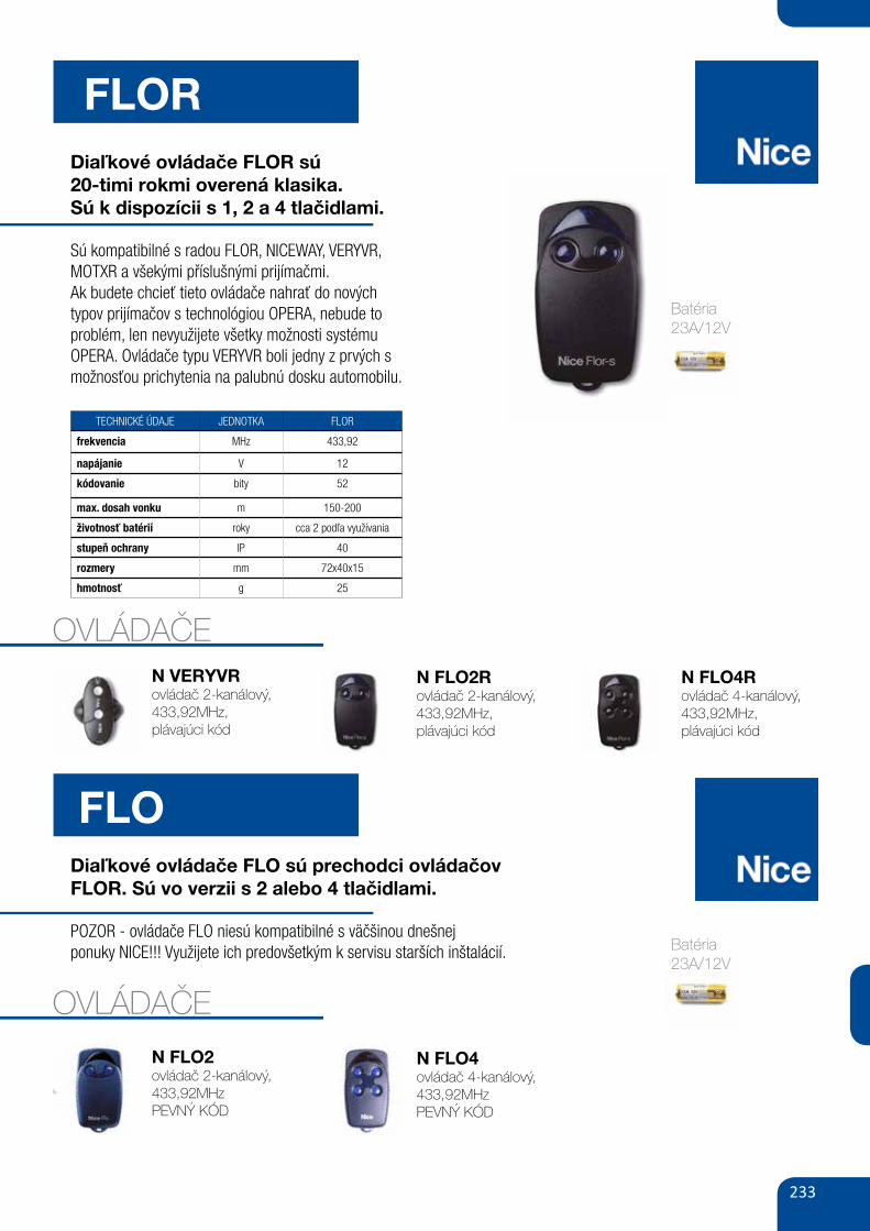
233
FLORDiaľkové ovládače FLOR sú20-timi rokmi overená klasika.Sú k dispozícii s 1, 2 a 4 tlačidlami.
Sú kompatibilné s radou FLOR, NICEWAY, VERYVR,MOTXR a všekými příslušnými prijímačmi.Ak budete chcieť tieto ovládače nahrať do novýchtypov prijímačov s technológiou OPERA, nebude toproblém, len nevyužijete všetky možnosti systémuOPERA. Ovládače typu VERYVR boli jedny z prvých s možnosťou prichytenia na palubnú dosku automobilu.
TECHNICKÉ ÚDAJE JEDNOTKA FLOR
frekvencia MHz 433,92
napájanie V 12
kódovanie bity 52
max. dosah vonku m 150-200
životnosť batérií roky cca 2 podľa využívania
stupeň ochrany IP 40
rozmery mm 72x40x15
hmotnosť g 25
OVLÁDAČEN VERYVRovládač 2-kanálový, 433,92MHz,plávajúci kód
N FLO2Rovládač 2-kanálový, 433,92MHz,plávajúci kód
N FLO4R ovládač 4-kanálový, 433,92MHz,plávajúci kód
FLODiaľkové ovládače FLO sú prechodci ovládačov FLOR. Sú vo verzii s 2 alebo 4 tlačidlami.
POZOR - ovládače FLO niesú kompatibilné s väčšinou dnešnejponuky NICE!!! Využijete ich predovšetkým k servisu starších inštalácií.
OVLÁDAČE
N FLO2ovládač 2-kanálový, 433,92MHzPEVNÝ KÓD
N FLO4ovládač 4-kanálový, 433,92MHzPEVNÝ KÓD
Batéria23A/12V
Batéria23A/12V
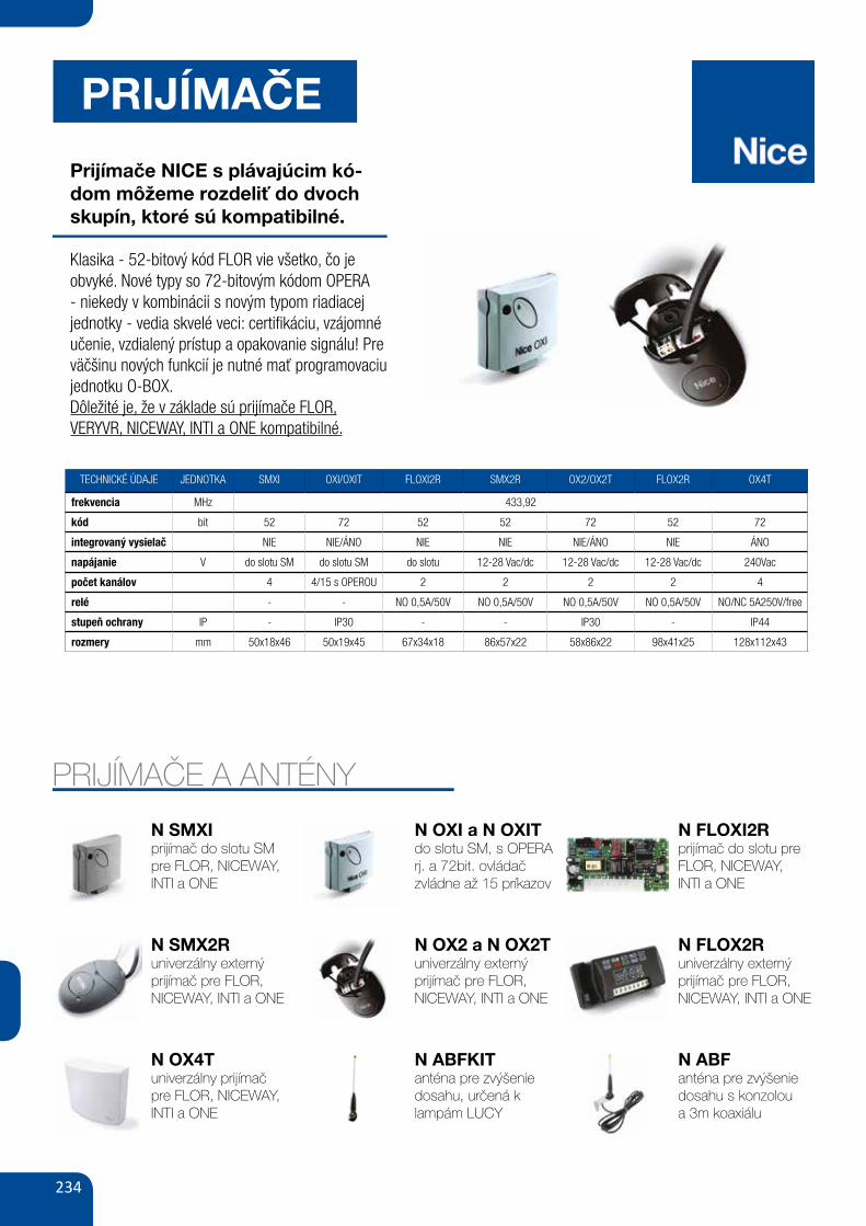
234
PRIJÍMACE
Prijímače NICE s plávajúcim kó-dom môžeme rozdeliť do dvoch skupín, ktoré sú kompatibilné.
Klasika - 52-bitový kód FLOR vie všetko, čo je obvyké. Nové typy so 72-bitovým kódom OPERA - niekedy v kombinácii s novým typom riadiacej jednotky - vedia skvelé veci: certifikáciu, vzájomné učenie, vzdialený prístup a opakovanie signálu! Pre väčšinu nových funkcií je nutné mať programovaciu jednotku O-BOX.Dôležité je, že v základe sú prijímače FLOR,VERYVR, NICEWAY, INTI a ONE kompatibilné.
TECHNICKÉ ÚDAJE JEDNOTKA SMXI OXI/OXIT FLOXI2R SMX2R OX2/OX2T FLOX2R OX4T
frekvencia MHz 433,92
kód bit 52 72 52 52 72 52 72
integrovaný vysielač NIE NIE/ÁNO NIE NIE NIE/ÁNO NIE ÁNO
napájanie V do slotu SM do slotu SM do slotu 12-28 Vac/dc 12-28 Vac/dc 12-28 Vac/dc 240Vac
počet kanálov 4 4/15 s OPEROU 2 2 2 2 4
relé - - NO 0,5A/50V NO 0,5A/50V NO 0,5A/50V NO 0,5A/50V NO/NC 5A250V/free
stupeň ochrany IP - IP30 - - IP30 - IP44
rozmery mm 50x18x46 50x19x45 67x34x18 86x57x22 58x86x22 98x41x25 128x112x43
N OX4Tuniverzálny prijímač pre FLOR, NICEWAY,INTI a ONE
N ABFKITanténa pre zvýšenie dosahu, určená k lampám LUCY
N ABFanténa pre zvýšenie dosahu s konzoloua 3m koaxiálu
PRIJÍMAČE A ANTÉNY
N SMXIprijímač do slotu SM pre FLOR, NICEWAY,INTI a ONE
N SMX2Runiverzálny externý prijímač pre FLOR, NICEWAY, INTI a ONE
N OXI a N OXITdo slotu SM, s OPERA rj. a 72bit. ovládač zvládne až 15 príkazov
N OX2 a N OX2Tuniverzálny externý prijímač pre FLOR, NICEWAY, INTI a ONE
N FLOXI2Rprijímač do slotu pre FLOR, NICEWAY,INTI a ONE
N FLOX2Runiverzálny externý prijímač pre FLOR, NICEWAY, INTI a ONE
ˇ
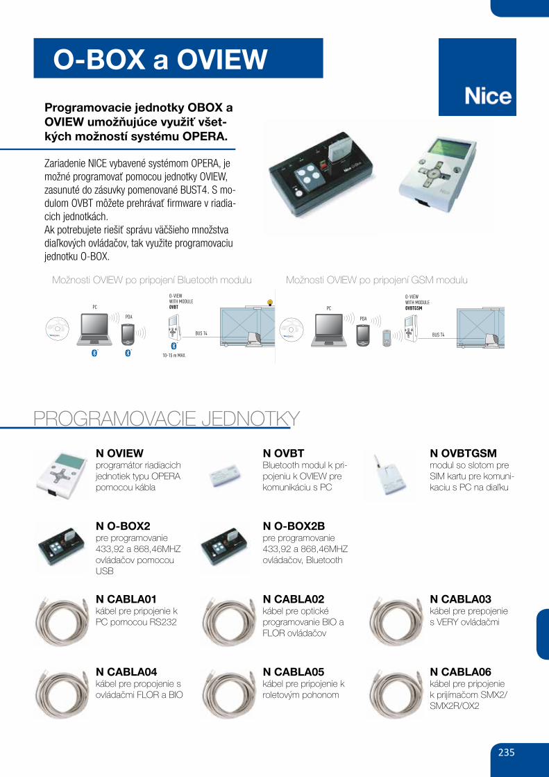
235
O-BOX a OVIEW
Programovacie jednotky OBOX a OVIEW umožňujúce využiť všet-kých možností systému OPERA.
Zariadenie NICE vybavené systémom OPERA, je možné programovať pomocou jednotky OVIEW, zasunuté do zásuvky pomenované BUST4. S mo-dulom OVBT môžete prehrávať firmware v riadia-cich jednotkách.Ak potrebujete riešiť správu väčšieho množstva diaľkových ovládačov, tak využite programovaciu jednotku O-BOX.
PROGRAMOVACIE JEDNOTKY
N OVIEWprogramátor riadiacich jednotiek typu OPERA pomocou kábla
N O-BOX2pre programovanie 433,92 a 868,46MHZ ovládačov pomocou USB
N OVBTBluetooth modul k pri-pojeniu k OVIEW pre komunikáciu s PC
N O-BOX2Bpre programovanie 433,92 a 868,46MHZ ovládačov, Bluetooth
N OVBTGSM modul so slotom pre SIM kartu pre komuni-kaciu s PC na diaľku
161
A-G
RO
UP
SY
SB
US
SCS
TTBus
+ (~)
– (~)BusT4
L4 L3 L1L2
O-VIEW Control systems
PC
PDA
10-15 m MAx.
BUS T4
PC
PDA
BUS T4
O-VIEWWITH MODULE OVbT
O-VIEWWITH MODULE OVbTGsm
OVbT bluetooth connection module for O-View interface. “O-View Software Suite” enables connection via PC or PDA to O-View in the vicinity of the system, to intervene on the control units on the BUS T4 network. Maximum connection distance 15 m.
The interface of “O-View Software Suite” has been specially designed to enable rapid access to all parameters of the connected devices without the need for physical access, as well as quick diagnostics of malfunctions by consulting the event log, all the most practical and intuitive way possible.
The O-View control function has been expanded: in just one PC screen, all applications connected via BUS T4 can be controlled.
OVbTGsm In addition to the benefits of the OVBT module, the automation or network of automations can now be controlled via Gsm by connecting O-View to the system via BUS T4.
A GPRS connection also enables connection via the Internet to O-View to obtain all management functions offered by the software from any location with no need for presence on site.
The user can remotely control the automation via GSM, from any of the enabled numbers, and check status, such as opening a gate by means of a phone call or by sending 4 different controls via SMS text message, with the security offered by entry of a unique password.
O-VIEW sOFTWARE suITE This application, supplied with OVBT and OVBTGSM, as well as expanding the functions of O-View enables the creation of a database of installations with personal data of clients and configurations of each system, even on more complex versions.
There are two versions of software: “O-View Desktop” designed for installation on a PC and “O-View Mobile” which enables use of the functions of the desktop version on a smaller screen of a PDA or Smartphone.
by connecting to the site www.nice-service.com users can download the constantly updated firmware and software versions.
minimum requirements O-View mobile version for PDA palmtop: - Processor: (300 MHz) Recommended by Nice: (> 300 MHz) - RAM: 64 MB Recommended by Nice: 128 MB - Storage memory: 5 MB Recommended by Nice: 20 MB - Operating system: Windows® Mobile 2003 Recommended by Nice: Windows® 5.0 - Connection: Bluetooth® - Graphics resolution: 240 x 320, 256 colours - PC with: CD-Rom (required for software installation on palmtop).
O-View Desktop version for PC: - Processor: type AMD®/Intel® (500 MHz) Recommended by Nice: type AMD®/Intel® (1 GHz) - RAM: 128 MB Recommended by Nice: 256 MB - Free space on disk: 280 MB Recommended by Nice: 512 MB - Operating system: Windows® 98 SE or later Recommended by Nice: Windows® 2000 or later up to Win 7 - Connection: Bluetooth® - Graphics resolution: 800 x 600, 256 colours - Disk drive: CD-Rom (required for installation). Note – software installation includes installation of the program Microsoft®.NET Framework Redistributable 2.0.
INb, the Nice control interface that enables communication between the systems Nice Bus (TTBus and BusT4) and MyHome of BTicino (SCS).
CODE DESCRIPTION PC/PACK
INb COMMUNICATION INTERFACE BETWEEN BTICINO BUS (SCS) AND NICE BUS (TTBUS AND BUST4) 1
TEChNICAL sPECIFICATIONs
Power supply Consumption Insulation Protection rating (IP)Working temp. (°C Min. Max)
Dimensions (mm)
INb to BusT4, or 24 Vac/dc (limits 20 ÷ 35 Vdc, 22 ÷ 35 Vac) approx. 18 mA class III 20 -20÷50 °C 41x52x18h
Možnosti OVIEW po pripojení Bluetooth modulu
N CABLA01kábel pre pripojenie k PC pomocou RS232
N CABLA04kábel pre propojenie s ovládačmi FLOR a BIO
N CABLA02kábel pre optické programovanie BIO a FLOR ovládačov
N CABLA05kábel pre pripojenie k roletovým pohonom
N CABLA03kábel pre prepojenies VERY ovládačmi
N CABLA06kábel pre pripojenie k prijímačom SMX2/SMX2R/OX2
161
A-G
RO
UP
SY
SB
US
SCS
TTBus
+ (~)
– (~)BusT4
L4 L3 L1L2
O-VIEW Control systems
PC
PDA
10-15 m MAx.
BUS T4
PC
PDA
BUS T4
O-VIEWWITH MODULE OVbT
O-VIEWWITH MODULE OVbTGsm
OVbT bluetooth connection module for O-View interface. “O-View Software Suite” enables connection via PC or PDA to O-View in the vicinity of the system, to intervene on the control units on the BUS T4 network. Maximum connection distance 15 m.
The interface of “O-View Software Suite” has been specially designed to enable rapid access to all parameters of the connected devices without the need for physical access, as well as quick diagnostics of malfunctions by consulting the event log, all the most practical and intuitive way possible.
The O-View control function has been expanded: in just one PC screen, all applications connected via BUS T4 can be controlled.
OVbTGsm In addition to the benefits of the OVBT module, the automation or network of automations can now be controlled via Gsm by connecting O-View to the system via BUS T4.
A GPRS connection also enables connection via the Internet to O-View to obtain all management functions offered by the software from any location with no need for presence on site.
The user can remotely control the automation via GSM, from any of the enabled numbers, and check status, such as opening a gate by means of a phone call or by sending 4 different controls via SMS text message, with the security offered by entry of a unique password.
O-VIEW sOFTWARE suITE This application, supplied with OVBT and OVBTGSM, as well as expanding the functions of O-View enables the creation of a database of installations with personal data of clients and configurations of each system, even on more complex versions.
There are two versions of software: “O-View Desktop” designed for installation on a PC and “O-View Mobile” which enables use of the functions of the desktop version on a smaller screen of a PDA or Smartphone.
by connecting to the site www.nice-service.com users can download the constantly updated firmware and software versions.
minimum requirements O-View mobile version for PDA palmtop: - Processor: (300 MHz) Recommended by Nice: (> 300 MHz) - RAM: 64 MB Recommended by Nice: 128 MB - Storage memory: 5 MB Recommended by Nice: 20 MB - Operating system: Windows® Mobile 2003 Recommended by Nice: Windows® 5.0 - Connection: Bluetooth® - Graphics resolution: 240 x 320, 256 colours - PC with: CD-Rom (required for software installation on palmtop).
O-View Desktop version for PC: - Processor: type AMD®/Intel® (500 MHz) Recommended by Nice: type AMD®/Intel® (1 GHz) - RAM: 128 MB Recommended by Nice: 256 MB - Free space on disk: 280 MB Recommended by Nice: 512 MB - Operating system: Windows® 98 SE or later Recommended by Nice: Windows® 2000 or later up to Win 7 - Connection: Bluetooth® - Graphics resolution: 800 x 600, 256 colours - Disk drive: CD-Rom (required for installation). Note – software installation includes installation of the program Microsoft®.NET Framework Redistributable 2.0.
INb, the Nice control interface that enables communication between the systems Nice Bus (TTBus and BusT4) and MyHome of BTicino (SCS).
CODE DESCRIPTION PC/PACK
INb COMMUNICATION INTERFACE BETWEEN BTICINO BUS (SCS) AND NICE BUS (TTBUS AND BUST4) 1
TEChNICAL sPECIFICATIONs
Power supply Consumption Insulation Protection rating (IP)Working temp. (°C Min. Max)
Dimensions (mm)
INb to BusT4, or 24 Vac/dc (limits 20 ÷ 35 Vdc, 22 ÷ 35 Vac) approx. 18 mA class III 20 -20÷50 °C 41x52x18h
Možnosti OVIEW po pripojení GSM modulu
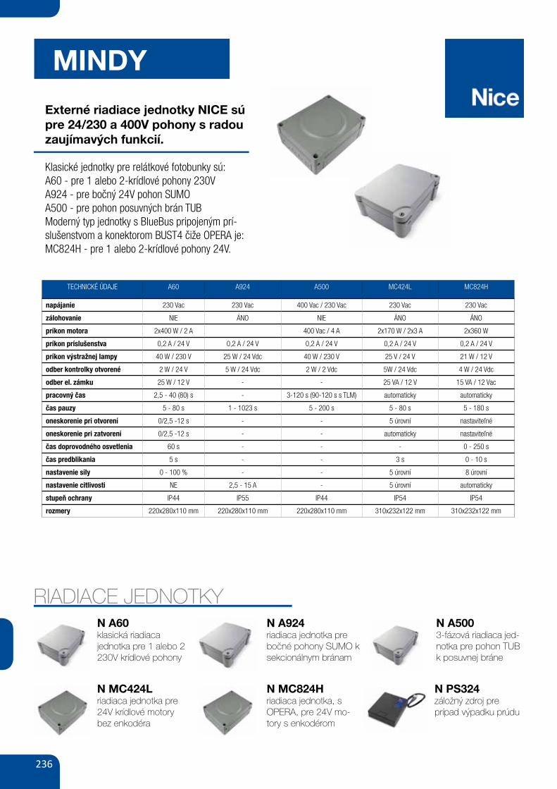
236
MINDY
Externé riadiace jednotky NICE sú pre 24/230 a 400V pohony s radou zaujímavých funkcií.
Klasické jednotky pre relátkové fotobunky sú:A60 - pre 1 alebo 2-krídlové pohony 230VA924 - pre bočný 24V pohon SUMOA500 - pre pohon posuvných brán TUBModerný typ jednotky s BlueBus pripojeným prí-slušenstvom a konektorom BUST4 čiže OPERA je: MC824H - pre 1 alebo 2-krídlové pohony 24V.
TECHNICKÉ ÚDAJE A60 A924 A500 MC424L MC824H
napájanie 230 Vac 230 Vac 400 Vac / 230 Vac 230 Vac 230 Vac
zálohovanie NIE ÁNO NIE ÁNO ÁNO
príkon motora 2x400 W / 2 A 400 Vac / 4 A 2x170 W / 2x3 A 2x360 W
príkon príslušenstva 0,2 A / 24 V 0,2 A / 24 V 0,2 A / 24 V 0,2 A / 24 V 0,2 A / 24 V
príkon výstražnej lampy 40 W / 230 V 25 W / 24 Vdc 40 W / 230 V 25 V / 24 V 21 W / 12 V
odber kontrolky otvorené 2 W / 24 V 5 W / 24 Vdc 2 W / 2 Vdc 5W / 24 Vdc 4 W / 24 Vdc
odber el. zámku 25 W / 12 V - - 25 VA / 12 V 15 VA / 12 Vac
pracovný čas 2,5 - 40 (80) s - 3-120 s (90-120 s s TLM) automaticky automaticky
čas pauzy 5 - 80 s 1 - 1023 s 5 - 200 s 5 - 80 s 5 - 180 s
oneskorenie pri otvorení 0/2,5 -12 s - - 5 úrovní nastaviteľné
oneskorenie pri zatvorení 0/2,5 -12 s - - automaticky nastaviteľné
čas doprovodného osvetlenia 60 s - - - 0 - 250 s
čas predblikania 5 s - - 3 s 0 - 10 s
nastavenie sily 0 - 100 % - - 5 úrovní 8 úrovní
nastavenie citlivosti NE 2,5 - 15 A - 5 úrovní automaticky
stupeň ochrany IP44 IP55 IP44 IP54 IP54
rozmery 220x280x110 mm 220x280x110 mm 220x280x110 mm 310x232x122 mm 310x232x122 mm
RIADIACE JEDNOTKYN A60klasická riadiaca jednotka pre 1 alebo 2 230V krídlové pohony
N MC424Lriadiaca jednotka pre 24V krídlové motory bez enkodéra
N A924riadiaca jednotka pre bočné pohony SUMO k sekcionálnym bránam
N PS324záložný zdroj preprípad výpadku prúdu
N A5003-fázová riadiaca jed-notka pre pohon TUB k posuvnej bráne
N MC824Hriadiaca jednotka, s OPERA, pre 24V mo-tory s enkodérom
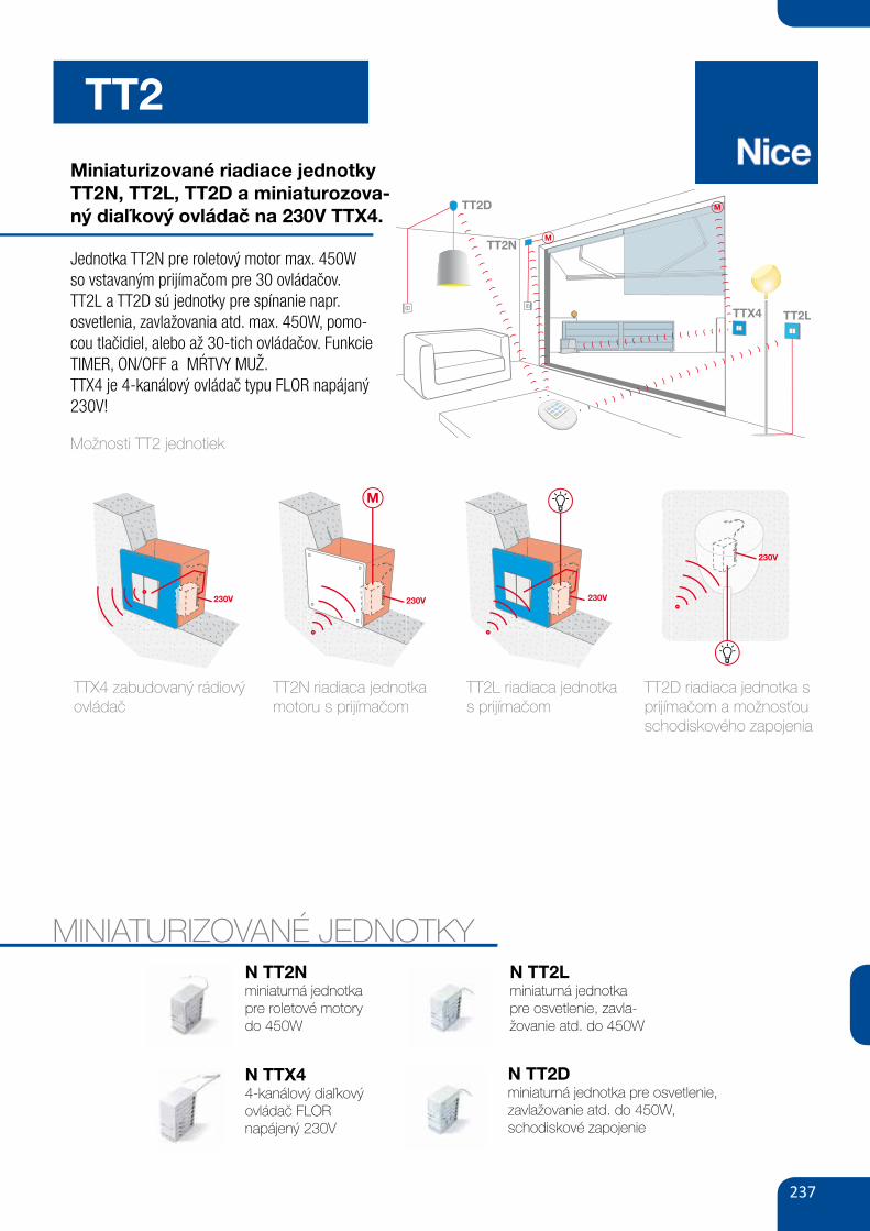
237
TT2
164 GATE&DOOR 2013
TAG sysTEmTT2D
TT2N
TT2L
M
M
TTX4
230V
230V
230V
230V
M
230V
230V
230V
230V
M
230V
230V
230V
230V
M
230V
230V
230V
230V
M
1 2 3 4
Ideal for restorations and upgrades of existing systems. The Tag system, disappearing inside standard wall mounted plates and suitable to confined spaces, are ideal for restorations and upgrades of existing systems to control home automations, lighting points and all loads up to 500 W not directly accessible from cable controls.
All without the need to replace the existing system or involve building work!
1. TTx4: recessed transmitter with mains power supply. Ideal for the control of automations not directly accessible from cable controls. 2. TT2N: miniaturised control unit for control of a 230 Vac motor up to 500 W, with built-in radio receiver. 3. TT2L: miniaturised control unit for control of lighting systems, with built-in radio receiver. 4. TT2D: miniaturised control unit for control of lighting systems from multiple points, with built-in radio receiver and switch.
Miniaturizované riadiace jednotky TT2N, TT2L, TT2D a miniaturozova-ný diaľkový ovládač na 230V TTX4.
Jednotka TT2N pre roletový motor max. 450Wso vstavaným prijímačom pre 30 ovládačov.TT2L a TT2D sú jednotky pre spínanie napr. osvetlenia, zavlažovania atd. max. 450W, pomo-cou tlačidiel, alebo až 30-tich ovládačov. Funkcie TIMER, ON/OFF a MŔTVY MUŽ.TTX4 je 4-kanálový ovládač typu FLOR napájaný 230V!
MINIATURIZOVANÉ JEDNOTKYN TT2Nminiaturná jednotka pre roletové motorydo 450W
N TTX44-kanálový diaľkový ovládač FLORnapájený 230V
N TT2Lminiaturná jednotka pre osvetlenie, zavla-žovanie atd. do 450W
N TT2D miniaturná jednotka pre osvetlenie, zavlažovanie atd. do 450W,schodiskové zapojenie
164 GATE&DOOR 2013
TAG sysTEmTT2D
TT2N
TT2L
M
M
TTX4
230V
230V
230V
230V
M
230V
230V
230V
230V
M
230V
230V
230V
230V
M
230V
230V
230V
230V
M
1 2 3 4
Ideal for restorations and upgrades of existing systems. The Tag system, disappearing inside standard wall mounted plates and suitable to confined spaces, are ideal for restorations and upgrades of existing systems to control home automations, lighting points and all loads up to 500 W not directly accessible from cable controls.
All without the need to replace the existing system or involve building work!
1. TTx4: recessed transmitter with mains power supply. Ideal for the control of automations not directly accessible from cable controls. 2. TT2N: miniaturised control unit for control of a 230 Vac motor up to 500 W, with built-in radio receiver. 3. TT2L: miniaturised control unit for control of lighting systems, with built-in radio receiver. 4. TT2D: miniaturised control unit for control of lighting systems from multiple points, with built-in radio receiver and switch.TTX4 zabudovaný rádiový
ovládač
Možnosti TT2 jednotiek
TT2N riadiaca jednotka motoru s prijímačom
TT2L riadiaca jednotkas prijímačom
TT2D riadiaca jednotka s prijímačom a možnosťou schodiskového zapojenia
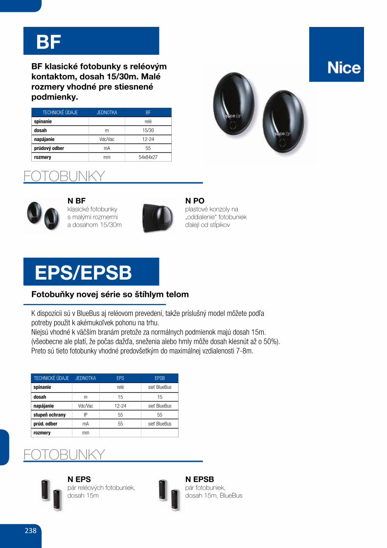
238
BFBF klasické fotobunky s reléovým kontaktom, dosah 15/30m. Malé rozmery vhodné pre stiesnené podmienky.
TECHNICKÉ ÚDAJE JEDNOTKA BF
spínanie relé
dosah m 15/30
napájanie Vdc/Vac 12-24
prúdový odber mA 55
rozmery mm 54x84x27
FOTOBUNKY
N EPSpár reléových fotobuniek, dosah 15m
N EPSBpár fotobuniek,dosah 15m, BlueBus
FOTOBUNKY
N BFklasické fotobunkys malými rozmermia dosahom 15/30m
N POplastové konzoly na „oddialenie“ fotobuniek ďalejl od stĺpikov
EPS/EPSBFotobuňky novej série so štíhlym telom
K dispozícii sú v BlueBus aj reléovom prevedení, takže príslušný model môžete podľa potreby použit k akémukoľvek pohonu na trhu.Niejsú vhodné k väčším branám pretože za normálnych podmienok majú dosah 15m. (všeobecne ale platí, že počas dažďa, sneženia alebo hmly môže dosah klesnút až o 50%).Preto sú tieto fotobunky vhodné predovšetkým do maximálnej vzdialenosti 7-8m.
TECHNICKÉ ÚDAJE JEDNOTKA EPS EPSB
spínanie relé sieť BlueBus
dosah m 15 15
napájanie Vdc/Vac 12-24 sieť BlueBus
stupeň ochrany IP 55 55
prúd. odber mA 55 sieť BlueBus
rozmery mm
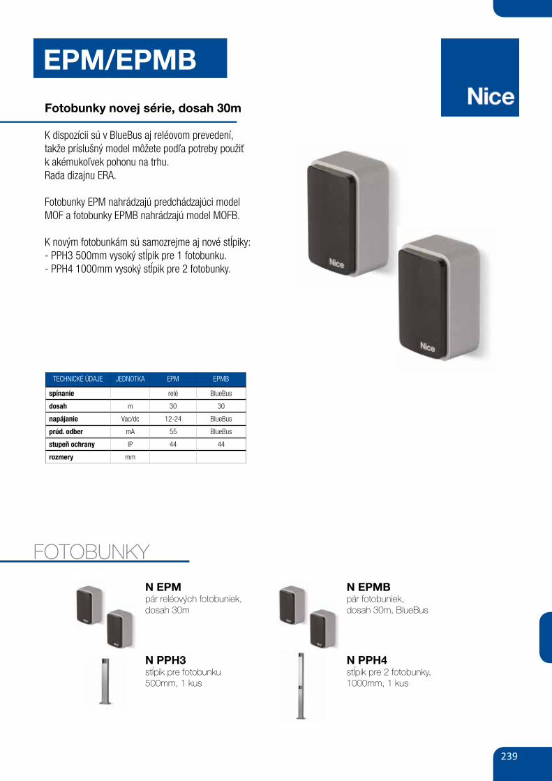
239
EPM/EPMB
Fotobunky novej série, dosah 30m
K dispozícii sú v BlueBus aj reléovom prevedení,takže príslušný model môžete podľa potreby použiťk akémukoľvek pohonu na trhu.Rada dizajnu ERA.
Fotobunky EPM nahrádzajú predchádzajúci model MOF a fotobunky EPMB nahrádzajú model MOFB.
K novým fotobunkám sú samozrejme aj nové stĺpiky:- PPH3 500mm vysoký stĺpik pre 1 fotobunku.- PPH4 1000mm vysoký stĺpik pre 2 fotobunky.
FOTOBUNKY
N EPMpár reléových fotobuniek,dosah 30m
N PPH3stĺpik pre fotobunku 500mm, 1 kus
N EPMBpár fotobuniek,dosah 30m, BlueBus
N PPH4stĺpik pre 2 fotobunky, 1000mm, 1 kus
TECHNICKÉ ÚDAJE JEDNOTKA EPM EPMB
spínanie relé BlueBus
dosah m 30 30
napájanie Vac/dc 12-24 BlueBus
prúd. odber mA 55 BlueBus
stupeň ochrany IP 44 44
rozmery mm
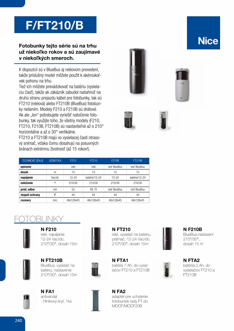
240
F/FT210/B
Fotobunky tejto série sú na trhuuž niekoľko rokov a sú zaujímavév niekoľkých smeroch.
K dispozícii sú v BlueBus aj reléovom prevedení, takže príslušný model môžete použit k akémukoľ-vek pohonu na trhu.Tiež ich môžete prevádzkovať na batériu (vysiela-ciu časť), takže ak zákázník zabudol natiahnúť na druhú stranu prejazdu kábel pre fotobunky, tak sú FT210 (reléová) alebo FT210B (BlueBus) fotobun-ky riešením. Modely F210 a F210B sú drátové.Ak ale „len“ potrebujete vyriešiť natočenie foto-bunky, tak využijte toho, že všetny modely (F210, FT210, F210B, FT210B) sú nastaviteľné až o 210° horizontálne a až o 30° vertikálne.FT210 a FT210B majú vo vysielacej časti otraso-vý snímač, vďaka čomu dosahujú na posuvných bránach extrémnu životnosť (až 15 rokov!).
FOTOBUNKYN F210relé, napájanie 12-24 Vac/dc, 210°/30°, dosah 15m
N FT210BBlueBus, vysielač na batériu, nastavenie 210°/30°, dosah 15m
N FT210relé, vysielač na batériu, prijímač, 12-24 Vac/dc, 210°/30°, dosah 15m
N FTA1batéria 7 Ah, do vysie-lačov FT210 a FT210B
N F210BBlueBus,nastavení 210°/30°,dosah 15 m
N FTA2 batériia 2 Ah, do vysielačov FT210 a FT210B
N FA1antivandal- hliníkový kryt, 1ks
N FA2adaptér pre uchytenie fotobuniek rady FT do MOCF/MOCF20B
TECHNICKÉ ÚDAJE JEDNOTKA F210 FT210 F210B FT210B
spínanie relé relé sieť BlueBus sieť BlueBus
dosah m 15 15 15 15
napájanie Vac/dc 12-24 batérie/12-24 12-24 batérie/12-24
natočenie ° 210/30 210/30 210/30 210/30
prúd. odber mA 55 RX 70 sieť BlueBus sieť BlueBus
stupeň ochrany IP 44 44 44 44
rozmery mm 46x128x45 46x128x45 46x128x45 46x128x45
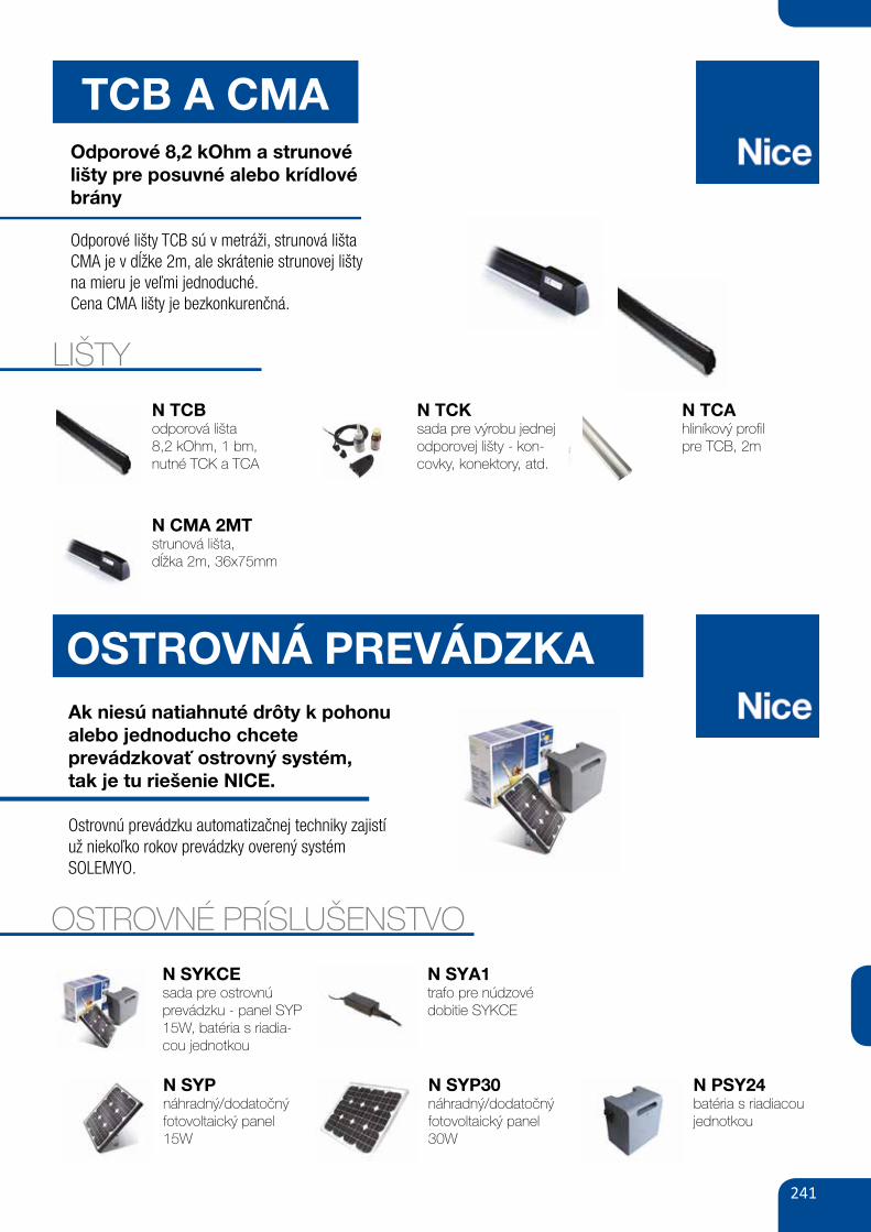
241
OSTROVNÁ PREVÁDZKAAk niesú natiahnuté drôty k pohonu alebo jednoducho chceteprevádzkovať ostrovný systém,tak je tu riešenie NICE.
Ostrovnú prevádzku automatizačnej techniky zajistí už niekoľko rokov prevádzky overený systémSOLEMYO.
OSTROVNÉ PRÍSLUŠENSTVO
TCB A CMAOdporové 8,2 kOhm a strunové lišty pre posuvné alebo krídlové brány
Odporové lišty TCB sú v metráži, strunová lišta CMA je v dĺžke 2m, ale skrátenie strunovej lištyna mieru je veľmi jednoduché.Cena CMA lišty je bezkonkurenčná.
LIŠTY
N TCBodporová lišta 8,2 kOhm, 1 bm, nutné TCK a TCA
174 GATE&DOOR 2013
NICE&sAFE
TCETCb65 Dbm5, Dbm7,5, Dbm10TCk NsFb, NsFsTCF TCA65
8.2 kOhm resistive sensitive edges, maximum safety and control of the automation.
safer: if there are any faults in the system like, for example, the product itself has broken down, the edges will communicate this to the control unit. The TCE interface board enables users to connect sensitive edges (with 8.2 KOhm resistance) to those control units which are not equipped with a special input.
The length can be personalised: the components supplied in the kits enable installers to build sensitive edges of the correct dimension.
Practical: they adapt to any kind of situation and can be installed quickly.
Reliable: the new Class3 technology means that the control unit, the sensitive edges are connected to, can understand if the device is functioning correctly, or if it is out of use.
8.2 kOhm analogical-type input.
Resistive sensitive edges and accessoriesCODE DESCRIPTION PACK
TCb65 SENSITIVE EDGE IN 10 m ROLLS 1TCk KIT PUTTING TOGETHER 8 SENSITIVE EDGES COMPLETE WITH:
- TERMINAL CAPS (TCT65) 16- CONNECTORS, COMPLETE WITH CABLE L=250 CM (TCS250) 8- CONNECTORS 8.2 KOHM (TCER) 8- TIN OF GLUE (TCC) 1- TIN OF PRIMER (TCP) 1
TCF SCISSORS FOR CUTTING SAFETY SENSITIVE EDGES 1TCA65 ALUMINIUM PROFILE L=200 CM 5TCE CONTROL INTERFACE FOR SENSITIVE EDGE 1
Electrical connection devices for safety sensitive edges on moveable leafsCODE DESCRIPTION PACK
Dbm5 COMPLETE KIT FOR GATES UP TO 5 m 1Dbm7,5 COMPLETE KIT FOR GATES UP TO 7.5 m 1Dbm10 COMPLETE KIT FOR GATES UP TO 10 m 1
Instruments and software for force impact measurementCODE DESCRIPTIONNsFb BLUEFORCE INSTRUMENT FOR MEASURING THE IMPACT FORCE
COMPLIANT WITH EN12445, WITH BLUETOOTH/USB INTERFACEAND SOFTWARE INCLUDED, COMPLETE WITH CARRY CASE
NsFs SPEEDFORCE INSTRUMENT FOR MEASURING THE IMPACT FORCECOMPLIANT WITH EN12445, WITH USB INTERFACE AND SOFTWARE INCLUDED COMPLETE WITH CARRY CASE
NsEL STRAIGHT ExTENSION FOR MEASUREMENTS FROM 30 TO 50 CM, APPLICABLE ON NSFB AND NSFS
NsEA ANGULAR ExTENSION FOR MEASUREMENTS FROM 1.25 TO 2.50 m, APPLICABLE ON NSEL
NssWPDA BLUEFORCE PDA SOFTWARE FOR POCKET-PC, FOR NSFB
N TCKsada pre výrobu jednej odporovej lišty - kon-covky, konektory, atd.
174 GATE&DOOR 2013
NICE&sAFE
TCETCb65 Dbm5, Dbm7,5, Dbm10TCk NsFb, NsFsTCF TCA65
8.2 kOhm resistive sensitive edges, maximum safety and control of the automation.
safer: if there are any faults in the system like, for example, the product itself has broken down, the edges will communicate this to the control unit. The TCE interface board enables users to connect sensitive edges (with 8.2 KOhm resistance) to those control units which are not equipped with a special input.
The length can be personalised: the components supplied in the kits enable installers to build sensitive edges of the correct dimension.
Practical: they adapt to any kind of situation and can be installed quickly.
Reliable: the new Class3 technology means that the control unit, the sensitive edges are connected to, can understand if the device is functioning correctly, or if it is out of use.
8.2 kOhm analogical-type input.
Resistive sensitive edges and accessoriesCODE DESCRIPTION PACK
TCb65 SENSITIVE EDGE IN 10 m ROLLS 1TCk KIT PUTTING TOGETHER 8 SENSITIVE EDGES COMPLETE WITH:
- TERMINAL CAPS (TCT65) 16- CONNECTORS, COMPLETE WITH CABLE L=250 CM (TCS250) 8- CONNECTORS 8.2 KOHM (TCER) 8- TIN OF GLUE (TCC) 1- TIN OF PRIMER (TCP) 1
TCF SCISSORS FOR CUTTING SAFETY SENSITIVE EDGES 1TCA65 ALUMINIUM PROFILE L=200 CM 5TCE CONTROL INTERFACE FOR SENSITIVE EDGE 1
Electrical connection devices for safety sensitive edges on moveable leafsCODE DESCRIPTION PACK
Dbm5 COMPLETE KIT FOR GATES UP TO 5 m 1Dbm7,5 COMPLETE KIT FOR GATES UP TO 7.5 m 1Dbm10 COMPLETE KIT FOR GATES UP TO 10 m 1
Instruments and software for force impact measurementCODE DESCRIPTIONNsFb BLUEFORCE INSTRUMENT FOR MEASURING THE IMPACT FORCE
COMPLIANT WITH EN12445, WITH BLUETOOTH/USB INTERFACEAND SOFTWARE INCLUDED, COMPLETE WITH CARRY CASE
NsFs SPEEDFORCE INSTRUMENT FOR MEASURING THE IMPACT FORCECOMPLIANT WITH EN12445, WITH USB INTERFACE AND SOFTWARE INCLUDED COMPLETE WITH CARRY CASE
NsEL STRAIGHT ExTENSION FOR MEASUREMENTS FROM 30 TO 50 CM, APPLICABLE ON NSFB AND NSFS
NsEA ANGULAR ExTENSION FOR MEASUREMENTS FROM 1.25 TO 2.50 m, APPLICABLE ON NSEL
NssWPDA BLUEFORCE PDA SOFTWARE FOR POCKET-PC, FOR NSFB
N TCAhliníkový profilpre TCB, 2m
N CMA 2MTstrunová lišta,dĺžka 2m, 36x75mm
N SYPnáhradný/dodatočný fotovoltaický panel 15W
N SYKCEsada pre ostrovnú prevádzku - panel SYP 15W, batéria s riadia-cou jednotkou
N SYP30náhradný/dodatočný fotovoltaický panel 30W
N SYA1trafo pre núdzové dobitie SYKCE
N PSY24batéria s riadiacou jednotkou
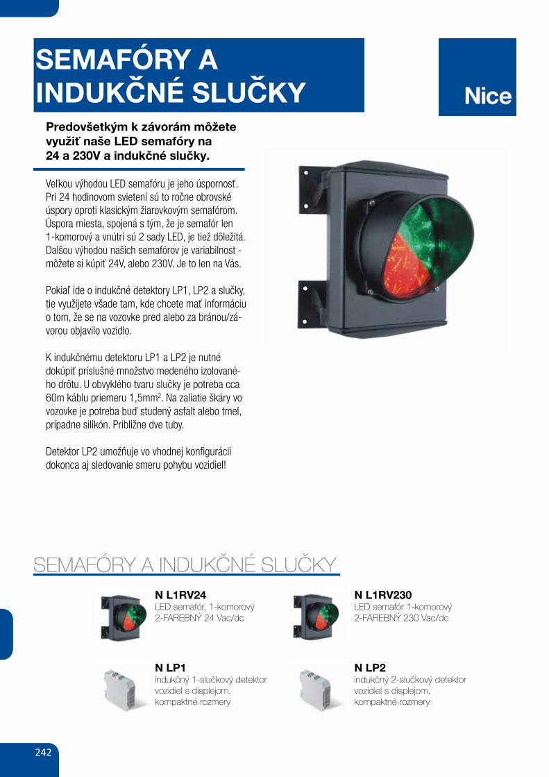
242
SEMAFÓRY AINDUKCNÉ SLUCKY
Predovšetkým k závorám môžete využiť naše LED semafóry na24 a 230V a indukčné slučky.
Veľkou výhodou LED semafóru je jeho úspornosť. Pri 24 hodinovom svietení sú to ročne obrovské úspory oproti klasickým žiarovkovým semafórom. Úspora miesta, spojená s tým, že je semafór len 1-komorový a vnútri sú 2 sady LED, je tiež dôležitá.Dalšou výhodou našich semafórov je variabilnost - môžete si kúpiť 24V, alebo 230V. Je to len na Vás.
Pokiaľ ide o indukčné detektory LP1, LP2 a slučky, tie využijete všade tam, kde chcete mať informáciu o tom, že se na vozovke pred alebo za bránou/zá-vorou objavilo vozidlo.
K indukčnému detektoru LP1 a LP2 je nutné dokúpiť príslušné množstvo medeného izolované-ho drôtu. U obvyklého tvaru slučky je potreba cca 60m káblu priemeru 1,5mm2. Na zaliatie škáry vo vozovke je potreba buď studený asfalt alebo tmel, prípadne silikón. Približne dve tuby.
Detektor LP2 umožňuje vo vhodnej konfigurácii dokonca aj sledovanie smeru pohybu vozidiel!
SEMAFÓRY A INDUKČNÉ SLUČKYN L1RV24LED semafór, 1-komorový2-FAREBNÝ 24 Vac/dc
N LP1indukčný 1-slučkový detektor vozidiel s displejom,kompaktné rozmery
N L1RV230LED semafór 1-komorový2-FAREBNÝ 230 Vac/dc
N LP2indukčný 2-slučkový detektor vozidiel s displejom,kompaktné rozmery
ˇ ˇ
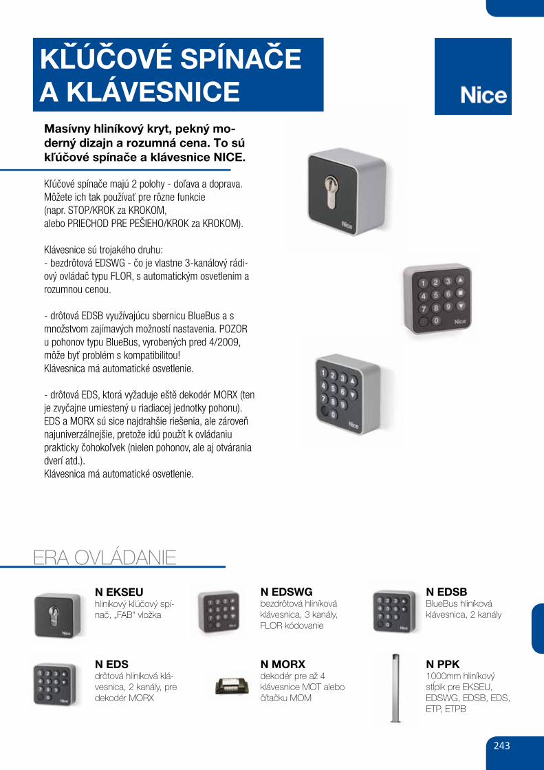
243
KLÚCOVÉ SPÍNACEA KLÁVESNICEMasívny hliníkový kryt, pekný mo-derný dizajn a rozumná cena. To sú kľúčové spínače a klávesnice NICE.
Kľúčové spínače majú 2 polohy - doľava a doprava.Môžete ich tak používať pre rôzne funkcie(napr. STOP/KROK za KROKOM,alebo PRIECHOD PRE PEŠIEHO/KROK za KROKOM).
Klávesnice sú trojakého druhu:- bezdrôtová EDSWG - čo je vlastne 3-kanálový rádi-ový ovládač typu FLOR, s automatickým osvetlením a rozumnou cenou.
- drôtová EDSB využívajúcu sbernicu BlueBus a s množstvom zajímavých možností nastavenia. POZOR u pohonov typu BlueBus, vyrobených pred 4/2009, môže byť problém s kompatibilitou!Klávesnica má automatické osvetlenie.
- drôtová EDS, ktorá vyžaduje eště dekodér MORX (ten je zvyčajne umiestený u riadiacej jednotky pohonu). EDS a MORX sú sice najdrahšie riešenia, ale zároveň najuniverzálnejšie, pretože idú použít k ovládaniu prakticky čohokoľvek (nielen pohonov, ale aj otvárania dverí atd.).Klávesnica má automatické osvetlenie.
ERA OVLÁDANIE
N EKSEUhliníkový kľúčový spí-nač, „FAB“ vložka
N EDSdrôtová hliníková klá-vesnica, 2 kanály, pre dekodér MORX
N MORXdekodér pre až 4 klávesnice MOT alebo čítačku MOM
N PPK1000mm hliníkový stĺpik pre EKSEU, EDSWG, EDSB, EDS, ETP, ETPB
N EDSWGbezdrôtová hliníková klávesnica, 3 kanály, FLOR kódovanie
N EDSBBlueBus hliníková klávesnica, 2 kanály
ˇˇ ˇ
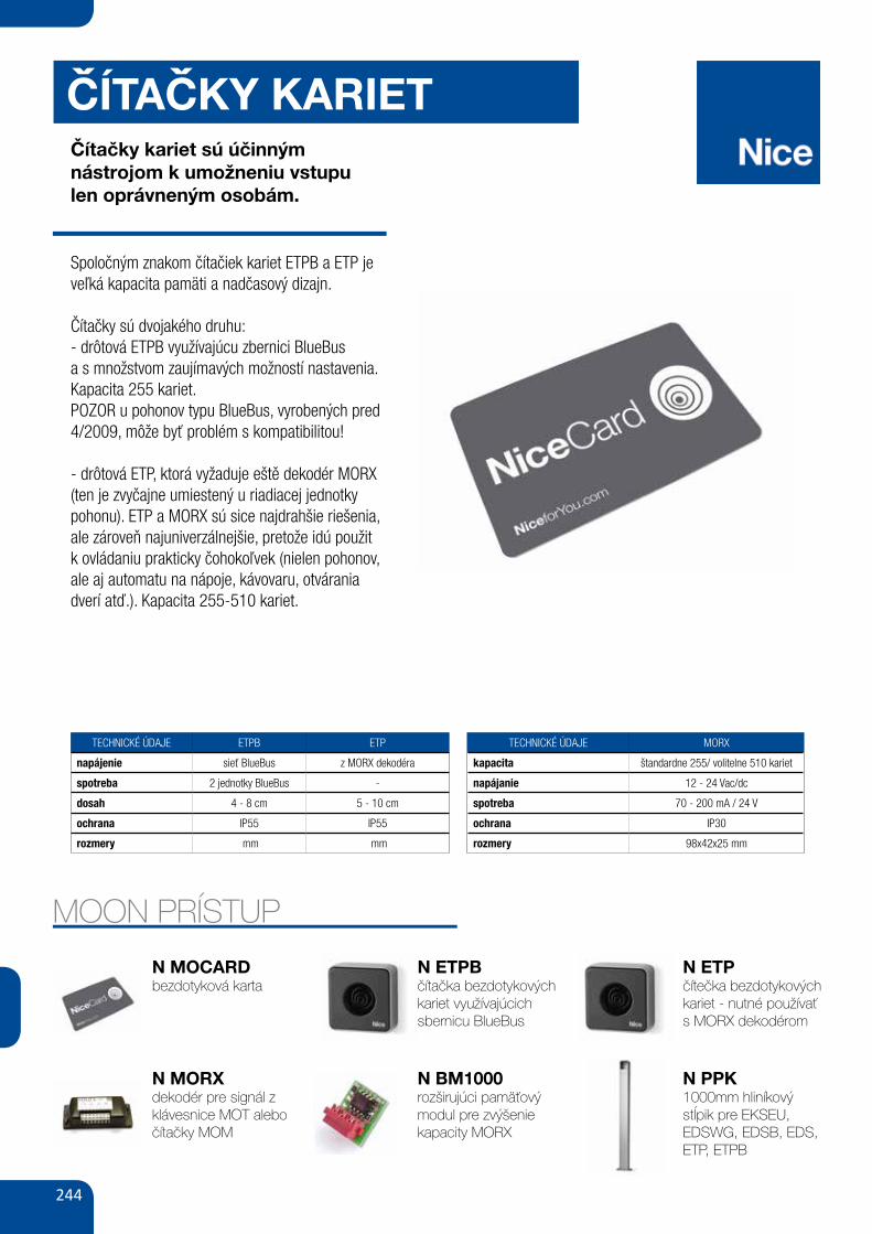
244
CÍTACKY KARIETČítačky kariet sú účinnýmnástrojom k umožneniu vstupulen oprávneným osobám.
Spoločným znakom čítačiek kariet ETPB a ETP je veľká kapacita pamäti a nadčasový dizajn.
Čítačky sú dvojakého druhu:- drôtová ETPB využívajúcu zbernici BlueBusa s množstvom zaujímavých možností nastavenia. Kapacita 255 kariet.POZOR u pohonov typu BlueBus, vyrobených pred 4/2009, môže byť problém s kompatibilitou!
- drôtová ETP, ktorá vyžaduje eště dekodér MORX (ten je zvyčajne umiestený u riadiacej jednotky pohonu). ETP a MORX sú sice najdrahšie riešenia, ale zároveň najuniverzálnejšie, pretože idú použit k ovládaniu prakticky čohokoľvek (nielen pohonov, ale aj automatu na nápoje, kávovaru, otvárania dverí atď.). Kapacita 255-510 kariet.
MOON PRÍSTUP
N MOCARDbezdotyková karta
N MORXdekodér pre signál z klávesnice MOT alebo čítačky MOM
N ETPBčítačka bezdotykových kariet využívajúcich sbernicu BlueBus
N BM1000rozširujúci pamäťový modul pre zvýšenie kapacity MORX
N ETPčítečka bezdotykových kariet - nutné používaťs MORX dekodérom
TECHNICKÉ ÚDAJE ETPB ETP
napájenie sieť BlueBus z MORX dekodéra
spotreba 2 jednotky BlueBus -
dosah 4 - 8 cm 5 - 10 cm
ochrana IP55 IP55
rozmery mm mm
ˇ
TECHNICKÉ ÚDAJE MORX
kapacita štandardne 255/ volitelne 510 kariet
napájanie 12 - 24 Vac/dc
spotreba 70 - 200 mA / 24 V
ochrana IP30
rozmery 98x42x25 mm
ˇ
N PPK1000mm hliníkový stĺpik pre EKSEU, EDSWG, EDSB, EDS, ETP, ETPB
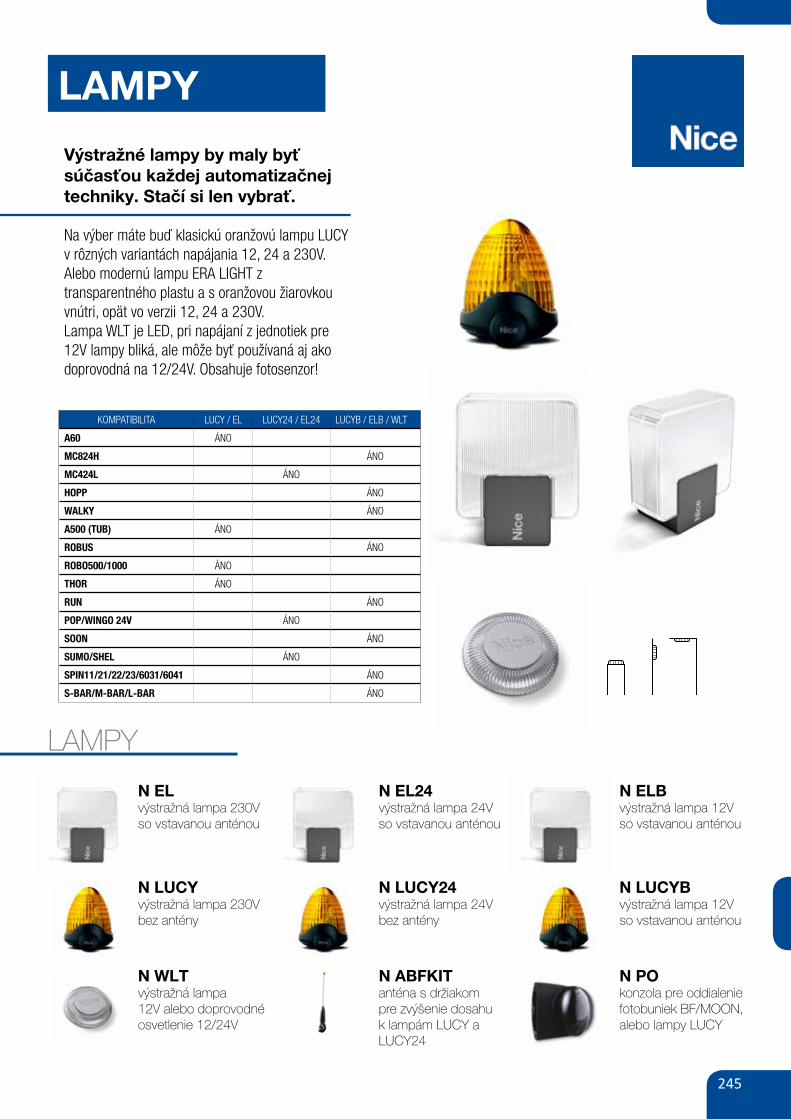
245
LAMPY
Výstražné lampy by maly byť súčasťou každej automatizačnej techniky. Stačí si len vybrať.
Na výber máte buď klasickú oranžovú lampu LUCY v rôzných variantách napájania 12, 24 a 230V.Alebo modernú lampu ERA LIGHT ztransparentného plastu a s oranžovou žiarovkou vnútri, opät vo verzii 12, 24 a 230V.Lampa WLT je LED, pri napájaní z jednotiek pre12V lampy bliká, ale môže byť používaná aj ako doprovodná na 12/24V. Obsahuje fotosenzor!
LAMPY
N ELvýstražná lampa 230V so vstavanou anténou
N LUCYvýstražná lampa 230Vbez antény
N EL24výstražná lampa 24Vso vstavanou anténou
N LUCY24výstražná lampa 24Vbez antény
N ELBvýstražná lampa 12Vso vstavanou anténou
N LUCYB výstražná lampa 12Vso vstavanou anténou
N WLTvýstražná lampa12V alebo doprovodné osvetlenie 12/24V
N ABFKITanténa s držiakom pre zvýšenie dosahu k lampám LUCY a LUCY24
N POkonzola pre oddialenie fotobuniek BF/MOON, alebo lampy LUCY
KOMPATIBILITA LUCY / EL LUCY24 / EL24 LUCYB / ELB / WLT
A60 ÁNO
MC824H ÁNO
MC424L ÁNO
HOPP ÁNO
WALKY ÁNO
A500 (TUB) ÁNO
ROBUS ÁNO
ROBO500/1000 ÁNO
THOR ÁNO
RUN ÁNO
POP/WINGO 24V ÁNO
SOON ÁNO
SUMO/SHEL ÁNO
SPIN11/21/22/23/6031/6041 ÁNO
S-BAR/M-BAR/L-BAR ÁNO
187
WALLyGhT
A924
mC82
4hmC
424L
WALk
yPO
Phy
kERO
ADRO
bus
RuN
NAkE
D sL
IDIN
G 40
0sP
IN /
sPIN
bus
sPID
ER /
sPID
OTE
NsO
ONs/
m/L
bAR
sIGN
OW
IL
WLT • • • • • • • • • • • • • • • • •
WALLyGhT Accessories
multi-function LED indicator.
The only version with 12/24 Vac/Vdc power supply and flashing light function, courtesy light function or dusk sensor function.
A new idea for improved safety: when connected to compatible control units, Wallyght can act as a normal flashing light, or provide ambient lighting like a fixed courtesy light. When connected to a 12/24 Vac/Vdc output, Wallyght can remain permanently lit, and also be activated at dusk to then turn off at dawn thanks to the integrated dusk sensor.
Optimal efficiency, extra long life: the two 1 W-Leds guarantee a lifetime of 70.000 hours (continuous use).
horizontal, wall or ceiling mounting: combined with the possibility of orienting the light beam and compact dimensions of the IP44 box, use of Wallyght is even more flexible.
CODE DESCRIPTION PC/PACK
WLT MULTI-FUNCTION LED INDICATOR 1
COmPATIbILITy TAbLE
PATh INDICATORs ON ENTRANCE PAThWAys COuRTEsy LIGhT
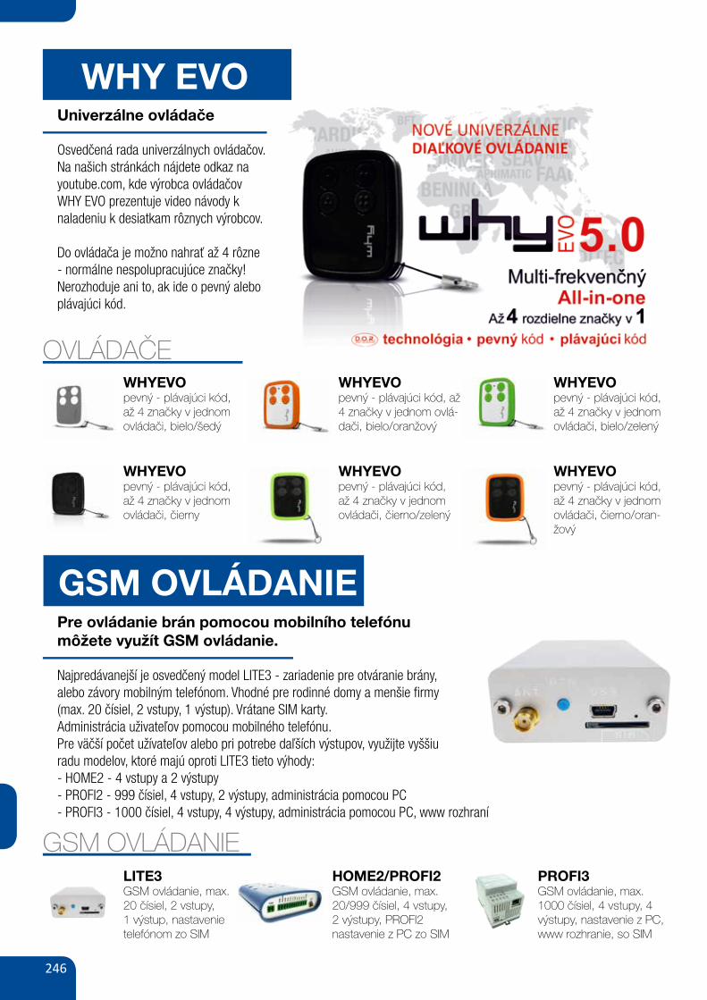
246
WHY EVOUniverzálne ovládače
Osvedčená rada univerzálnych ovládačov. Na našich stránkách nájdete odkaz na youtube.com, kde výrobca ovládačov WHY EVO prezentuje video návody k naladeniu k desiatkam rôznych výrobcov.
Do ovládača je možno nahrať až 4 rôzne - normálne nespolupracujúce značky!Nerozhoduje ani to, ak ide o pevný alebo plávajúci kód.
OVLÁDAČEWHYEVOpevný - plávajúci kód, až 4 značky v jednom ovládači, bielo/šedý
WHYEVOpevný - plávajúci kód, až 4 značky v jednom ovládači, čierny
WHYEVOpevný - plávajúci kód, až 4 značky v jednom ovlá-dači, bielo/oranžový
WHYEVOpevný - plávajúci kód, až 4 značky v jednom ovládači, čierno/zelený
WHYEVOpevný - plávajúci kód, až 4 značky v jednom ovládači, bielo/zelený
WHYEVOpevný - plávajúci kód, až 4 značky v jednom ovládači, čierno/oran-žový
GSM OVLÁDANIEPre ovládanie brán pomocou mobilního telefónumôžete využít GSM ovládanie.
Najpredávanejší je osvedčený model LITE3 - zariadenie pre otváranie brány,alebo závory mobilným telefónom. Vhodné pre rodinné domy a menšie firmy(max. 20 čísiel, 2 vstupy, 1 výstup). Vrátane SIM karty.Administrácia uživateľov pomocou mobilného telefónu.Pre väčší počet užívateľov alebo pri potrebe daľších výstupov, využijte vyššiuradu modelov, ktoré majú oproti LITE3 tieto výhody:- HOME2 - 4 vstupy a 2 výstupy- PROFI2 - 999 čísiel, 4 vstupy, 2 výstupy, administrácia pomocou PC- PROFI3 - 1000 čísiel, 4 vstupy, 4 výstupy, administrácia pomocou PC, www rozhraní
GSM OVLÁDANIELITE3GSM ovládanie, max. 20 čísiel, 2 vstupy, 1 výstup, nastavenie telefónom zo SIM
HOME2/PROFI2GSM ovládanie, max. 20/999 čísiel, 4 vstupy, 2 výstupy, PROFI2nastavenie z PC zo SIM
PROFI3GSM ovládanie, max. 1000 čísiel, 4 vstupy, 4 výstupy, nastavenie z PC, www rozhranie, so SIM
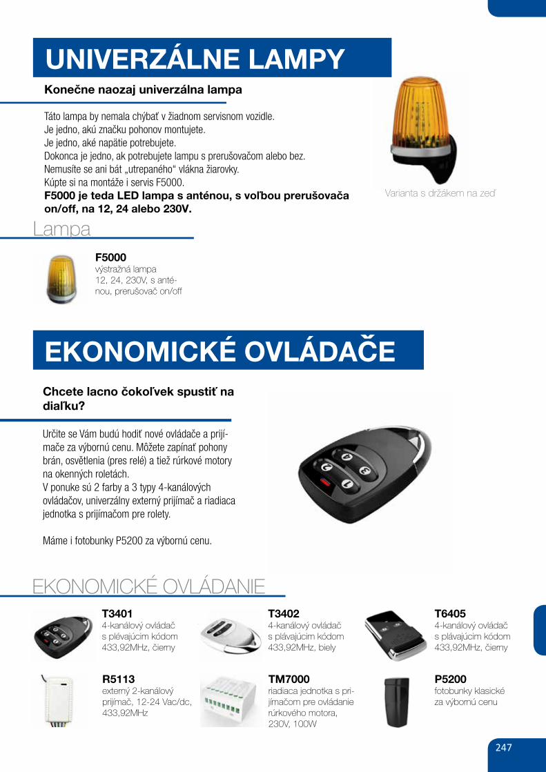
247
EKONOMICKÉ OVLÁDACEChcete lacno čokoľvek spustiť na diaľku?
Určite se Vám budú hodiť nové ovládače a prijí-mače za výbornú cenu. Môžete zapínať pohony brán, osvětlenia (pres relé) a tiež rúrkové motory na okenných roletách.V ponuke sú 2 farby a 3 typy 4-kanálových ovládačov, univerzálny externý prijímač a riadiaca jednotka s prijímačom pre rolety.
Máme i fotobunky P5200 za výbornú cenu.
EKONOMICKÉ OVLÁDANIE
UNIVERZÁLNE LAMPYKonečne naozaj univerzálna lampa
Táto lampa by nemala chýbať v žiadnom servisnom vozidle.Je jedno, akú značku pohonov montujete.Je jedno, aké napätie potrebujete.Dokonca je jedno, ak potrebujete lampu s prerušovačom alebo bez.Nemusíte se ani bát „utrepaného“ vlákna žiarovky.Kúpte si na montáže i servis F5000.F5000 je teda LED lampa s anténou, s voľbou prerušovačaon/off, na 12, 24 alebo 230V.
LampaF5000výstražná lampa12, 24, 230V, s anté-nou, prerušovač on/off
R5113externý 2-kanálový prijímač, 12-24 Vac/dc, 433,92MHz
T34014-kanálový ovládač s plévajúcim kódom 433,92MHz, čierny
TM7000riadiaca jednotka s pri-jímačom pre ovládanie rúrkového motora,230V, 100W
T34024-kanálový ovládač s plávajúcim kódom 433,92MHz, biely
T64054-kanálový ovládač s plávajúcim kódom 433,92MHz, čierny
ˇ
58 GATE&DOOR 2013
≥ 130
≥ 300
B ≥ 710 mmA ≥ 450
B ≤
450
A ≤
350
hyPPO 7000
800
700
600
500
400
300
2002 2,5 3
HY7005
HY7005 / HY7024
165350 mm
242
9015
2
230V24VbLuEbusOPERAsOLEmyO
hy7024 hy7005
- 23024 -5 1.2
120 250
2 1.7250 40080 30
43-20 ÷ +50
350x165x242 h13
For swing gates with leaves up to 3 m, also ideal for large pillars. Electromechanical gear motor, surface mounted, also in 24 Vdc version with magnetic encoder, with articulated arm.
Single model for right and left leaves. Two irreversible versions, with 230 Vac (HY7005) and 24 Vdc (HY7024) power supplies with magnetic encoder.
Fewer connections mean quicker installation.
Pre-wired, incorporated double limit-switch both during opening and closing (HY7005).
mAx
. GAT
E W
EIGh
T (k
G)
mAx. GATE LENGTh (m)
N.B. The above values are valid if the motor is used with standard accessories. The shape, the height of the gate and the weather conditions can considerably reduce the values shown in the graph to the side. Use in windy areas 230 Vac models.
CODE DESCRIPTION PACK/PALLET
hy7024 IRREVERSIBLE, 24 Vdc, WITH MAGNETIC ENCODER, WITH SHEAR-PROOF ARTICULATED ARM, GALVANIZED AND PAINTED
16
hy7005 IRREVERSIBLE, 230 Vac, WITH STURDY ARTICULATED SHEAR-PROOF ARM, GALVANIZED AND PAINTED, WITH LIMIT SWITCH ON OPENING AND CLOSING
16
Easy and quick to install: thanks to fewer connections and nothing welded to the gates.
Long-lasting: solid metal mechanics.
Compact: shockproof bodywork with no sharp corners.
Recommended control units: Mindy A6F, A60, A700F; for HY7024 Moonclever MC824H.
24 Vdc version with magnetic encoder. Perfect for intensive use, compatible with the control unit Moonclever MC824H: • simple programming, by means of a single key; • self-learning of opening and closing limit positions; • automatic fault diagnostics; • programming of pause time; • pedestrian pass door; • deceleration on opening and closing; • obstacle detection with dual technology; • operation in event of power failure by means of optional rechargeable batteries (PS324); • provision for connection of latest generation resistive sensitive edges.
TEChNICAL sPECIFICATIONsCODEELECTRICAL DATAPOWER SUPPLY (Vac 50 Hz)*POWER SUPPLY (Vdc)ABSORPTION (A)POWER (W)PERFORmANCE DATASPEED (rpm)TORqUE (Nm)WORK CYCLE (%)DImENsIONAL AND GENERAL DATAPROTECTION LEVEL (IP)WORKING TEMP. (°C MIN/MAx)DIMENSIONS (mm)WEIGHT (kg)
*60 Hz version available on request.
A Standard armb Arm with accessory HYA12
uTILIsATION LImITs DImENsIONs
STURDY, ANTI-SHEARING ARM, GALVANISED AND PAINTED; STRENGTHENED IN THOSE AREAS SUBjECTED TO GREATER MECHANICAL STRESS
DIE-CAST, ALUMINIUM, KEY-OPERATED UNLOCK SYSTEM, COMPLETE WITH PROTECTED KEY. DESIGNED TO ACCOMMODATE ExTERNAL RELEASE, TOO
P5200fotobunky klasickéza výbornú cenu
Varianta s držákem na zeď


![アキレス株式会社 [Achilles] | トップ...SK-150 SK-151 01645rB/rå 31 SK-47 SK-150 SK-151 SK-85 32 : SK-410 (M*ã) SK-37 Y SK-111A.B[bø 39 SK-103A • B SK—IOI V 300R SK-69](https://static.fdocuments.pl/doc/165x107/6129a1d73d37b20602014f9a/fc-achilles-ffff-sk-150-sk-151-01645rbr-31.jpg)