
J. MICHALCZYK - Instytut Metalurgii i Inżynierii …imim.pl/files/archiwum/Vol2_2011/34.pdf ·...
9
A R C H I V E S O F M E T A L L U R G Y A N D M A T E R I A L S Volume 56 2011 Issue 2 DOI: 10.2478/v10172-011-0057-1 J. MICHALCZYK * , T. BAJOR * STUDY ON THE INFLUENCE OF TEMPERATURE, VELOCITY AND SHAPE OF TOOLS ON THE COMBINED PROCESS OF EXTRUSION AND BROACHING OF THE DEEP SLEEVE WITH THE BOTTOM MADE OF THE AZ31 ALLOY BADANIE WPLYWU KSZTALTU NARZĘDZI I PARAMETRÓW TEMPERATUROWO – PRĘDKOŚCIOWYCH NA PROCES POLĄCZONEGO WYCISKANIA I PRZECIĄGANIA TULEI GLĘBOKICH Z DNEM ZE STOPU AZ31 The article presents the results of a theoretical analysis of the manufacturing process of the deep sleeve with the bottom by means of a method of combining the indirect extrusion of a thick bush and broaching the blank through the conical die in one cycle of the stamp. The main advantage of application of the developed method for production of the sleeve is to reduce demand for energy and force compared to traditional methods of producing the deep sleeve. Moreover, the nature of the single operation of the extrusion process and extension of the sleeve eliminates the necessity of additional treatments: soft annealing, reheating the charge and reducing wall thickness of the sleeve by a second tool, which significantly reduce energy, labour and time consumption of production. Numerical calculations were performed in the Forge R 2D using plane state of strain and the obtained results allowed to determine the forces necessary for the process and the strain limit, as well as die geometry and impact velocity on the process tool. Keywords: complex extrusion, new method extrusion deep sleeves W artykule przedstawiono wyniki z teoretycznej analizy procesu wytwarzania tulei glębokich z dnem z zastosowaniem metody polegającej na polączeniu wyciskania przeciwbieżnego grubościennej tulei i przeciągania pólwyrobu przez matrycę stożkową w jednym cyklu posuwu stempla. Zasadniczą korzyścią z zastosowania opracowanego sposobu wytwarzania tulei jest obniżenie zapotrzebowania na parametry energetyczno – silowe w stosunku do tradycyjnych metod wytwarzania tulei glębokich. Ponadto jednooperacyjny charakter procesu wyciskania i wydlużania tulei pozwala na wyeliminowanie konieczności dodatkowych zabiegów: wyżarzania zmiękczającego lub dogrzewania wsadu oraz redukowania grubości ścianki tulei w drugim narzędziu przez, co ograniczy w znaczący sposób zużycie energii, pracochlonność i czasochlonność produkcji. Obliczenia numeryczne wykonano w programie Forge R 2D stosując plaski stan odksztalceń a uzyskane wyniki pozwolily na określenie sil niezbędnych do przeprowadzenia procesu oraz określenie granicznej wartości zadawanych odksztalceń, geometrii matrycy i wplywu prędkości narzędzi na przebieg procesu. 1. Introduction Application of high values of the total strain dur- ing forming processes increases the demand for energy and force in the whole manufacturing process. This ap- plies especially to the deep hollow extrusion of products, in particular ones with a complicated cross-sectional shape. Therefore, the design of extrusion process tech- nology is an important issue to minimize the energy and force parameters. There are many methods to reduce the strength indicators processes by selecting appropriate pa- rameters, e. g.: properties of extruded material, degree of processing and elongation factor, velocity of the extru- sion process, initial temperature of the charge, prepara- tion of the charge, lubrication and structure and shape of the matrix. As it is presented in [6], a very effective method of reducing energy and force parameters of extrusion process is joining the patterns of metal flow and the distribution of a stream of the metal flow in such a way, that local increases in temperature in the first phase of the process will appear exactly in the places where, the greatest plastic deformation is observed in the second phase. During the indirect extrusion, the working tools are subjected to the highest stress in the third phase of process [2], during the formation of the bottom. This phase in industrial practice is usually ignored, but as * CZĘSTOCHOWA UNIVERSITY OF TECHNOLOGY, FACULTY OF MATERIAL PROCESSING TECHNOLOGY AND APPLIED PHYSICS, INSTITUTE OF MODELLING AND AUTOMATION OF PLASTIC WORKING PROCESSES, 42-200 CZĘSTOCHOWA, 19 ARMII KRAJOWEJ STR., POLAND
Transcript of J. MICHALCZYK - Instytut Metalurgii i Inżynierii …imim.pl/files/archiwum/Vol2_2011/34.pdf ·...

A R C H I V E S O F M E T A L L U R G Y A N D M A T E R I A L S
Volume 56 2011 Issue 2
DOI: 10.2478/v10172-011-0057-1
J. MICHALCZYK∗, T. BAJOR∗
STUDY ON THE INFLUENCE OF TEMPERATURE, VELOCITY AND SHAPE OF TOOLS ON THE COMBINED PROCESS OFEXTRUSION AND BROACHING OF THE DEEP SLEEVE WITH THE BOTTOM MADE OF THE AZ31 ALLOY
BADANIE WPŁYWU KSZTAŁTU NARZĘDZI I PARAMETRÓW TEMPERATUROWO – PRĘDKOŚCIOWYCH NA PROCESPOŁĄCZONEGO WYCISKANIA I PRZECIĄGANIA TULEI GŁĘBOKICH Z DNEM ZE STOPU AZ31
The article presents the results of a theoretical analysis of the manufacturing process of the deep sleeve with the bottomby means of a method of combining the indirect extrusion of a thick bush and broaching the blank through the conical die inone cycle of the stamp. The main advantage of application of the developed method for production of the sleeve is to reducedemand for energy and force compared to traditional methods of producing the deep sleeve. Moreover, the nature of the singleoperation of the extrusion process and extension of the sleeve eliminates the necessity of additional treatments: soft annealing,reheating the charge and reducing wall thickness of the sleeve by a second tool, which significantly reduce energy, labour andtime consumption of production. Numerical calculations were performed in the Forge R© 2D using plane state of strain andthe obtained results allowed to determine the forces necessary for the process and the strain limit, as well as die geometry andimpact velocity on the process tool.
Keywords: complex extrusion, new method extrusion deep sleeves
W artykule przedstawiono wyniki z teoretycznej analizy procesu wytwarzania tulei głębokich z dnem z zastosowaniemmetody polegającej na połączeniu wyciskania przeciwbieżnego grubościennej tulei i przeciągania półwyrobu przez matrycęstożkową w jednym cyklu posuwu stempla. Zasadniczą korzyścią z zastosowania opracowanego sposobu wytwarzania tuleijest obniżenie zapotrzebowania na parametry energetyczno – siłowe w stosunku do tradycyjnych metod wytwarzania tuleigłębokich. Ponadto jednooperacyjny charakter procesu wyciskania i wydłużania tulei pozwala na wyeliminowanie koniecznościdodatkowych zabiegów: wyżarzania zmiękczającego lub dogrzewania wsadu oraz redukowania grubości ścianki tulei w drugimnarzędziu przez, co ograniczy w znaczący sposób zużycie energii, pracochłonność i czasochłonność produkcji. Obliczenianumeryczne wykonano w programie Forge R©2D stosując płaski stan odkształceń a uzyskane wyniki pozwoliły na określeniesił niezbędnych do przeprowadzenia procesu oraz określenie granicznej wartości zadawanych odkształceń, geometrii matrycyi wpływu prędkości narzędzi na przebieg procesu.
1. Introduction
Application of high values of the total strain dur-ing forming processes increases the demand for energyand force in the whole manufacturing process. This ap-plies especially to the deep hollow extrusion of products,in particular ones with a complicated cross-sectionalshape. Therefore, the design of extrusion process tech-nology is an important issue to minimize the energy andforce parameters. There are many methods to reduce thestrength indicators processes by selecting appropriate pa-rameters, e.g.: properties of extruded material, degree ofprocessing and elongation factor, velocity of the extru-sion process, initial temperature of the charge, prepara-
tion of the charge, lubrication and structure and shapeof the matrix.
As it is presented in [6], a very effective methodof reducing energy and force parameters of extrusionprocess is joining the patterns of metal flow and thedistribution of a stream of the metal flow in such a way,that local increases in temperature in the first phase ofthe process will appear exactly in the places where, thegreatest plastic deformation is observed in the secondphase.
During the indirect extrusion, the working tools aresubjected to the highest stress in the third phase ofprocess [2], during the formation of the bottom. Thisphase in industrial practice is usually ignored, but as
∗ CZĘSTOCHOWA UNIVERSITY OF TECHNOLOGY, FACULTY OF MATERIAL PROCESSING TECHNOLOGY AND APPLIED PHYSICS, INSTITUTE OF MODELLING AND AUTOMATION OFPLASTIC WORKING PROCESSES, 42-200 CZĘSTOCHOWA, 19 ARMII KRAJOWEJ STR., POLAND

534
shown by results in [7], the extrusion force in relation tothe value of the first phase of the process, where the riseuntil it reaches a local maximum is noted, increases by15 to 20%. In extrusion processes of the deep products,where the total hight of the product exceeds 2.5-fold itsinternal diameter, the tools (stamp and matrix) work athigh temperatures and large long-term burden. To pro-duce the deep sleeves on a massive scale using the con-ventional coextrusion method, the interoperational heattreatment should be applied, or alternatively additionalheating of the charge, and complete the operation processunder a separate finishing tool.
This paper presents an analysis of manufacturingof the deep sleeve by combination of the process-es: concurrent extrusion of thick sleeve and broachingthe blank through a conical die. Preliminary numer-ical studies have shown that demand for energy andforce in the whole process are lower than in the con-ventional processes of producing the deep sleeve. Anenergy-consumption indicator of the process, which wasthe average force of extrusion of the whole process wasreduced by about 35%.
The numerical study involved an analysis of the im-pact of variables such as:• initial temperature of the charge (T0 = 300, 350,
400 [◦C]);• feed speed of a punch (V = 25, 50, 100 [mm / s]);• degree of strain (ε = 0.3);• angle of the conical die (α = 10◦, 12◦, 15◦)on the combined process of extrusion and drawing ofthe sleeve.
The model material for the study was the AZ31alloy. The characteristics of the material needed forthe equations determining the values of flow stress byForge R© software were obtained in plastometric testsperformed at Gleeble 3800 system.
2. The concept of a new method of deep sleeveproduction
The deep sleeves are products used in metallurgi-cal, machinery, aerospace, automotive and defense in-dustry. They can be used as semi-finished products forthe further production of pipes, manufacture of hydrauliccylinders, construction machinery parts, shells and bul-lets casings of medium and large caliber.
By definition, these are products characterized bythe ratio of the total height Ht to the dimensionof inner diameter Dw is greater than or equal to2.5.(Hc/Dw > 2.5).
In papers [4,6] the results of newly developed waysof extrusion of the deep sleeve from a whole charge arepresented. They ensure completion of the process in onetechnological process by reducing the extrusion force by40% as compared to the indirect extrusion. Moreover,substantial increase in strength/force during the forma-tion of the bottom of the sleeve was eliminated. However,the proposed scheme of the metal flow in the describedmethod make it necessary to design a tool with a rathercomplicated operational scheme [7].
Fig. 1. The product deep sleeve, where: Hc – total height, Dw –internal diameter, Dz – outside diameter
To produce such products without the need for ad-ditional operations listed in Introduction, and use sim-ple assembly of the working tools, the authors pro-posed a new way of combining manufacturing extru-sion and drawing the sleeve in one technological treat-ment/process. A scheme of the process is shown in Fig-ure 1.
The process is basically divided into two stages. Thefirst stage of the process of the indirect extrusion of arelatively shallow thick sleeve from a rolled charge (2)in a container (1) is by an action of the stamp (3). Whenthe face of the stamp (3) reaches a distance from theface of the ejector (5) equal to the assumed thickness ofthe bottom of the sleeve, the second stage of the processbegins, where both the punch (3) and holes (2) are mov-ing in the same direction, with the same constant speedwithout changing the distance between them [3].

535
Fig. 2. Scheme of the process connected extraction and dragging the sleeve deep. 1) the container to the matrix 2) charge, 3) punch, 4)guide. a) the initial state of the process, b) Stage I c) Stage II
3. The material used in the studies
The model material used in numerical studies wasmagnesium alloy AZ31 with the chemical compositiongiven in Table 1. The alloy was used for pressing as wellas hot and warm extrusion [1].
TABLE 1The chemical composition of the tested alloy
Gradealloy
The content of ingredients, %
Mg Al Mn Nd Sb Zn Fe Si
AZ31 96.284 2.58 0.12 0.005 0.017 0.99 0.002 0.02
To determine the rheological properties of the al-loy and to generate the coefficients of the equation,which is used by the numerical program to determinethe flow stress, the tests were performed at GLEEBLE3800 physical simulation system. Figure 3 shows com-pression characteristics of the samples at temperaturesof 200, 300 and 400◦C and strain rates of 0.1, 1, 10 s−1.
Fig. 3. The curves of strengthening obtained in studies on the GLEE-BLE 3800 system
After approximation of specified/obtained? data, thecoefficients nap the equation were determined:
σp = Aem1·t · εm2 · em4·εε̇m3 (1)
where: σp – flow stressA, m1, m2, m3, m4 - coefficientshave value:A = 2624.315, m1= -0.00475, m2= -011510, m3=
0.18406, m4= - 0.00964
536
4. Experimental method and assumptions forcomputer simulation
Process of theoretical analysis was carried out basedon the results obtained from computer simulations per-formed by means of Forge R© software. Due to the na-ture of the axially-symmetric process, calculations werecarried out for a flat state of deformation. Two-step na-ture of the process requires application of the programfunction Multistep, which transport data from the lastcomputational step of the first stage of the process tothe first computational step in the second stage of theprocess. Thanks to this calculation in the second stageof the process conditions include temperature-velocityconditions and energy-force parameters present in thefirst stage of the process.
The main variable parameters in the process werethe initial temperature T0 of feed, cone angle of the dieα, through which the semi-finished product was drawn inthe first stage of the process, and the speed of extrusionand broaching.
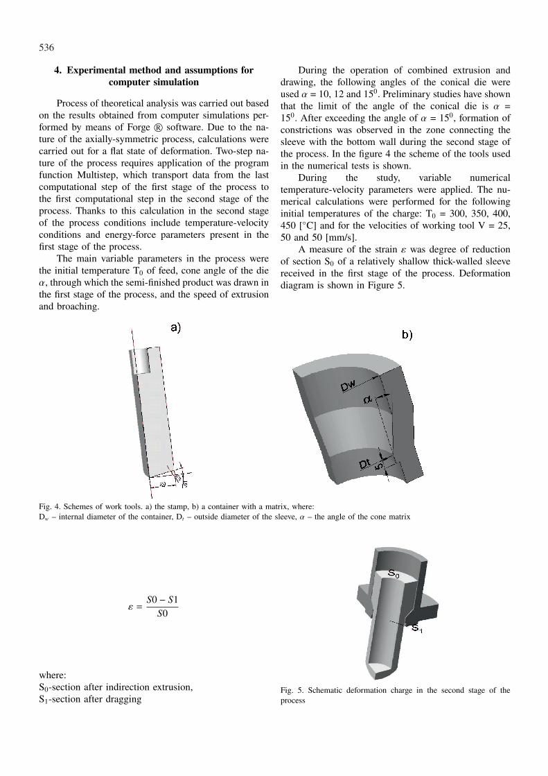
During the operation of combined extrusion anddrawing, the following angles of the conical die wereused α = 10, 12 and 150. Preliminary studies have shownthat the limit of the angle of the conical die is α =150. After exceeding the angle of α = 150, formation ofconstrictions was observed in the zone connecting thesleeve with the bottom wall during the second stage ofthe process. In the figure 4 the scheme of the tools usedin the numerical tests is shown.
During the study, variable numericaltemperature-velocity parameters were applied. The nu-merical calculations were performed for the followinginitial temperatures of the charge: T0 = 300, 350, 400,450 [◦C] and for the velocities of working tool V = 25,50 and 50 [mm/s].
A measure of the strain ε was degree of reductionof section S0 of a relatively shallow thick-walled sleevereceived in the first stage of the process. Deformationdiagram is shown in Figure 5.
Fig. 4. Schemes of work tools. a) the stamp, b) a container with a matrix, where:Dw – internal diameter of the container, Dt – outside diameter of the sleeve, α – the angle of the cone matrix
ε =S0 − S1
S0
where:S0-section after indirection extrusion,S1-section after dragging
Fig. 5. Schematic deformation charge in the second stage of theprocess
537
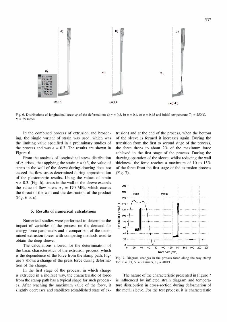
Fig. 6. Distributions of longitudinal stress σ of the deformation: a) ε = 0.3, b) ε = 0.4, c) ε = 0.45 and initial temperature T0 = 250◦C,V = 25 mm/s
In the combined process of extrusion and broach-ing, the single variant of strain was used, which wasthe limiting value specified in a preliminary studies ofthe process and was ε = 0.3. The results are shown inFigure 6.
From the analysis of longitudinal stress distributionof σ arises, that applying the strain ε = 0.3, the value ofstress in the wall of the sleeve during drawing does notexceed the flow stress determined during approximationof the plastometric results. Using the values of strainε > 0.3. (Fig. 6), stress in the wall of the sleeve exceedsthe value of flow stress σp = 170 MPa, which causesthe throat of the wall and the destruction of the product(Fig. 6 b, c).
5. Results of numerical calculations
Numerical studies were performed to determine theimpact of variables of the process on the demand forenergy-force parameters and a comparison of the deter-mined extrusion forces with competing methods used toobtain the deep sleeve.
The calculations allowed for the determination ofthe basic characteristics of the extrusion process, whichis the dependence of the force from the stamp path. Fig-ure 7 shows a change of the press force during deforma-tion of the charge.
In the first stage of the process, in which chargeis extruded in a indirect way, the characteristic of forcefrom the stamp path has a typical shape for such process-es. After reaching the maximum value of the force, itslightly decreases and stabilizes (established state of ex-
trusion) and at the end of the process, when the bottomof the sleeve is formed it increases again. During thetransition from the first to second stage of the process,the force drops to about 2% of the maximum forceachieved in the first stage of the process. During thedrawing operation of the sleeve, whilst reducing the wallthickness, the force reaches a maximum of 10 to 15%of the force from the first stage of the extrusion process(Fig. 7).
Fig. 7. Diagram changes in the presses force along the way stampfor: ε = 0.3, V = 25 mm/s, T0 = 400◦C
The nature of the characteristic presented in Figure 7is influenced by inflicted strain diagram and tempera-ture distribution in cross-section during deformation ofthe metal sleeve. For the test process, it is characteristic

538
that in the first stage of the extrusion, the greatest localtemperature increments exist in the wall of the sleeve.This is an area where during the second stage the largestamount of plastic deformation takes place, which allows
to impose a relatively large strain without losing the con-sistency of the material. Characteristic distributions ofthe temperature and impact velocity of the process isshown in Figure 8.
Fig. 8. The temperature distribution for the parameters: ε = 0.3, T0 = 300◦C and V = 25, 50, 100 mm/s
Fig. 9. Effect of feed rate stamp on the strength of the pressure press for V = 25, 50, 100 mm/s, T0 = 300, 350, 400, 450◦C. a) stage I andII, b) Stage I, c) Stage II
539
As is apparent from the temperature distributions asignificant impact on the process in the second stage isto speed extrusion. Threefold increase in speed causesan increase in temperature in the wall of the sleeve in thefirst stage by about 25% compared to the lowest speedV = 25 mm/s. Similar proportions of temperature in-crease occur in the second stage of process (Figure 8).
Figure 9 shows the impact of feed speed gear in thepressure-press based on surface graphs.
From the graphs presented in Figure 9a shows, thatincreasing the tool feed speed from 25 to 100 mm/s inthe whole range of average temperatures will increase thepress force of about 10 to 15%. It is particularly evidentin the first stage of process (Figure 9b), in the processof indirect extrusion, and the reason is the strengtheningof the metal under the stamp. For higher temperaturesthe increase in pressure is less, which is a consequenceof the lower value of σp In the second stage of processthe growth of the press force is the lowest temperature(Fig. 9c). For other variants of T0 at each value of Vmean force, the press is on the same level and at thehighest T0 shows a downward trend. A clear advantageof the temperature effect and the imposition of zones ofdeformation of the first stage, where he experienced thegreatest increases in local temperature are the causes ofdecline in energy – force parameters in the second stageof the process.
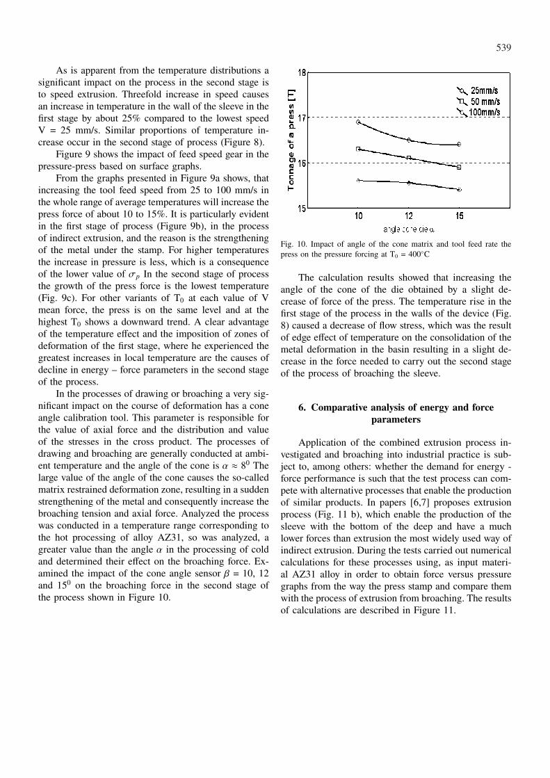
In the processes of drawing or broaching a very sig-nificant impact on the course of deformation has a coneangle calibration tool. This parameter is responsible forthe value of axial force and the distribution and valueof the stresses in the cross product. The processes ofdrawing and broaching are generally conducted at ambi-ent temperature and the angle of the cone is α ≈ 80 Thelarge value of the angle of the cone causes the so-calledmatrix restrained deformation zone, resulting in a suddenstrengthening of the metal and consequently increase thebroaching tension and axial force. Analyzed the processwas conducted in a temperature range corresponding tothe hot processing of alloy AZ31, so was analyzed, agreater value than the angle α in the processing of coldand determined their effect on the broaching force. Ex-amined the impact of the cone angle sensor β = 10, 12and 150 on the broaching force in the second stage ofthe process shown in Figure 10.
Fig. 10. Impact of angle of the cone matrix and tool feed rate thepress on the pressure forcing at T0 = 400◦C
The calculation results showed that increasing theangle of the cone of the die obtained by a slight de-crease of force of the press. The temperature rise in thefirst stage of the process in the walls of the device (Fig.8) caused a decrease of flow stress, which was the resultof edge effect of temperature on the consolidation of themetal deformation in the basin resulting in a slight de-crease in the force needed to carry out the second stageof the process of broaching the sleeve.
6. Comparative analysis of energy and forceparameters
Application of the combined extrusion process in-vestigated and broaching into industrial practice is sub-ject to, among others: whether the demand for energy -force performance is such that the test process can com-pete with alternative processes that enable the productionof similar products. In papers [6,7] proposes extrusionprocess (Fig. 11 b), which enable the production of thesleeve with the bottom of the deep and have a muchlower forces than extrusion the most widely used way ofindirect extrusion. During the tests carried out numericalcalculations for these processes using, as input materi-al AZ31 alloy in order to obtain force versus pressuregraphs from the way the press stamp and compare themwith the process of extrusion from broaching. The resultsof calculations are described in Figure 11.

540
Fig. 11. Diagrams force changes in the way the press stamp for V = 25 mm/s, T0 = 350◦C: a) extrusion complex, b) two-sided complexextrusion, c) indirect extrusion
A measure of energy consumption in the manufac-turing process is the average force of extrusion, whichtakes into account the force of the process from be-ginning to end. Numerical calculations showed that themean force, press the test combined extrusion processwith broaching at T0 = 3500C and V = 25 mm/s was135 Tons. The results of calculations for the alterna-tive processes for manufacturing the sleeve shown inFigure 11 were: complex extrusion (Fig. 11a) 121 Ton,two-sided extrusion complex (Fig. 11b) 130 Ton, indirectextrusion (Fig. 11c) 165 Ton.
7. Conclusion
The results shown in this study suggest that it ispossible to carry out two-stage combined extrusion andbroaching in one treatment technology, without movingthe blank to the second gear after the first step to com-plete the operation by broaching the sleeve. As shownthe numerical calculations of the demand for energy –force of parameters of the test process relative to com-peting methods of extrusion, which significantly exceed
the indirect extrusion the sleeve is at a similar level. Theenergy intensity of the process, which is the averageforce, the press has been reduced thanks to the work ofthe proposed process for the manufacture of the sleeve byabout 25% compared to the conventional indirect extru-sion. The maximum degree of reduction in cross-sectionof the sleeve after the first stage of the process is ε = 0.3,and limit the angle of the cone of the die α may be the15◦. Threefold increase in feed rate causes an increasein average tools of the press force of up to 15%.
REFERENCES
[1] T. B a j o r, Z. M u s k a l s k i, M. P e ł k a, Wpływstruktury na podatność do ciągnienia prasówki ze stopumagnezu AZ31. Wiadomości Hutnicze 1, 13-16 (2009).
[2] V. V. D e w i a t o w, H. S. D y j a, V. Y. S t o l b o wand in., Matematyczne modelowanie i optymalizacjaprocesów wyciskania. Seria Metalurgia nr. 38. Często-chowa 2004.
[3] V. V. D e w i a t o w, J. M i c h a l c z y k, Sposób wyt-warzania głębokich tulei z dnem, Polski Patent P366255.

541
[4] W. L i b u r a, Płynięcie metalu w procesie wyciska-nia. Uczelniane Wydawnictwo Naukowo – Dydaktyczne.Kraków 2008.
[5] J. M i c h a l c z y k, Analiza numeryczna jednoopera-cyjnego procesu wytwarzania tulei głębokich z dnem.Wiadomości Hutnicze 1, 76-79 (2009).
[6] J. M i c h a l c z y k, The theoretical and experimentalcomparative analysis of new method of extrusion of deep
sleeves and indirect extrusion, Archives Metallurgy andMaterials 54, 3, 663-647 (2009).
[7] J. M i c h a l c z y k, Analiza teoretyczna i doświadczal-na nowego sposobu wyciskania tulei głębokich. Nowetechnologie i osiągnięcia. Metalurgia 2009. Monografiazbiorowa pod redakcja Henryka Dyi. Seria Monografienr. 1. Częstochowa 2009. ISBN 978-83-87745-13-4.s. 217-241.
Received: 10 January 2011.


![AUTOREFERAT€¦ · [4] R. Lech, W. Marynowski, A. Kusiek, "An Analysis of Elliptical-Rectangular Multipatch Structure on Dielectric-Coated Confocal and Nonconfocal Elliptic Cylinders",](https://static.fdocuments.pl/doc/165x107/606655be8257ee71175410ad/autoreferat-4-r-lech-w-marynowski-a-kusiek-an-analysis-of-elliptical-rectangular.jpg)