Instytut Fizyki Doświadczalnej - Uniwersytet Gdański 29 Farad… · procedure to be followed in...
10
Instytut Fizyki Doświadczalnej Wydział Matematyki, Fizyki i Informatyki UNIWERSYTET GDAŃSKI
Transcript of Instytut Fizyki Doświadczalnej - Uniwersytet Gdański 29 Farad… · procedure to be followed in...
Instytut Fizyki Doświadczalnej Wydział Matematyki, Fizyki i Informatyki
UNIWERSYTET GDAŃSKI
Instytut Fizyki Doświadczalnej 1.
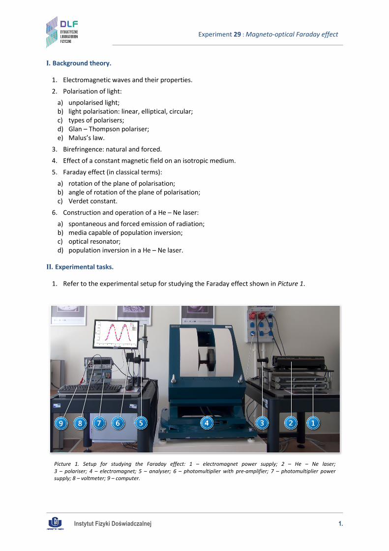
Experiment 29 : Magneto-optical Faraday effect
I. Background theory.
1. Electromagnetic waves and their properties. 2. Polarisation of light:
a) unpolarised light; b) light polarisation: linear, elliptical, circular; c) types of polarisers; d) Glan – Thompson polariser; e) Malus’s law.
3. Birefringence: natural and forced. 4. Effect of a constant magnetic field on an isotropic medium.
5. Faraday effect (in classical terms): a) rotation of the plane of polarisation; b) angle of rotation of the plane of polarisation; c) Verdet constant.
6. Construction and operation of a He – Ne laser: a) spontaneous and forced emission of radiation; b) media capable of population inversion; c) optical resonator; d) population inversion in a He – Ne laser.
II. Experimental tasks.
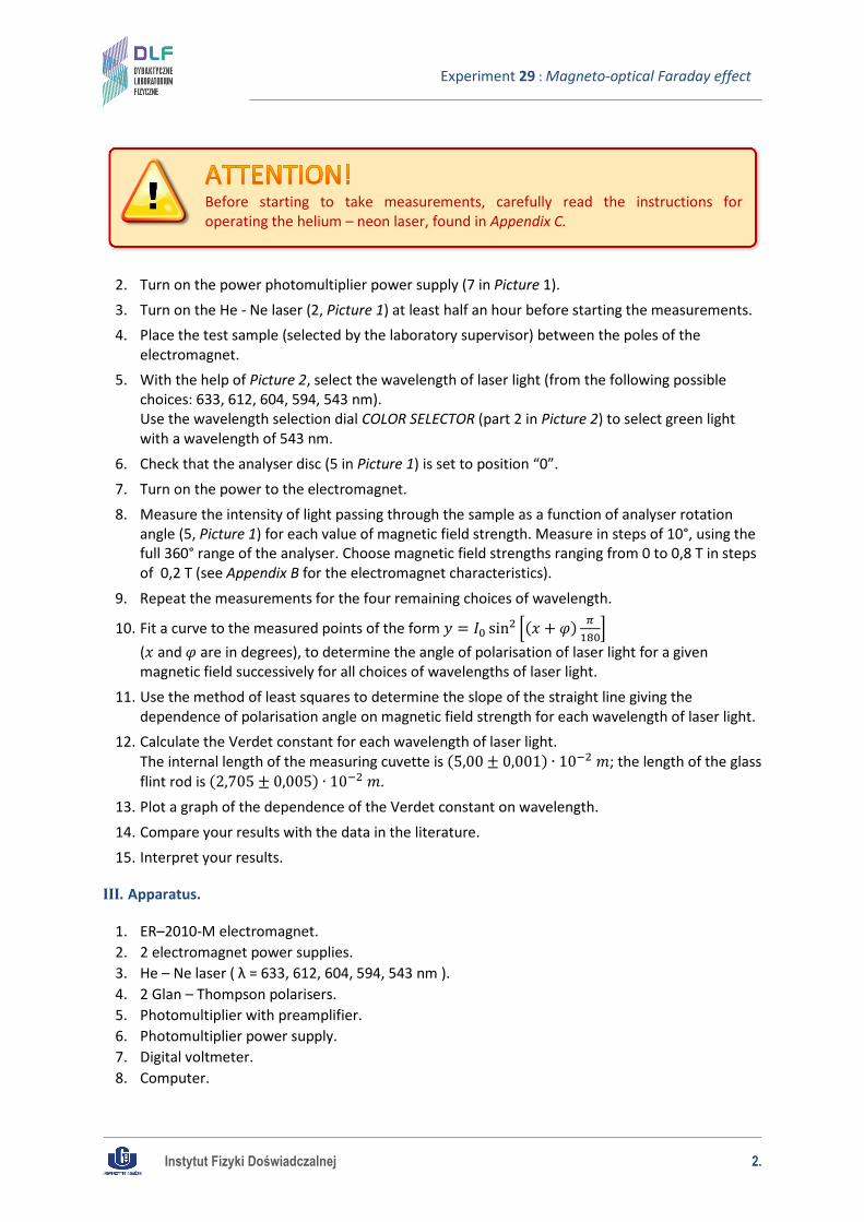
1. Refer to the experimental setup for studying the Faraday effect shown in Picture 1.
Picture 1. Setup for studying the Faraday effect: 1 – electromagnet power supply; 2 – He – Ne laser; 3 – polariser; 4 – electromagnet; 5 – analyser; 6 – photomultiplier with pre-amplifier; 7 – photomultiplier power supply; 8 – voltmeter; 9 – computer.
Instytut Fizyki Doświadczalnej 2.
Experiment 29 : Magneto-optical Faraday effect
2. Turn on the power photomultiplier power supply (7 in Picture 1). 3. Turn on the He - Ne laser (2, Picture 1) at least half an hour before starting the measurements. 4. Place the test sample (selected by the laboratory supervisor) between the poles of the
electromagnet. 5. With the help of Picture 2, select the wavelength of laser light (from the following possible
choices: 633, 612, 604, 594, 543 nm). Use the wavelength selection dial COLOR SELECTOR (part 2 in Picture 2) to select green light with a wavelength of 543 nm.
6. Check that the analyser disc (5 in Picture 1) is set to position “0”. 7. Turn on the power to the electromagnet. 8. Measure the intensity of light passing through the sample as a function of analyser rotation
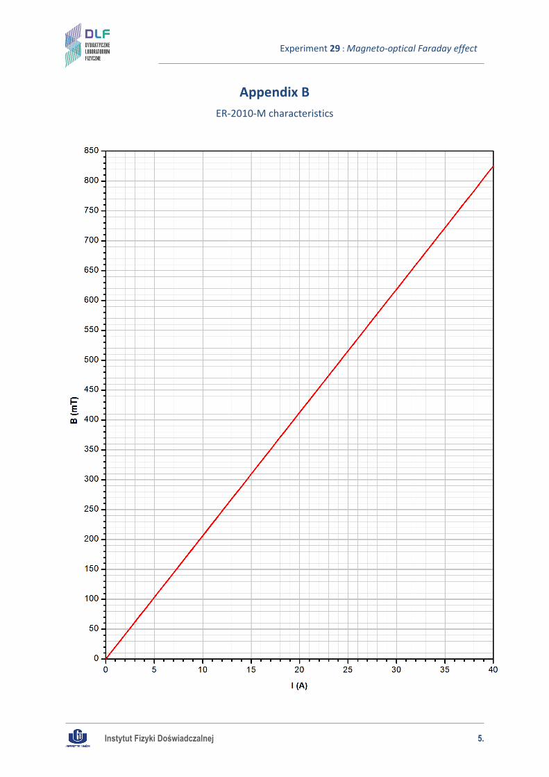
angle (5, Picture 1) for each value of magnetic field strength. Measure in steps of 10°, using the full 360° range of the analyser. Choose magnetic field strengths ranging from 0 to 0,8 T in steps of 0,2 T (see Appendix B for the electromagnet characteristics).
9. Repeat the measurements for the four remaining choices of wavelength.
10. Fit a curve to the measured points of the form 𝑦 = 𝐼0 sin2 �(𝑥 + 𝜑) 𝜋180
� (𝑥 and 𝜑 are in degrees), to determine the angle of polarisation of laser light for a given magnetic field successively for all choices of wavelengths of laser light.
11. Use the method of least squares to determine the slope of the straight line giving the dependence of polarisation angle on magnetic field strength for each wavelength of laser light.
12. Calculate the Verdet constant for each wavelength of laser light. The internal length of the measuring cuvette is (5,00 ± 0,001) ∙ 10−2 𝑚; the length of the glass flint rod is (2,705 ± 0,005) ∙ 10−2 𝑚.
13. Plot a graph of the dependence of the Verdet constant on wavelength. 14. Compare your results with the data in the literature. 15. Interpret your results.
III. Apparatus.
1. ER–2010-M electromagnet. 2. 2 electromagnet power supplies. 3. He – Ne laser ( λ = 633, 612, 604, 594, 543 nm ). 4. 2 Glan – Thompson polarisers. 5. Photomultiplier with preamplifier. 6. Photomultiplier power supply. 7. Digital voltmeter. 8. Computer.
Before starting to take measurements, carefully read the instructions for operating the helium – neon laser, found in Appendix C.
Instytut Fizyki Doświadczalnej 3.
Experiment 29 : Magneto-optical Faraday effect
IV. Literature.
1. M. Young – “Optics and Lasers”, Springer, 1977. 2. W.A. Shurcliff, S.S. Bellard – “Polarized Light”, Princeton 1964. 3. K. Shimoda – “Introduction to Laser Physics”, Springer, 1986. 4. J. Orear – “Physics”, Vol. 2., Macmillan Publishing Co., Inc., 1979. 5. O. Svelto – “Principles of Lasers”, Plenum, New York 1998. 6. H. Abramczyk – “Introduction to Laser Spectroscopy”, Elsevier, 2005.
Instytut Fizyki Doświadczalnej 4.
Experiment 29 : Magneto-optical Faraday effect
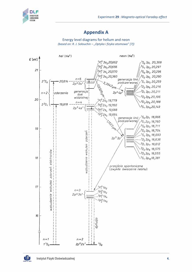
Appendix A Energy level diagrams for helium and neon
(based on: R. J. Sołouchin – „Optyka i fizyka atomowa” [7])
Instytut Fizyki Doświadczalnej 5.
Experiment 29 : Magneto-optical Faraday effect
Appendix B ER-2010-M characteristics
Instytut Fizyki Doświadczalnej 6.
Experiment 29 : Magneto-optical Faraday effect
Appendix C Helium – neon laser operating instructions
5 Line Tuneable He-Ne Laser System, Model 30603, REO Inc.
The helium – neon laser in this experiment is a tuneable laser and allows the generation of laser light with five possible wavelengths: 633, 612, 604, 594 and 543 nm. The laser should be turned on at least 30 minutes before starting measurements.
A. Turning on the laser.
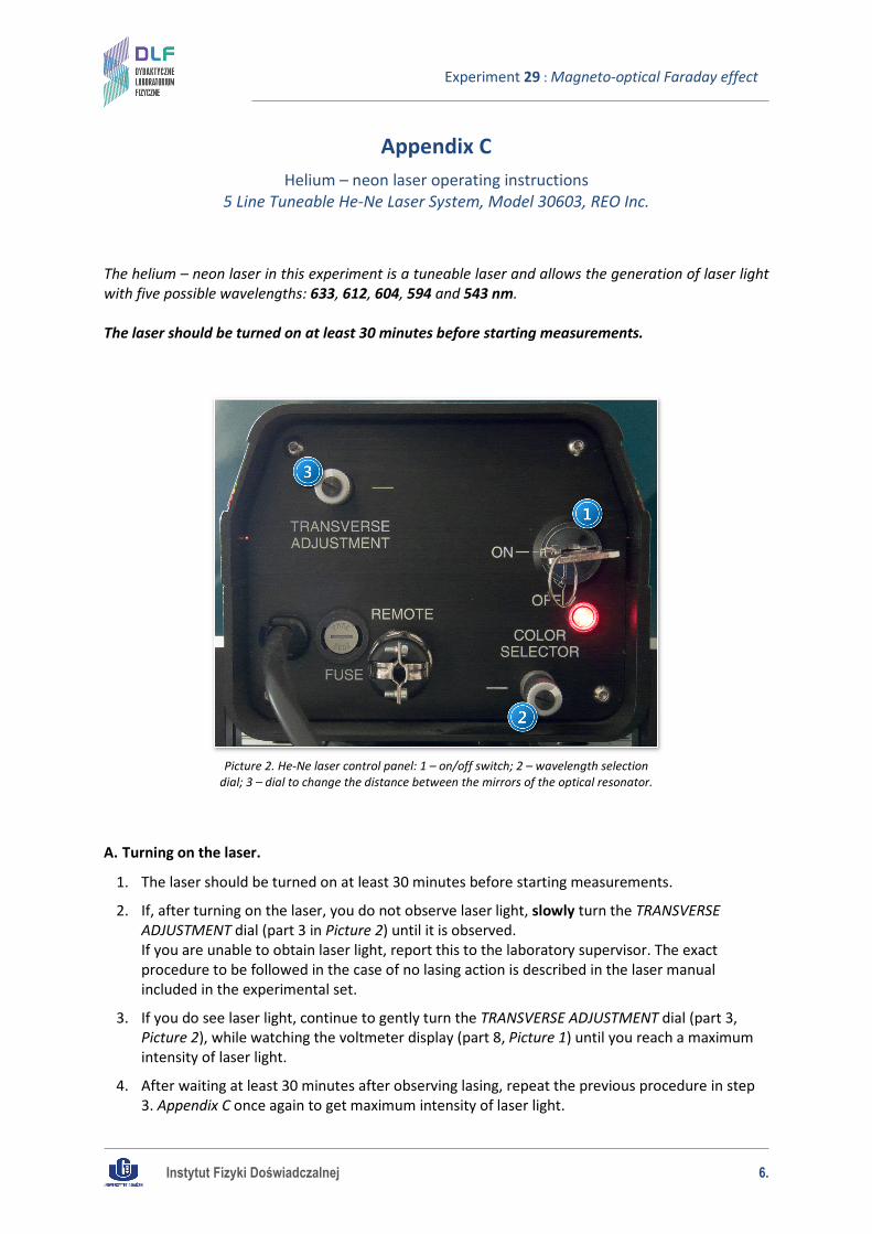
1. The laser should be turned on at least 30 minutes before starting measurements.
2. If, after turning on the laser, you do not observe laser light, slowly turn the TRANSVERSE ADJUSTMENT dial (part 3 in Picture 2) until it is observed. If you are unable to obtain laser light, report this to the laboratory supervisor. The exact procedure to be followed in the case of no lasing action is described in the laser manual included in the experimental set.
3. If you do see laser light, continue to gently turn the TRANSVERSE ADJUSTMENT dial (part 3, Picture 2), while watching the voltmeter display (part 8, Picture 1) until you reach a maximum intensity of laser light.
4. After waiting at least 30 minutes after observing lasing, repeat the previous procedure in step 3. Appendix C once again to get maximum intensity of laser light.
Picture 2. He-Ne laser control panel: 1 – on/off switch; 2 – wavelength selection dial; 3 – dial to change the distance between the mirrors of the optical resonator.
Instytut Fizyki Doświadczalnej 7.
Experiment 29 : Magneto-optical Faraday effect
B. Taking measurements with the laser.
1. Changing the wavelength of the emitted laser light is done using the COLOR SELECTOR dial (part 2, Picture 2). Do not change settings on the TRANSVERSE ADJUSTMENT knob (part 3, Picture 2) during measurements.
2. In order to change the wavelength of laser light, gently turn the knob COLOR SELECTOR until the laser emits light of the desired wavelength. Turning to the right decreases the wavelength and to the left increases the wavelength.
3. After roughly setting the wavelength of light, you should carefully find the setting which ensures maximum intensity. To do this, very slowly adjust the COLOR SELECTOR dial while observing the voltmeter (part 7, Picture 1) until you get maximum intensity.
4. After setting the desired wavelength, perform measurements according to steps II.5. – II.7. (of Experimental tasks).
C. Turning off the laser.
1. After measurements, use the “COLOR SELECTOR” dial to select the green line (λ = 543 nm).
2. Report to the laboratory supervisor that you have completed measurements using the laser.
Emission maxima for wavelengths 604 and 612 nm are poorly separated and very close to each other. In order to select one of these wavelengths you should very carefully monitor for changes in light intensity.
Instytut Fizyki Doświadczalnej 8.
Experiment 29 : Magneto-optical Faraday effect
Appendix D Operating the electromagnet power supply
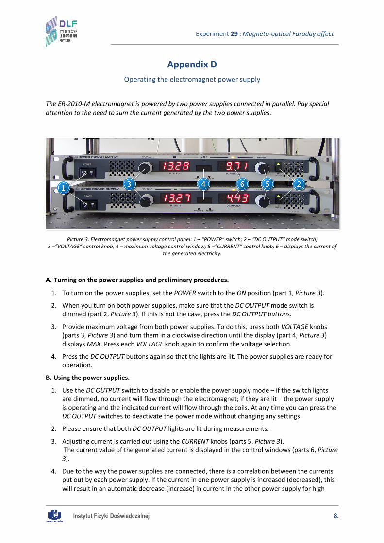
The ER-2010-M electromagnet is powered by two power supplies connected in parallel. Pay special attention to the need to sum the current generated by the two power supplies.
A. Turning on the power supplies and preliminary procedures.
1. To turn on the power supplies, set the POWER switch to the ON position (part 1, Picture 3).
2. When you turn on both power supplies, make sure that the DC OUTPUT mode switch is dimmed (part 2, Picture 3). If this is not the case, press the DC OUTPUT buttons.
3. Provide maximum voltage from both power supplies. To do this, press both VOLTAGE knobs (parts 3, Picture 3) and turn them in a clockwise direction until the display (part 4, Picture 3) displays MAX. Press each VOLTAGE knob again to confirm the voltage selection.
4. Press the DC OUTPUT buttons again so that the lights are lit. The power supplies are ready for operation.
B. Using the power supplies.
1. Use the DC OUTPUT switch to disable or enable the power supply mode – if the switch lights are dimmed, no current will flow through the electromagnet; if they are lit – the power supply is operating and the indicated current will flow through the coils. At any time you can press the DC OUTPUT switches to deactivate the power mode without changing any settings.
2. Please ensure that both DC OUTPUT lights are lit during measurements.
3. Adjusting current is carried out using the CURRENT knobs (parts 5, Picture 3). The current value of the generated current is displayed in the control windows (parts 6, Picture 3).
4. Due to the way the power supplies are connected, there is a correlation between the currents put out by each power supply. If the current in one power supply is increased (decreased), this will result in an automatic decrease (increase) in current in the other power supply for high
Picture 3. Electromagnet power supply control panel: 1 – “POWER” switch; 2 – “DC OUTPUT” mode switch; 3 –“VOLTAGE” control knob; 4 – maximum voltage control window; 5 –“CURRENT” control knob; 6 – displays the current of
the generated electricity.

Instytut Fizyki Doświadczalnej 9.
Experiment 29 : Magneto-optical Faraday effect
currents. The total current flowing in the coil is the sum of the currents displayed on the power supply control panels (parts 6, Picture 3).
C. Turning off the power supplies.
1. After the measurements, use the CURRENT knob to set the smallest possible current on both power supplies, turn off the output current using the DC OUTPUT switches and set both POWER switches to the OFF position.
2. Report to the laboratory supervisor that you have finished using the power supplies.
![TECHNICAL TRANSACTIONS CZASOPISMO TECHNICZNE · [6] and checking the possibility of corrosion using the Pourbaix diagram [17]. Siwowski described an example of corrosion of aluminium](https://static.fdocuments.pl/doc/165x107/5e848d11142e2475250eb11d/technical-transactions-czasopismo-techniczne-6-and-checking-the-possibility-of.jpg)

![arXiv:1607.05925v1 [astro-ph.SR] 20 Jul 2016 · arXiv:1607.05925v1 [astro-ph.SR] 20 Jul 2016 Astronomy & Astrophysicsmanuscript no. paper c ESO 2018 August 29, 2018 Multi-wavelength](https://static.fdocuments.pl/doc/165x107/5fa6a99d0ea9126fb349b915/arxiv160705925v1-astro-phsr-20-jul-2016-arxiv160705925v1-astro-phsr-20.jpg)