Finite element analysis of artificial disc with an ... · PDF fileFinite element analysis of...
8
Acta of Bioengineering and Biomechanics Original paper Vol. 14, No. 1, 2012 Finite element analysis of artificial disc with an elastomeric core in the lumbar spine P. BORKOWSKI 1 *, P. MAREK 1 , G. KRZESIŃSKI 1 , J. RYSZKOWSKA 2 , B. WAŚNIEWSKI 2 , P. WYMYSŁOWSKI 1 , T. ZAGRAJEK 1 1 The Faculty of Power Engineering and Applied Mechanics, Warsaw University of Technology, Warsaw, Poland. 2 The Faculty of Material Engineering, Warsaw University of Technology, Warsaw, Poland. This paper presents the application of finite element method in an artificial disc modelling. The prosthesis consisted of two metal plates and a flexible elastomeric core made of the nanocomposite polyurethane. Two types of connections between the plates and the core were compared: the device with an integral inlay and the device with a separate inlay coming into contact with the plates. The artifi- cial disc with a separate inlay imitated better the human intervertebral disc. The main target of this paper was to evaluate the characteris- tics of force–displacement and moment–angle for the new design of the prosthesis with a separate inlay under compression, sagittal bending, shear and axial rotation. For some analyzed cases except the axial rotation and shear, where the prosthesis was too flexible, the results were roughly similar to those observed in the human spinal segment. The material effort in the prosthesis under compressive load was comparable in both types of connections between the plates and the core. Key words: FE analysis, artificial disc, elastomeric core, lumbar spine 1. Introduction Nowadays many people suffer from spinal disor- ders which may be a cause of the low back pain syn- drome. One of the treatment methods is replacing the degenerative patient’s disc with an artificial device such as a prosthesis which relieves the pain and re- stores physiological motion of the operated spinal segment, consisting of two vertebras and an inter- vertebral disc [1]. The prosthesis should work safely for about fifty years and should not cause allergic response of the human body. The components of the prosthesis have to satisfy many criteria. One of them is to ensure low stress and strain levels within the ranges of loads and motions that occur in the spine. Stress and strain evaluation in the spinal segment with the artificial disc is a complex problem and thus involves numerical simulation. This paper presents the application of the finite element method in an artificial disc modelling. Two types of artificial discs can be identified: the ball-joint and flexible prostheses. The first type con- sists of two rigid metal plates with a convex inlay [2] or two rigid metal components (convexo-concave) [3]. Currently, the ball-joint devices are most commonly implanted. Recently, some results were published indicating that inaccurate imitation of kinematics and insufficient resistance to the shearing forces in the spinal segments with the ball-joint prostheses were the causes of injuries to the facet joints [4]. As quite distinct from this design, the flexible device has an elastomeric part imitating the human disc. The main problem is how to fix the inlay to the vertebrae, so few devices were implanted. They additionally had two porous metal plates adjacent to ______________________________ * Corresponding author: Paweł Borkowski, The Faculty of Power Engineering and Applied Mechanics, Warsaw University of Tech- nology, ul. Nowowiejska 24, 00-665 Warsaw, Poland. Tel./fax: +48 22 234 50 72, e-mail: [email protected] Received: September 23rd, 2010 Accepted for publication: January 18th, 2012
-
Upload
truongthuy -
Category
Documents
-
view
222 -
download
3
Transcript of Finite element analysis of artificial disc with an ... · PDF fileFinite element analysis of...
Acta of Bioengineering and Biomechanics Original paperVol. 14, No. 1, 2012
Finite element analysis of artificial discwith an elastomeric core in the lumbar spine
P. BORKOWSKI1*, P. MAREK1, G. KRZESIŃSKI1, J. RYSZKOWSKA2,B. WAŚNIEWSKI2, P. WYMYSŁOWSKI1, T. ZAGRAJEK1
1 The Faculty of Power Engineering and Applied Mechanics, Warsaw University of Technology, Warsaw, Poland.2 The Faculty of Material Engineering, Warsaw University of Technology, Warsaw, Poland.
This paper presents the application of finite element method in an artificial disc modelling. The prosthesis consisted of two metalplates and a flexible elastomeric core made of the nanocomposite polyurethane. Two types of connections between the plates and thecore were compared: the device with an integral inlay and the device with a separate inlay coming into contact with the plates. The artifi-cial disc with a separate inlay imitated better the human intervertebral disc. The main target of this paper was to evaluate the characteris-tics of force–displacement and moment–angle for the new design of the prosthesis with a separate inlay under compression, sagittalbending, shear and axial rotation. For some analyzed cases except the axial rotation and shear, where the prosthesis was too flexible, theresults were roughly similar to those observed in the human spinal segment. The material effort in the prosthesis under compressive loadwas comparable in both types of connections between the plates and the core.
Key words: FE analysis, artificial disc, elastomeric core, lumbar spine
1. Introduction
Nowadays many people suffer from spinal disor-ders which may be a cause of the low back pain syn-drome. One of the treatment methods is replacing thedegenerative patient’s disc with an artificial devicesuch as a prosthesis which relieves the pain and re-stores physiological motion of the operated spinalsegment, consisting of two vertebras and an inter-vertebral disc [1]. The prosthesis should work safelyfor about fifty years and should not cause allergicresponse of the human body. The components of theprosthesis have to satisfy many criteria. One of themis to ensure low stress and strain levels within theranges of loads and motions that occur in the spine.Stress and strain evaluation in the spinal segmentwith the artificial disc is a complex problem and thus
involves numerical simulation. This paper presentsthe application of the finite element method in anartificial disc modelling.
Two types of artificial discs can be identified: theball-joint and flexible prostheses. The first type con-sists of two rigid metal plates with a convex inlay [2]or two rigid metal components (convexo-concave) [3].Currently, the ball-joint devices are most commonlyimplanted. Recently, some results were publishedindicating that inaccurate imitation of kinematics andinsufficient resistance to the shearing forces in thespinal segments with the ball-joint prostheses were thecauses of injuries to the facet joints [4].
As quite distinct from this design, the flexibledevice has an elastomeric part imitating the humandisc. The main problem is how to fix the inlay tothe vertebrae, so few devices were implanted. Theyadditionally had two porous metal plates adjacent to
______________________________
* Corresponding author: Paweł Borkowski, The Faculty of Power Engineering and Applied Mechanics, Warsaw University of Tech-nology, ul. Nowowiejska 24, 00-665 Warsaw, Poland. Tel./fax: +48 22 234 50 72, e-mail: [email protected]
Received: September 23rd, 2010Accepted for publication: January 18th, 2012
P. BORKOWSKI et al.60
the inlay which enabled the prosthesis to grow intothe vertebral body [4], [5]. The second question ishow to avoid the fatigue of the inlay which causesfracture propagation inside the elastomeric inlay orat the interface between the inlay and plates [5].This is particularly important if the interface is in-separable. Therefore, the shape of an outer region ofthe elastomeric inlay should be specially designedto prevent relatively high strains occurring duringtranslational and rotational movements. The mate-rial properties of the inlay should be fitted to theload magnitudes and the ranges of motion occurringin the spine. Additionally the joint between theinlay and the plates should be resistant to wear.These requirements could be met due to a choice ofa composite material whose properties could beadjusted and even changed across the inlay. Forinstance, nanocomposite polyurethane exhibits fea-tures like biocompatibility, strength and fatigueresistance, depending on its chemical composition,and reveals good cohesion at the interface betweenmetallic alloys. The new manufacturing technologyof this material was recently developed at WUT [6].Hence, the nanocomposite polyurethane is consid-ered as the material which could be applied in anelastomeric inlay [4].
Another design of the flexible artificial disc is theprosthesis with a frictional joint, where the separateelastomeric inlay could slip between the plates. Themain drawback of this device is obviously wear de-bris, but the use of a more rigid and resistant materialof the inlay could result in similar flexibility as thatachieved for the prosthesis with an integral inlay.This type of joint could also be characterized by theconsiderably lower strain and stress values in com-parison with those of an integral inlay, especiallyduring rotational movements. Besides, the commonproblem with the ball-joint and flexible devices layin a fusion of the implanted spinal segment, causedprobably by the implant design and (or) the methodof implantation (to what extent the degenerative discwas removed). This fusion was created by tissueingrowth between the implant plates. Hence, for ex-ample, it seems that short-term successful results ofimplantation of the modern flexible prosthesisPhysio-L [4] should be verified in a longer time pe-riod because of the possibility of spinal segmentfusion. In the case of the prosthesis with a separateinlay, the outer regions of the elastomeric inlay neednot to be removed because of high strain, so it seemsto be less susceptible to unwanted fusion. Thus, thistype of the elastomeric prosthesis was mainly takeninto account in this paper.
2. Methods
2.1. Finite element model
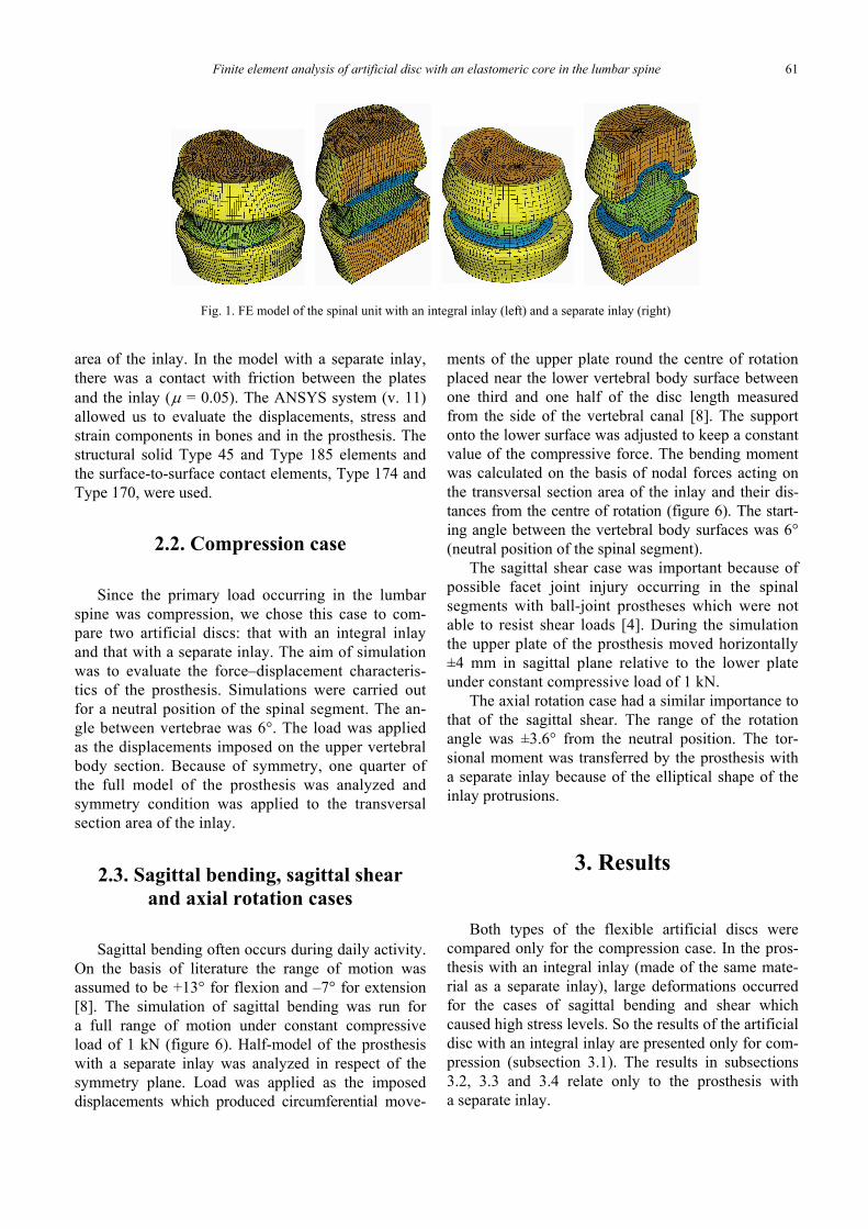
The finite element model of the functional spinalsegment included the fragments of lumbar vertebralbodies similar to L4 and L5 and the prosthesis. Bothtypes of the flexible artificial disc were analyzed (fig-ure 1). The prostheses consisted of two metal platesand the elastomeric inlay. The size of intervertebralspace was the same for the prosthesis with an integralinlay and that with a separate inlay. The isotropiclinear model of material was assumed for the corticalbone, trabecular bone and the metal plate made of Co–Cr–Mo alloy (the table) [7]. A nonlinear hiperelasticincompressible Gent material was used for the inlaymodel made of polyurethane nanocomposite (1):
⎥⎥⎦
⎤
⎢⎢⎣
⎡−−+
⎭⎬⎫
⎩⎨⎧ −−=
−
)ln21(1)3(1ln21 2
11
0 JJdJ
IJGWm
m ,
(1)where:
W – the strain energy,G0 = 5 MPa – the initial shear modulus,Jm = 80 – the limiting value of (I1–3); I1 = J–2/3·( 2
1λ
+ 22λ + 2
3λ ),J – the volume ratio,λi – the principal extension ratios,d = 0 – the incompressibility parameter, d = 2/K
(K – the bulk modulus).
Table. Isotropic material properties
Part Young’s modulusE (MPa)
Poisson’sratio ν
Cortical bone 12 000 0.35Trabecular bone 400 0.40Co–Cr–Mo plate 200 000 0.30
In both cases shown in figure 1, metal plates werebound to the vertebrae. The model analysed wassymmetrical in respect of the horizontal and verticalplanes. A load was applied as the displacements im-posed on the upper vertebral body section. Except thecompression case, the displacements were appliedalso to the lower vertebral body section in order tokeep a constant value of the compressive force. Theranges of motion for load cases were taken from theliterature [8]. Forces and moments were calculatedbased on the nodal forces at the transversal section
Finite element analysis of artificial disc with an elastomeric core in the lumbar spine 61
area of the inlay. In the model with a separate inlay,there was a contact with friction between the platesand the inlay (μ = 0.05). The ANSYS system (v. 11)allowed us to evaluate the displacements, stress andstrain components in bones and in the prosthesis. Thestructural solid Type 45 and Type 185 elements andthe surface-to-surface contact elements, Type 174 andType 170, were used.
2.2. Compression case
Since the primary load occurring in the lumbarspine was compression, we chose this case to com-pare two artificial discs: that with an integral inlayand that with a separate inlay. The aim of simulationwas to evaluate the force–displacement characteris-tics of the prosthesis. Simulations were carried outfor a neutral position of the spinal segment. The an-gle between vertebrae was 6°. The load was appliedas the displacements imposed on the upper vertebralbody section. Because of symmetry, one quarter ofthe full model of the prosthesis was analyzed andsymmetry condition was applied to the transversalsection area of the inlay.
2.3. Sagittal bending, sagittal shearand axial rotation cases
Sagittal bending often occurs during daily activity.On the basis of literature the range of motion wasassumed to be +13° for flexion and –7° for extension[8]. The simulation of sagittal bending was run fora full range of motion under constant compressiveload of 1 kN (figure 6). Half-model of the prosthesiswith a separate inlay was analyzed in respect of thesymmetry plane. Load was applied as the imposeddisplacements which produced circumferential move-
ments of the upper plate round the centre of rotationplaced near the lower vertebral body surface betweenone third and one half of the disc length measuredfrom the side of the vertebral canal [8]. The supportonto the lower surface was adjusted to keep a constantvalue of the compressive force. The bending momentwas calculated on the basis of nodal forces acting onthe transversal section area of the inlay and their dis-tances from the centre of rotation (figure 6). The start-ing angle between the vertebral body surfaces was 6°(neutral position of the spinal segment).
The sagittal shear case was important because ofpossible facet joint injury occurring in the spinalsegments with ball-joint prostheses which were notable to resist shear loads [4]. During the simulationthe upper plate of the prosthesis moved horizontally±4 mm in sagittal plane relative to the lower plateunder constant compressive load of 1 kN.
The axial rotation case had a similar importance tothat of the sagittal shear. The range of the rotationangle was ±3.6° from the neutral position. The tor-sional moment was transferred by the prosthesis witha separate inlay because of the elliptical shape of theinlay protrusions.
3. Results
Both types of the flexible artificial discs werecompared only for the compression case. In the pros-thesis with an integral inlay (made of the same mate-rial as a separate inlay), large deformations occurredfor the cases of sagittal bending and shear whichcaused high stress levels. So the results of the artificialdisc with an integral inlay are presented only for com-pression (subsection 3.1). The results in subsections3.2, 3.3 and 3.4 relate only to the prosthesis witha separate inlay.
Fig. 1. FE model of the spinal unit with an integral inlay (left) and a separate inlay (right)
P. BORKOWSKI et al.62
3.1. Comparison of two typesof prostheses under compression
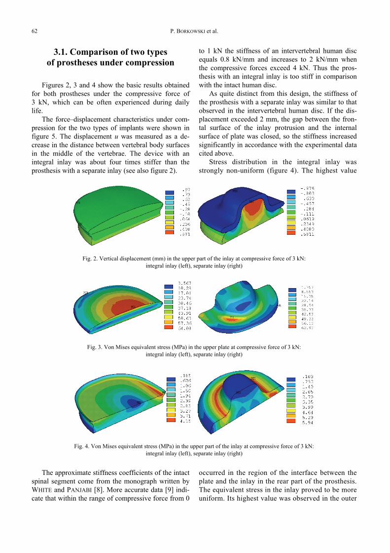
Figures 2, 3 and 4 show the basic results obtainedfor both prostheses under the compressive force of3 kN, which can be often experienced during dailylife.
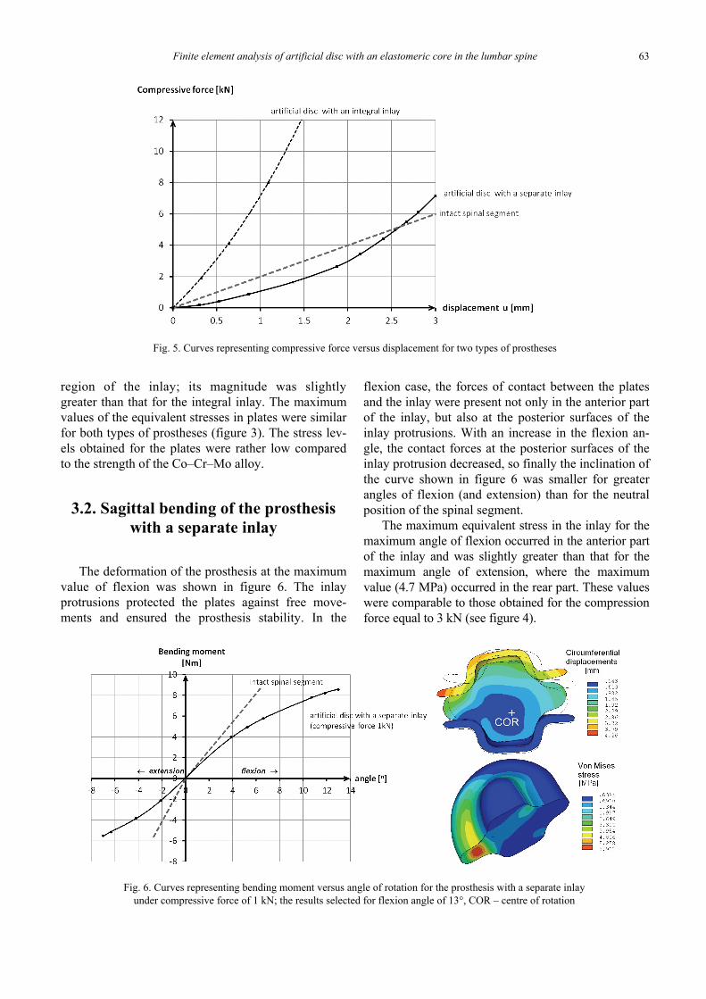
The force–displacement characteristics under com-pression for the two types of implants were shown infigure 5. The displacement u was measured as a de-crease in the distance between vertebral body surfacesin the middle of the vertebrae. The device with anintegral inlay was about four times stiffer than theprosthesis with a separate inlay (see also figure 2).
The approximate stiffness coefficients of the intactspinal segment come from the monograph written byWHITE and PANJABI [8]. More accurate data [9] indi-cate that within the range of compressive force from 0
to 1 kN the stiffness of an intervertebral human discequals 0.8 kN/mm and increases to 2 kN/mm whenthe compressive forces exceed 4 kN. Thus the pros-thesis with an integral inlay is too stiff in comparisonwith the intact human disc.
As quite distinct from this design, the stiffness ofthe prosthesis with a separate inlay was similar to thatobserved in the intervertebral human disc. If the dis-placement exceeded 2 mm, the gap between the fron-tal surface of the inlay protrusion and the internalsurface of plate was closed, so the stiffness increasedsignificantly in accordance with the experimental datacited above.
Stress distribution in the integral inlay wasstrongly non-uniform (figure 4). The highest value
occurred in the region of the interface between theplate and the inlay in the rear part of the prosthesis.The equivalent stress in the inlay proved to be moreuniform. Its highest value was observed in the outer
Fig. 2. Vertical displacement (mm) in the upper part of the inlay at compressive force of 3 kN:integral inlay (left), separate inlay (right)
Fig. 3. Von Mises equivalent stress (MPa) in the upper plate at compressive force of 3 kN:integral inlay (left), separate inlay (right)
Fig. 4. Von Mises equivalent stress (MPa) in the upper part of the inlay at compressive force of 3 kN:integral inlay (left), separate inlay (right)
Finite element analysis of artificial disc with an elastomeric core in the lumbar spine 63
region of the inlay; its magnitude was slightlygreater than that for the integral inlay. The maximumvalues of the equivalent stresses in plates were similarfor both types of prostheses (figure 3). The stress lev-els obtained for the plates were rather low comparedto the strength of the Co–Cr–Mo alloy.
3.2. Sagittal bending of the prosthesiswith a separate inlay
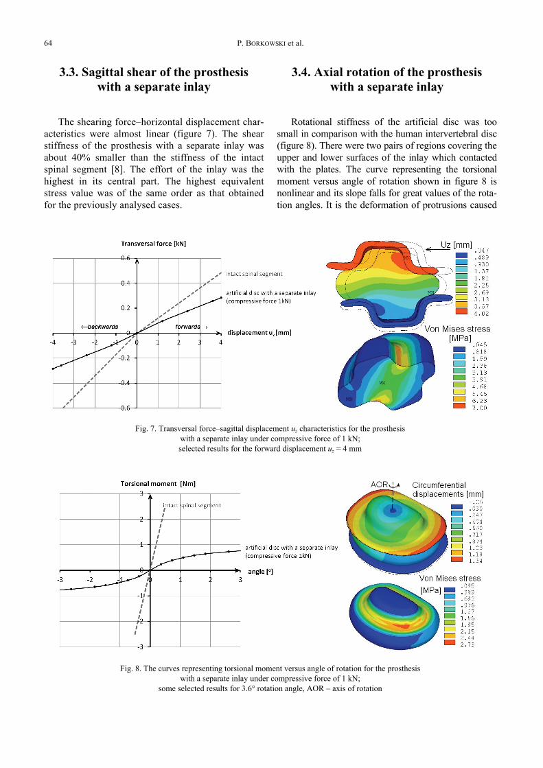
The deformation of the prosthesis at the maximumvalue of flexion was shown in figure 6. The inlayprotrusions protected the plates against free move-ments and ensured the prosthesis stability. In the
flexion case, the forces of contact between the platesand the inlay were present not only in the anterior partof the inlay, but also at the posterior surfaces of theinlay protrusions. With an increase in the flexion an-gle, the contact forces at the posterior surfaces of theinlay protrusion decreased, so finally the inclination ofthe curve shown in figure 6 was smaller for greaterangles of flexion (and extension) than for the neutralposition of the spinal segment.
The maximum equivalent stress in the inlay for themaximum angle of flexion occurred in the anterior partof the inlay and was slightly greater than that for themaximum angle of extension, where the maximumvalue (4.7 MPa) occurred in the rear part. These valueswere comparable to those obtained for the compressionforce equal to 3 kN (see figure 4).
Fig. 5. Curves representing compressive force versus displacement for two types of prostheses
Fig. 6. Curves representing bending moment versus angle of rotation for the prosthesis with a separate inlayunder compressive force of 1 kN; the results selected for flexion angle of 13°, COR – centre of rotation
P. BORKOWSKI et al.64
3.3. Sagittal shear of the prosthesiswith a separate inlay
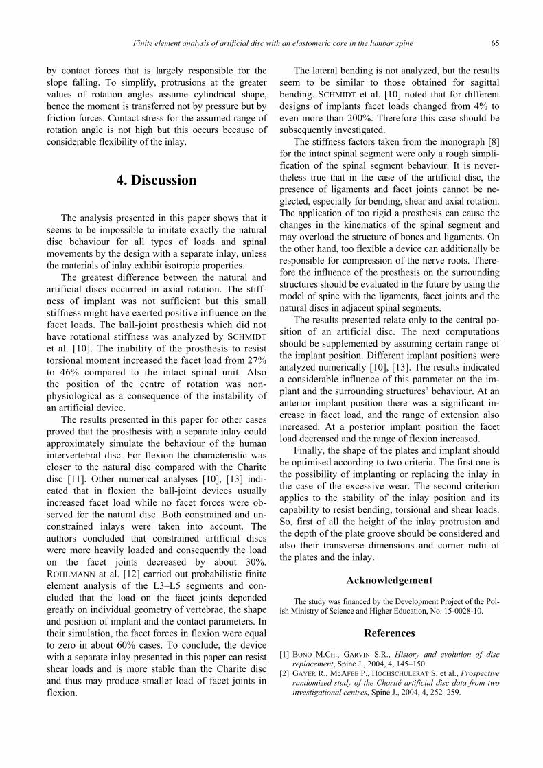
The shearing force–horizontal displacement char-acteristics were almost linear (figure 7). The shearstiffness of the prosthesis with a separate inlay wasabout 40% smaller than the stiffness of the intactspinal segment [8]. The effort of the inlay was thehighest in its central part. The highest equivalentstress value was of the same order as that obtainedfor the previously analysed cases.
3.4. Axial rotation of the prosthesiswith a separate inlay
Rotational stiffness of the artificial disc was toosmall in comparison with the human intervertebral disc(figure 8). There were two pairs of regions covering theupper and lower surfaces of the inlay which contactedwith the plates. The curve representing the torsionalmoment versus angle of rotation shown in figure 8 isnonlinear and its slope falls for great values of the rota-tion angles. It is the deformation of protrusions caused
Fig. 7. Transversal force–sagittal displacement uz characteristics for the prosthesiswith a separate inlay under compressive force of 1 kN;selected results for the forward displacement uz = 4 mm
Fig. 8. The curves representing torsional moment versus angle of rotation for the prosthesiswith a separate inlay under compressive force of 1 kN;
some selected results for 3.6° rotation angle, AOR – axis of rotation
Finite element analysis of artificial disc with an elastomeric core in the lumbar spine 65
by contact forces that is largely responsible for theslope falling. To simplify, protrusions at the greatervalues of rotation angles assume cylindrical shape,hence the moment is transferred not by pressure but byfriction forces. Contact stress for the assumed range ofrotation angle is not high but this occurs because ofconsiderable flexibility of the inlay.
4. Discussion
The analysis presented in this paper shows that itseems to be impossible to imitate exactly the naturaldisc behaviour for all types of loads and spinalmovements by the design with a separate inlay, unlessthe materials of inlay exhibit isotropic properties.
The greatest difference between the natural andartificial discs occurred in axial rotation. The stiff-ness of implant was not sufficient but this smallstiffness might have exerted positive influence on thefacet loads. The ball-joint prosthesis which did nothave rotational stiffness was analyzed by SCHMIDTet al. [10]. The inability of the prosthesis to resisttorsional moment increased the facet load from 27%to 46% compared to the intact spinal unit. Alsothe position of the centre of rotation was non-physiological as a consequence of the instability ofan artificial device.
The results presented in this paper for other casesproved that the prosthesis with a separate inlay couldapproximately simulate the behaviour of the humanintervertebral disc. For flexion the characteristic wascloser to the natural disc compared with the Charitedisc [11]. Other numerical analyses [10], [13] indi-cated that in flexion the ball-joint devices usuallyincreased facet load while no facet forces were ob-served for the natural disc. Both constrained and un-constrained inlays were taken into account. Theauthors concluded that constrained artificial discswere more heavily loaded and consequently the loadon the facet joints decreased by about 30%.ROHLMANN at al. [12] carried out probabilistic finiteelement analysis of the L3–L5 segments and con-cluded that the load on the facet joints dependedgreatly on individual geometry of vertebrae, the shapeand position of implant and the contact parameters. Intheir simulation, the facet forces in flexion were equalto zero in about 60% cases. To conclude, the devicewith a separate inlay presented in this paper can resistshear loads and is more stable than the Charite discand thus may produce smaller load of facet joints inflexion.
The lateral bending is not analyzed, but the resultsseem to be similar to those obtained for sagittalbending. SCHMIDT et al. [10] noted that for differentdesigns of implants facet loads changed from 4% toeven more than 200%. Therefore this case should besubsequently investigated.
The stiffness factors taken from the monograph [8]for the intact spinal segment were only a rough simpli-fication of the spinal segment behaviour. It is never-theless true that in the case of the artificial disc, thepresence of ligaments and facet joints cannot be ne-glected, especially for bending, shear and axial rotation.The application of too rigid a prosthesis can cause thechanges in the kinematics of the spinal segment andmay overload the structure of bones and ligaments. Onthe other hand, too flexible a device can additionally beresponsible for compression of the nerve roots. There-fore the influence of the prosthesis on the surroundingstructures should be evaluated in the future by using themodel of spine with the ligaments, facet joints and thenatural discs in adjacent spinal segments.
The results presented relate only to the central po-sition of an artificial disc. The next computationsshould be supplemented by assuming certain range ofthe implant position. Different implant positions wereanalyzed numerically [10], [13]. The results indicateda considerable influence of this parameter on the im-plant and the surrounding structures’ behaviour. At ananterior implant position there was a significant in-crease in facet load, and the range of extension alsoincreased. At a posterior implant position the facetload decreased and the range of flexion increased.
Finally, the shape of the plates and implant shouldbe optimised according to two criteria. The first one isthe possibility of implanting or replacing the inlay inthe case of the excessive wear. The second criterionapplies to the stability of the inlay position and itscapability to resist bending, torsional and shear loads.So, first of all the height of the inlay protrusion andthe depth of the plate groove should be considered andalso their transverse dimensions and corner radii ofthe plates and the inlay.
Acknowledgement
The study was financed by the Development Project of the Pol-ish Ministry of Science and Higher Education, No. 15-0028-10.
References
[1] BONO M.CH., GARVIN S.R., History and evolution of discreplacement, Spine J., 2004, 4, 145–150.
[2] GAYER R., McAFEE P., HOCHSCHULERAT S. et al., Prospectiverandomized study of the Charité artificial disc data from twoinvestigational centres, Spine J., 2004, 4, 252–259.
P. BORKOWSKI et al.66
[3] MATHEWS H.H., LEHUEC J.CH., FRIESEM T. et al., Designrationale and biomechanics of Maverick Total Disc ar-throplasty with early clinical results, Spine J., 2004, 4,268–275.
[4] PIMENTA L., SPRINGMULLER R., LEE C.K., Clinical perform-ance of an elastomeric lumbar disc replacement: Minimum 12months follow up, SAS Journal, 2010, 4, 1, 16–25.
[5] CUNNINGHAM B.W., LOWERY G. L., SERHAN H.A., Total discreplacement arthroplasty using the AcroFlex lumbar disc:a non-human primate model, Eur. Spine J., 2002, 11, S115–3.
[6] ZAWADZAK E., BIL M., RYSZKOWSKA J. et al., Polyurethanefoams electrophoretically coated with carbon nanotubes fortissue engineering scaffolds, Biomed. Mater., 2008, 4, 158–164.
[7] KĘDZIOR K., BORKOWSKI P., KRZESIŃSKI G., SKALSKI K.,ZAGRAJEK T., A nonlinear analysis of the human vertebralcolumn and medical recommendations that follow, Bulletin ofthe Polish Academy of Sciences, Technical Sciences, 2005,53, 3, 179–194.
[8] WHITE A.A., PANJABI M.M. (eds.), Clinical Biomechanic ofthe Spine, ed. 2. Lippincot-Williams & Wilkins, 1990.
[9] EIJKELKAMP M.F., van DONKELAAR C.C., VELDHUIZEN A.G.et al., Requirements for an artificial intervertebral disc, The In-ternational Journal of Artificial Organs, 2001, 24, 311–321.
[10] SCHMIDT H., MIDDERHOFF S., ADKINS K., WILKE H.J., Theeffect of different design concepts in lumbar total disc ar-throplasty on the range of motion, facet joint forces and in-stantaneous center of rotation of a L4-5 segment, EuropeanSpine Journal, 2009, 18, 11, 1695–1705.
[11] SCHMIDT H., GALBUSERA F., ROHLMANN A. et al., Effect ofmultilevel lumbar disc arthroplasty on spine kinematics andfacet joint loads in flexion and extension: a finite elementanalysis, European Spine Journal, Online First™, 2 April,2010.
[12] ROHLMANN A., MANN A., ZANDER T., BERGMANN G., Effectof an artificial disc on lumbar spine biomechanics: a prob-abilistic finite element study, European Spine Journal, 2009,18, 1, 89–97.
[13] DOORIS A.P., GOEL V.K., GROSLAND N.M. et al., Load-sharing between anterior and posterior elements in a lumbarmotion segment implanted with an artificial disc, Spine,2001, 26–6, E122-E129.