Dr. Mietek Glinkowski, P.E. Vacuum Switching ABB Inc. …
44
© ABB PTPM - 1 - 4-Aug-08 Vacuum Switching TUTORIAL Dr. Mietek Glinkowski, P.E. ABB Inc.
Transcript of Dr. Mietek Glinkowski, P.E. Vacuum Switching ABB Inc. …
©AB
B PT
PM-1
-4-
Aug-
08
Vacuum SwitchingTUTORIAL
Dr. Mietek Glinkowski, P.E.ABB Inc.
©AB
B PT
PM-2
-4-
Aug-
08
Presented at the IEEE Tutorial – Design & Application of Power Circuit Breakers, July 2008Material may be copyrighted.
Vacuum interrupters.Their Design, Mechanical and
Electrical Characteristics
©AB
B PT
PM-3
-4-
Aug-
08
Presented at the IEEE Tutorial – Design & Application of Power Circuit Breakers, July 2008Material may be copyrighted.
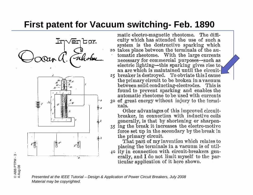
First patent for Vacuum switching- Feb. 1890
©AB
B PT
PM-4
-4-
Aug-
08
Presented at the IEEE Tutorial – Design & Application of Power Circuit Breakers, July 2008Material may be copyrighted.
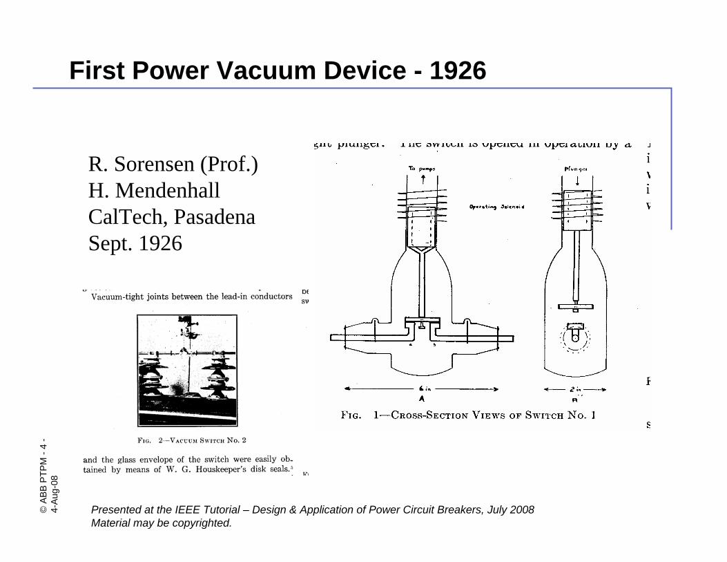
First Power Vacuum Device - 1926
R. Sorensen (Prof.)H. MendenhallCalTech, PasadenaSept. 1926
©AB
B PT
PM-5
-4-
Aug-
08
Presented at the IEEE Tutorial – Design & Application of Power Circuit Breakers, July 2008Material may be copyrighted.
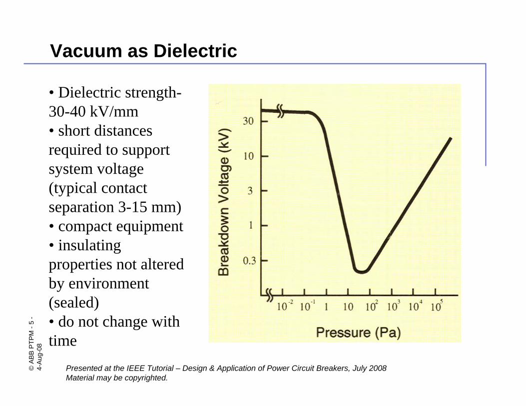
Vacuum as Dielectric
• Dielectric strength-30-40 kV/mm• short distances required to support system voltage (typical contact separation 3-15 mm)• compact equipment• insulating properties not altered by environment (sealed) • do not change with time
©AB
B PT
PM-6
-4-
Aug-
08
Presented at the IEEE Tutorial – Design & Application of Power Circuit Breakers, July 2008Material may be copyrighted.
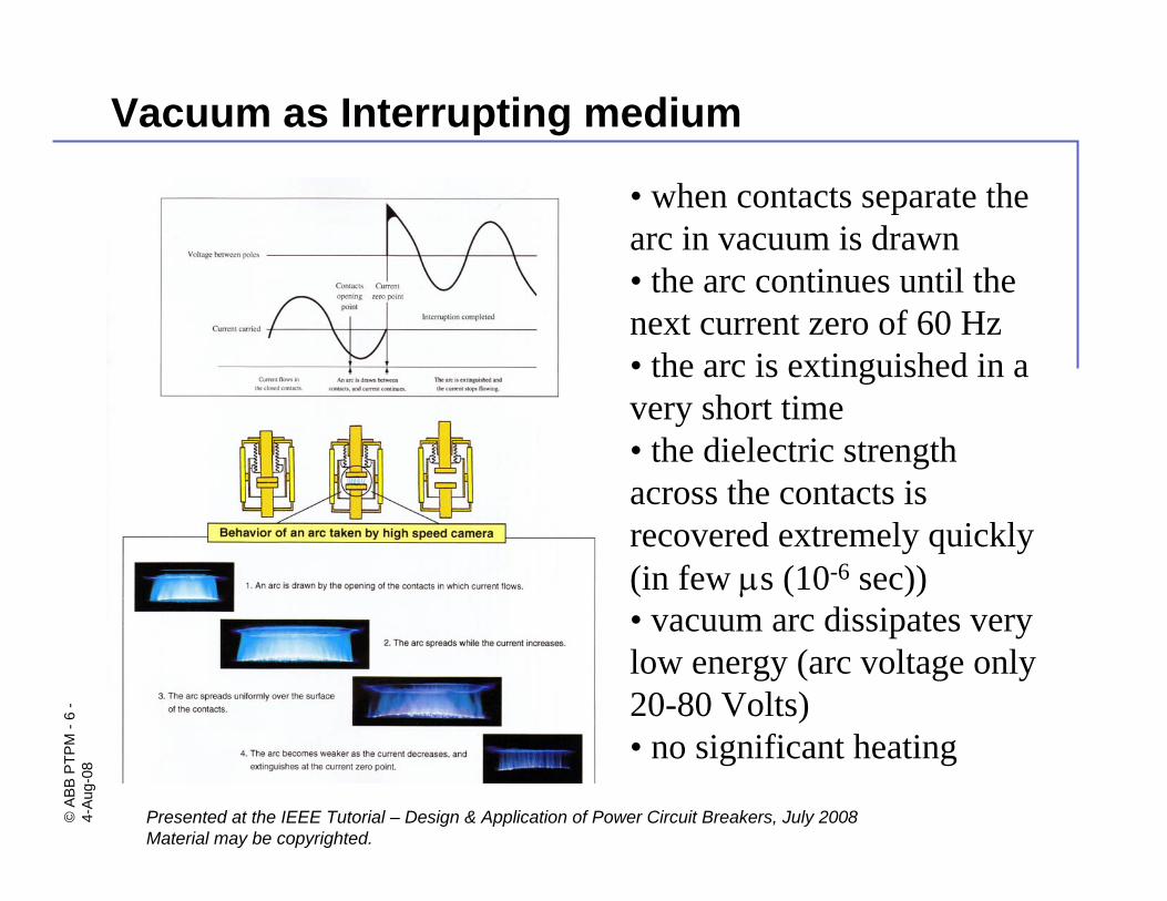
Vacuum as Interrupting medium
• when contacts separate the arc in vacuum is drawn• the arc continues until the next current zero of 60 Hz• the arc is extinguished in a very short time• the dielectric strength across the contacts is recovered extremely quickly (in few μs (10-6 sec))• vacuum arc dissipates very low energy (arc voltage only 20-80 Volts)• no significant heating
©AB
B PT
PM-7
-4-
Aug-
08
Presented at the IEEE Tutorial – Design & Application of Power Circuit Breakers, July 2008Material may be copyrighted.
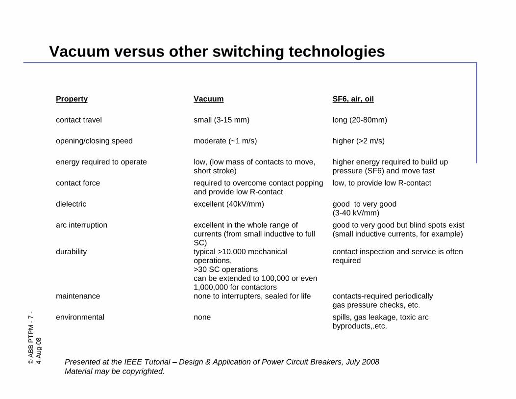
Vacuum versus other switching technologies
Property Vacuum SF6, air, oil
contact travel small (3-15 mm) long (20-80mm)
opening/closing speed moderate (~1 m/s) higher (>2 m/s)
energy required to operate low, (low mass of contacts to move,short stroke)
higher energy required to build uppressure (SF6) and move fast
contact force required to overcome contact poppingand provide low R-contact
low, to provide low R-contact
dielectric excellent (40kV/mm) good to very good(3-40 kV/mm)
arc interruption excellent in the whole range ofcurrents (from small inductive to fullSC)
good to very good but blind spots exist(small inductive currents, for example)
durability typical >10,000 mechanicaloperations,>30 SC operationscan be extended to 100,000 or even1,000,000 for contactors
contact inspection and service is oftenrequired
maintenance none to interrupters, sealed for life contacts-required periodicallygas pressure checks, etc.
environmental none spills, gas leakage, toxic arcbyproducts,.etc.
©AB
B PT
PM-8
-4-
Aug-
08
Presented at the IEEE Tutorial – Design & Application of Power Circuit Breakers, July 2008Material may be copyrighted.
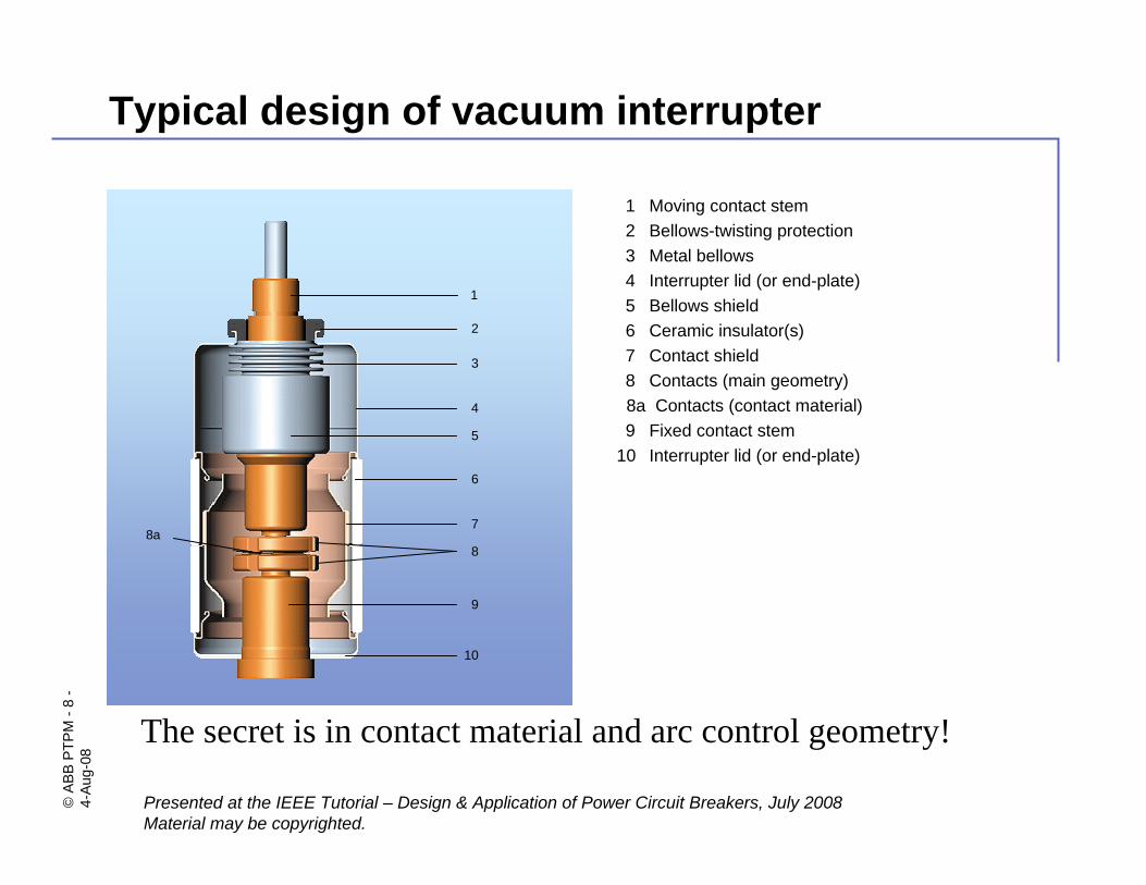
Typical design of vacuum interrupter
The secret is in contact material and arc control geometry!
1 Moving contact stem2 Bellows-twisting protection3 Metal bellows4 Interrupter lid (or end-plate)5 Bellows shield6 Ceramic insulator(s)7 Contact shield8 Contacts (main geometry)8a Contacts (contact material) 9 Fixed contact stem
10 Interrupter lid (or end-plate)
1
2
3
4
5
6
7
8
9
10
8a
©AB
B PT
PM-9
-4-
Aug-
08
Presented at the IEEE Tutorial – Design & Application of Power Circuit Breakers, July 2008Material may be copyrighted.
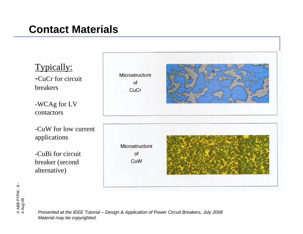
Contact Materials
Typically:-CuCr for circuit breakers
-WCAg for LV contactors
-CuW for low current applications
-CuBi for circuit breaker (second alternative)
©AB
B PT
PM-1
0-
4-Au
g-08
Presented at the IEEE Tutorial – Design & Application of Power Circuit Breakers, July 2008Material may be copyrighted.
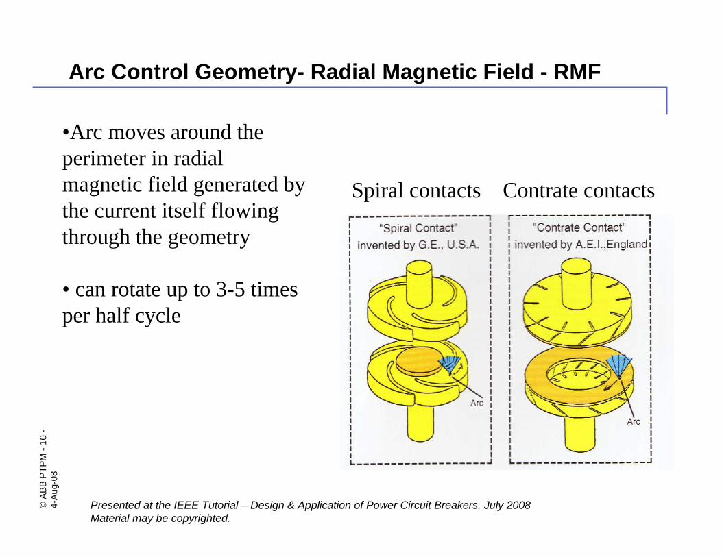
Arc Control Geometry- Radial Magnetic Field - RMF
•Arc moves around the perimeter in radial magnetic field generated by the current itself flowing through the geometry
• can rotate up to 3-5 times per half cycle
Spiral contacts Contrate contacts
©AB
B PT
PM-1
1-
4-Au
g-08
Presented at the IEEE Tutorial – Design & Application of Power Circuit Breakers, July 2008Material may be copyrighted.
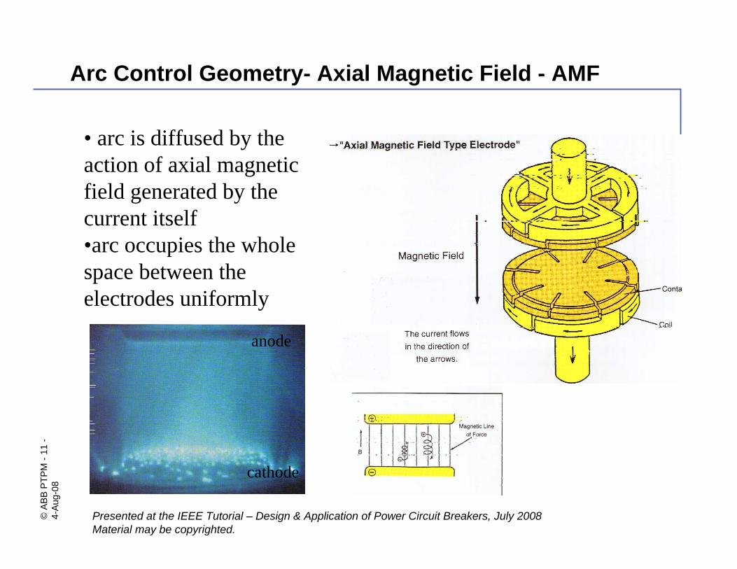
Arc Control Geometry- Axial Magnetic Field - AMF
• arc is diffused by the action of axial magnetic field generated by the current itself•arc occupies the whole space between the electrodes uniformly
cathode
anode

©AB
B PT
PM-1
2-
4-Au
g-08
Presented at the IEEE Tutorial – Design & Application of Power Circuit Breakers, July 2008Material may be copyrighted.
Manufacturing of Vacuum interrupters
©AB
B PT
PM-1
3-
4-Au
g-08
Presented at the IEEE Tutorial – Design & Application of Power Circuit Breakers, July 2008Material may be copyrighted.
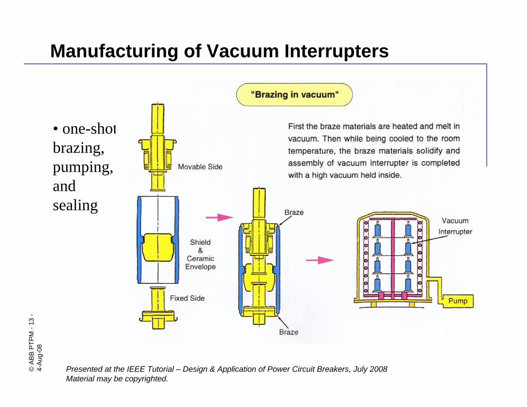
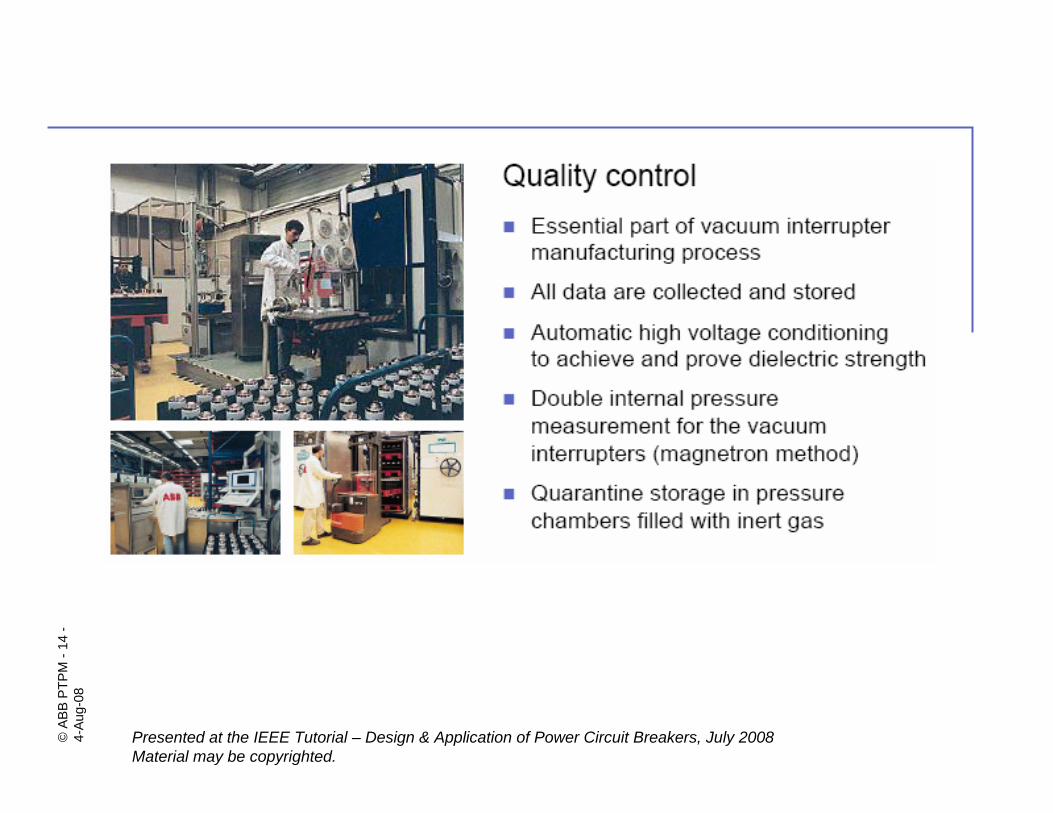
Manufacturing of Vacuum Interrupters
• one-shot brazing, pumping, and sealing
©AB
B PT
PM-1
4-
4-Au
g-08
Presented at the IEEE Tutorial – Design & Application of Power Circuit Breakers, July 2008Material may be copyrighted.
©AB
B PT
PM-1
5-
4-Au
g-08
Presented at the IEEE Tutorial – Design & Application of Power Circuit Breakers, July 2008Material may be copyrighted.
Vacuum interrupter.Design considerations.

©AB
B PT
PM-1
6-
4-Au
g-08
Presented at the IEEE Tutorial – Design & Application of Power Circuit Breakers, July 2008Material may be copyrighted.
VI Contact hardening (1)
No. of operations0 80 160
Amount of VI compression (Δ) in mm
Vary from fraction of mm to 1-2 mm
©AB
B PT
PM-1
7-
4-Au
g-08
Presented at the IEEE Tutorial – Design & Application of Power Circuit Breakers, July 2008Material may be copyrighted.
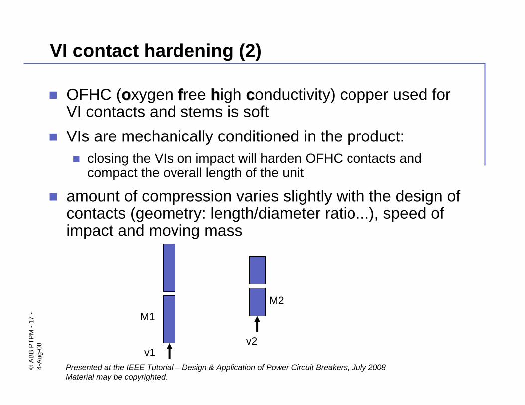
VI contact hardening (2)
OFHC (ooxygen ffree hhigh cconductivity) copper used for VI contacts and stems is softVIs are mechanically conditioned in the product:
closing the VIs on impact will harden OFHC contacts and compact the overall length of the unit
amount of compression varies slightly with the design of contacts (geometry: length/diameter ratio...), speed of impact and moving mass
M1
v1
M2
v2
©AB
B PT
PM-1
8-
4-Au
g-08
Presented at the IEEE Tutorial – Design & Application of Power Circuit Breakers, July 2008Material may be copyrighted.
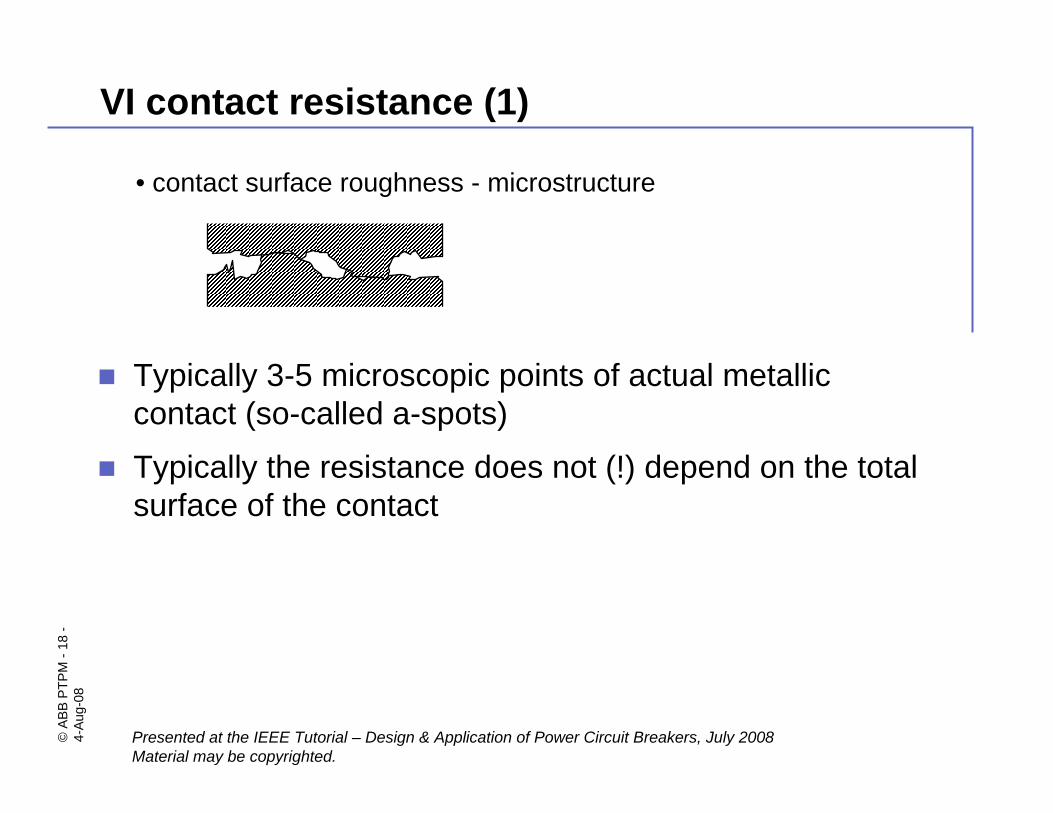
VI contact resistance (1)
• contact surface roughness - microstructure
Typically 3-5 microscopic points of actual metallic contact (so-called a-spots)
Typically the resistance does not (!) depend on the total surface of the contact

©AB
B PT
PM-1
9-
4-Au
g-08
Presented at the IEEE Tutorial – Design & Application of Power Circuit Breakers, July 2008Material may be copyrighted.
RC is contact resistance
ρ - electrical resistivity of the material
ζ - empirical factor between 0.1 and 0.3H - material hardness
F - contact force
Typically: Rc=2 μΩ to 20 μΩ for F= 3,000N - 6,000N
VI contact resistance (2) - formula
FHRC
ζπρ2
=
©AB
B PT
PM-2
0-
4-Au
g-08
Presented at the IEEE Tutorial – Design & Application of Power Circuit Breakers, July 2008Material may be copyrighted.
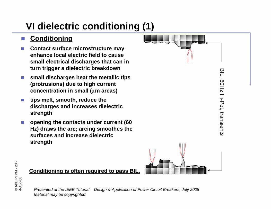
VI dielectric conditioning (1)ConditioningContact surface microstructure may enhance local electric field to cause small electrical discharges that can in turn trigger a dielectric breakdownsmall discharges heat the metallic tips (protrusions) due to high current concentration in small (μm areas)tips melt, smooth, reduce the discharges and increases dielectric strengthopening the contacts under current (60 Hz) draws the arc; arcing smoothes the surfaces and increase dielectric strength
BIL, 60H
z Hi-P
ot, transients
Conditioning is often required to pass BIL.Conditioning is often required to pass BIL.
©AB
B PT
PM-2
1-
4-Au
g-08
Presented at the IEEE Tutorial – Design & Application of Power Circuit Breakers, July 2008Material may be copyrighted.
VI dielectric deconditioning (2)
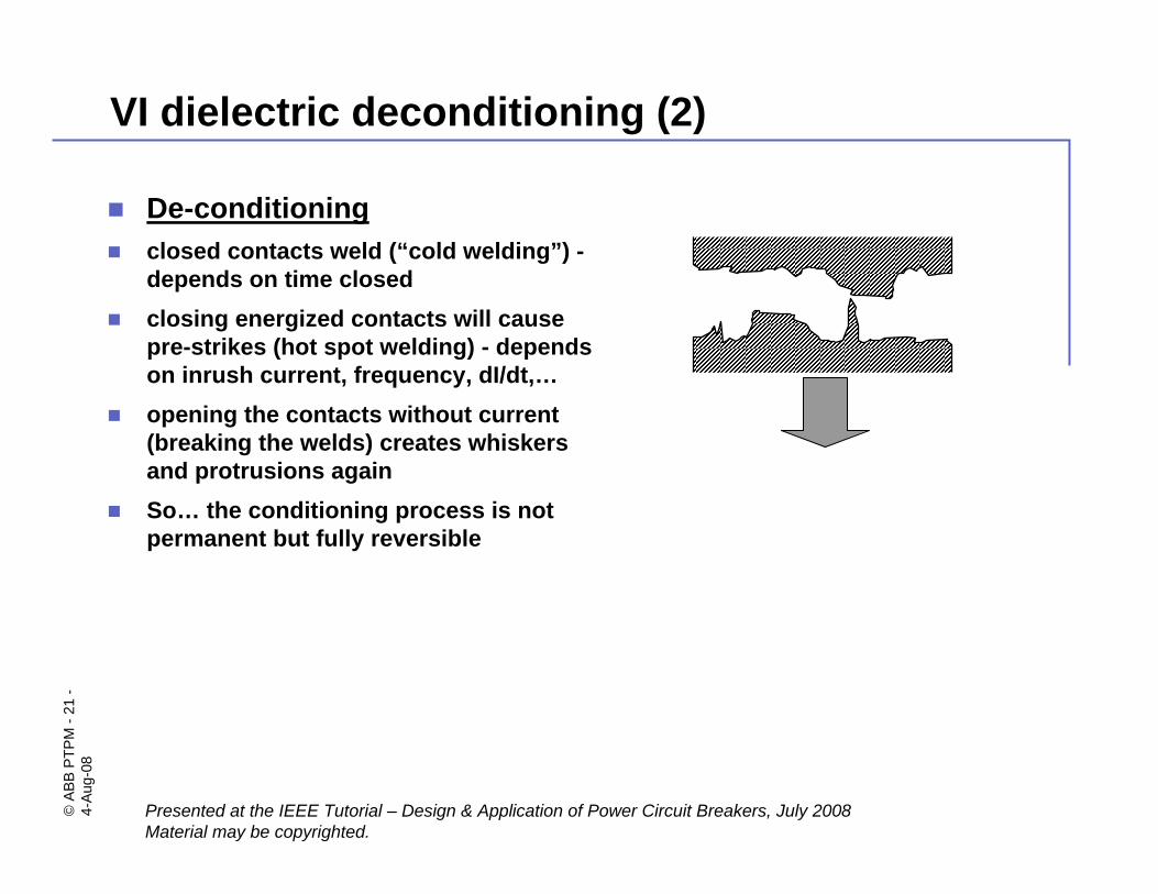
De-conditioningclosed contacts weld (“cold welding”) -depends on time closedclosing energized contacts will cause pre-strikes (hot spot welding) - depends on inrush current, frequency, dI/dt,…opening the contacts without current (breaking the welds) creates whiskers and protrusions againSo… the conditioning process is not permanent but fully reversible
©AB
B PT
PM-2
2-
4-Au
g-08
Presented at the IEEE Tutorial – Design & Application of Power Circuit Breakers, July 2008Material may be copyrighted.
VI useful life (1)
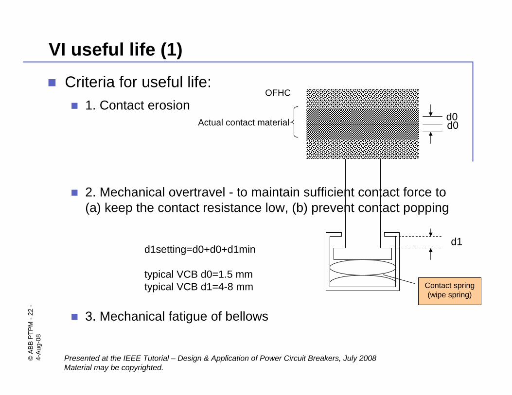
Criteria for useful life:1. Contact erosion
2. Mechanical overtravel - to maintain sufficient contact force to (a) keep the contact resistance low, (b) prevent contact popping
3. Mechanical fatigue of bellows
d0d0
d1d1setting=d0+d0+d1min
typical VCB d0=1.5 mmtypical VCB d1=4-8 mm
Actual contact material
OFHC
Contact spring (wipe spring)
©AB
B PT
PM-2
3-
4-Au
g-08
Presented at the IEEE Tutorial – Design & Application of Power Circuit Breakers, July 2008Material may be copyrighted.
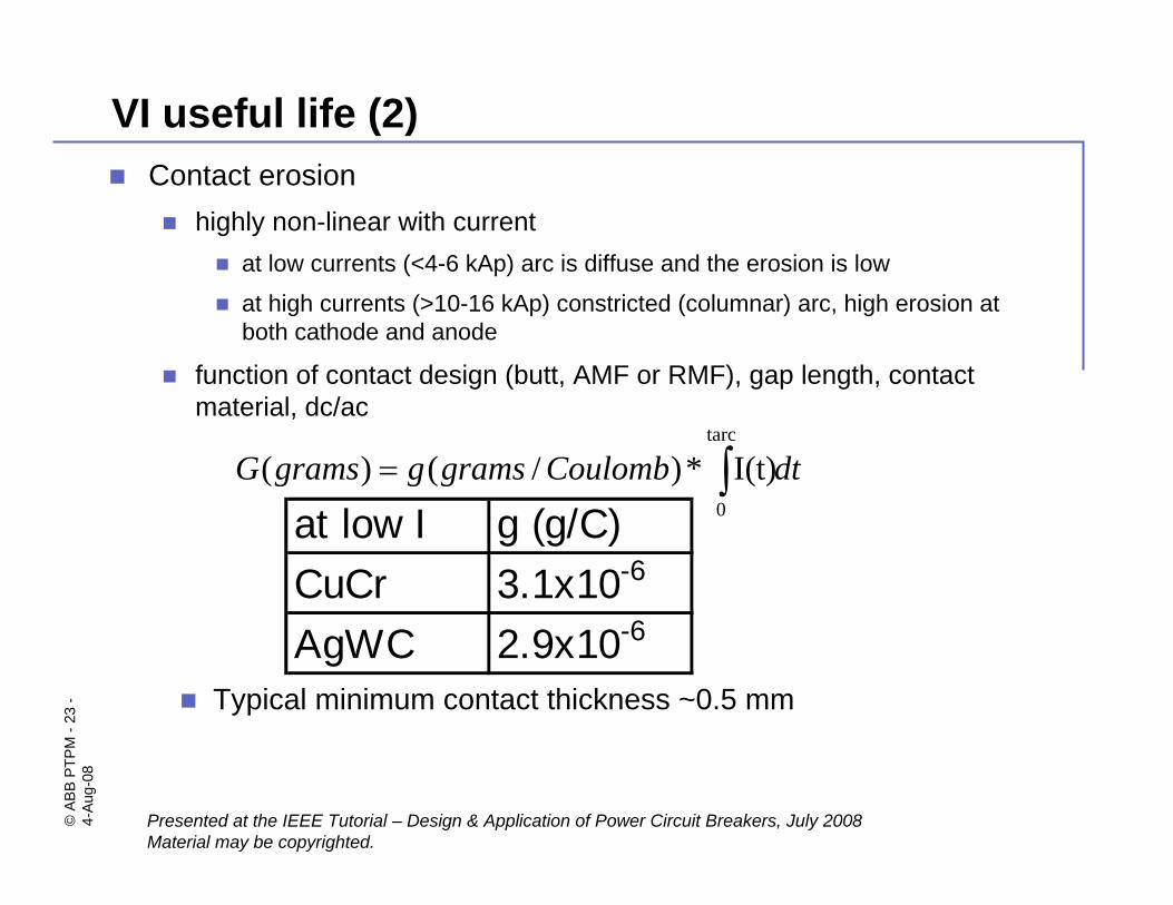
Contact erosionhighly non-linear with current
at low currents (<4-6 kAp) arc is diffuse and the erosion is low
at high currents (>10-16 kAp) constricted (columnar) arc, high erosion at both cathode and anode
function of contact design (butt, AMF or RMF), gap length, contact material, dc/ac
VI useful life (2)
dtCoulombgramsggramsG ∫=tarc
0
I(t)*)/()(
at low I g (g/C)CuCr 3.1x10⁻⁶
AgWC 2.9x10⁻⁶
Typical minimum contact thickness ~0.5 mm
©AB
B PT
PM-2
4-
4-Au
g-08
Presented at the IEEE Tutorial – Design & Application of Power Circuit Breakers, July 2008Material may be copyrighted.
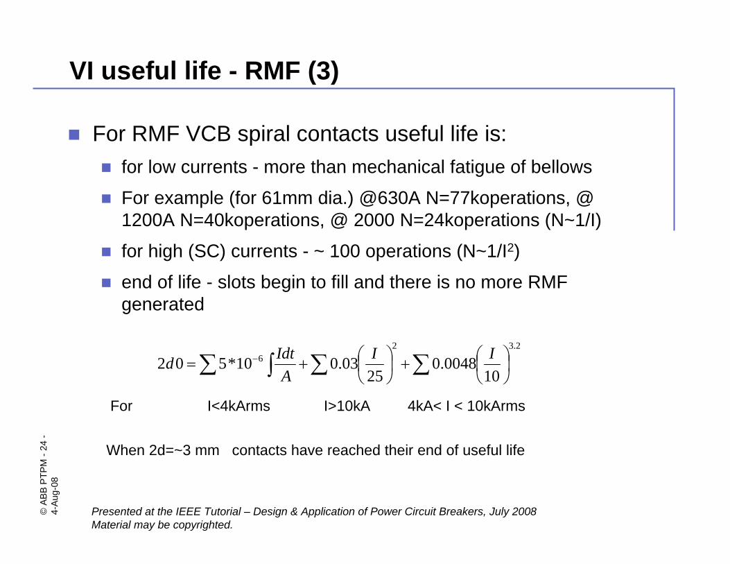
VI useful life - RMF (3)
For RMF VCB spiral contacts useful life is:for low currents - more than mechanical fatigue of bellows
For example (for 61mm dia.) @630A N=77koperations, @ 1200A N=40koperations, @ 2000 N=24koperations (N~1/I)
for high (SC) currents - ~ 100 operations (N~1/I2)
end of life - slots begin to fill and there is no more RMF generated
∑ ∫ ∑ ∑ ⎟⎠⎞
⎜⎝⎛+⎟
⎠⎞
⎜⎝⎛+= −
2.326
100048.0
2503.010*502 II
AIdtd
For I<4kArms I>10kA 4kA< I < 10kArms
When 2d=~3 mm contacts have reached their end of useful life
©AB
B PT
PM-2
5-
4-Au
g-08
Presented at the IEEE Tutorial – Design & Application of Power Circuit Breakers, July 2008Material may be copyrighted.
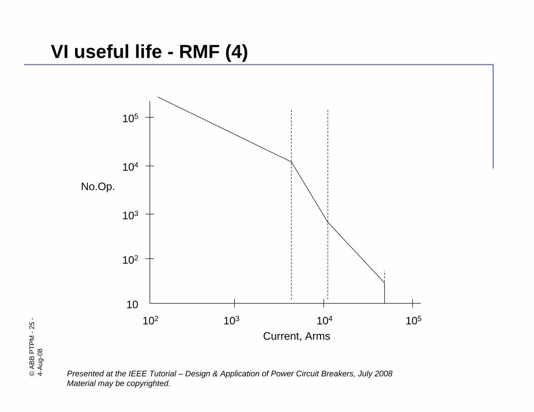
VI useful life - RMF (4)
102 103 104 105
Current, Arms
10
102
103
104
105
No.Op.
©AB
B PT
PM-2
6-
4-Au
g-08
Presented at the IEEE Tutorial – Design & Application of Power Circuit Breakers, July 2008Material may be copyrighted.
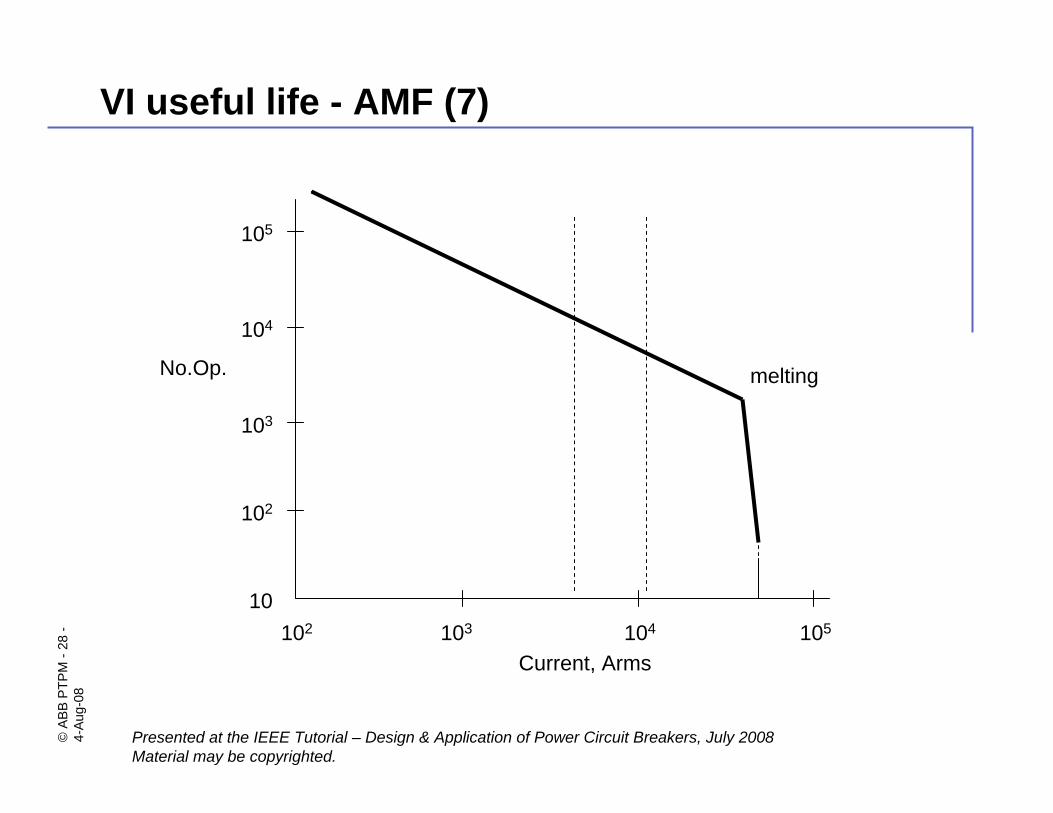
Lower mechanical stresses, less contact required
“normal” arcs are always diffuse (no columnar arc)
only at the initial stage of opening (very short gap) the short arcs are constricted, it takes a finite time (1-3 ms) to convert the arc to diffuse mode again
the limit for AMF is contact surface melting
VI useful life - AMF (5)
©AB
B PT
PM-2
7-
4-Au
g-08
Presented at the IEEE Tutorial – Design & Application of Power Circuit Breakers, July 2008Material may be copyrighted.
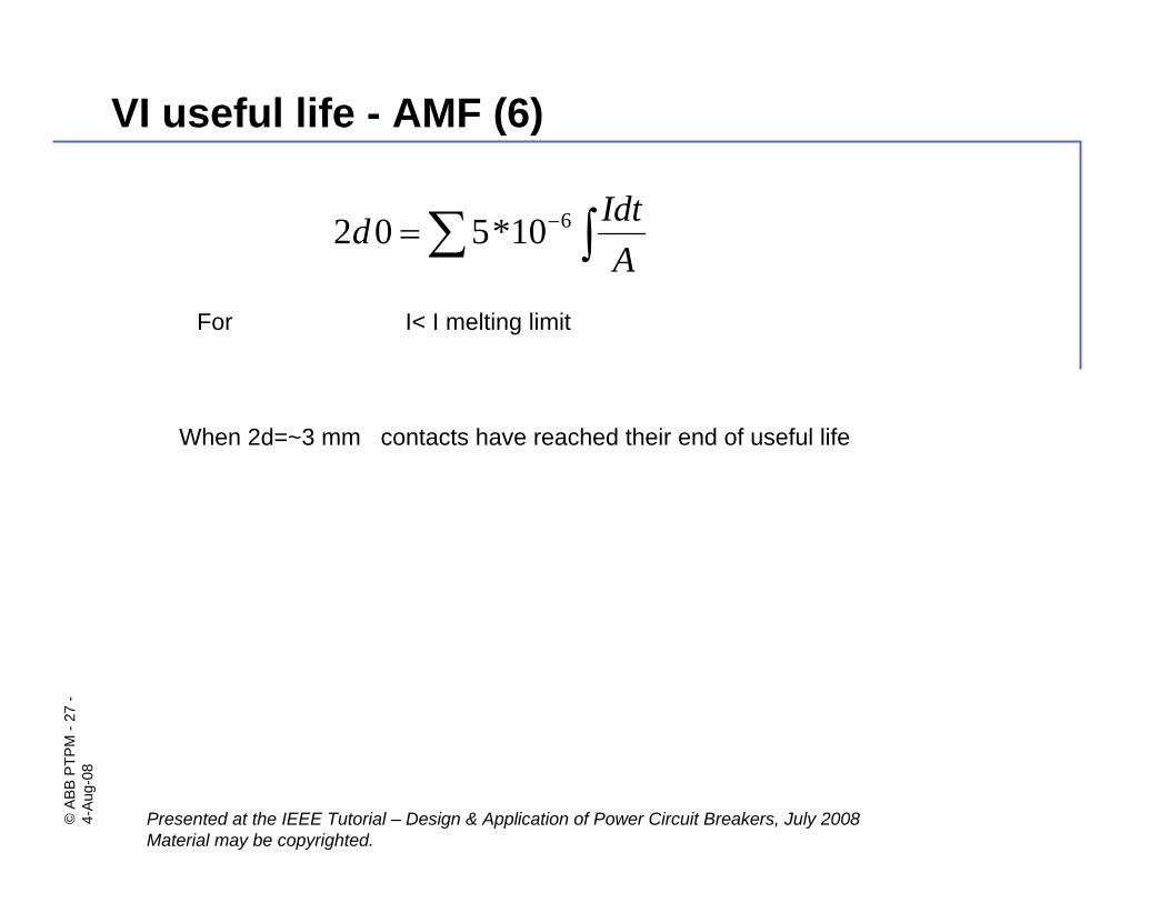
VI useful life - AMF (6)
∑ ∫−=A
Idtd 610*502
When 2d=~3 mm contacts have reached their end of useful life
For I< I melting limit
©AB
B PT
PM-2
8-
4-Au
g-08
Presented at the IEEE Tutorial – Design & Application of Power Circuit Breakers, July 2008Material may be copyrighted.
102 103 104 105
Current, Arms
10
102
103
104
105
No.Op.
VI useful life - AMF (7)
melting
©AB
B PT
PM-2
9-
4-Au
g-08
Presented at the IEEE Tutorial – Design & Application of Power Circuit Breakers, July 2008Material may be copyrighted.
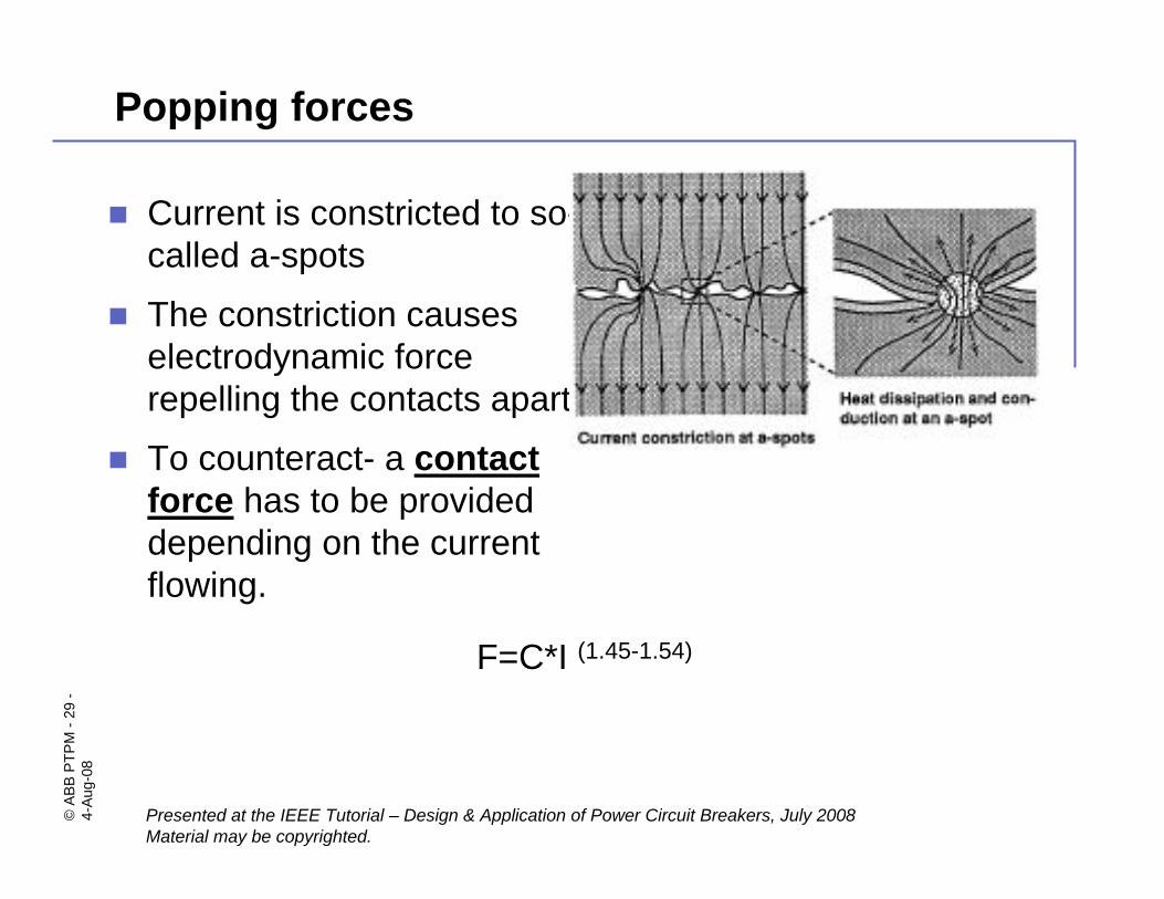
Current is constricted to so-called a-spots
The constriction causes electrodynamic force repelling the contacts apart
To counteract- a contact force has to be provided depending on the current flowing.
Popping forces
F=C*I (1.45-1.54)
©AB
B PT
PM-3
0-
4-Au
g-08
Presented at the IEEE Tutorial – Design & Application of Power Circuit Breakers, July 2008Material may be copyrighted.
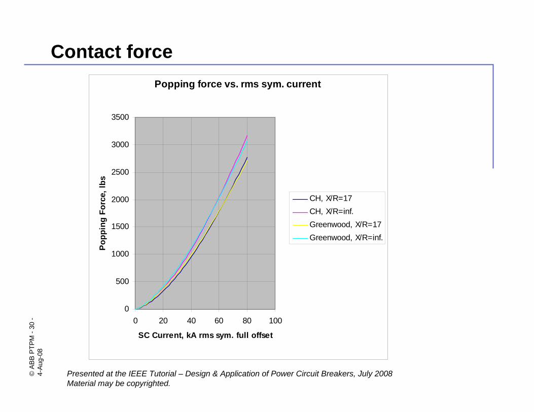
Contact forcePopping force vs. rms sym. current
0
500
1000
1500
2000
2500
3000
3500
0 20 40 60 80 100
SC Current, kA rms sym. full offset
Popp
ing
Forc
e, lb
s
CH, X/R=17CH, X/R=inf.Greenwood, X/R=17Greenwood, X/R=inf.
©AB
B PT
PM-3
1-
4-Au
g-08
Presented at the IEEE Tutorial – Design & Application of Power Circuit Breakers, July 2008Material may be copyrighted.
Dr. Mietek GlinkowskiDr. Mietek Glinkowskitel: 919-856-3861
©AB
B PT
PM-3
2-
4-Au
g-08
Presented at the IEEE Tutorial – Design & Application of Power Circuit Breakers, July 2008Material may be copyrighted.
Vacuum interrupter based devices.
©AB
B PT
PM-3
3-
4-Au
g-08
Presented at the IEEE Tutorial – Design & Application of Power Circuit Breakers, July 2008Material may be copyrighted.
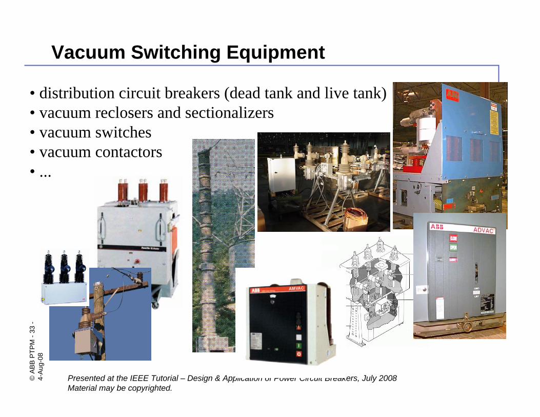
Vacuum Switching Equipment
• distribution circuit breakers (dead tank and live tank)• vacuum reclosers and sectionalizers• vacuum switches• vacuum contactors• ...
©AB
B PT
PM-3
4-
4-Au
g-08
Presented at the IEEE Tutorial – Design & Application of Power Circuit Breakers, July 2008Material may be copyrighted.
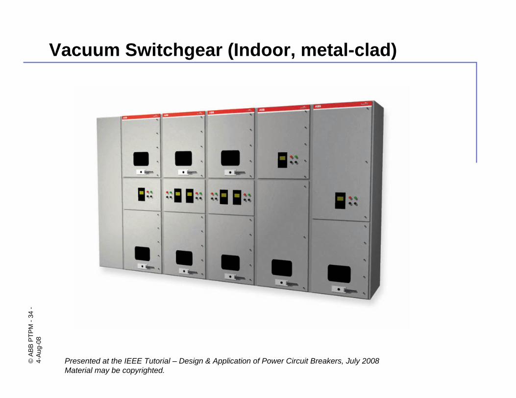
Vacuum Switchgear (Indoor, metal-clad)
©AB
B PT
PM-3
5-
4-Au
g-08
Presented at the IEEE Tutorial – Design & Application of Power Circuit Breakers, July 2008Material may be copyrighted.
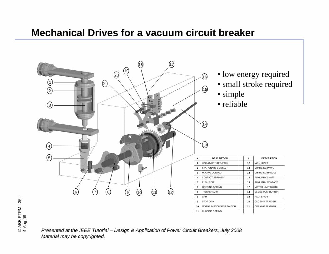
Mechanical Drives for a vacuum circuit breaker
6 7 8 1110 12
15
14
5
4
3
2
1
9
21
2019
18 17
16
13
# DESCRIPTION # DESCRIPTION
1 VACUUM INTERRUPTER 12 MAIN SHAFT
2 STATIONARY CONTACT 13 CHARGING PAWL
3 MOVING CONTACT 14 CHARGING HANDLE
4 CONTACT SPRINGS 15 AUXILIARY SHAFT
5 PUSH ROD 16 AUXILIARY CONTACT
6 OPENING SPRING 17 MOTOR LIMIT SWITCH
7 ROCKER ARM 18 CLOSE PUSHBUTTON
8 CAM 19 HALF SHAFT
9 STOP DISK 20 CLOSING TRIGGER
10 MOTOR DISCONNECT SWITCH 21 OPENING TRIGGER
11 CLOSING SPRING
• low energy required• small stroke required• simple• reliable
©AB
B PT
PM-3
6-
4-Au
g-08
Presented at the IEEE Tutorial – Design & Application of Power Circuit Breakers, July 2008Material may be copyrighted.
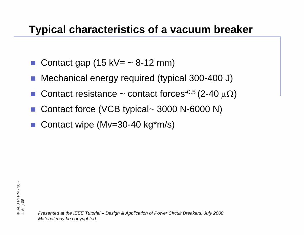
Typical characteristics of a vacuum breaker
Contact gap (15 kV= ~ 8-12 mm)
Mechanical energy required (typical 300-400 J)
Contact resistance ~ contact forces-0.5 (2-40 μΩ)Contact force (VCB typical~ 3000 N-6000 N)
Contact wipe (Mv=30-40 kg*m/s)
©AB
B PT
PM-3
7-
4-Au
g-08
Presented at the IEEE Tutorial – Design & Application of Power Circuit Breakers, July 2008Material may be copyrighted.
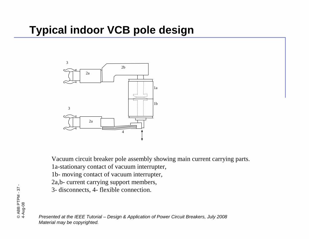
Typical indoor VCB pole design
1a
2b3
4
1b3
2a
2a
Vacuum circuit breaker pole assembly showing main current carrying parts.1a-stationary contact of vacuum interrupter,1b- moving contact of vacuum interrupter,2a,b- current carrying support members,3- disconnects, 4- flexible connection.
©AB
B PT
PM-3
8-
4-Au
g-08
Presented at the IEEE Tutorial – Design & Application of Power Circuit Breakers, July 2008Material may be copyrighted.
Summary, conclusions and future trends.
©AB
B PT
PM-3
9-
4-Au
g-08
Presented at the IEEE Tutorial – Design & Application of Power Circuit Breakers, July 2008Material may be copyrighted.
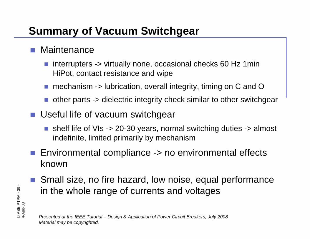
Summary of Vacuum SwitchgearMaintenance
interrupters -> virtually none, occasional checks 60 Hz 1min HiPot, contact resistance and wipe
mechanism -> lubrication, overall integrity, timing on C and O
other parts -> dielectric integrity check similar to other switchgear
Useful life of vacuum switchgearshelf life of VIs -> 20-30 years, normal switching duties -> almost indefinite, limited primarily by mechanism
Environmental compliance -> no environmental effects known
Small size, no fire hazard, low noise, equal performance in the whole range of currents and voltages
©AB
B PT
PM-4
0-
4-Au
g-08
Presented at the IEEE Tutorial – Design & Application of Power Circuit Breakers, July 2008Material may be copyrighted.
Safety and Reliability
No exposure to arcs or arc byproducts
If overloaded vacuum interrupter fails in benign way
SafetyWhen high voltage is applied between two electrodes in vacuum environment a small electron emission current results. The cathodic electrons bombarding the surface of the opposite anode can generate small amount of X-ray emission. Under normal circumstances, i.e. within the voltage rating of the device and at the full open gap the X-ray emission is minimal. However, when the device is tested or operated at a fractional gap distance the excessive voltage may cause more X-rays. In such cases most manufacturers of vacuum switches warn the users of the exposure and recommend that a protective lead shield, or equivalent means, be used if any personnel be working close to the vacuum chamber for prolonged period of time. Normally, standard safety distances for electrical reasons are sufficient.
Reliability
Vacuum interrupters are sealed for life. Typical defect rate for good interrupters is ~10-6 (1 per million)
©AB
B PT
PM-4
1-
4-Au
g-08
Presented at the IEEE Tutorial – Design & Application of Power Circuit Breakers, July 2008Material may be copyrighted.
Trends in Vacuum Switchgear Technology
Simplified mechanical drivelower energy drives, magnetic actuation, faster/more accurate operation
Higher voltage ratingstrends to extend to 69/72 kV and 138/145 kV
Higher interrupting current ratingsoptimization of contact design, better utilization of magnetic fields (AMF and RMF), new way of utilizing magnetic fields
Intelligent switchingClosing and opening on point of wave, independent pole operation, suitable for Distribution Automation, VCB controllers tailored to specific applications
Encapsulationreduce VI size (outside ceramic), no serviceable parts, better mechanical strength, resistance to shocks and weather
©AB
B PT
PM-4
2-
4-Au
g-08
Presented at the IEEE Tutorial – Design & Application of Power Circuit Breakers, July 2008Material may be copyrighted.
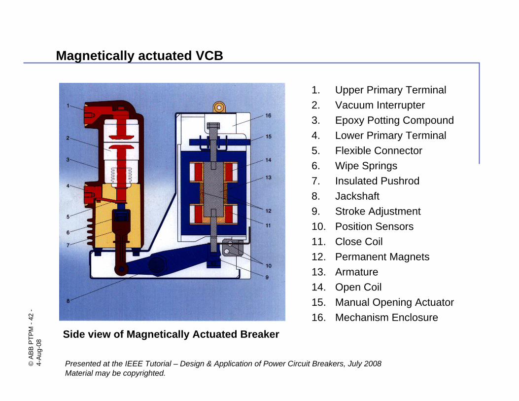
Magnetically actuated VCB
1. Upper Primary Terminal2. Vacuum Interrupter3. Epoxy Potting Compound4. Lower Primary Terminal5. Flexible Connector6. Wipe Springs7. Insulated Pushrod8. Jackshaft9. Stroke Adjustment10. Position Sensors11. Close Coil12. Permanent Magnets13. Armature14. Open Coil15. Manual Opening Actuator16. Mechanism Enclosure
Side view of Magnetically Actuated Breaker
©AB
B PT
PM-4
3-
4-Au
g-08
Presented at the IEEE Tutorial – Design & Application of Power Circuit Breakers, July 2008Material may be copyrighted.
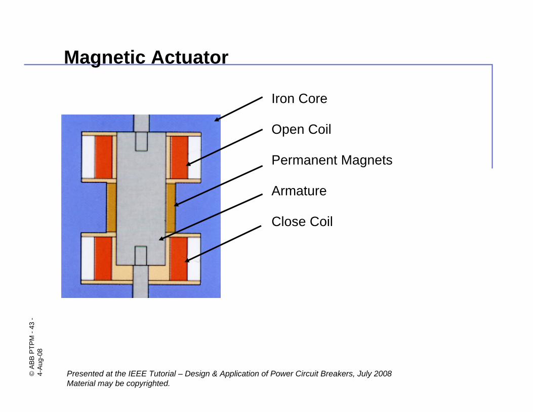
Magnetic Actuator
Iron Core
Open Coil
Permanent Magnets
Armature
Close Coil
©AB
B PT
PM-4
4-
4-Au
g-08
Presented at the IEEE Tutorial – Design & Application of Power Circuit Breakers, July 2008Material may be copyrighted.
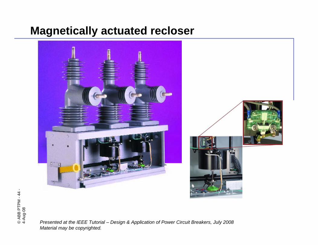
Magnetically actuated recloser