
Computer analysis of saturated cage induction machine ...
16
* Dr hab. inż. Piotr Drozdowski, prof. PK, mgr inż. Arkadiusz Duda, Instytut Elektromechanicznych Przemian Energii, Wydział Inżynierii Elektrycznej i Komputerowej, Politechnika Krakowska. PIOTR DROZDOWSKI, ARKADIUSZ DUDA* COMPUTER ANALYSIS OF SATURATED CAGE INTRODUCTION MACHINE USING SIM-POWER-SYSTEMS OF SIMULINK ANALIZA KOMPUTEROWA NASYCONEJ MASZYNY INDUKCYJNEJ KLATKOWEJ ZA POMOCĄ SIM-POWER-SYSTEMS PAKIETU SIMULINK Abstract In this paper the computer model of the cage induction machine taking into account magnetic non-linearity is presented. The model contains the mathematical model of the induction machine recorded as an S-function and the connecting blocs attaching the model from one side to the three-phase terminals of the supply system model and from the other to the system of mechanical model. Hence, Sim-Power-Systems and Sim-Mechanics libraries can be used. Such a methodology allows for various drives modelling where the induction machine operates as a motor or a generator and cooperates with power electronics system. Using wide range of SIMULINK possibilities the various control techniques can be applied. Using this methodology the own mathematical models of other electrical machines together with the SIMULINK library models can be used. Keywords: Induction machine modelling, Magnetic saturation, MATLAB-SIMULINK, Sim-Power-Systems Streszczenie Przedstawiono model komputerowy klatkowej maszyny indukcyjnej uwzględniający nieliniowość magnetyczną. Maszyna indukcyjna jest modelowana za pomocą bloku tzw. S-funkcji dołączonego, z jednej strony, do trójfazo- wego zasilania przez blok sterowanych źródeł napięcia i prądu, a z drugiej ‒ do modelu układu mechanicznego. Umożliwia to wykorzystanie biblioteki modeli z grupy Sim-Power-Systems i grupy Sim-Mechanics. Takie po- dejście umożliwia modelowanie pracy maszyny indukcyjnej współpracującej z układami energoelektrycznymi jako silnika i pradnicy. Stwarza to możliwości szerokiego wykorzystania potencjału Simulinka, w szczególności różnych technik sterowania układami. Zastosowana metodologia pozwala tworzyć własne modele innych maszyn elektrycznych opisanych tradycyjnie blokiem równań różniczkowych i wykorzystanie bogatej biblioteki Simu- linka. Słowa kluczowe: modelowanie maszyny indukcyjnej, nasycenie magnetyczne, MATLAB-SIMULINK, Sim-Power- Systems
Transcript of Computer analysis of saturated cage induction machine ...
* Dr hab. inż. Piotr Drozdowski, prof. PK, mgr inż. Arkadiusz Duda, Instytut Elektromechanicznych Przemian Energii, Wydział Inżynierii Elektrycznej i Komputerowej, Politechnika Krakowska.
PIOTR DROZDOWSKI, ARKADIUSZ DUDA*
COMPUTER ANALYSIS OF SATURATED CAGE INTRODUCTION MACHINE USING
SIM-POWER-SYSTEMS OF SIMULINK
ANALIZA KOMPUTEROWA NASYCONEJ MASZYNY INDUKCYJNEJ KLATKOWEJ ZA POMOCĄ
SIM-POWER-SYSTEMS PAKIETU SIMULINKA b s t r a c t
In this paper the computer model of the cage induction machine taking into account magnetic non-linearity is presented. The model contains the mathematical model of the induction machine recorded as an S-function and the connecting blocs attaching the model from one side to the three-phase terminals of the supply system model and from the other to the system of mechanical model. Hence, Sim-Power-Systems and Sim-Mechanics libraries can be used. Such a methodology allows for various drives modelling where the induction machine operates as a motor or a generator and cooperates with power electronics system. Using wide range of SIMULINK possibilities the various control techniques can be applied. Using this methodology the own mathematical models of other electrical machines together with the SIMULINK library models can be used.
Keywords: Induction machine modelling, Magnetic saturation, MATLAB-SIMULINK, Sim-Power-Systems
S t r e s z c z e n i ePrzedstawiono model komputerowy klatkowej maszyny indukcyjnej uwzględniający nieliniowość magnetyczną. Maszyna indukcyjna jest modelowana za pomocą bloku tzw. S-funkcji dołączonego, z jednej strony, do trójfazo-wego zasilania przez blok sterowanych źródeł napięcia i prądu, a z drugiej ‒ do modelu układu mechanicznego. Umożliwia to wykorzystanie biblioteki modeli z grupy Sim-Power-Systems i grupy Sim-Mechanics. Takie po-dejście umożliwia modelowanie pracy maszyny indukcyjnej współpracującej z układami energoelektrycznymi jako silnika i pradnicy. Stwarza to możliwości szerokiego wykorzystania potencjału Simulinka, w szczególności różnych technik sterowania układami. Zastosowana metodologia pozwala tworzyć własne modele innych maszyn elektrycznych opisanych tradycyjnie blokiem równań różniczkowych i wykorzystanie bogatej biblioteki Simu-linka.
Słowa kluczowe: modelowanie maszyny indukcyjnej, nasycenie magnetyczne, MATLAB-SIMULINK, Sim-Power-Systems
34
1. Introduction
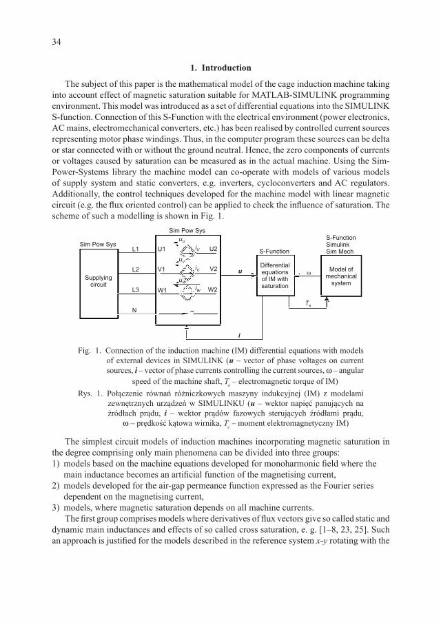
The subject of this paper is the mathematical model of the cage induction machine taking into account effect of magnetic saturation suitable for MATLAB-SIMULINK programming environment. This model was introduced as a set of differential equations into the SIMULINK S-function. Connection of this S-Function with the electrical environment (power electronics, AC mains, electromechanical converters, etc.) has been realised by controlled current sources representing motor phase windings. Thus, in the computer program these sources can be delta or star connected with or without the ground neutral. Hence, the zero components of currents or voltages caused by saturation can be measured as in the actual machine. Using the Sim-Power-Systems library the machine model can co-operate with models of various models of supply system and static converters, e.g. inverters, cycloconverters and AC regulators. Additionally, the control techniques developed for the machine model with linear magnetic circuit (e.g. the flux oriented control) can be applied to check the influence of saturation. The scheme of such a modelling is shown in Fig. 1.
Fig. 1. Connection of the induction machine (IM) differential equations with models of external devices in SIMULINK (u – vector of phase voltages on current sources, i – vector of phase currents controlling the current sources, w – angular
speed of the machine shaft, Te – electromagnetic torque of IM)Rys. 1. Połączenie równań różniczkowych maszyny indukcyjnej (IM) z modelami
zewnętrznych urządzeń w SIMULINKU (u ‒ wektor napięć panujących na źródłach prądu, i ‒ wektor prądów fazowych sterujących źródłami prądu,
w ‒ prędkość kątowa wirnika, Te ‒ moment elektromagnetyczny IM)
The simplest circuit models of induction machines incorporating magnetic saturation in the degree comprising only main phenomena can be divided into three groups: 1) models based on the machine equations developed for monoharmonic field where the
main inductance becomes an artificial function of the magnetising current, 2) models developed for the air-gap permeance function expressed as the Fourier series
dependent on the magnetising current,3) models, where magnetic saturation depends on all machine currents.
The first group comprises models where derivatives of flux vectors give so called static and dynamic main inductances and effects of so called cross saturation, e. g. [1–8, 23, 25]. Such an approach is justified for the models described in the reference system x-y rotating with the
35
speed of any machine vector, e. g. the vector of magnetising current, since, this is in fact the DC machine. Models of the second group are based on the assumption that the fundamental harmonic of magnetic field changes seemingly the air gap of the machine from smooth to salient increasing artificially the air-gap length in places where the field crosses from the stator to the rotor [12, 13]. Such an approach allows for extension of the monoharmonic model with the effect of third harmonic of the magnetic field. The varying air-gap was also used to formulate the multi-harmonic model of the induction machine. The varying permeance of the non-uniform air-gap was used to calculate winding inductances dependent on the magnetising current using formulae presented in [14]. The permeance harmonics of the Fourier series approximation depend on resulting MMF or on equivalent magnetising current [11, 15, 16, 26]. For example the influence of slotting or rotor eccentricity can be included into this model and additionally the influence of saturation on leakage inductances [18]. However, neglecting higher harmonics the model assumes the simplest form as for the first group. The circuit models from the third group, presenting the most general approach [10, 17, 19, 20, 24, 27], are based on expressions approximating winding fluxes dependent on all machine currents utilising function of magnetic co-energy. To obtain useful mathematical models the magnetising current was also used in this method.
In this paper the machine model descends from the second group. The first attempt to connect it with models of external devices was published in [26] for SPICE family programs. All terminals of the stator winding were there available to connect with models of static converters or other supply systems. Other approach was presented in [22], though that model also allows for magnetic non-linearity modelling and has three stator terminals for connection with a supply system model. However, modelling in SIPCE has some disadvantages appearing in difficult modelling of control system comprising digital subsystems, observers, adaptive controllers, etc. Adapting the machine model to MATLAB-SIMULINK gives the possibility to overcome these limitations. Thus, this is the main subject of this paper.
2. Mathematical description of the induction machine
The voltage equations of an induction machine take the known form in natural components for each winding and can be written using the matrix description:
U0
R
R
I
Is s
r
s
r
s
rt
I I
I
I
I
I
I
dd
=
+
ΨΨ
ΨΨ (1)
The superscript “I” indicates that this is the beginning form before transformation to symmetrical components or space vectors, where the superscript will be “II”. In the above:
Us U V WTu u uI = [ ] , Is U V W
Ti i iI = [ ] - vectors of stator voltages and stator currents
respectively, Ir NTi i i iI = [ ]1 2 3 ... - vector of rotor cage mesh currents, ΨΨs U V W
TI = [ ]ψ ψ ψ
- vector of stator phase flux linkages, ΨΨr NTI = [ ]ψ ψ ψ ψ1 2 3 ... - vector of rotor cage mesh
flux linkages, RsI - matrix of stator phase resistances, Rr
I - matrix of resistances of rotor cage elements (bars and end segments).
36
For the machine with a non-linear ferromagnetic core the flux linkages are non-linear functions of all winding currents and the mutual position of these stator and rotor windings. Thus, saturation of the magnetic core can be considered as a function of total MMF q [20] produced by all the windings (for the stator qs and for the rotor qr). The greatest influence has the fundamental harmonic q1 of MMF. This part of MMF, producing the field having pole pair number p, is a function of the angle x, calculated along the air gap of the machine cross section, and the magnitude qm [21]:
θ θ θ θ α1 1 1( ) ( ) ( ) cos ( )x x x p xs r m m= + = − (2)
The MMF magnitude can be equivalently substituted by the magnitude im of resulting
magnetising current according to the relationship θπmw w
mN kpi= 2 3 . The parameters:
Nw - number of stator winding turns, kw - stator winding factor for fundamental harmonic. The first maximum of MMF fundamental harmonic is in the place am. Hence, the permeance appears as the response of exciting MMF described by (2). The field crosses the air gap in 2p places. Thus, the permeance function can take the simplest description incorporating effect of magnetic saturation and can be described by the Fourier series [11, 15, 16, 26]:
Λ Λ Λ Λ= − ==∑o pu
m m oo c ci p xR lpµ
µ
µ αµ
π δ( ) cos[ ( )];
,0 22
4 (3)
In the above:mo = 4p · 10–7 H/m,Rc - inside stator radius,lc - equivalent length of the machine core,δ - air-gap equivalent length.
Thus, the inductances of the machine can be formulated using formulae presented in [14]. According to that, the MMF harmonics must satisfy the following relationship for their orders n and r:
ν ρ µ± = (4)
These harmonic numbers belong to one set H determining accuracy of MMF approximation, where: n ∈ H denotes MMF harmonic order produced by winding “a”, r ∈ H denotes MMF harmonic order of winding “b” and m ∈ Hm = {0,2}is the harmonic order of permeance function (3). For one winding “a” and “b” mean the same. For the model presented in this paper the lowest possible set H = {1, 3} has been taken into account. The coefficient Q = 1 indicates that equation (4) is satisfied. Otherwise Q = 0. Hence, the following threes of n, r, m: (1, 1, 0), (1, 1, 2), (1, 3, 2), (3, 1, 2), (3, 3, 0) give Q = 1.
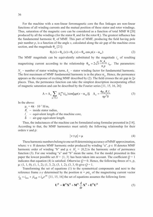
Transforming the set of equations (1) to the symmetrical components and next to the reference frame x-y determined by the position a = pam of the magnetising current vector i i ji i em m m m
j= + =α βα [11, 15, 16] the set of equations assumes the following form:
U R X M X E UII II II II II II IIdd
= + +t
(5)
37
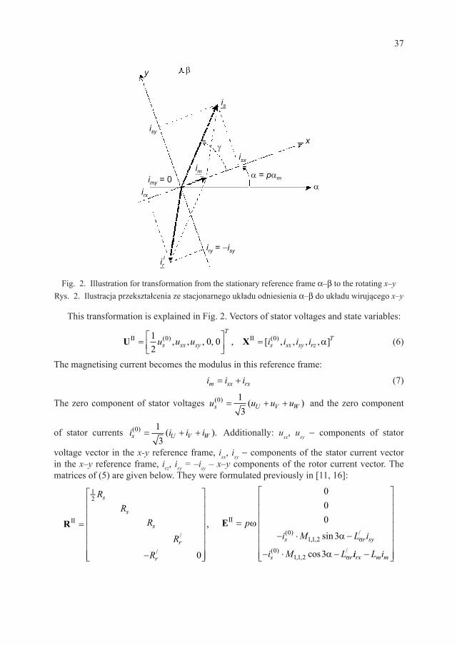
Fig. 2. Illustration for transformation from the stationary reference frame a–b to the rotating x–yRys. 2. Ilustracja przekształcenia ze stacjonarnego układu odniesienia a–b do układu wirującego x–y
This transformation is explained in Fig. 2. Vectors of stator voltages and state variables:
UII II=
=12
0 00 0u u u i i i is sx sy
T
s sx sy rzT( ) ( ), , , , , [ , , , , ]X α (6)
The magnetising current becomes the modulus in this reference frame:
i i im sx rx= + (7)
The zero component of stator voltages u u u us U V W( ) ( )0 1
3= + + and the zero component
of stator currents i i i is U V W( ) ( ).0 1
3= + + Additionally: usx, usy - components of stator
voltage vector in the x-y reference frame, isx, isy - components of the stator current vector in the x–y reference frame, irz, iry = –isy – x–y components of the rotor current vector. The matrices of (5) are given below. They were formulated previously in [11, 16]:
RII =
−
12
0
RR
R
R
R
s
s
s
r
r
/
/
, EII =− ⋅ −
− ⋅ −
pi M L i
i M Ls r sy
s r
ωα
α
σ
σ
000
3
3
011 2
011 2
( ), ,
/
( ), ,
/
sin
cos ii L irx m m−
38
1,1,2 3,3,0 1,1,2 3,3,0(0) (0) (0)3,3,0 1,1,2 1,1,2
1,1,2 1,1,2(0) (0)1,1,2
II1,1,2
1 cos3 0 cos32
cos3 cos3 0 cos3
s
s m s m sm m m m
m ms m m s m m s
m m m m
M M M ML M M i i M i i
i i i iM ML L
M L L i i L i ii i i i
M
σ
σ
∂ ∂ ∂ ∂ + + α + + α + ∂ ∂ ∂ ∂
∂ ∂∂ ∂α + + + α + + α
∂ ∂ ∂ ∂
−=M 1,1,2 1,1,2(0) (0)
1,1,2 1,1,2(0) / (0)1,1,2
1,1,2 1,1,2(0) / (0)1,1,2
in 3 sin 3 sin 3
cos3 cos3 0 cos3
sin 3 sin 3 sin 3
s s sm m
m mm m s r m m s
m m m m
s r sm m
M Mi L i
i iM ML L
M L i i L L i ii i i iM M
M i L ii i
σ
σ
σ
∂ ∂ α − α − α ∂ ∂
∂ ∂∂ ∂α + + α + + + α
∂ ∂ ∂ ∂
∂ ∂− α − α − − α
∂ ∂
1,1,2(0)
1,1,2
(0)1,1,2
(0) /1,1,2
(0) /1,1,2
3 sin 3
2 sin 3
2 cos3
2 sin 3
2 cos3
m
s s sy
s s sx m m
s r sy
s r rx m m
i M
i M L i
i M L i L i
i M L i
i M L i L i
σ
σ
σ
σ
− ⋅ α
− ⋅ α −
− ⋅ α + + − ⋅ α + − ⋅ α + +
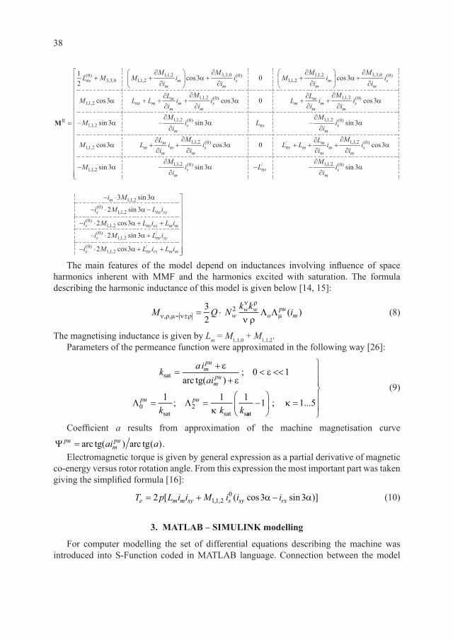
The main features of the model depend on inductances involving influence of space harmonics inherent with MMF and the harmonics excited with saturation. The formula describing the harmonic inductance of this model is given below [14, 15]:
M Q Nk k
iww w
opu
mν ρ µ ν ρ
ν ρ
µν ρ, , ( )= ± = ⋅32
2 Λ Λ (8)
The magnetising inductance is given by Lm = M1,1,0 + M1,1,2.Parameters of the permeance function were approximated in the following way [26]:
k
a iai
k k k
mpu
mpu
pu pu
sat
sat sat s
arc=
+
+< <<
= =
ε
εε
κ
tg( );
;
0 1
1 1 10 2Λ Λ
aat−
=
1 1 5; ...κ
(9)
Coefficient a results from approximation of the machine magnetisation curve
Ψ pumpuai a= arc arctg( ) tg( ).
Electromagnetic torque is given by general expression as a partial derivative of magnetic co-energy versus rotor rotation angle. From this expression the most important part was taken giving the simplified formula [16]:
T p L i i M i i ie m m sy s sy rx= + −2 3 311 20[ ( cos sin )], , α α (10)
3. MATLAB – SIMULINK modelling
For computer modelling the set of differential equations describing the machine was introduced into S-Function coded in MATLAB language. Connection between the model
39
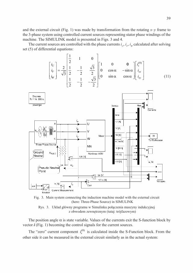
and the external circuit (Fig. 1) was made by transformation from the rotating x–y frame to the 3-phase system using controlled current sources representing stator phase windings of the machine. The SIMULINK model is presented in Figs. 3 and 4.
The current sources are controlled with the phase currents iU, iV, iW calculated after solving set (5) of differential equations:
iii
U
V
W
= −
− −
23
12
1 0
12
12
32
12
12
32
1 0 0000
0
cos sinsin cos
( )
α αα α
−
iii
s
sx
sy (11)
Fig. 3. Main system connecting the induction machine model with the external circuit (here: Three-Phase Source) in SIMULINK
Rys. 3. Układ główny programu w Simulinku połączenia maszyny indukcyjnej z obwodem zewnętrznym (tutaj: trójfazowym)
The position angle a is state variable. Values of the currents exit the S-function block by vector i (Fig. 1) becoming the control signals for the current sources.
The “zero” current component is( )0 is calculated inside the S-Function block. From the
other side it can be measured in the external circuit similarly as in the actual system:

40
– by neutral current measurement for star connection ii
sn( ) ,0
3=
– by measurement the phase currents for delta connection i i i is U V W( ) ( ).0 1
3= + +
Fig. 4. SIMULINK model presenting the non-linear induction machine (Nonlinear ASM from Fig. 3) with the set of differential equations in mot_ASM3
establishing S-FunctionRys. 4. Model maszyny indukcyjnej w Simulinku (Nonlinear ASM z rys. 3) z wewnętrznym
blokiem S-funkcji mot_ASM3 zawierającym układ równań różniczkowych
The voltage drops uU, uV, uW on these current sources are sent by vector u to the S-Function block. Thus, the voltages for differential equations are calculated inside this block:
uuu
s
sx
sy
( )
cos sinsin cos
0
13
1 0 000
1 1
=
−
α αα α
111
0
12
12
32
32
− −
−
uuu
U
V
W
(12)
To avoid an algebraic loop in SIMULINK the discrete delay elements were introduced into the model. Additionally the current sources must be shunted with resistors of relatively large resistance, e.g. 100 kW. Such a measure protects the computer program against “numerical checking” of the Kirchhoff’s current law. This speeds up computations.
41
4. Results of simulation
To illustrate operation of the proposed modelling method the simulations of typical states for the induction machine working as a motor were performed: – free acceleration starting to the steady state at the star connection with the ground neutral
(Figs. 5 and 6) and without this neutral connection (Fig. 7),– motor starting to the desired speed under scalar control for voltage source inverter supply
(VSI) (Figs. 8 and 9).The mathematical model was formulated for the induction motor Sf112M4 (PN = 4 kW,
UN(ph-ph) = 660 V Y).
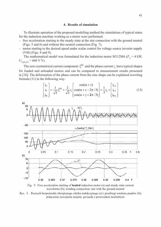
The zero symmetrical current component is( )0 and the phase current iU have typical shapes
for loaded and unloaded motors and can be compared to measurement results presented in [16]. The deformation of the phase current from the sine shape can be explained rewriting formula (11) in the following way:
iii
i iU
V
W
s s
= +
++ −+ +
13
23
2 30( )cos( )
cos( / )cos(
α γα γ πα γ 22 3
13
1
1
1π / )
= +
iiii
n
U
V
W
(13)
Fig. 5. Free acceleration starting of loaded induction motor (a) and steady state current waveforms (b); winding connection: star with the ground neutral
Rys. 5. Rozruch bezpośredni obciążonego silnika indukcyjnego (a) i przebiegi ustalone prądów (b); połączenie uzwojenia stojana: gwiazda z przewodem neutralnym

42
Fig. 6. Free acceleration starting of unloaded induction motor (a) and steady state current waveforms (b); winding connection: star with the ground neutral
Rys. 6. Rozruch bezpośredni nieobciążonego silnika indukcyjnego (a) i przebiegi ustalone prądów (b); połączenie uzwojenia stojana: gwiazda z przewodem neutralnym
Fig. 7. Free acceleration starting of loaded induction motor (a) and steady state voltage waveforms (b); winding connection: star without the ground neutral
Rys. 7. Rozruch bezpośredni obciążonego silnika indukcyjnego (a) i przebiegi ustalone napięć (b); połączenie uzwojenia stojana: gwiazda bez przewodu neutralnego
43
In equation (13) the modulus of stator current results from Fig. 2:
i i iii
iis sx sy
sx
s
sy
s= + = =2 2 ; cos ; sinγ γ (14)
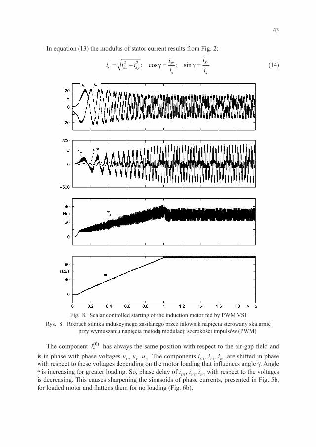
Fig. 8. Scalar controlled starting of the induction motor fed by PWM VSIRys. 8. Rozruch silnika indukcyjnego zasilanego przez falownik napięcia sterowany skalarnie
przy wymuszaniu napięcia metodą modulacji szerokości impulsów (PWM)
The component is( )0 has always the same position with respect to the air-gap field and
is in phase with phase voltages uU, uV, uW. The components iU1, iV1, iW1 are shifted in phase with respect to these voltages depending on the motor loading that influences angle g. Angle g is increasing for greater loading. So, phase delay of iU1, iV1, iW1 with respect to the voltages is decreasing. This causes sharpening the sinusoids of phase currents, presented in Fig. 5b, for loaded motor and flattens them for no loading (Fig. 6b).
44
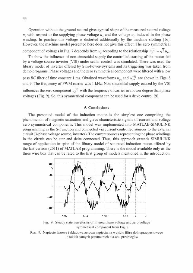
Operation without the ground neutral gives typical shape of the measured neutral voltage un with respect to the supplying phase voltage uA and the voltage uU induced in the phase winding. In practice this voltage is distorted additionally by the machine slotting [16]. However, the machine model presented here does not give this effect. The zero symmetrical
component of voltages in Fig. 7 descends from un according to the relationship u us n( ) .0 3=
To show the influence of non-sinusoidal supply the controlled starting of the motor fed by a voltage source inverter (VSI) under scalar control was simulated. There was used the library model of inverter offered by Sim-Power-Systems and its triggering was taken from demo programs. Phase voltages and the zero symmetrical component were filtered with a low
pass RC filter of time constant 1 ms. Obtained waveforms uUo and uso( )0 are shown in Figs. 8
and 9. The frequency of PWM carrier was 1 kHz. Non-sinusoidal supply caused by the VSI
influences the zero component us( )0 with the frequency of carrier in a lower degree than phase
voltages (Fig. 9). So, this symmetrical component can be used for a drive control [9].
5. Conclusions
The presented model of the induction motor is the simplest one comprising the phenomenon of magnetic saturation and gives characteristic signals of current and voltage zero symmetrical components. This model was implemented into MATLAB-SIMULINK programming as the S-Function and connected via current controlled sources to the external circuit (3-phase voltage source, inverter). The current sources representing the phase windings in the circuit can be star and delta connected. Thus, this approach extends SIMULINK range of application in spite of the library model of saturated induction motor offered by the last version (2011) of MATLAB programming. There is the model available only as the three wire box that can be rated to the first group of models mentioned in the introduction.
Fig. 9. Steady state waveforms of filtered phase voltage and zero voltage symmetrical component from Fig. 8
Rys. 9. Napięcie fazowe i składowa zerowa napięcia na wyjściu filtru dolnoprzepustowego o takich samych parametrach dla obu przebiegów
45
For example, sensitivity of MRAS methodology [28, 30] can be trained using the proposed here model. There can be studied the influence of magnetic core non-linearity on accuracy of determination of the rotor flux vector and, in result, the estimated motor speed.
The presented method for using S-Function can be applied to the mathematical models of other electrical machines, models of sophisticated electromechanical converters and other devices (not necessarily electrical). This is obvious that the model can be used for induction generator modelling. One SIMULINK program can contain a few S-Functions. The mechanical system can be modelled also as an S-Function or an electrical analogue eventually utilising Sim Mechanics library.
Time of computations is relatively short for sinusoidal supply of the motor and can acceptable even if MATLAB operates as an interpreter. However, for VSI supply computations become long and burdensome. Then, only a compiler gives relatively short times of computation comparable with SPICE family programs. An example for S-Function listing in MATLAB language has been given in Appendix.
R e f e r e n c e s
[1] Va s P., Generalised Analysis of Saturated AC Machines, Archiv fuer Elektrotech. 64, 1981, 57-62.
[2] K o v a c s K.P., Transient performance of an induction machine with variable saturation, Proc. ICEM’82, Part 1. Budapest (Hungary), 1982, 84-86.
[3] M e l k e b e e k J.A.A., Magnetising-field saturation and dynamic behaviour of induction machines (part 1, 2), IEE Proc., vol. 130, Pt.B, No 1, 1983, 1-17.
[4] Va s P., H a l l e n i u s K.E., B r o w n J.E., Cross-saturation of smooth air-gap electrical machines, IEEE Trans. on Energy Conv. EC-1,1986, 103-112.
[5] A n v a r i H.A., F a u c h e r J., T r e n n o y B., On the cross-coupling saturation effect and its computation by the finite difference solution, Proc. of ICEM’86, München 1986, 451-454.
[6] B o l d e a I., N a s a r S.A., Upon unitary treatment of magnetic saturation in orthogonal axis models of electrical machinery, Proc. of ICEM’86, München 1986, 172-175.
[7] J a c k A.G., Va s P., B r o w n J.E., A finite element study of the phenomenon of cross- -magnetization, Proc. of ICEM’86, München 1986, 462-465.
[8] W a r z e c h a A., Monoharmonic model of asynchronous machine with non-linear main magnetic circuit (in Polish),. Kwartalnik AGH, Elektrotechnika, t. 5, z. 4, Kraków 1986, 375-388.
[9] M o r e i r a J.C., L i p o T.A., Direct field orientation control using the third harmonic component of the stator voltage, Proc. of ICEM’90, Cambridge 1990, 1237-1242.
[10] S o b c z y k T.J., S o b c z y k K.M., On modelling of electromechanical energy converters with nonlinear magnetic circuit, Proc. of ICEM’90, Cambridge 1990, 1012-1015.
[11] D r o z d o w s k i P., Saturation and space harmonics effects in induction motors, Proc. of XII Symp. on Electromagnetic Phenomena in Nonlinear Circuits, Poznań 1991, 231-236.
[12] C o v i c G.A, B o y s J.T., Operating restrictions for third harmonic control of flux in induction machines, IEE Proc.-B, Vol. 139, No. 6 1992, 485-495.
[13] M o r e i r a J.C., L i p o T.A., Modelling of Saturated ac Machines Including Air Gap Flux Harmonic Components, IEEE Trans. on Ind. Appl., Vol. 28, No. 2, 1992, 343-349.
[14] S o b c z y k T.J., D r o z d o w s k i P., Inductances of electrical machine winding with a nonuniform air-gap, Archiv fuer Elektrotech. 76, 1993, 313-218.
46
[15] D r o z d o w s k i P., An equivalent permeance of the air-gap of induction motor in case of saturation, Seminar on Fundamentals of Electrotechnics and Ciruit Theory SPETO’94, 25-28.05.94 Gliwice 1994.
[16] D r o z d o w s k i P., Saturation and space harmonics in a star and delta connected squirrel-cage induction motor, Int. Conf. on Electr. Machines ICEM’94, vol. 3, Paris 1994, 93-98.
[17] S o b c z y k T.J., An energy – based approach to modelling the magnetic non-linearity in ac machines, ICEM’96, vol. 3, Vigo 1996, 68-73.
[18] D e m s M., Computer simulation of electromechanical waveforms in cage induction motors (in Polish), Sc. Bull. of Łodz Tech. Univ. no 754, Monograph 229, Łódź 1996.
[19] S o b c z y k T.J., Mathematical model of induction machines accounting for saturation due to the first and the third harmonics, ICEM’98, vol. 3, Istambul 1998, 1504-1509.
[20] S o b c z y k T.J., Energy-based approach to modelling magnetic non-linearity in AC machines. Part II – General equations of ac machines accounting for saturation due to the main MMF harmonic, Arch. of Electr. Eng., PWN, vol. 48, Bull. 3, Warszawa 1999, 279-294.
[21] D r o z d o w s k i P., Synthesis elements of polyphase windings for cage induction motors, Archives of Electrical Engineering, vol. XLVIII, No 1–2/1999, 63-68.
[22] R o n k o w s k i M., Induction machine simulation using PSPICE, Sc. Bull. 583, Elektryka 86, Gdańsk 2000, 179-190.
[23] K r z e m i ń s k i Z., Digital control of asynchronous machines, PAN, seria Postępy Napędu Elektrycznego, Wyd. Pol. Gdańskiej, Gdańsk 2000.
[24] S o b c z y k T.J., Methodical aspects of mathematical modeling of induction machines (in Polish), WNT, Warszawa 2004.
[25] K u d ł a J., Mathematical models of alternating current electrical machines taking into account magnetic saturation of cores (in Polish), Monografia, Zesz. Nauk. PŚ 1683, Wydawnictwo Politechniki Śląskiej, Gliwice 2005.
[26] D r o z d o w s k i P., K a p u s t a P., Modelling of induction machines with a non-linear magnetic core in SPICE (in Polish), Przegląd Elektrotechniczny nr 10/2007, 19-22.
[27] W a r z e c h a A., Multidimensional magnetising characteristics in circuital models of electrical machines (in Polish), Monografia 381, seria Inżynieria Elektryczna i Komputerowa, Wyd. PK, Kraków 2010.
[28] O r l o w s k a - K o w a l s k a T., D y b k o w s k i M., Stator-Current-Based MRAS Estima tor for a Wide Range Speed-Sensorless Induction-Motor Drive, IEEE Transactions on Industrial Electronics, vol. 57, no. 4, 2010, 1296-1308.
[29] D r o z d o w s k i P., D u d a A., MATLAB-SIMULINK modelling of induction machine incorporating magnetic saturation, Sc. Papers of the Institute of Electrical Machines Drives and Measurements of the Wrocław University of Technology No. 66, Studies and Research No. 32, vol. 2, Wrocław 2012, 38-44.
[30] K a m i ń s k i M., D y b k o w s k i M., Experimental tests of the MRASCC estimator with meutral speed adaptation mechanism, Sc. Papers of the Institute of Electrical Machines Drives and Measurements of the Wrocław University of Technology No. 66, Studies and Research No. 32, vol. 2, Wrocław 2012, 92-101.
Appendix
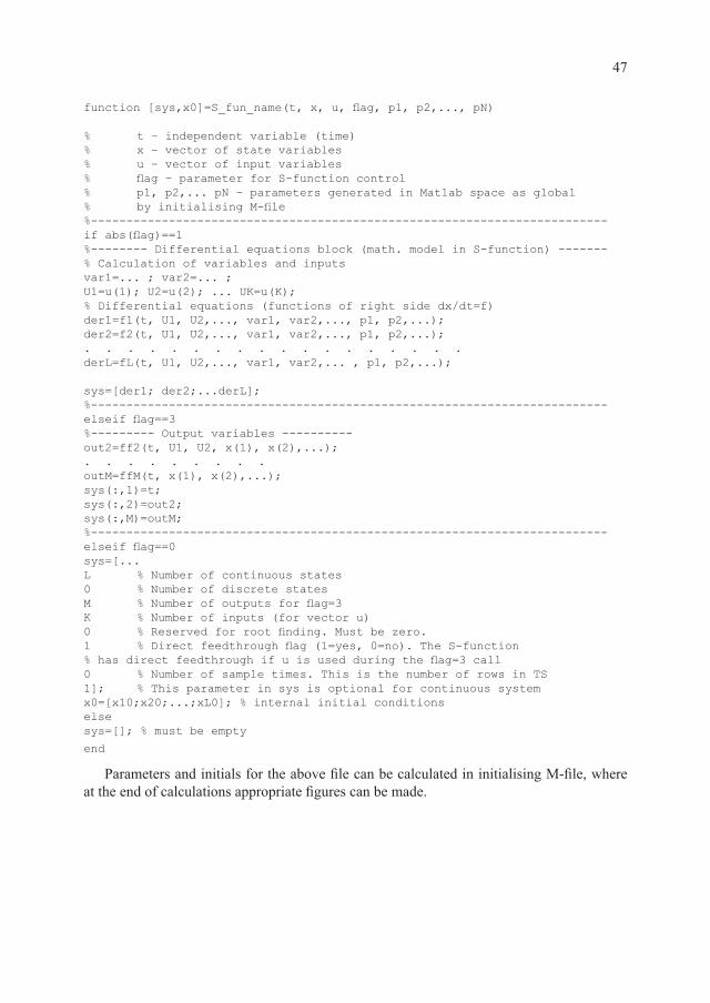
To create the S-function one can use the offered creator or write directly the program listing in MATLAB, C or FORTRAN. The simplest form written directly in MATLAB language has been shown below as a structure of file. To get more information about this structure one can enter sfundemos at the MATLAB command line.
47
function [sys,x0]=S_fun_name(t, x, u, flag, p1, p2,..., pN)
% t – independent variable (time)% x – vector of state variables% u – vector of input variables % flag – parameter for S-function control% p1, p2,... pN – parameters generated in Matlab space as global% by initialising M-file%-------------------------------------------------------------------------if abs(flag)==1%-------- Differential equations block (math. model in S-function) -------% Calculation of variables and inputsvar1=... ; var2=... ; U1=u(1); U2=u(2); ... UK=u(K);% Differential equations (functions of right side dx/dt=f)der1=f1(t, U1, U2,..., var1, var2,..., p1, p2,...); der2=f2(t, U1, U2,..., var1, var2,..., p1, p2,...);. . . . . . . . . . . . . . . . . .derL=fL(t, U1, U2,..., var1, var2,... , p1, p2,...);
sys=[der1; der2;...derL];%-------------------------------------------------------------------------elseif flag==3%--------- Output variables ----------out2=ff2(t, U1, U2, x(1), x(2),...);. . . . . . . . .outM=ffM(t, x(1), x(2),...);sys(:,1)=t;sys(:,2)=out2;sys(:,M)=outM;%-------------------------------------------------------------------------elseif flag==0sys=[...L % Number of continuous states0 % Number of discrete statesM % Number of outputs for flag=3K % Number of inputs (for vector u)0 % Reserved for root finding. Must be zero.1 % Direct feedthrough flag (1=yes, 0=no). The S-function% has direct feedthrough if u is used during the flag=3 call0 % Number of sample times. This is the number of rows in TS1]; % This parameter in sys is optional for continuous systemx0=[x10;x20;...;xL0]; % internal initial conditionselsesys=[]; % must be empty
end
Parameters and initials for the above file can be calculated in initialising M-file, where at the end of calculations appropriate figures can be made.