ASPECTS OF APPLICATION OF INDUSTRIAL ROBOTS IN ...imim.pl/files/archiwum/Vol1_2013/33.pdf ·...
7
A R C H I V E S O F M E T A L L U R G Y A N D M A T E R I A L S Volume 58 2013 Issue 1 DOI: 10.2478/v10172-012-0174-5 A. SMALCERZ * ASPECTS OF APPLICATION OF INDUSTRIAL ROBOTS IN METALLURGICAL PROCESSES ASPEKTY WYKORZYSTANIA ROBOTÓW PRZEMYSLOWYCH W PROCESACH METALURGICZNYCH Industrial robots are increasingly widely used in industrial metallurgical processes, their main aim being greater effective- ness of the process and higher precision of the tasks performed. The characteristic feature of numerous metallurgical processes, however, is the occurrence of strong electromagnetic fields. This paper presents the assessment of the accuracy of operation of an industrial robot in electromagnetic environment. The research encompassed the measurements of temperature of selected robot components and also the measurements of accuracy of the tasks performed. Additionally, some numerical simulations were carried out for determining the Joule losses produced in particular elements of the robot. The object of the research was an induction heater working with the industrial frequency. The numerical computations were performed by the code Flux 3D. Keywords: induction heating, industrial robot, simulation, electromagnetic field, temperature field Coraz szersze zastosowanie w procesach przemyslowych metalurgicznych znajdują roboty przemyslowe. Glównym celem stosowania robotów jest usprawnienie procesu oraz zwiększenie dokladności wykonywanych zadań. Jednak cechą charaktery- styczną procesów metalurgicznych jest występowanie pola elektromagnetycznego o znacznym natężeniu. W publikacji zostala przeprowadzona ocena poprawności dzialania robota przemyslowego w środowisku elektromagnetycznym. Badania obejmowaly pomiary temperatury elementów robota oraz dokladności wykonywania przez niego określonych zadań. Dodatkowo przepro- wadzono symulacje numeryczne, w których wyznaczono moc wydzielaną w poszczególnych elementach robota. Obliczenia numeryczne wykonano przy użyciu programu komputerowego Flux 3D. 1. Introduction One of the industrial branches where the devices used can be dangerous for employees as sources of electromagnetic field is electroheat treatment of materials. It is a sector of industry concerned with the transformations of electromag- netic field energy (generated by electric currents) into usable thermal energy together with the corresponding devices and their technical applications [1, 2, 3, 4]. One of the solutions eliminating the dangers of strong electromagnetic fields and improving the industrial process is using of different types of industrial robots and manipulators [5]. The most important features characterizing the performance of industrial robots follow [6]: • Repeatability – a measure of precision with which the ro- bot returns to the commanded point. It is a very important feature, especially in the situations where small tolerances are required. • Accuracy – the measure of error showing how closely the robot can reach a particular point in the working space. • Reliability – one of the most important features of the robot. It is the reliability that may in some cases stop the operation of the whole production plant. The drawback of this solution is a possible disturbance of the robot operation by a strong magnetic field on one hand and heating of the robot or manipulator components on the other hand [7]. So the main goal of the investigations is a determi- nation of Joule losses released in the metallic elements of the robot and consequent evaluation of its on induction heater. 2. Description of the studied object Obtaining a strong electromagnetic field in the laboratory conditions was a serious problem, and it was solved by using a two-layer cylindrical induction heater working with frequency f = 50 Hz (see Fig. 1). * SILESIAN UNIVERSITY OF TECHNOLOGY, DEPARTMENT OF MATERIAL SCIENCE AND METALLURGY, 40-019 KATOWICE, 8 KRASIŃSKIEGO STR., POLAND
Transcript of ASPECTS OF APPLICATION OF INDUSTRIAL ROBOTS IN ...imim.pl/files/archiwum/Vol1_2013/33.pdf ·...

A R C H I V E S O F M E T A L L U R G Y A N D M A T E R I A L S
Volume 58 2013 Issue 1
DOI: 10.2478/v10172-012-0174-5
A. SMALCERZ∗
ASPECTS OF APPLICATION OF INDUSTRIAL ROBOTSIN METALLURGICAL PROCESSES
ASPEKTY WYKORZYSTANIA ROBOTÓW PRZEMYSŁOWYCHW PROCESACH METALURGICZNYCH
Industrial robots are increasingly widely used in industrial metallurgical processes, their main aim being greater effective-ness of the process and higher precision of the tasks performed. The characteristic feature of numerous metallurgical processes,however, is the occurrence of strong electromagnetic fields. This paper presents the assessment of the accuracy of operation ofan industrial robot in electromagnetic environment. The research encompassed the measurements of temperature of selectedrobot components and also the measurements of accuracy of the tasks performed. Additionally, some numerical simulationswere carried out for determining the Joule losses produced in particular elements of the robot. The object of the research wasan induction heater working with the industrial frequency. The numerical computations were performed by the code Flux 3D.
Keywords: induction heating, industrial robot, simulation, electromagnetic field, temperature field
Coraz szersze zastosowanie w procesach przemysłowych metalurgicznych znajdują roboty przemysłowe. Głównym celemstosowania robotów jest usprawnienie procesu oraz zwiększenie dokładności wykonywanych zadań. Jednak cechą charaktery-styczną procesów metalurgicznych jest występowanie pola elektromagnetycznego o znacznym natężeniu. W publikacji zostałaprzeprowadzona ocena poprawności działania robota przemysłowego w środowisku elektromagnetycznym. Badania obejmowałypomiary temperatury elementów robota oraz dokładności wykonywania przez niego określonych zadań. Dodatkowo przepro-wadzono symulacje numeryczne, w których wyznaczono moc wydzielaną w poszczególnych elementach robota. Obliczenianumeryczne wykonano przy użyciu programu komputerowego Flux 3D.
1. Introduction
One of the industrial branches where the devices usedcan be dangerous for employees as sources of electromagneticfield is electroheat treatment of materials. It is a sector ofindustry concerned with the transformations of electromag-netic field energy (generated by electric currents) into usablethermal energy together with the corresponding devices andtheir technical applications [1, 2, 3, 4]. One of the solutionseliminating the dangers of strong electromagnetic fields andimproving the industrial process is using of different types ofindustrial robots and manipulators [5]. The most importantfeatures characterizing the performance of industrial robotsfollow [6]:• Repeatability – a measure of precision with which the ro-
bot returns to the commanded point. It is a very importantfeature, especially in the situations where small tolerancesare required.
• Accuracy – the measure of error showing how closely therobot can reach a particular point in the working space.
• Reliability – one of the most important features of therobot. It is the reliability that may in some cases stop theoperation of the whole production plant.The drawback of this solution is a possible disturbance of
the robot operation by a strong magnetic field on one hand andheating of the robot or manipulator components on the otherhand [7]. So the main goal of the investigations is a determi-nation of Joule losses released in the metallic elements of therobot and consequent evaluation of its on induction heater.
2. Description of the studied object
Obtaining a strong electromagnetic field in the laboratoryconditions was a serious problem, and it was solved by using atwo-layer cylindrical induction heater working with frequencyf = 50 Hz (see Fig. 1).
∗ SILESIAN UNIVERSITY OF TECHNOLOGY, DEPARTMENT OF MATERIAL SCIENCE AND METALLURGY, 40-019 KATOWICE, 8 KRASIŃSKIEGO STR., POLAND
204
Fig. 1. Induction heater a) device with shield, b) inductor withoutshield
Figures 2 and 3 and Table 1 present the basic dimensionsand power supply parameters of the device.
Fig. 2. Dimensions (in mm) of the inductor coil of the heater
Fig. 3. Symbols of dimensions of induction heater
TABLE 1Parameters and dimensions of induction heater
Parameter Unit Value
Frequency f , Hz 50
Supply current I , A 410
Active power Pn, kW 10Number of turns
of winding – 2×30 in two-layers
Dimensions mm
a b c d e f g
1100 1550 700 220 750 550 250
h1 h2 i j k l m n
900 500 50 90 90 300 190 90
Table 2 presents material properties of particular elementsof the heating system.
Fig. 4. Magnetization characteristic of the used material (steel 40HM)for different temperatures
A characteristic feature of the induction heater is the oc-currence of a strong electromagnetic field. The high intensityzone (that may be dangerous for people) covers the area withinabout 0.8 m from the heater, while the hazardous zone cov-ers the area within 1.8 m from the heater [9, 10]. The robotarm and its controller were placed in this zone, creating theenvironment for the described research.
The machine used for the experiment was a Kawasakiindustrial robot with a pneumatic gripper and additional ac-cessory (Fig. 5).
Fig. 5. Robot Kawasaki FS020NFD40 – max payload 20 kg

205
TABLE 2Material properties
parameter unit approximation quantity
work-piece (steel)
resistivity (Ωm) linear ρ = ρ0·(1+aT)ρ0 = 1.6 · 10−7Ωmα = 6.18 · 10−3K−1
relative magnetic permeability (-)scalar dependenceB (H) , see Fig. 4
Bs = 1.45TTc = 750C
thermal conductivity W/(m.K) linear λ = λ0·(1+aT)λ0 = 42.4 W/(m·K)a = –0.00033 (K)−1
volumetric heat capacity J/(m3K) special function [8]
E = 5.83·108 J/m3
Tc = 750Cσ = 55C
V0 = 3.7·106 J/(m3 C)Vi = 5·106 J/(m3 C)
τ = 500C
gripper fingers
resistivity (Ωm) – ρ0 = 1.7857 × 10⁻⁸Ωm
relative magnetic permeability (-)scalar dependenceB (H) , see Fig. 4
Bs = 1.45TTc = 750C
thermal conductivity W/(m.K) linear λ = λ0·(1+aT)λ0 = 42.4 W/(m·K)a = –0.00033 (K)−1
volumetric heat capacity J/(m3K) special function
E = 5.83·108 J/m3
Tc = 750Cσ = 55C
V0 = 3.7·106 J/(m3 C)Vi = 5·106 J/(m3 C)
τ = 500C
robot TCP, gripper
resistivity (Ωm) – ρ0 = 7.30·10−7Ωm
relative magnetic permeability (-) – 1
thermal conductivity, W/(m.K) linear λ = λ0·(1+aT)λ0 = 14.43 W/(m·K)a = 0.00108 (K)−1
volumetric heat capacity J/(m3K) linear ρc = ρc0·(1+aT)ρc0 = 3.84·108 J/(m3K)a = 0.000194 (K)−1
adapter
resistivity (Ωm)linear
ρ = ρ0·(1+aT)ρ0 = 0.265·10−7 Ωmα = 0.004 (K)−1
relative magnetic permeability (-) – 1
thermal conductivity, W/(m.K) – 235
volumetric heat capacity J/(m3K) – 2.53·106
Note: α is the temperature coefficient of resistance, Bs is the saturation magnetic flux density and Tc is the Curie temperature.
3. Numerical model
To solve the eddy-current problems in three-dimensionalsystems, the model TΦ−Φ/Φr was used. It combines the elec-tric vector potential T and scalar magnetic potential Φ for con-ductive areas (both magnetic and non-magnetic) with Φ for-mulated for non-conductive magnetic areas and reduced scalarmagnetic potential Φr for non-conductive and non-magneticareas [8, 11].
The electric vector potential is defined by the formula
J = curlT (1)
The scalar magnetic potential Φ is described by the depen-dence
H = T − grad Φ (2)
The above dependences lead to the equations which take thefollowing form for harmonic quantities:– for conductive areas
rot (1γ
rotT ) − grad(1γ
divT ) + j µω(T − gradΦ) = 0 (3)
div[µ(T − gradΦ)] = 0 (4)
wheregrad( 1
γdivT ) represents an expression referring to the bound-
ary condition divT = 0,– for non-conductive areas such as magnetic areas (e.g., grip-per fingers)
div [µ(−gradΦ)] = 0 (5)
206
while for the non-magnetic areas
div [µ0 (−gradΦr + H0)] = 0. (6)
The analysis of the temperature field was carried out by meansof the classic Fourier-Kirchhoff equation taking the followingform [8, 11]
∇ · (−λ∇T ) + ρc∂T∂t
= q (7)
where T is the temperature, λ denotes the thermal conductivityand q stands for the volumetric power density.
The complete mathematical model requires the initial andboundary conditions to be specified. The boundary conditiondescribed by (8) combines the radiation and convection modelsof heat dissipation
−λ∂T∂n
= α(T − T0c) + ε σ(T 4 − T 40r) (8)
where α is the convection coefficient, ε denotes the emissivityand σ stands for the Stephan-Boltzmann constant, T0c ambienttemperature, T0r temperature of radiation surface.
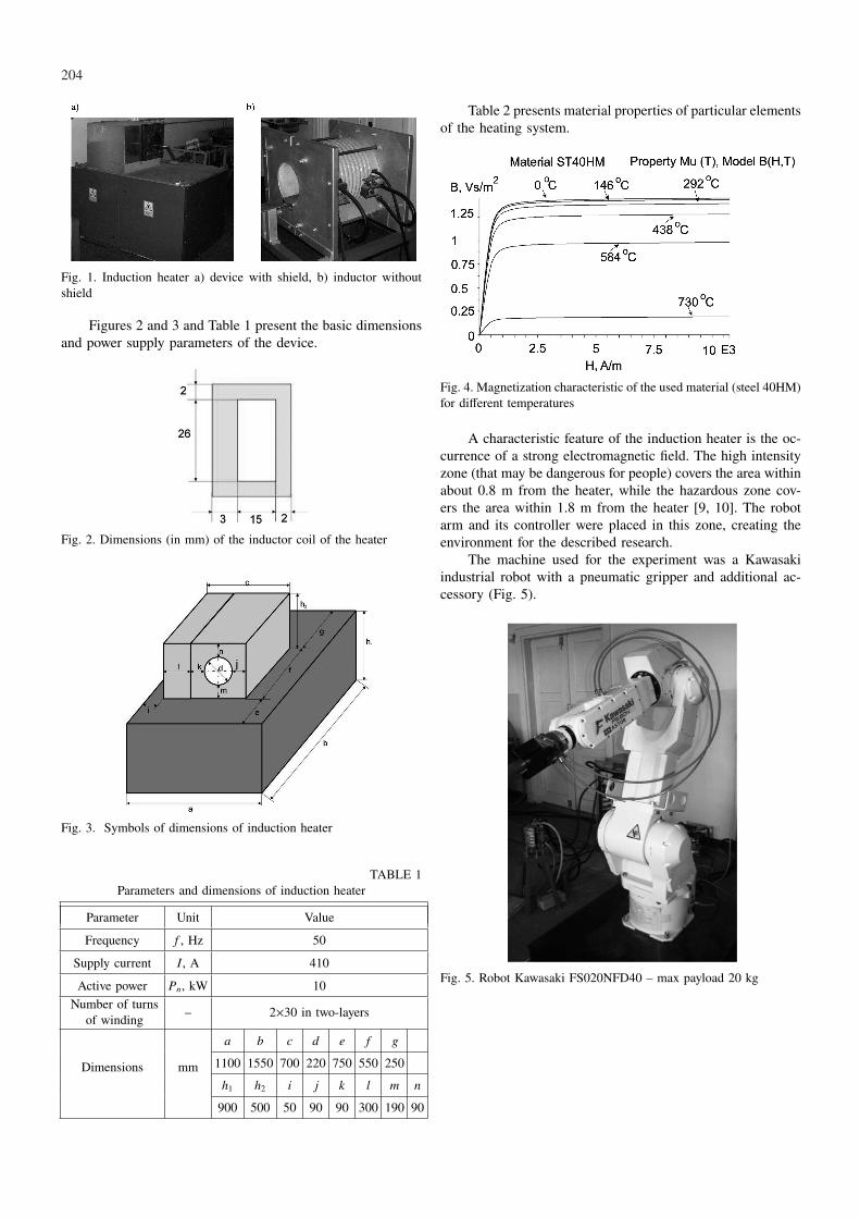
All numerical calculations, both for electromagnetic andtemperature fields, were performed by program Flux 3D.A simplified diagram of these calculations is presented inFig. 6.
Fig. 6. General calculation model of the coupled analysis of electro-magnetic and temperature fields
Figure 7 presents the arrangement used for the numericalmodeling. It consists of the induction heater – workpiece (red),inductor (cyan) – and the following elements of the robot –gripper fingers (blue), pneumatic gripper (light blue), adapter(violet) and TCP (yellow).
Fig. 7. Calculation model
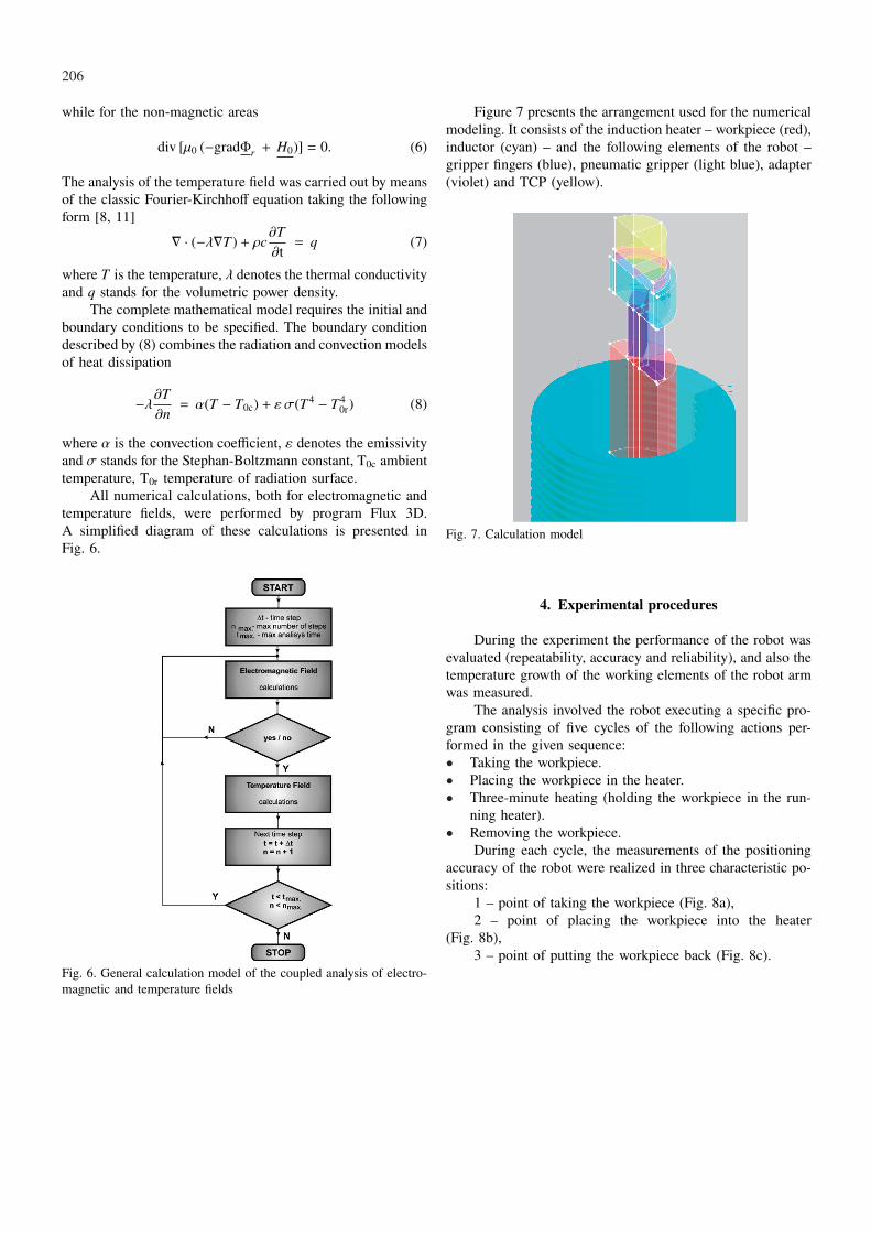
4. Experimental procedures
During the experiment the performance of the robot wasevaluated (repeatability, accuracy and reliability), and also thetemperature growth of the working elements of the robot armwas measured.
The analysis involved the robot executing a specific pro-gram consisting of five cycles of the following actions per-formed in the given sequence:• Taking the workpiece.• Placing the workpiece in the heater.• Three-minute heating (holding the workpiece in the run-
ning heater).• Removing the workpiece.
During each cycle, the measurements of the positioningaccuracy of the robot were realized in three characteristic po-sitions:
1 – point of taking the workpiece (Fig. 8a),2 – point of placing the workpiece into the heater
(Fig. 8b),3 – point of putting the workpiece back (Fig. 8c).

207
Fig. 8. Characteristic points of the robot operation, a) Point 1, b) Point 2, c) Point 3
5. Results and discussion
The aim of the experiment was to measure the tempera-ture of the industrial robot arm, and particularly the tempera-ture of the gripper (during the loading, heating and removingthe workpiece), and to evaluate the accuracy and repeatabilityof the actions performed. The two last measurements weretaken with a slide caliper. At this precision level no errorswere found. The robot controller did not display any unusualbehavior during the operation, either.
The temperature measurements were carried out with apyrometer while the general temperature distribution measuredby a thermocamera (Fig. 9) is presented in Fig. 10. This figureshows the robot gripper temperature distribution for selectedmoments of heating the workpiece. After the workpiece wastaken by the gripper (point 1, Fig. 8a), the robot, as pro-grammed, loaded the work-piece into the working heater. Theworkpiece remained in the inductor for three minutes and washeated (point 2 Fig. 8b). Picture 1 (in Fig. 10a) shows thetemperature distribution for the elements of the robot, partic-ularly for the gripper and the adapter, during the heating. Afterthis time the workpiece was removed from the heater by therobot (point 3, Fig. 8c). The temperature distributions in theelements of the robot and workpiece at this stage are shown inpicture 2 (Fig. 10b). Then, after 20 seconds the robot returnedto point 2 (Fig. 8a). The program performed 5 identical cycles.Picture 3 (Fig. 10c) presents the temperature distribution afterthe last, that is, the fifth cycle.
The only undesirable side-effect of the robot operationunder the influence of the electromagnetic field was that itselements heated. In the experiment described in the text thegripper fingers became the hottest, while the other parts werenot heated to such a level. The maximum temperature of the
gripper fingers was 70C; the adapter did not reach the tem-perature exceeding 45C, and the TCP was heated to about35C.
Fig. 9. Thermovision camera – Infrared Solution
The numerical simulations of the whole process of heat-ing the workpiece were conducted, too. During the calcula-tions the temperature of the elements and amount of the gen-erated Joule losses were controlled. Table 3 presents the resultsof the analysis.
TABLE 3Joule losses generated in the particular elements
Type ofworkpiece
P, W(workpiece)
P, W(fingers)
P, W(gripper)
P, W(adapter)
P, W(TCP)
magnetic steel 3275.5 15.7 181 139.4 8.2Non-magneticsteel 1930.2 8.8 131.8 80 5.1
Aluminum 2273.3 5.2 111.2 69.5 4.4

208
Fig. 10. Temperature distributions in the elements of the robot at the particular steps of the heating process: a) Picture 1. Temperature ofgripper and adapter – 150 second after the workpiece was placed into the heater (point 2), b) Picture 2. Temperature of gripper and adapter– after removing the workpiece (point 3), c) Picture 3. Temperature of workpiece and gripper – end of the fifth cycle (point 1)
In the created computer model, heat transfer by conduc-tion occurs between particular elements of the system. A sim-plification was made for the model that there is no physicalcontact between the robot gripper and the workpiece, while inreality, there is a point contact between them; however, takingthis into account in the model would significantly increasethe number of nodes and would lengthen the computationtime. Figure 11 presents the temperature distribution (after thefifth cycle) obtained by the numerical calculations and Fig. 12the distribution of temperature along the paths M and S (seeFig. 10 and 11).
Fig. 11. Temperature distribution – numerical simulation
Fig. 12. Temperature distribution along two paths
6. Conclusions
The experiment consisted in placing the elements of theindustrial robot into a strong magnetic field of the strengthexceeding 2000 A/m for four minutes in each cycle. The fol-lowing conclusions were reached:I The magnetic field did not affect the accuracy of the tasks
performed.

209
I The magnetic field did not influence the repeatability ofthe actions performed by the robot.
I During the experiment and research conducted for themains-frequency heater, the robot carried out all the tasksas programmed (it worked reliably). During further oper-ations no problems were encountered connected with theactions performed according to the program.
I The elements of the robot heated up under the influenceof the magnetic field. The maximum temperature of thegripper fingers reached 70C, although the exposure timewas very short (altogether about 20 minutes) and a rel-atively low power heater was used taking into accountindustrial conditions and the chosen frequency. Howev-er, it should be remembered that during the experimentthe fingers were inside the heater the entire time (sim-ilarly as the workpiece), which is not always necessary,(for example, when the robot will place the workpieceinside the heater and leave it there, and then remove itafter it has been heated). This will reduce the temperaturegrowth of the robot elements under the influence of themagnetic field and through thermal conduction (shortertime of contact with the work-piece). With each cycle thetemperature of the elements grew, while the temperaturegradients decreased significantly. In order to reduce thetemperature growth, some specific materials can be usedto cover the elements of the robot arm and insulate themfrom the heated elements.
I The temperature distributions obtained by measurementsare strongly consistent with those obtained by the numeri-cal simulations. Significant differences can only be noticedfor the gripper fingers, which results from the simplifica-tion made for the computer model (no contact betweenthe gripper and the work-piece).
Acknowledgements
This paper was supported by the Polish Ministry of Science andHigher Education under research project number N N508 479438.
REFERENCES
[1] A. B l a c h a, P. K o s c i e l n i a k, M. S i t a r z, J. S z u -b e r, J. Z a k, Pedot brushes electrochemically synthesized onthienyl-modified glassy carbon surfaces, Electrochimica Ac-ta 62, 441-446 (2012).
[2] J. Ł a b a j, G. S i w i e c, B. O l e k s i a k, Surface tension ofexpanded slag from steel manufacturing in electrical furnace,Metalurgija 50 (3), 209-211 (2011).
[3] Cz. S a j d a k, S. G o l a k, A. K u r e k, Electromagnetic stir-ring of liquid ingot core in the process of continuous castingof steel, Przeglad Elektrotechniczny 83, 67-70 (2007).
[4] J. B a r g l i k, Induction heating in technological processes– selected examples. Przeglad Elektrotechniczny 5 , 294-297(2010).
[5] J. B a r g l i k, A. K u r e k, R. P r z y ł u c k i, et al., Changeof electromagnetics field distribution around high and mediumfrequency heaters due to presence of industrial robots, ActaTechnica 57, 61-73 (2012).
[6] R. Z d a n o w i c z, Robotyzacja procesów technologicznych,Wydawnictwo Politechniki Śląskiej, Gliwice (2002).
[7] A. S m a l c e r z, R. P r z y l u c k i, Electromagnetic fieldanalysis of inductor – robot – work-piece system, Metalurgija52 (2), 223-226 (2013).
[8] FLUX3D 10.2 User’s guide. Cedrat, Grenoble (2009).[9] Directive 2004/40/EC of the European Parliament and of the
Council of on the minimum health and safety requirements re-garding the exposure of workers to the risks arising from phys-ical agents (electromagnetic fields) (18th individual Directivewithin the meaning of Article 16(1) of Directive 89/391/EEC).
[10] Rozporządzenie Ministra Ochrony Środowiska z dnia 30października 2003 r. w sprawie dopuszczalnych poziomów pólelektromagnetycznych w środowisku oraz sposobów sprawdza-nia dotrzymania tych poziomów. Dz. U. Nr 192, poz. 1883,(2003).
[11] M. N i k l e w i c z, A. S m a l c e r z, A. K u r e k, Estimationof system geometry and inductor frequency importance in in-duction hardening process of gears, Przeglad Elektrotechniczny84 (11), 219-224 (2008).
Received: 10 February 2012.