Arch. Min. Sci., Vol. 58 (2013), No 4, p. 1057–1070 · 1058 • zastosowanie pełnej...
14
Arch. Min. Sci., Vol. 58 (2013), No 4, p. 1057–1070 Electronic version (in color) of this paper is available: http://mining.archives.pl DOI 10.2478/amsc-2013-0073 ŁUKASZ BOŁOZ* UNIQUE PROJECT OF SINGLE-CUTTING HEAD LONGWALL SHEARER USED FOR THIN COAL SEAMS EXPLOITATION PROJEKT JEDNOORGANOWEGO KOMBAJNU ŚCIANOWEGO O SPECJALNEJ KONSTRUKCJI PRZEZNACZONEGO DO EKSPLOATACJI POKŁADÓW CIENKICH Problem of thin hard coal seams exploitation, including chosen data related with their resources in Po- land, has been discussed in the introduction of the present study. On the basis of actually operated machines the assumptions, which should be satisfied by the longwall shearer used for exploitation of thin hard coal seams, have been made. A project of such longwall shearer combined with band conveyor and mechanized longwall support, including description of the machine operation technology and analysis of possible day output achievement, have been presented. Keywords: thin hard coal seams, longwall shearer, analytical examinations of the machine load Polska dysponuje stosunkowo dużymi zasobami surowców energetycznych, a ciągle rosnące zapo- trzebowanie na energię skłania do ich racjonalnego wykorzystywania. Jedną z możliwości takiego racjo- nalnego gospodarowania zasobami naturalnymi jest eksploatacja węgla kamiennego z pokładów cienkich. W związku z wybieraniem coraz cieńszych pokładów węgla, zalegających bardzo głęboko, w trudnych warunkach górniczo-geologicznych napotyka się na duże problemy związane z uzyskaniem wymaganej wydajności wydobycia przy użyciu stosowanych aktualnie metod. Przyjmuje się, ze pokłady cienkie to takie o miąższości od 1.0 m do 1.5 m i właśnie ta niewielka wysokość wyrobiska ścianowego powoduje szereg ograniczeń związanych z efektywną eksploatacją węgla. Na podstawie dostępnych danych określono, że ilości węgla kamiennego w cienkich pokładach wynosi około 600 mln Mg. Znaczna część pokładów cienkich w ostatnich latach została przeklasyfikowana na nieprzemysłowe, co pozwala stwierdzić, że rzeczywista ilość węgla w pokładach cienkich jest znacznie większa. Na podstawie analizy wad i zalet jak i danych technicznych produkowanych obecnie maszyn, okreś- lono wytyczne i założenia do nowego rozwiązania maszyny urabiającej przeznaczonej do wydobywania węgla w ścianach niskich. Kombajn do eksploatacji cienkich pokładów powinien spełniać następujące wymagania (Bołoz, 2012): • praca w systemie ścianowym, • zastosowanie frezowania jako metody skrawania, • rozdzielenie procesu frezowania od procesu ładowania, * AGH UNIVERISTY OF SCIENCE AND TECHONOLOGY, FACULTY OF MECHANICAL ENGINEERING AND ROBOTICS, DEPARTMENT OF MINING, DRESSING AND TRANSPORT MACHINES, AL. A. MICKIEWICZA 30, 30-059 KRAKOW, POLAND, E-mail: [email protected]
Transcript of Arch. Min. Sci., Vol. 58 (2013), No 4, p. 1057–1070 · 1058 • zastosowanie pełnej...

Arch. Min. Sci., Vol. 58 (2013), No 4, p. 1057–1070Electronic version (in color) of this paper is available: http://mining.archives.pl
DOI 10.2478/amsc-2013-0073
ŁUKASZ BOŁOZ*
UNIQUE PROJECT OF SINGLE-CUTTING HEAD LONGWALL SHEARER USED FOR THIN COAL SEAMS EXPLOITATION
PROJEKT JEDNOORGANOWEGO KOMBAJNU ŚCIANOWEGO O SPECJALNEJ KONSTRUKCJI PRZEZNACZONEGO DO EKSPLOATACJI POKŁADÓW CIENKICH
Problem of thin hard coal seams exploitation, including chosen data related with their resources in Po-land, has been discussed in the introduction of the present study. On the basis of actually operated machines the assumptions, which should be satisfied by the longwall shearer used for exploitation of thin hard coal seams, have been made. A project of such longwall shearer combined with band conveyor and mechanized longwall support, including description of the machine operation technology and analysis of possible day output achievement, have been presented.
Keywords: thin hard coal seams, longwall shearer, analytical examinations of the machine load
Polska dysponuje stosunkowo dużymi zasobami surowców energetycznych, a ciągle rosnące zapo-trzebowanie na energię skłania do ich racjonalnego wykorzystywania. Jedną z możliwości takiego racjo-nalnego gospodarowania zasobami naturalnymi jest eksploatacja węgla kamiennego z pokładów cienkich. W związku z wybieraniem coraz cieńszych pokładów węgla, zalegających bardzo głęboko, w trudnych warunkach górniczo-geologicznych napotyka się na duże problemy związane z uzyskaniem wymaganej wydajności wydobycia przy użyciu stosowanych aktualnie metod. Przyjmuje się, ze pokłady cienkie to takie o miąższości od 1.0 m do 1.5 m i właśnie ta niewielka wysokość wyrobiska ścianowego powoduje szereg ograniczeń związanych z efektywną eksploatacją węgla. Na podstawie dostępnych danych określono, że ilości węgla kamiennego w cienkich pokładach wynosi około 600 mln Mg. Znaczna część pokładów cienkich w ostatnich latach została przeklasyfikowana na nieprzemysłowe, co pozwala stwierdzić, że rzeczywista ilość węgla w pokładach cienkich jest znacznie większa.
Na podstawie analizy wad i zalet jak i danych technicznych produkowanych obecnie maszyn, okreś-lono wytyczne i założenia do nowego rozwiązania maszyny urabiającej przeznaczonej do wydobywania węgla w ścianach niskich. Kombajn do eksploatacji cienkich pokładów powinien spełniać następujące wymagania (Bołoz, 2012):
• praca w systemie ścianowym,• zastosowanie frezowania jako metody skrawania,• rozdzielenie procesu frezowania od procesu ładowania,
* AGH UNIVERISTY OF SCIENCE AND TECHONOLOGY, FACULTY OF MECHANICAL ENGINEERING AND ROBOTICS, DEPARTMENT OF MINING, DRESSING AND TRANSPORT MACHINES, AL. A. MICKIEWICZA 30, 30-059 KRAKOW, POLAND, E-mail: [email protected]
1058
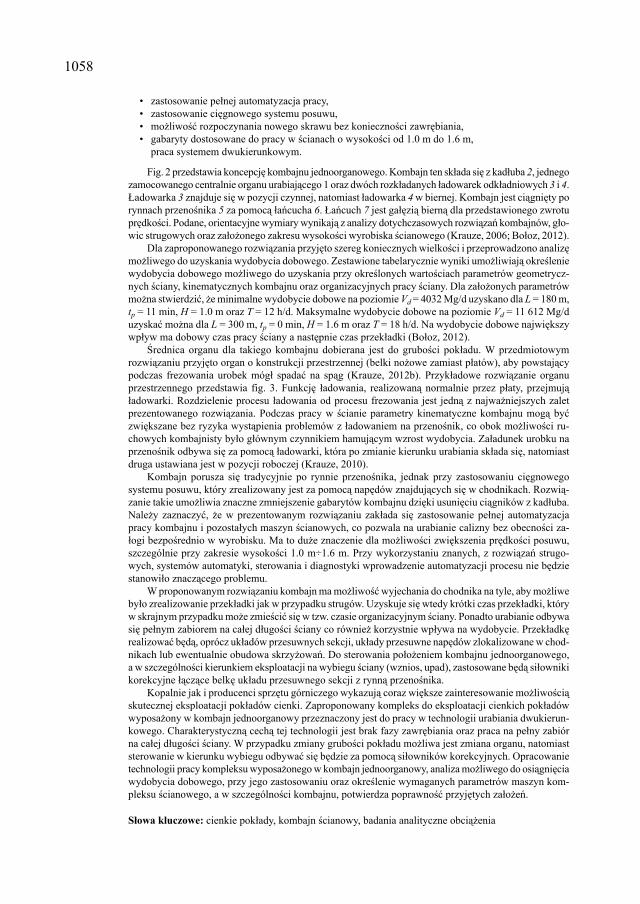
• zastosowanie pełnej automatyzacja pracy,• zastosowanie cięgnowego systemu posuwu,• możliwość rozpoczynania nowego skrawu bez konieczności zawrębiania,• gabaryty dostosowane do pracy w ścianach o wysokości od 1.0 m do 1.6 m, praca systemem dwukierunkowym.
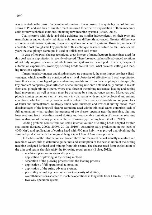
Fig. 2 przedstawia koncepcję kombajnu jednoorganowego. Kombajn ten składa się z kadłuba 2, jednego zamocowanego centralnie organu urabiającego 1 oraz dwóch rozkładanych ładowarek odkładniowych 3 i 4. Ładowarka 3 znajduje się w pozycji czynnej, natomiast ładowarka 4 w biernej. Kombajn jest ciągnięty po rynnach przenośnika 5 za pomocą łańcucha 6. Łańcuch 7 jest gałęzią bierną dla przedstawionego zwrotu prędkości. Podane, orientacyjne wymiary wynikają z analizy dotychczasowych rozwiązań kombajnów, gło-wic strugowych oraz założonego zakresu wysokości wyrobiska ścianowego (Krauze, 2006; Bołoz, 2012).
Dla zaproponowanego rozwiązania przyjęto szereg koniecznych wielkości i przeprowadzono analizę możliwego do uzyskania wydobycia dobowego. Zestawione tabelarycznie wyniki umożliwiają określenie wydobycia dobowego możliwego do uzyskania przy określonych wartościach parametrów geometrycz-nych ściany, kinematycznych kombajnu oraz organizacyjnych pracy ściany. Dla założonych parametrów można stwierdzić, że minimalne wydobycie dobowe na poziomie Vd = 4032 Mg/d uzyskano dla L = 180 m, tp = 11 min, H = 1.0 m oraz T = 12 h/d. Maksymalne wydobycie dobowe na poziomie Vd = 11 612 Mg/d uzyskać można dla L = 300 m, tp = 0 min, H = 1.6 m oraz T = 18 h/d. Na wydobycie dobowe największy wpływ ma dobowy czas pracy ściany a następnie czas przekładki (Bołoz, 2012).
Średnica organu dla takiego kombajnu dobierana jest do grubości pokładu. W przedmiotowym rozwiązaniu przyjęto organ o konstrukcji przestrzennej (belki nożowe zamiast płatów), aby powstający podczas frezowania urobek mógł spadać na spąg (Krauze, 2012b). Przykładowe rozwiązanie organu przestrzennego przedstawia fig. 3. Funkcję ładowania, realizowaną normalnie przez płaty, przejmują ładowarki. Rozdzielenie procesu ładowania od procesu frezowania jest jedną z najważniejszych zalet prezentowanego rozwiązania. Podczas pracy w ścianie parametry kinematyczne kombajnu mogą być zwiększane bez ryzyka wystąpienia problemów z ładowaniem na przenośnik, co obok możliwości ru-chowych kombajnisty było głównym czynnikiem hamującym wzrost wydobycia. Załadunek urobku na przenośnik odbywa się za pomocą ładowarki, która po zmianie kierunku urabiania składa się, natomiast druga ustawiana jest w pozycji roboczej (Krauze, 2010).
Kombajn porusza się tradycyjnie po rynnie przenośnika, jednak przy zastosowaniu cięgnowego systemu posuwu, który zrealizowany jest za pomocą napędów znajdujących się w chodnikach. Rozwią-zanie takie umożliwia znaczne zmniejszenie gabarytów kombajnu dzięki usunięciu ciągników z kadłuba. Należy zaznaczyć, że w prezentowanym rozwiązaniu zakłada się zastosowanie pełnej automatyzacja pracy kombajnu i pozostałych maszyn ścianowych, co pozwala na urabianie calizny bez obecności za-łogi bezpośrednio w wyrobisku. Ma to duże znaczenie dla możliwości zwiększenia prędkości posuwu, szczególnie przy zakresie wysokości 1.0 m÷1.6 m. Przy wykorzystaniu znanych, z rozwiązań strugo-wych, systemów automatyki, sterowania i diagnostyki wprowadzenie automatyzacji procesu nie będzie stanowiło znaczącego problemu.
W proponowanym rozwiązaniu kombajn ma możliwość wyjechania do chodnika na tyle, aby możliwe było zrealizowanie przekładki jak w przypadku strugów. Uzyskuje się wtedy krótki czas przekładki, który w skrajnym przypadku może zmieścić się w tzw. czasie organizacyjnym ściany. Ponadto urabianie odbywa się pełnym zabiorem na całej długości ściany co również korzystnie wpływa na wydobycie. Przekładkę realizować będą, oprócz układów przesuwnych sekcji, układy przesuwne napędów zlokalizowane w chod-nikach lub ewentualnie obudowa skrzyżowań. Do sterowania położeniem kombajnu jednoorganowego, a w szczególności kierunkiem eksploatacji na wybiegu ściany (wznios, upad), zastosowane będą siłowniki korekcyjne łączące belkę układu przesuwnego sekcji z rynną przenośnika.
Kopalnie jak i producenci sprzętu górniczego wykazują coraz większe zainteresowanie możliwością skutecznej eksploatacji pokładów cienki. Zaproponowany kompleks do eksploatacji cienkich pokładów wyposażony w kombajn jednoorganowy przeznaczony jest do pracy w technologii urabiania dwukierun-kowego. Charakterystyczną cechą tej technologii jest brak fazy zawrębiania oraz praca na pełny zabiór na całej długości ściany. W przypadku zmiany grubości pokładu możliwa jest zmiana organu, natomiast sterowanie w kierunku wybiegu odbywać się będzie za pomocą siłowników korekcyjnych. Opracowanie technologii pracy kompleksu wyposażonego w kombajn jednoorganowy, analiza możliwego do osiągnięcia wydobycia dobowego, przy jego zastosowaniu oraz określenie wymaganych parametrów maszyn kom-pleksu ścianowego, a w szczególności kombajnu, potwierdza poprawność przyjętych założeń.
Słowa kluczowe: cienkie pokłady, kombajn ścianowy, badania analityczne obciążenia

1059
1. Introduction
Poland has relatively big resources of power raw materials and continuously growing demand for the energy calls for their national use. One of possibilities of such rational natural resources management comprises exploitation of the hard coal from thin seams. Despite critical opinions related with use of the hard coal and liquid fuels, in order to satisfy high energy demand, none of the accessible energy source can be ignored.
As more and more thin coal seams are exploited, including those occurring at great depth in inconvenient mining and geological conditions, big problems related with obtaining required mining output with use of actually practiced methods are grown up. Actually, growing interest related with development of new thin seams exploitation technologies with use of longwall shearers and static shearers, is also observed. It is assumed that coal seams 1.0 to 1.5 m trick are classified as thin seams, and this small height of the longwall is related with a number of limita-tions influencing effective coal exploitation.
2. Exploitation of thin hard coal seams
Problem of the thin hard coal seams exploitation is a subject of interest both of users and producers of mechanized longwall machine systems. Hard coal exploitation is commenced from the most attractive resources with respect to mining profitability, i.e. exploitation of thick and medium sized coal seams, whereas thin and strongly dipped seams are left.
Participation of thin hard coal seams in total resources of Polish hard coal mines amounts for 16,5%, what is equivalent to 659 mln Mg of coal (Bajorski, 1999; Turek, 2005). According to other sources participation of thin seams in total operational resources of Polish hard coal mines amounts for 18%, what is equivalent to 550 mln Mg of the coal, whereas 420 mln Mg comprise developed seams and the rest of undeveloped ones (Sobczyk, 2008). For example, mine LW Bogdanka S.A. possesses 21,4% of coal occurring in seams 1.2 m÷1.5 m thick, what is equivalent to 76 mln Mg of coal (Stopa, 2008).
In actually working mines of the Upper Silesian Coal Basin, within thin seams, about 5 700 mln t of balance resources and over 1 700 mln ton of unbalanced industrial resources, have been documented, what is equivalent to 37% and 24% of total resources (Strzemiński, 2001). In the W KWK Zofiówka mine, coal seams 1.0 m÷1.5 m thick constitute even 38% what is equivalent to 113 mln Mg of coal (Tor, 2006). In the KWK Bolesław Śmiały mine, currently 51% of industrial resources comprise thin coal seams, in the KWK Krupiński mine 38%, in the KWK Budryk mine 37% and in the KWK Murcki mine 33% (Tytko, 2011). Great participation of thin coal seams in resource base of chosen countries of Europe and Asia should also be mentioned.
Despite total volume of hard coal, changes of classification systems of industrial and unbal-anced resources are also very important. Despite exploitation of medium and thick coal seams, participation of thin coal seams has decreased by half during the last decades. It results from resignation from the exploitation of already documented resources within coal seams of the thickness up to 1.5 m, as well as from classifying newly recognized thin seams as not industrial resources. This drop also results from hard coal mining restructurization programs.
Analysis of the data concerning chosen machines used for exploitation of thin hard coal seams, which are accessible on Polish and worldwide markets has also been made. This analysis
1060
was executed on the basis of accessible information. It was proved, that quite big part of thin coal seams In Poland and lack of suitable machines used for effective exploitation of these machines calls for new technical solutions, including new machine systems (Bołoz, 2012).
Coal shearers with blade and sidle guidance are similar independently on their type and manufacturer and obviously individual solutions are differently advanced. Greatest differences are seen in automation systems, diagnostic systems and control systems. However, in none of accessible coal ploughs the key problems of this technique has been solved so far. Since several years the coal plough technique is used in Polish hard coal mines.
In case of longwall shearer technique, great interest of manufacturers in machines used for thin coal seams exploitation is recently observed. Therefore new, technically advanced solutions of not only longwall shearers but whole machine systems are developed. However, despite of automation experiments, worm-type cutting heads are still used, what prevents cutting and load-ing functions separation.
If mentioned advantages and disadvantages are concerned, the most import are these disad-vantages, which actually are considered as critical obstacles of effective hard coal exploitation from thin seams, in such geological and mining conditions. In case of coal plough technique, the key problem comprises great influence of coal mining rate onto obtained daily output. It results from coal plough mining system, where total force of the mining resistance, loading and cutting head movement, as well as chain must be overcome by string advance system. Moreover, coal plough mining technique can by used only in coal seams with suitable geological and mining conditions, which are usually inconvenient in Poland. The convenient conditions comprise: lack of faults and intercalations, relatively small seam thickness and low coal cutting factor. Main disadvantages of the longwall shearer technique used within thin coal seams comprise: lack of full automation, what requires the presence of the shearer operator near the machine, big time loses resulting from the realization of slotting and considerable limitation of the output resulting from realization of loading process with use of worm-type cutting heads (Bołoz, 2012).
Loading problem results from too small internal volume of cutting heads adapted for thin coal seams (Krauze, 2009a, 2009b, 2010a, 2010b). Assuming daily production on the level of 4000 Mg/d and application of cutting head with 900 mm hub it was proved that obtaining the assumed production with the longwall height H = 1.0 m÷1.6 m is not possible.
On the basis of the information mentioned above and technical data of actually manufactured machines we are able to determine guidelines and assumption of the new solution of the cutting machine designed for hard coal mining from thin seams. The shearer used form exploitation of the thin coal seams should satisfy the following requirements (Bołoz, 2012):
• machine operation in longwall system, • application of plowing as the cutting method,• separation of the plowing process from the loading process,• application of full operational automation,• application of the string advance system,• possibility of making new cut without necessity of slotting,• overall dimensions adapted to machine operations in longwalls from 1.0 m to 1.6 m high,• two-way operation system.

1061
3. Longwall system equipped with a single cutting head shearer
Lonwall shearer system is defined as a set of machines used for the useful mineral exploita-tion. Longwall shearer system is composed of mechanized longwall support, longwall push-plate conveyor and longwall shearer.
Fig. 1 Scheme of mechanized longwall system with single cutting head is equipped with: 1, longwall push-plate conveyor 2, chain push-plate conveyor 4 and mechanized longwall sup-port 3. Location of push-plate conveyor 6 and drive units of the shearer advance 5 decides about location of the driver chain, which is located at the goafs side. Orient ation of shearer advance drives 5 (perpendicular or parallel) is arbitrary (Krauze, 2010a).
Fig. 1. Scheme of mechanized longwall system equipped with single cutting head (Krauze, 2010)
A concept of the single cutting head shearer is shown in Fig. 2. The shearer consists of the body 2, single cutting head centrally mounted 1 and two overhead loaders 3 and 4. The loader 3 is in active position, whereas the loader 4 in stand by position. The shearer is pulled on conveyor troughs 5 with use of the chain 6. Chain 7 is passive branch for given velocity. The proposed approximate dimensions result from the analysis of various shearer solutions, including cutting heads and assumed range of the longwall (Krauze, 2006; Bołoz, 2012).
Diameter of such shearer is matched to coal seam thickness, and the selected cutting head has no planes. Cutting as the mining method is recommended. In mining and geological conditions characteristic for Polish hard coal mines, coal seams are often hardly mined, they have numerous intercalations and variable thickness. In order to assure that the winning fall down on the floor, in the solution in question the cutting head of spatial construction was selected (cutters instead of planes) (Krauze, 2012b). Example of the spatial structure cutting head is shown in Fig. 3.
Loading function realized normally by planes is now realized by loaders. Separation of the loading process from the cutting process is one of the major advantages of the presented solu-tion. During longwall shearer operation its kinematic parameters can be increased without the risk related with problems of loading material onto conveyor, what was the major factor limit-ing the output increase. Loading of the winning onto conveyor is executed by the leader, which is assembled after direction change, whereas the second loader is set into operational position (Krauze, 2010b).
1062
Such manner of loading has not been used so far. It can be compared with application of worm-type cutting head leader, however the similarity is relatively small. Lack of knowledge on such solution in difficult conditions was the inspiration for development of the active loader design. Active leader can be placed within the shearer body and its mobile elements improve lo ading process (Krauze, 2012a).
Fig. 2. Concept of the single cutting head longwall shearer (Krauze, 2010a)
Fig. 3. Spatial cutting head used for salt beds mining in shaft SW-4
1063
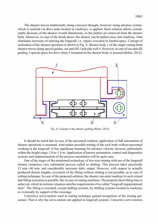
The shearer moves traditionally along conveyor thoughs, however string advance system, which is realized via drive units located in roadways, is applied. Such solution allows consid-erable decrease of the shearer overall dimensions, as the pullers are removed from the shearer body. Moreover, in case of the break down, the shearer can be pulled away into roadway, what eliminates necessity of entering the longwall, i.e. repairs executed in limited space. Concept of realization of the shearer operation is shown in Fig. 4. Shearer body 1 of the single cutting head shearer moves along special guides, cut-and-fill 3 and side wall 4. However, in case of cut-and-fill guiding 3 special space for drive chain 5 mounted on the shearer body, is assured (Bołoz, 2012).
Fig. 4. Concept of the shearer guiding (Bołoz, 2012)
It should be noted that in case of the presented solution, application of full automation of shearer operations is assumed, what makes possible mining of the rock body without personnel working in the longwall. It has significant meaning for advance velocity increase, particularly within the height range 1.0 m÷1.6 m. Application of known automation, control and diagnostics systems and implementation of the process automation will be quite easy.
One of the stages of the mentioned technology of two-way mining with use of the longwall shearer comprises very substantial process called as slotting. This process takes practically 15 min.÷60 min. and considerably increases daily output. However, with respect to actually produced shearer lengths, execution of the fitting without slotting is not possible, as in case of cutting technique. In case of the proposed solution, the shearer can enter roadway to such extend that fitting execution is possible, like in case of cutting machines. The properly short fitting time is achieved, which in extreme situation satisfies requirements of so called “longwall organizational time”. The fitting is executed, except shifting systems, by shifting systems located in roadways or eventually by support of the crossings.
Corrective servo-motors used in cutting technique gained recognition of the mining per-sonnel. That is why the servo-motors are applied in longwall systems. Corrective servo-motors

1064
connecting shifting system beam with conveyor though will be used for the control systems of the single cutting head shearer, including the exploitation direction (lift, dip).
When the shearer enters roadway, winning dumping into roadway can be expected, what happens also in case of cutting longwalls. The winning is removed from roadways with use of floor-loaders, however it reduces the longwall advance. Actually tested device, so called “Winning Self-loading System”, developed by companies „Sigma” S.A. and „Hajduk Group” Sp. z o. o., has a good reputation of the LW „Bogdanka” S.A mine personnel (fig. 5) (Masiakiewicz, 2011).
Fig. 5. Winning Self-loading System (Masiakiewicz, 2011)
In case of coal seam thickness change within the longwall, there is possibility of replac-ing the cutting head for bigger or smaller one, however in such case also change of the shearer base and height of the loader changes should be also taken under consideration. Taking under consideration proposed cutting range from 1.0 m to 1.6 m, four diameters of the cutting head f1000 mm, f1200 mm, f1400 mm and f1600 mm have been provided. Use of the cutting heads of the 800 mm web was assumed.
Real daily output is considered as the measure of the longwall system efficiency. On the basis of actual knowledge, organizational values of the longwall excavation have been assumed and the analysis of the daily output based on formulas known from literature has been made (Krauze, 2010c). In result suitable diagrams and tables have been made (Bołoz, 2012).
Example of the daily output diagram for 260 m long and 1.2 m high is shown in Fig. 6. The example analysis of the daily output is also marked on the diagram in question. Assuming that fitting will take 2 min and daily working time amounts 13 h/d, the daily output of about 6000 Mg/d is can be achieved. However, if the longwall daily working time is prolonged up to 15 h/d, fitting time can be increased even to 8 min and obtained daily output will be a little bigger.
The data gathered in tables are helpful in the daily output estimation, which can be obtained for given longwall geometrical parameters, shearer kinematic parameters and organizational parameters of the longwall. For the assumed parameters, daily output of Vd = 4032 Mg/d for L = 180 m, tp = 11 min, H = 1.0 m and T = 12 h/d, has been obtained. Daily working time within the longwall and fitting time have the greatest influence onto the daily output (Bołoz, 2012).

1065
The presented analysis of the daily output gives consideration only to longwall parameters (length, hight), shearer parameters (cutting, loading) and work organization parameters (daily working time, organizational time and fittings). Such aspects as the analysis of the shearer advance speed limitation related with conveyor winning receiving ability, as well as section re-setting time, have been neglected. Such attitude allowed selection of substantial parameters of the shearer independently on the mentioned conveyor and support. On the basis of critical parameters of the support and the conveyor for given longwall height, the following requirements have been established for whole thickness range of thin coal seams (Bołoz, 2012):
Push-plate conveyor:• width sr = 850 mm, • through profile wr = 200 mm,• chain plates speed vt = 1.5 m/s,• capacity Qt > 1400 Mg/d,
Mechanized longwall support:• section scale tob = 1.5 m,• time of the section re-setting tst < 7.5 s,• advance system stroke 850 mm,• operational range 1.0 m÷1.6 m,
Fig. 6. Daily output for the 260 m long and 1.2 m high longwall (Bołoz, 2012)

1066
The presented parameters of the longwall push-plate conveyor and mechanized longwall support allow application of actually produced machines. However it should be realized that there is need of special versions satisfying requirements of thin coal seams exploitation.
Determined geometrical and kinematic parameters of the single cutting head longwall shearer, longwall push-plate conveyor and roadway mechanized support allowed development of the preliminary project of the shearer in question and its model 3D in the program Autodesk Inventor. Taking into account direct shearer – conveyor – support cooperation, suitable models of these machines have been selected (Bołoz, 2012).
Longwall shearer system comprising single cutting head shearer 1, longwall push-plate con-veyor 2, mechanized section of the longwall support 3 and chain conveyor 4, is shown in Fig. 7. At both ends of the longwall conveyor its drive 5 and drive 6 of the shearer Fig. 7, are mounted.
The shearer body is designed in such manner that there is a enough space for the drive unit 2 ×120 kW of the cutting head (according to actual solutions review) together with planetary gear, safety devices, lubrication system and water cooling system. Besides the driving unit, hydraulic system powered from the cutting head driver, as well as automation, control and diagnostic sys-tems, are provided. Hydraulic system assures change of the loaders position and for is also used for the shearer shifting along the slippers. Size of individual elements was selected taking into account shape and size of actually used subassemblies of longwall shearers and coal plows. Length of the arm was determined on the basis of the winning stream volume during mining process.
Fig. 7. Longwall system equipped with single cutting head shearer (Bołoz, 2012)
Model of the shearer – view from the wall side – is shown in Fig. 8a. View from the exploi-tation side is shown in Fig. 8b. According to the assumptions, the longwall shearer is composed of the body 1, with drive unit 2 with spatial cutting head 3 mounted on the shaft end. Loaders are mounted on the shearer body via arms 4 and servo motors 5. Loader 6 is in active position, whereas leader 7 in passive position. The shearer body is equipped with two wall runners 8 and two cut and fill runners 9. Runners 8 are connected with the drive chain joint. From the cut and fill side the body is equipped with cable handler 9 with cables. Each loader is equipped with rollers 10 protecting against blocking on the floor undulations. The rollers are located along the floor and roof side edge of the loaders.

1067
Longwall shearer 1 on longwall conveyor 2 are shown in Fig. 9. Cables in cable handler 3 are conducted in conveyor gate 4. The shearer 1 is pulled by chain 5. Wall runner 6 of the shearer is shifted along the sidewall guide 7 of the conveyor, whereas cut and fill runner 8 is shifted along guide 9 of the conveyer. The longwall system is equipped with corrective servo motors 10.
Fig. 8. Sing le cutting head shearer, a) from the wall side b) from the old works side (Bołoz, 2012)
a)
b)

1068
Fig. 9. Singl e cutting head shearer moving on the conveyor (Bołoz, 2012)
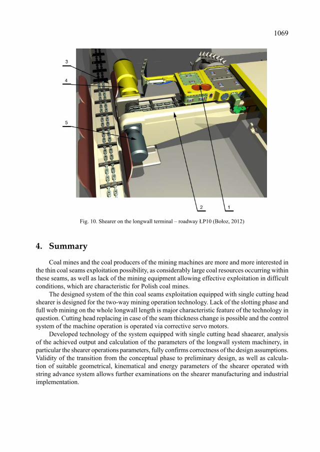
The shearer 1 at the longwall terminal prepared to new position is show in Fig. 10. Floor level of the roadway is lowered with respect to the lonwall level to such extend that conveyor drive 4 and shearer drive 5 can be covered with troughs. Face spill of the longwall conveyor 2 onto chain conveyor 3 has been applied in the presented solution.
1069
4. Summary
Coal mines and the coal producers of the mining machines are more and more interested in the thin coal seams exploitation possibility, as considerably large coal resources occurring within these seams, as well as lack of the mining equipment allowing effective exploitation in difficult conditions, which are characteristic for Polish coal mines.
The designed system of the thin coal seams exploitation equipped with single cutting head shearer is designed for the two-way mining operation technology. Lack of the slotting phase and full web mining on the whole longwall length is major characteristic feature of the technology in question. Cutting head replacing in case of the seam thickness change is possible and the control system of the machine operation is operated via corrective servo motors.
Developed technology of the system equipped with single cutting head shaearer, analysis of the achieved output and calculation of the parameters of the longwall system machinery, in particular the shearer operations parameters, fully confirms correctness of the design assumptions. Validity of the transition from the conceptual phase to preliminary design, as well as calcula-tion of suitable geometrical, kinematical and energy parameters of the shearer operated with string advance system allows further examinations on the shearer manufacturing and industrial implementation.
Fig. 10. Shear er on the longwall terminal – roadway ŁP10 (Bołoz, 2012)

1070
References
Bajorski J., Bula M., Kania J., 1999. Zespoły maszyn i urządzeń do wysokiej koncentracji wydobycia węgla kamiennego ze ścian w pokładach cienkich. Szczyrk, Materiały szkoły eksploatacji podziemnej.
Bołoz Ł., 2012. Ocena obciążenia jednoorganowego kombajnu ścianowego na podstawie badań analitycznych. Praca Doktorska, AGH w Krakowie, Kraków.
Krauze K., 2000. An analytical assessment of loading process for cutting elements of longwall cutter-loader. Arch. Min. Sci., Vol. 45, No. 3.
Krauze K., 2002. Ocena możliwości technicznych efektywnego wybierania cienkich pokładów. Kraków, Materiały Szkoły Eksploatacji Podziemnej.
Krauze K., 2006. Określenie warunków dla stosowania statycznych strugów węglowych. Mechanizacja i Automatyzacja Górnictwa, Nr 3.
Krauze K., 2010c. Model-based estimation of daily production output for various technologies of the longwall operation. Arch. Min. Sci., Vol. 55, No. 4.
Krauze K., Bołoz Ł., 2009a. Eksploatacja cienkich pokładów węgla kamiennego. [w:] Wybrane problemy eksploatacji węgla i skał zwięzłych, Red. Krauze K., Reś J., Kraków, Katedra Maszyn Górniczych, Przeróbczych i Transportowych.
Krauze K., Bołoz Ł., 2009b. Koncepcja wybierania cienkich pokładów węgla kamiennego. Transport Przemysłowy i Maszyny Robocze, Nr 3.
Krauze K., Bołoz Ł., 2010a. Exploitation of hard coal seams. Selected problems of coal and cohesive rocks exploitation. A collective work under the direction of Antoni Kalukiewicz, Janusz Reś. Cracow, Department of Mining, Dressing and Transport Machines.
Krauze K., Bołoz Ł., 2010b. Model jednoorganowego frezującego kombajnu ścianowego. Napędy i Sterownie, Nr 12.Krauze K., Bołoz Ł, 2012a. Projekt wynalazczy. Polska. nr P. Głowica ładująca kombajnu ścianowegoKrauze K., Wydro T., Bołoz Ł., 2012b. Frezujący organ urabiający nowej generacji do urabiania soli kamiennej w wa-
runkach drążenia wyrobiska szybowego. Kraków, Materiały Szkoły Eksploatacji Podziemnej.Masiakiewicz M., Szyszka A., 2011. Praktyczne elementy optymalizacji systemów mechanizacji ścian strugowych
w warunkach LW „Bogdanka“ S.A. [w:] Nowe spojrzenie na technikę i technologię eksploatacji cienkich pokładów węgla kamiennego. Red. A. Dyczko i in., Kraków, Fundacja dla AGH.
Sobczyk J., 2008. Zasoby węgla kamiennego w Polsce a możliwość zaspokojenia potrzeb energetyki. Polityka energe-tyczna, Nr 1.
Stopa Z., 2008. Perspektywy eksploatacji cienkich pokładów węgla kamiennego w LW „Bogdanka” S.A. Szczyrk. Ma-teriały Szkoły Eksploatacji Podziemnej.
Strzemiński J., 2001. Strugi węglowe, rozwój, stan aktualny, perspektywy cz. 1. Mechanizacja i Automatyzacja Górnic-twa, Nr 3.
Tor A., 2006. Nowoczesna technika strugowa jako sposób na zwiększenie racjonalnego wykorzystania złóż węgla w JSW S.A. KWK „Zofiówka”. Szczyrk, Materiały Szkoły Eksploatacji Podziemnej.
Turek M., 2005. Nie pozostawiajmy pokładów cienkich. Przegląd Górniczy, Nr 10.Tytko S., Walczak Z., Dziura J., Skrzypiec A., 2011. Kompleks ściany do wybierania cienkich pokładów. [w:] Nowoczesne
metody eksploatacji węgla o skał zwięzłych, Kraków, Katedra Maszyn Górniczych, Przeróbczych i Transportowych.
Received: 25 April 2013