AC-115 Hardware IM
58
Hardware Installation and User’s Guide ROSSLARE AC-115 0 8 5 2 1 4 6 3 9 7 # MODE DOOR 10/01
-
Upload
honorio-vera-rojas -
Category
Documents
-
view
216 -
download
0
Transcript of AC-115 Hardware IM
8/6/2019 AC-115 Hardware IM
http://slidepdf.com/reader/full/ac-115-hardware-im 1/58
Hardware Installation and User’s Guide
ROSSLARE
AC-115
0
8
5
21
4 6
3
97
#
MODE DOOR
10/01
8/6/2019 AC-115 Hardware IM
http://slidepdf.com/reader/full/ac-115-hardware-im 2/58
Hardware Installationand User’s Guide for the AC-115
Access Control System
ROSSLARE
0
8
5
21
4 6
3
97
#
MODE DOOR
8/6/2019 AC-115 Hardware IM
http://slidepdf.com/reader/full/ac-115-hardware-im 3/58
Information in this document, including URL and other Internet Web site references, is subject to change without notice. Unless otherwise noted, the
example companies, organizations, products, people and events depicted herein are fictitious and no association with any real company, organization,
product,personor eventis intended or should be inferred.
© Copyright2000 Rosslare.
Software License Agreement.
Limitation of Liability.
U.S.Government RestrictedRights.
All rights reserved.
Rosslare, the Rosslare logo, and the Rosslare products referred to herein are either the trademarks or registered to the trademarks of Rosslare, All other
trademarksare the propertyof theirrespectiveowners.
ROSSLARE IS WILLING TO LICENSE THE ENCLOSED SOFTWARE ONLY ON THE CONDITION THAT YOUACCEPT ALL OF THE TERMS
CONTAINED INTHISLICENCEAGREEMENT. This is a legal agreement between you(either theindividual orthe end-user oran entity) andRosslare.
By opening this software package, you are agreeing to be bound by the terms and conditions of this Agreement. If you do not agree to the terms of this
Agreement, promptly return thesoftware package andotheritems that are part of this product in their original package with your payment receipt to your
pointof purchase fora full refund. Grant of License. Rosslare andits suppliersgrantyou a nonexclusivelicense to useone copy ofthe enclosed software
program ("Software")on onecomputer withthe Rosslare product youhavepurchased. Nootherrights aregranted. Thesoftwareis in useif it is loadedon
the computer's permanent or temporary memory. For backup purposes only you may make one copy of the Software. You must include on the backup
copy all copyright and other notices included on the Software as supplied by Rosslare. Installation on a Network server for the sole purpose of your
internal distribution of the Software is permitted only if you have purchased an individual software package for each networked computer to which the
software is distributed. Restrictions. Rosslare and its suppliers retainownershipof the Software. You may not decompile, disassemble,reverse engineer,or modifythe Software in anyway. You maynot transmit thesoftwareover a network (except as expresslypermittedabove),by telephone,or electrically
using anymeans. You maynot transfer theSoftwareexcept upon a permanenttransferof theenclosedRosslare product provided that all software updates
areincludedin thetransfer, youdo notretain a copy ofthe Software,andthe transfereeagrees tobe boundby thetermsandconditionsof this license. Upon
any violation of any of the provisions of this Agreement, rights to use the Software shall automatically terminate a nd the Software must be returned to
Rosslare or all copies of the Software destroyed. Limited Product Warranty. Rosslare warrants that any hardware products accompanying this
documentation shall be free from significant defects in material and workmanship for a period of one year from the date of purchase. Rosslare also
warrants thatthe Software accompanying thisdocumentation willperformsubstantially in accordancewith the documentation fora period of 90 daysfrom
purchase. Rosslare's hardware and software warranty is nontransferable and is limited to the original purchaser. Product Remedies. Rosslare's entire
liability and the licensees exclusive remedy for any breech of warranty, shall be, at Rosslare's sole option, either a) return the price paid or b) repair or
replacement of hardware or software, provided that the hardware is returned to the point of purchase, with a copy of the sales receipt. Any replacement
hardware and software will be warranted for the remainder of the original warrantee period or 30 days for the hardware and 30 days for the software,
whicheveris longer. Theremedies are voidif failure of the softwareor hardwarehas resulted fromabuse, accident or misapplication.
THE WARRANTIES SET FORTH IN THISAGREEMENT REPLACE ALL OTHER WARRANTIES. ROSSLARE EXPRESSLY DISCLAIMSALL
OTHER WARRANTIES, INCLUDING BUT NOT LIMITED TO, THE IMPLIEDWARRANTIES OF MERCHANTABILITYAND FITNESS FOR A
PARTICULAR PURPOSEAND NON-INFRINGEMENT OFTHIRD PARTYRIGHTS WITHRESPECTTO THEDOCUMENTATION, SOFTWARE,
AND HARDWARE. NO ROSSLARE DEALER, AGENT, OR EMPLOYEE ISAUTHORISED TO MAKEANY MODIFICATION, EXTENSION,OR
ADDITION TOTHISWARRANTY. IN NO EVENTWILLROSSLARE OR IT”S SUPPLIERSBE LIABLE FORANYCOSTSOF PROCUREMENT
OF SUBSTITUTE PRODUCTS OR SERVICES, LOST PROFITS, LOSS OF INFORMATION OR DATA, ORANY OTHER SPECIAL DIRECT OR
INDIRECT, CONSEQUENTIAL, OR INCIDENTAL DAMAGES ARISING IN ANYWAY OUT OF THE SALE, OF, USE OF, OR INABILITY TO
USE ANY ROSSLARE PRODUCT OR SERVICE, EVEN IF ROSSLARE HAS BEEN ADVISED OFTHE POSSIBILITY OF SUCH DAMAGES. IN
NO CASESHALLROSSLARE’SLIABILITYEXCEED THEACTUALMONEYPAID FORTHE PRODUCTSATISSUE.Because somejurisdictions
do notallow theimplementation of limitedwarranties or liability forincidental,consequential,special, or indirect damages, theabovelimitationmay not
alwaysapply. Theabove limitations will notapply incase ofpersonalinjurywhereandto theextent that applicablelaw requiressuchliability.
Thesoftwareis provided to theU.S.Government only with restrictedrights andlimited rightsof use, duplication ordisclosure bythe U.S. Government is
subject to restrictions set forth in 48 C.F.R 2.101 (Oct 1995) consisting of "Commercial Computer Software" and "Commercial Computer Software
Documentation" as such terms areused in 48C.F.R. 12.212(September1995), andin FAR Sections 52-227-14and 52-227-19or DFARSSection 52.227-
7013 (C) (ii), or their successors, as applicable. Consistent with 48. C.F.R. 12.212 and 48 C.F.R. 227.7202-1 through 227.7204-1 (June 1995), or anysuccessor regulations, this software is providedto the termsand conditionsherein. Contractor/Manufacturer Rosslare EnterprisesLtd. 12WangTai Road,
HongKong.
8/6/2019 AC-115 Hardware IM
http://slidepdf.com/reader/full/ac-115-hardware-im 4/58
Table of Contents
Introduction 4Key Features 5Technical Specifications 6
Installation
Features and Concepts
Programming Instructions
Appendix
Technical Support
8
13
22
57
Mounting the Controller 9Power Wiring 10Typical Lock and Option Wiring 10Reader Wiring 11Connecting a controller to a PC 11Connecting a system to a PC 12
Code Assignment (Lock Strike & Auxiliary) 14Modes of Operation 15Changing the Modes of Operation 17Events and Event Actions 19
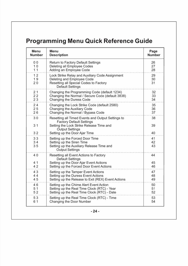
Programming Manual 23Programming Quick Reference Guide 24
Appendix 1 : Replacing a lost Programming Code 55
Appendix 2 : Replacing a lost Normal / Secure Code 56
8/6/2019 AC-115 Hardware IM
http://slidepdf.com/reader/full/ac-115-hardware-im 5/58
Introduction
The AC-115 is an advanced single door
controller, of which up to 8 units can beconnected together along with a PC toform an 8-door, PC programmablenetwork.
The AC-115 has been designed to behighly flexible, allowing it to be usedin multiple applications. The controller is feature rich, and provides the user valuable control over the door(s) it isattached to.
When using the AC-115 as a standalonecontroller, it can be programmed usingits own built in programming keypad or by using the AC-115 PC Software.
When using the AC-115 in a multi-controller network, the network of controllers can only be programmedusing the AC-115 PC software.
In this manual you will learn how to
easily install and program the AC-115using the controller’s built in programming keypad.
Programming the AC-115 with a PC is
even easier and unlocks features thataren’t accessible from the controller’s programming keypad. Programmingthe AC-115 with a PC is covered in the provided Software Installation andUser’s Guide.
It is recommended that the HardwareManual be read first before theSoftware Manual as key concepts areintroduced in the Hardware Manual
that are not covered in the SoftwareManual.
Topics in this Chapter
!
!
Key Features
Technical Specifications
1
- 4 -
8/6/2019 AC-115 Hardware IM
http://slidepdf.com/reader/full/ac-115-hardware-im 6/58
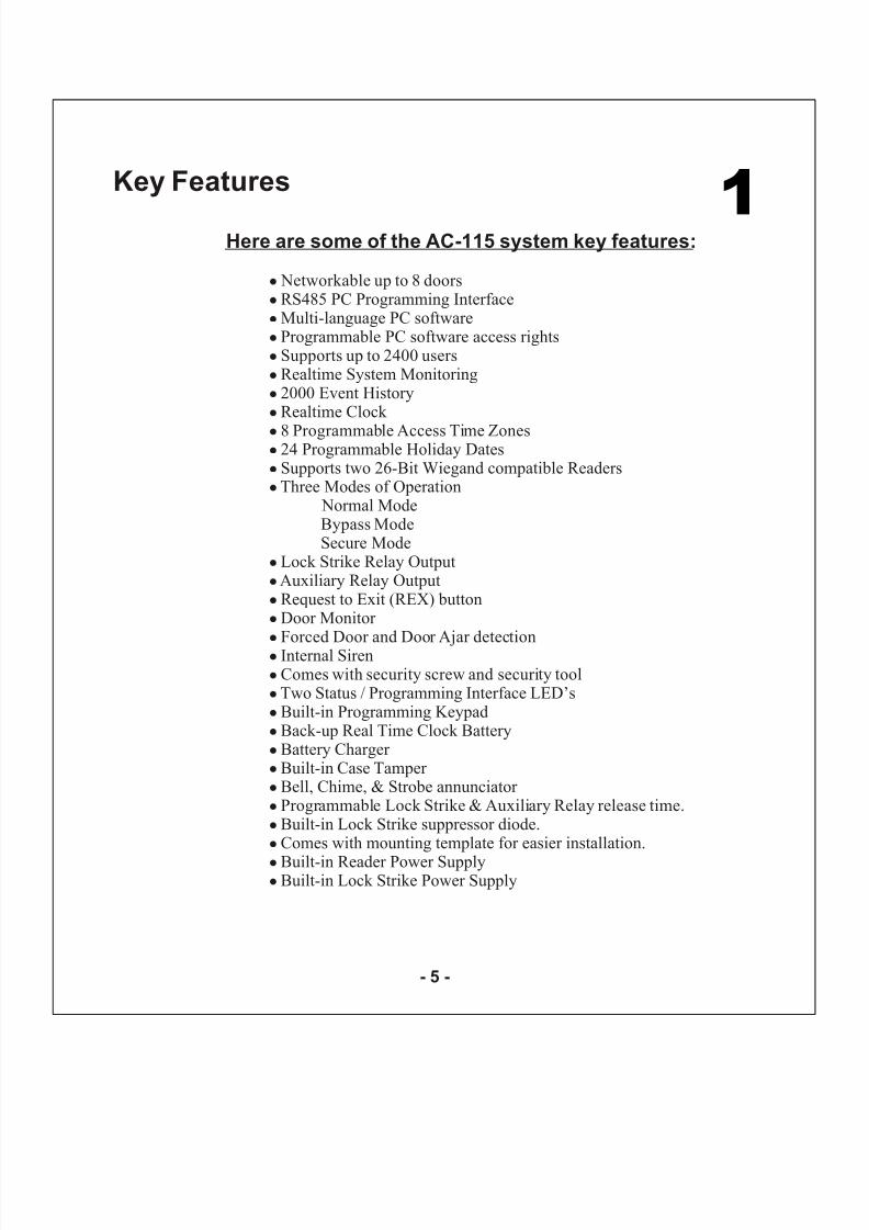
Here are some of the AC-115 system key features:
!
!
!
!
!
!
!
!
!
!
!
!
!
!
!
!
!
!
!
!
!
!
!
!
!
!
!
!
!
!
Networkable up to 8 doorsRS485 PC Programming InterfaceMulti-language PC softwareProgrammable PC software access rightsSupports up to 2400 usersRealtime System Monitoring2000 Event HistoryRealtime Clock
8 Programmable Access Time Zones24 Programmable Holiday DatesSupports two 26-Bit Wiegand compatible ReadersThree Modes of Operation
Normal ModeBypass ModeSecure Mode
Lock Strike Relay OutputAuxiliary Relay OutputRequest to Exit (REX) buttonDoor Monitor Forced Door and Door Ajar detectionInternal SirenComes with security screw and security toolTwo Status / Programming Interface LED’sBuilt-in Programming KeypadBack-up Real Time Clock BatteryBattery Charger Built-in Case Tamper Bell, Chime, & Strobe annunciator Programmable Lock Strike & Auxiliary Relay release time.Built-in Lock Strike suppressor diode.Comes with mounting template for easier installation.
Built-in Reader Power SupplyBuilt-in Lock Strike Power Supply
1Key Features
- 5 -
8/6/2019 AC-115 Hardware IM
http://slidepdf.com/reader/full/ac-115-hardware-im 7/58

8/6/2019 AC-115 Hardware IM
http://slidepdf.com/reader/full/ac-115-hardware-im 8/58
Two Tri-Colored LEDs
Built in Sounder (Bell, Chime & Siren)Piezoelectric Buzzer
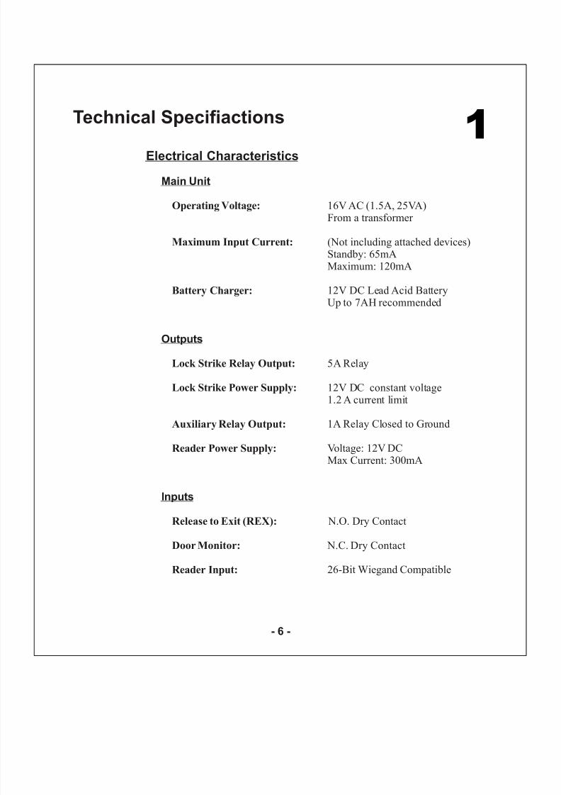
-25
5.3” (134mm) L x 3.4” (85mm) W x 1.2” (30mm) D(Fits US Gang Box)
Indicators & Annunciators
Visual:
Operating Temperature:
Dimensions:
Environmental Characteristics
Mechanical Characteristics
F to 145 F (-31 C to 63 C)
0 to 95% (Non-Condensing)
0.5 lbs (220g)
Audio:
Operating Humidity:
Weight:
° ° ° °
1
- 7 -
8/6/2019 AC-115 Hardware IM
http://slidepdf.com/reader/full/ac-115-hardware-im 9/58
Installation
The AC-115 has been designed for easy
installation. Only a few steps arerequired to install the controller.
In this chapter you will learn how tomount the controller in your desiredlocation.
You will learn how to wire thecontroller to its power source whichincludes attaching the controller to arechargeable Lead Acid battery.
Wiring diagrams are also provided for attaching the controller to the REX button, Door Monitor switch, AuxiliaryOutput, and External 26-Bit WiegandCompatible readers.
Also covered in this chapter is how towire the AC-115 to a PC as a singleunit and for use in a system of networked AC-115’s.
Topics in this Chapter
!
!
!
!
!
!
Mounting the Controller
Power Wiring
Typical Lock and Option Wiring
Reader Wiring
Connecting a controller to a PC
Connecting a system to a PC
2
- 8 -
8/6/2019 AC-115 Hardware IM
http://slidepdf.com/reader/full/ac-115-hardware-im 10/58
8/6/2019 AC-115 Hardware IM
http://slidepdf.com/reader/full/ac-115-hardware-im 11/58
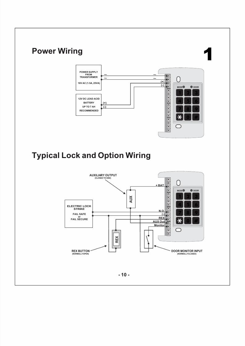
1Power Wiring
0
8
5
21
4 6
3
97
#
MODE DOOR
POWER SUPPLYFROM
TRANSFORMER
16V AC (1.5A, 25VA)
(+)
(-)
12V DC LEAD ACID
BATTERY
UP TO 7 AH
RECOMMENDED
(+)
(-)
~
~~
~
Typical Lock and Option Wiring
0
8
5
21
4 6
3
97
#
MODE DOOR
R
E X
ELECTRIC LOCK
STRIKE
FAIL SAFE
or
FAIL SECURE
DOOR MONITOR INPUT(NORMALLYCLOSED)
AUXILIARY OUTPUT(CLOSED TO GND)
REX BUTTON(NORMALLYOPEN)
REX
(-)N.O.
AUX Out
Monitor
A U X
+ BAT
- 10 -
8/6/2019 AC-115 Hardware IM
http://slidepdf.com/reader/full/ac-115-hardware-im 12/58
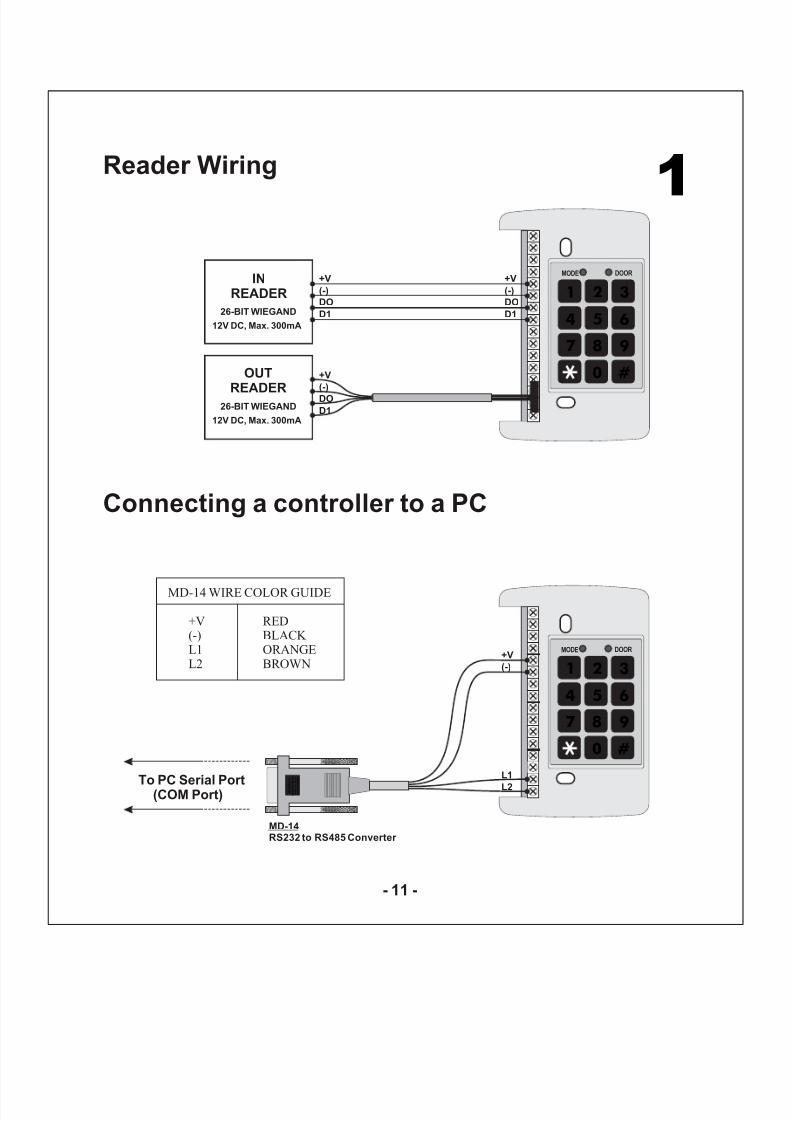
1Reader Wiring
Connecting a controller to a PC
0
8
5
21
4 6
3
97
#
MODE DOOR
INREADER
OUT
READER
+V
(-)
DO
D126-BIT WIEGAND
+V
(-)
DO
D1
+V
(-)
DO
D1
0
8
5
21
4 6
3
97
#
MODE DOOR+V
(-)
L1
L2 M o d e l
N o
: M
D - 1
4
R S 4 8 5
T O
R S 2 3 2
D A T A C O N
V E R T E R
R o s s
l a r e
MD-14 WIRE COLOR GUIDE
+V RED(-) BLACK L1 ORANGEL2 BROWN
To PC Serial Port(COM Port)
12V DC, Max. 300mA
26-BIT WIEGAND
12V DC, Max. 300mA
MD-14RS232 to RS485 Converter
- 11 -
8/6/2019 AC-115 Hardware IM
http://slidepdf.com/reader/full/ac-115-hardware-im 13/58
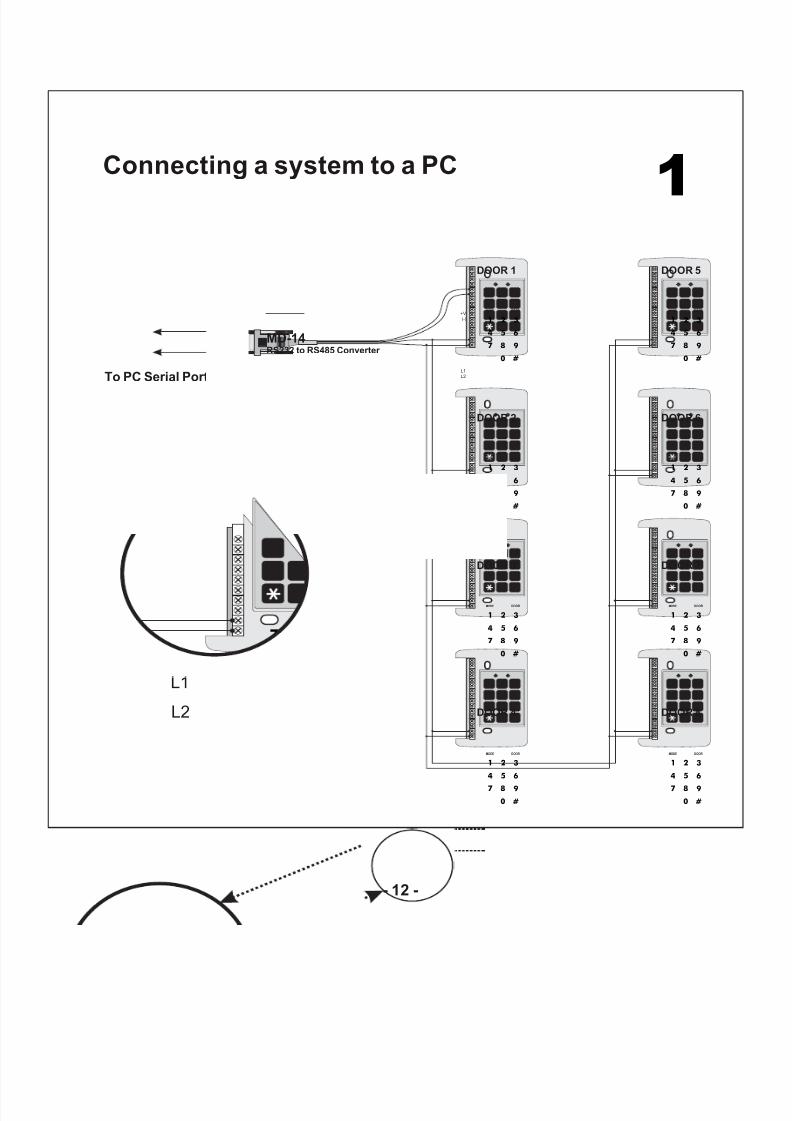
1Connecting a system to a PC
0
8
5
21
4 6
3
97
#
MODE DOOR
0
8
5
21
4 6
3
97
#
MODE DOOR
0
8
5
21
4 6
3
97
#
MODE DOOR
0
8
5
21
4 6
3
97
#
MODE DOOR
0
8
5
21
4 6
3
97
#
MODE DOOR
0
8
5
21
4 6
3
97
#
MODE DOOR
0
8
5
21
4 6
3
97
#
MODE DOOR
0
8
5
21
4 6
3
97
#
MODE DOOR
+V
(-)
L1
L2
DOOR 1
DOOR 2
DOOR 3
DOOR 4
DOOR 5
DOOR 6
DOOR 7
DOOR 8
MD-14RS232 to RS485 Converter
To PC Serial Port
0
87
L1
L2
- 12 -
8/6/2019 AC-115 Hardware IM
http://slidepdf.com/reader/full/ac-115-hardware-im 14/58
Features and Concepts
Now that you have installed your AC-
115 controller or networked system of controllers, it is time to get familiar with its features and concepts.
In this chapter you will learn about allthe features that are programmablewithout the use of the PC software.They are the basic features of the AC-115 and can be programmed directlyfrom the controller’s programmingkeypad.
You will learn about the controller’svarious modes of operation, how toswitch between the Modes of Operation, Special Codes, Events andEvent Actions.
Topics in this Chapter
!
!
!
!
Code Assignment
Modes of Operation
Changing the Modes of Operation
Events and Event Actions
3
- 13 -
8/6/2019 AC-115 Hardware IM
http://slidepdf.com/reader/full/ac-115-hardware-im 15/58
Whenever an employee is added to an AC-115 from the controller’s programming keypad or from a PC, by default the employee code is set toactivate the Lock Strike Output when it is presented to a reader.
Each Employee Code can also be programmed to activate only the AuxiliaryOutput, as well as both the Lock Strike and Auxiliary Outputs at the same time.
Setting which Output(s) are activated when a code is presented to a reader iscalled Code Assignment. See Programming Menu 12 on Page 29 for more detailson Code Assignment.
1Code Assignment (Lock Strike & Auxiliary)
- 14 -
8/6/2019 AC-115 Hardware IM
http://slidepdf.com/reader/full/ac-115-hardware-im 16/58
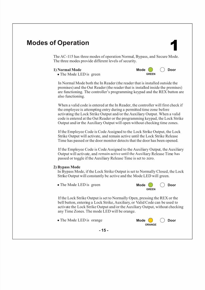
The AC-115 has three modes of operation Normal, Bypass, and Secure Mode.The three modes provide different levels of security.
1) Normal Mode!
!
!
The Mode LED is green
In Normal Mode both the In Reader (the reader that is installed outside the premises) and the Out Reader (the reader that is installed inside the premises)are functioning. The controller’s programming keypad and the REX button arealso functioning.
When a valid code is entered at the In Reader, the controller will first check if the employee is attempting entry during a permitted time zone beforeactivating the Lock Strike Output and/or the Auxiliary Output. When a validcode is entered at the Out Reader or the programming keypad, the Lock StrikeOutput and/or the Auxiliary Output will open without checking time zones.
If the Employee Code is Code Assigned to the Lock Strike Output, the Lock Strike Output will activate, and remain active until the Lock Strike ReleaseTime has passed or the door monitor detects that the door has been opened.
If the Employee Code is Code Assigned to the Auxiliary Output, the Auxiliary
Output will activate, and remain active until the Auxiliary Release Time has passed or toggle if the Auxiliary Release Time is set to zero.
In Bypass Mode, if the Lock Strike Output is set to Normally Closed, the Lock Strike Output will constantly be active and the Mode LED will green.
The Mode LED is green
If the Lock Strike Output is set to Normally Open, pressing the REX or the
bell button, entering a Lock Strike, Auxiliary, or Valid Code can be used toactivate the Lock Strike Output and/or the Auxiliary Output, without checkingany Time Zones. The mode LED will be orange.
The Mode LED is orange
2) Bypass Mode
1Modes of Operation
Mode Door GREEN
Mode Door GREEN
Mode Door ORANGE
- 15 -
8/6/2019 AC-115 Hardware IM
http://slidepdf.com/reader/full/ac-115-hardware-im 17/58
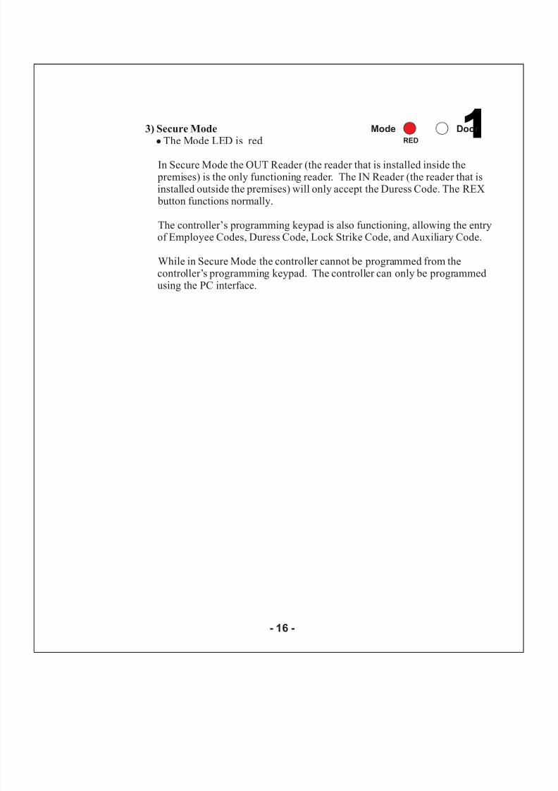
3) Secure Mode! The Mode LED is red
In Secure Mode the OUT Reader (the reader that is installed inside the premises) is the only functioning reader. The IN Reader (the reader that isinstalled outside the premises) will only accept the Duress Code. The REX button functions normally.
The controller’s programming keypad is also functioning, allowing the entryof Employee Codes, Duress Code, Lock Strike Code, and Auxiliary Code.
While in Secure Mode the controller cannot be programmed from the
controller’s programming keypad. The controller can only be programmedusing the PC interface.
1Mode Door
RED
- 16 -
8/6/2019 AC-115 Hardware IM
http://slidepdf.com/reader/full/ac-115-hardware-im 18/58
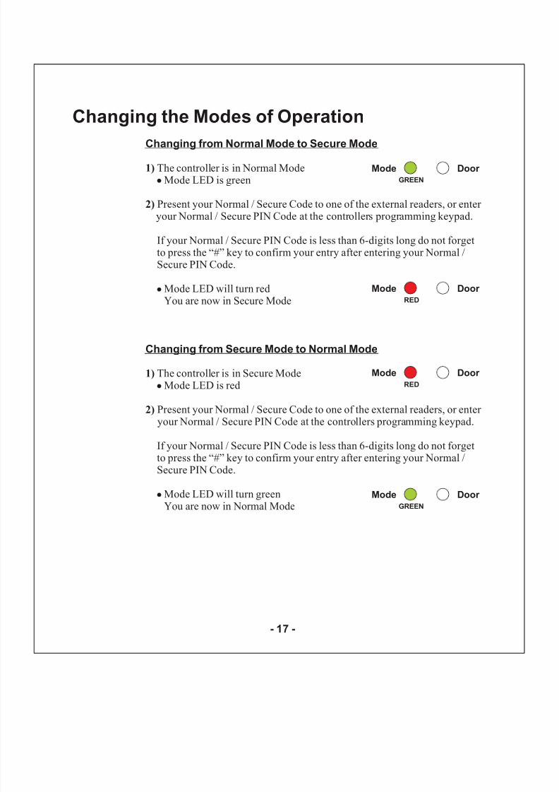
Changing from Normal Mode to Secure Mode
Changing from Secure Mode to Normal Mode
1)
2)
1)
2)
The controller is in Normal ModeMode LED is green
Present your Normal / Secure Code to one of the external readers, or enter your Normal / Secure PIN Code at the controllers programming keypad.
Mode LED will turn redYou are now in Secure Mode
The controller is in Secure ModeMode LED is red
Present your Normal / Secure Code to one of the external readers, or enter your Normal / Secure PIN Code at the controllers programming keypad.
Mode LED will turn greenYou are now in Normal Mode
!
!
!
!
If your Normal / Secure PIN Code is less than 6-digits long do not forgetto press the “#” key to confirm your entry after entering your Normal /Secure PIN Code.
If your Normal / Secure PIN Code is less than 6-digits long do not forgetto press the “#” key to confirm your entry after entering your Normal /Secure PIN Code.
Mode Door GREEN
Changing the Modes of Operation
Mode Door RED
Mode Door RED
Mode Door GREEN
- 17 -
8/6/2019 AC-115 Hardware IM
http://slidepdf.com/reader/full/ac-115-hardware-im 19/58
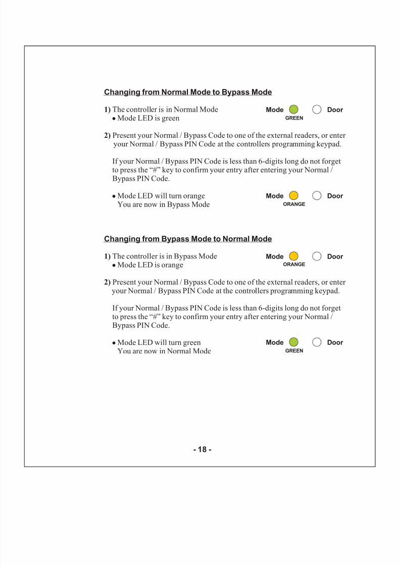
Changing from Normal Mode to Bypass Mode
Changing from Bypass Mode to Normal Mode
1)
2)
1)
2)
The controller is in Normal ModeMode LED is green
Present your Normal / Bypass Code to one of the external readers, or enter your Normal / Bypass PIN Code at the controllers programming keypad.
Mode LED will turn orangeYou are now in Bypass Mode
The controller is in Bypass ModeMode LED is orange
Present your Normal / Bypass Code to one of the external readers, or enter your Normal / Bypass PIN Code at the controllers programming keypad.
Mode LED will turn greenYou are now in Normal Mode
!
!
!
!
If your Normal / Bypass PIN Code is less than 6-digits long do not forgetto press the “#” key to confirm your entry after entering your Normal /Bypass PIN Code.
If your Normal / Bypass PIN Code is less than 6-digits long do not forgetto press the “#” key to confirm your entry after entering your Normal /Bypass PIN Code.
Mode Door GREEN
Mode Door ORANGE
Mode Door
Mode Door GREEN
ORANGE
- 18 -
8/6/2019 AC-115 Hardware IM
http://slidepdf.com/reader/full/ac-115-hardware-im 20/58
All of the AC-115’s key features are triggered by some events. For instance placing a valid code at the reader at the right time is an Event, and the Valid CodeEvent may trigger the Lock Strike Output to activate an Event Action.
In this section you will learn about the AC-115’s Events and the Event Actionsthose Events cause.
The Monitor Event is triggered when the Door Monitor Switch has been
activated, i.e. the door has been opened.
Chime AlertDoor Ajar Event if door is not closed in timeForced Door Event if valid code was not entered
A door is considered ajar when the Door Monitor Switch has been activatedwith a Valid Code being entered. If the door is left open longer than the Ajar Delay Time, a Door Ajar Event will occur..
Siren Event (Programmable Siren Time)Auxiliary Output Activation (Programmable Auxiliary Release Time)
A door is considered forced open when the Door Monitor Switch has beenactivated without a Valid Code being entered. When this occurs a Forced Door
Delay Time will count down. When the count is done, the Forced Door Eventwill occur.
Siren Event (Programmable Siren Time)Auxiliary Output Activation (Programmable Auxiliary Release Time)
Monitor Event
Door Ajar Event
Forced Door Event
Possible Monitor Event Actions
Possible Ajar Door Event Actions
Possible Forced Door Event Actions
1Events and Event Actions
8/6/2019 AC-115 Hardware IM
http://slidepdf.com/reader/full/ac-115-hardware-im 21/58
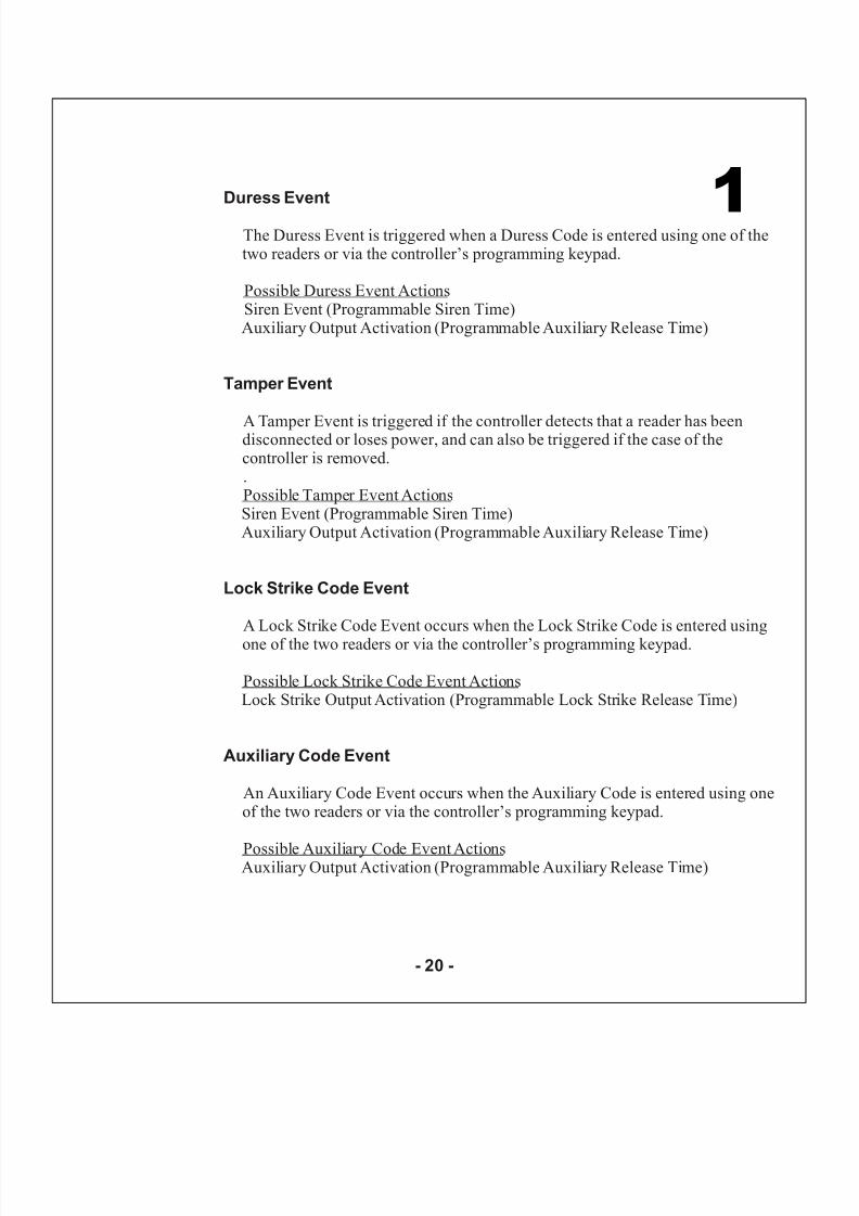
Duress Event
Tamper Event
Lock Strike Code Event
Auxiliary Code Event
The Duress Event is triggered when a Duress Code is entered using one of thetwo readers or via the controller’s programming keypad.
Siren Event (Programmable Siren Time)Auxiliary Output Activation (Programmable Auxiliary Release Time)
A Tamper Event is triggered if the controller detects that a reader has beendisconnected or loses power, and can also be triggered if the case of thecontroller is removed..
Siren Event (Programmable Siren Time)Auxiliary Output Activation (Programmable Auxiliary Release Time)
A Lock Strike Code Event occurs when the Lock Strike Code is entered using
one of the two readers or via the controller’s programming keypad.
Lock Strike Output Activation (Programmable Lock Strike Release Time)
An Auxiliary Code Event occurs when the Auxiliary Code is entered using oneof the two readers or via the controller’s programming keypad.
Auxiliary Output Activation (Programmable Auxiliary Release Time)
Possible Duress Event Actions
Possible Tamper Event Actions
Possible Lock Strike Code Event Actions
Possible Auxiliary Code Event Actions
1
- 20 -
8/6/2019 AC-115 Hardware IM
http://slidepdf.com/reader/full/ac-115-hardware-im 22/58
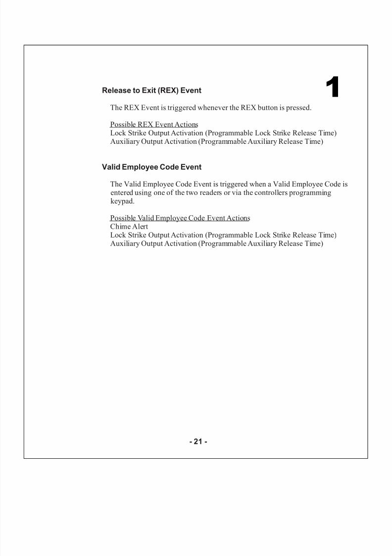
Release to Exit (REX) Event
Valid Employee Code Event
The REX Event is triggered whenever the REX button is pressed.
Lock Strike Output Activation (Programmable Lock Strike Release Time)Auxiliary Output Activation (Programmable Auxiliary Release Time)
The Valid Employee Code Event is triggered when a Valid Employee Code is
entered using one of the two readers or via the controllers programmingkeypad.
Chime AlertLock Strike Output Activation (Programmable Lock Strike Release Time)Auxiliary Output Activation (Programmable Auxiliary Release Time)
Possible REX Event Actions
Possible Valid Employee Code Event Actions
1
- 21 -

8/6/2019 AC-115 Hardware IM
http://slidepdf.com/reader/full/ac-115-hardware-im 23/58
Programming Instructions
After reading Chapter 3 - Features and
Concepts, you should already have anunderstanding of the AC-115’s features.
Most of these features can be programmed via the AC-115’s programming keypad. The following pages describe how to program the AC-115 using the programming keypad.
Topics in this Chapter
!
!
Programming Manual
Programming Quick Reference
Guide
4
- 22 -
8/6/2019 AC-115 Hardware IM
http://slidepdf.com/reader/full/ac-115-hardware-im 24/58
8/6/2019 AC-115 Hardware IM
http://slidepdf.com/reader/full/ac-115-hardware-im 25/58
8/6/2019 AC-115 Hardware IM
http://slidepdf.com/reader/full/ac-115-hardware-im 26/58
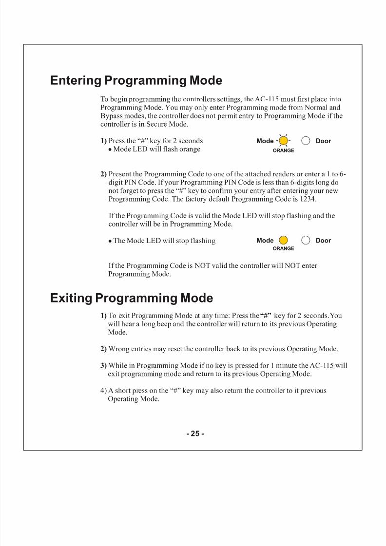
To begin programming the controllers settings, the AC-115 must first place intoProgramming Mode. You may only enter Programming mode from Normal andBypass modes, the controller does not permit entry to Programming Mode if thecontroller is in Secure Mode.
Press the “#” key for 2 secondsMode LED will flash orange
The Mode LED will stop flashing
Youwill hear a long beep and the controller will return to its previous OperatingMode.
Wrong entries may reset the controller back to its previous Operating Mode.
While in Programming Mode if no key is pressed for 1 minute the AC-115 willexit programming mode and return to its previous Operating Mode.
4) A short press on the “#” key may also return the controller to it previousOperating Mode.
1)
2)
2)
3)
!
!
Present the Programming Code to one of the attached readers or enter a 1 to 6-digit PIN Code. If your Programming PIN Code is less than 6-digits long do
not forget to press the “#” key to confirm your entry after entering your newProgramming Code. The factory default Programming Code is 1234.
If the Programming Code is valid the Mode LED will stop flashing and thecontroller will be in Programming Mode.
If the Programming Code is NOT valid the controller will NOT enter Programming Mode.
To exit Programming Mode at any time: Press the key for 2 seconds.1) “#”
Mode Door
ORANGE
Entering Programming Mode
Mode Door ORANGE
Exiting Programming Mode
- 25 -
8/6/2019 AC-115 Hardware IM
http://slidepdf.com/reader/full/ac-115-hardware-im 27/58
1)
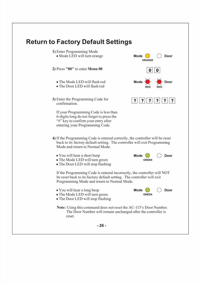
2) "00" Menu 00
3)
4)
Note:
Enter Programming ModeMode LED will turn orange
Press to enter
The Mode LED will flash redThe Door LED will flash red
Enter the Programming Code for confirmation.
If the Programming Code is entered correctly, the controller will be reset back to its factory default setting. The controller will exit ProgrammingMode and return to Normal Mode.
You will hear a short beepThe Mode LED will turn greenThe Door LED will stop flashing
If the Programming Code is entered incorrectly, the controller will NOT be reset back to its factory default setting. The controller will exitProgramming Mode and return to Normal Mode.
You will hear a long beepThe Mode LED will turn green
The Door LED will stop flashing
Using this command does not reset the AC-115’s Door Number.The Door Number will remain unchanged after the controller isreset.
!
!
!
!
!
!
!
!
!
If your Programming Code is less than6-digits long do not forget to press the“#” key to confirm your entry after entering your Programming Code.
Mode Door ORANGE
Mode Door
RED
0 0
Mode Door
GREEN
? ?
RED
? ? ? ?
Mode Door GREEN
Return to Factory Default Settings
- 26 -
8/6/2019 AC-115 Hardware IM
http://slidepdf.com/reader/full/ac-115-hardware-im 28/58
1)
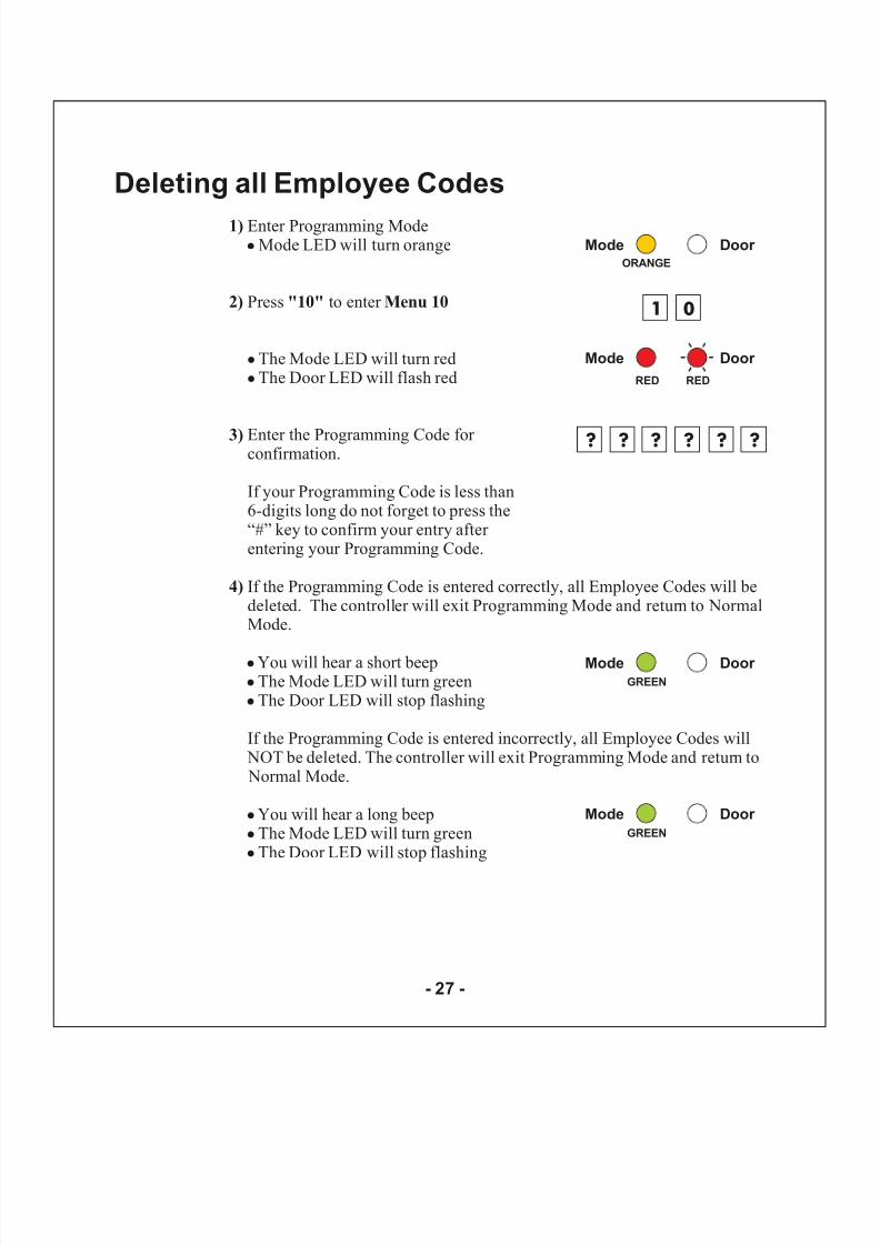
2) "10" Menu 10
3)
4)
Enter Programming ModeMode LED will turn orange
Press to enter
The Mode LED will turn redThe Door LED will flash red
Enter the Programming Code for confirmation.
If the Programming Code is entered correctly, all Employee Codes will bedeleted. The controller will exit Programming Mode and return to NormalMode.
You will hear a short beepThe Mode LED will turn greenThe Door LED will stop flashing
If the Programming Code is entered incorrectly, all Employee Codes will NOT be deleted. The controller will exit Programming Mode and return to Normal Mode.
You will hear a long beepThe Mode LED will turn greenThe Door LED will stop flashing
!
!
!
!
!
!
!
!
!
If your Programming Code is less than6-digits long do not forget to press the“#” key to confirm your entry after entering your Programming Code.
Mode Door ORANGE
Mode Door
RED
1 0
Mode Door
GREEN
? ?
RED
? ? ? ?
Mode Door GREEN
Deleting all Employee Codes
- 27 -
8/6/2019 AC-115 Hardware IM
http://slidepdf.com/reader/full/ac-115-hardware-im 29/58
1)
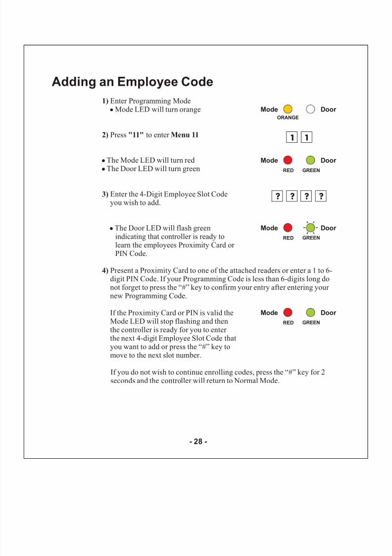
2) "11" Menu 11
3)
4)
Enter Programming ModeMode LED will turn orange
Press to enter
The Mode LED will turn redThe Door LED will turn green
Enter the 4-Digit Employee Slot Codeyou wish to add.
The Door LED will flash greenindicating that controller is ready tolearn the employees Proximity Card or PIN Code.
Present a Proximity Card to one of the attached readers or enter a 1 to 6-digit PIN Code. If your Programming Code is less than 6-digits long donot forget to press the “#” key to confirm your entry after entering your new Programming Code.
If the Proximity Card or PIN is valid theMode LED will stop flashing and thenthe controller is ready for you to enter the next 4-digit Employee Slot Code thatyou want to add or press the “#” key tomove to the next slot number.
If you do not wish to continue enrolling codes, press the “#” key for 2seconds and the controller will return to Normal Mode.
!
!
!
!
Mode Door ORANGE
Mode Door
RED
1 1
? ?
GREEN
? ?
Mode Door
RED GREEN
Mode Door
RED GREEN
Adding an Employee Code
- 28 -
8/6/2019 AC-115 Hardware IM
http://slidepdf.com/reader/full/ac-115-hardware-im 30/58
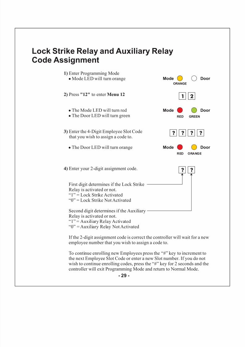
1)
2) "12" Menu 12
3)
4)
Enter Programming ModeMode LED will turn orange
Press to enter
The Mode LED will turn redThe Door LED will turn green
Enter the 4-Digit Employee Slot Codethat you wish to assign a code to.
The Door LED will turn orange
Enter your 2-digit assignment code.
First digit determines if the Lock StrikeRelay is activated or not.“1” = Lock Strike Activated“0” = Lock Strike Not Activated
Second digit determines if the AuxiliaryRelay is activated or not.“1” = Auxiliary Relay Activated“0” = Auxiliary Relay Not Activated
If the 2-digit assignment code is correct the controller will wait for a new
employee number that you wish to assign a code to.
To continue enrolling new Employees press the “#” key to increment tothe next Employee Slot Code or enter a new Slot number. If you do notwish to continue enrolling codes, press the “#” key for 2 seconds and thecontroller will exit Programming Mode and return to Normal Mode.
!
!
!
!
Mode Door ORANGE
Mode Door
RED
1 2
? ?
GREEN
? ?
? ?
Mode Door
RED ORANGE
Lock Strike Relay and Auxiliary Relay
Code Assignment
- 29 -
8/6/2019 AC-115 Hardware IM
http://slidepdf.com/reader/full/ac-115-hardware-im 31/58
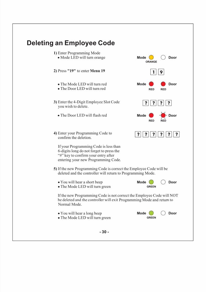
1)
2) "19" Menu 19
3)
4)
5)
Enter Programming ModeMode LED will turn orange
Press to enter
The Mode LED will turn redThe Door LED will turn red
Enter the 4-Digit Employee Slot Codeyou wish to delete.
The Door LED will flash red
Enter your Programming Code toconfirm the deletion.
If your Programming Code is less than6-digits long do not forget to press the“#” key to confirm your entry after entering your new Programming Code.
If the new Programming Code is correct the Employee Code will bedeleted and the controller will return to Programming Mode.
You will hear a short beepThe Mode LED will turn green
If the new Programming Code is not correct the Employee Code will NOT be deleted and the controller will exit Programming Mode and return to
Normal Mode.
You will hear a long beepThe Mode LED will turn green
!
!
!
!
!
!
!
!
Mode Door ORANGE
Mode Door
RED
1 9
Mode Door GREEN
? ?
RED
? ?
? ? ? ? ? ?
Mode Door
RED RED
Mode Door
GREEN
Deleting an Employee Code
- 30 -
8/6/2019 AC-115 Hardware IM
http://slidepdf.com/reader/full/ac-115-hardware-im 32/58
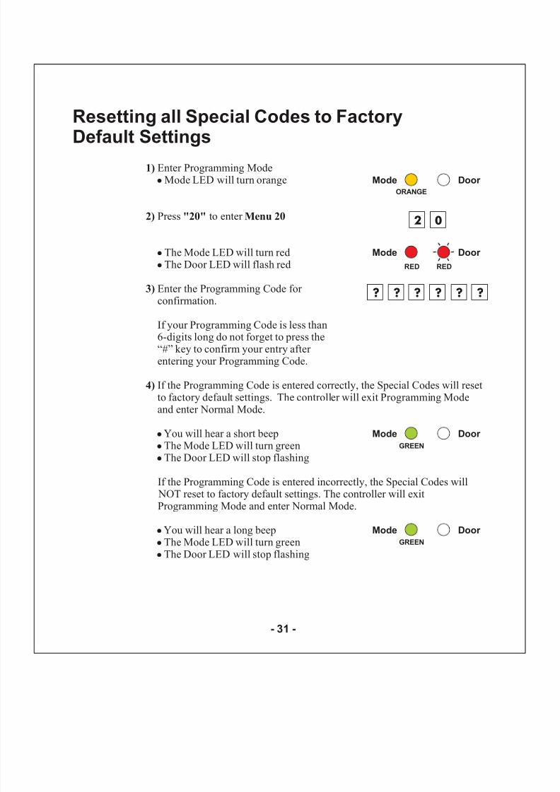
1)
2) "20" Menu 20
3)
4)
Enter Programming ModeMode LED will turn orange
Press to enter
The Mode LED will turn redThe Door LED will flash red
Enter the Programming Code for confirmation.
If the Programming Code is entered correctly, the Special Codes will resetto factory default settings. The controller will exit Programming Modeand enter Normal Mode.
You will hear a short beepThe Mode LED will turn greenThe Door LED will stop flashing
If the Programming Code is entered incorrectly, the Special Codes will NOT reset to factory default settings. The controller will exitProgramming Mode and enter Normal Mode.
You will hear a long beepThe Mode LED will turn green
The Door LED will stop flashing
!
!
!
!
!
!
!
!
!
If your Programming Code is less than6-digits long do not forget to press the“#” key to confirm your entry after entering your Programming Code.
Mode Door ORANGE
Mode Door
RED
2 0
Mode Door GREEN
? ?
RED
? ? ? ?
Mode Door
GREEN
Resetting all Special Codes to Factory
Default Settings
- 31 -
8/6/2019 AC-115 Hardware IM
http://slidepdf.com/reader/full/ac-115-hardware-im 33/58
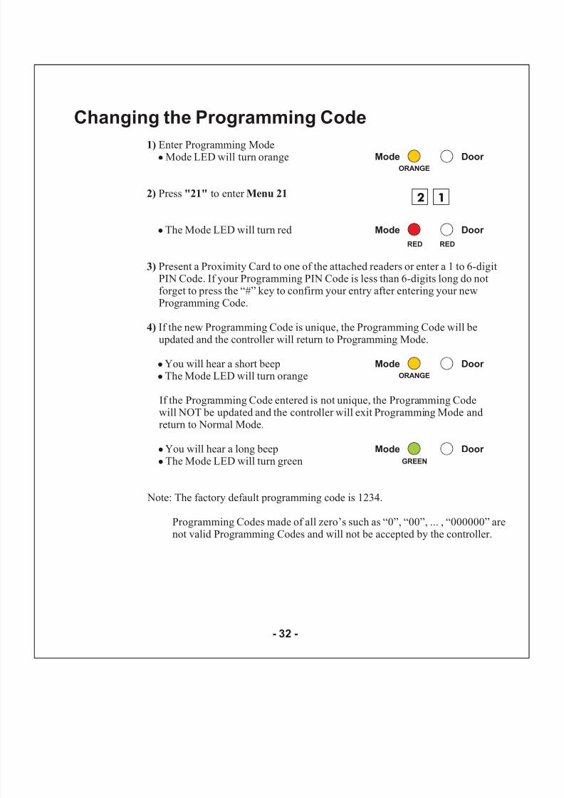
1)
2) "21" Menu 21
3)
4)
Enter Programming ModeMode LED will turn orange
Press to enter
The Mode LED will turn red
Present a Proximity Card to one of the attached readers or enter a 1 to 6-digit
PIN Code. If your Programming PIN Code is less than 6-digits long do notforget to press the “#” key to confirm your entry after entering your newProgramming Code.
If the new Programming Code is unique, the Programming Code will beupdated and the controller will return to Programming Mode.
You will hear a short beepThe Mode LED will turn orange
If the Programming Code entered is not unique, the Programming Codewill NOT be updated and the controller will exit Programming Mode andreturn to Normal Mode.
You will hear a long beepThe Mode LED will turn green
Note: The factory default programming code is 1234.
Programming Codes made of all zero’s such as “0”, “00”, ... , “000000” arenot valid Programming Codes and will not be accepted by the controller.
!
!
!
!
!
!
Mode Door ORANGE
Mode Door
RED
2 1
Mode Door
GREEN
RED
Mode Door ORANGE
Changing the Programming Code
- 32 -
8/6/2019 AC-115 Hardware IM
http://slidepdf.com/reader/full/ac-115-hardware-im 34/58
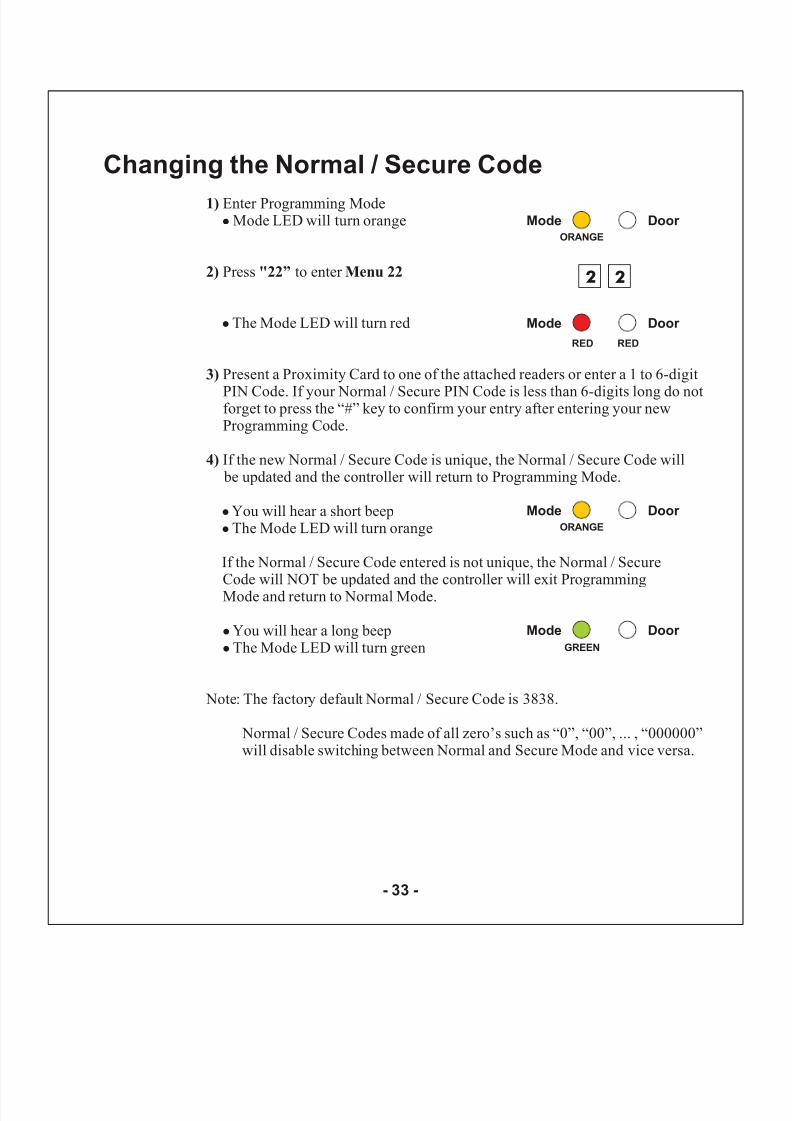
1)
2) "22” Menu 22
3)
4)
Enter Programming ModeMode LED will turn orange
Press to enter
The Mode LED will turn red
Present a Proximity Card to one of the attached readers or enter a 1 to 6-digit
PIN Code. If your Normal / Secure PIN Code is less than 6-digits long do notforget to press the “#” key to confirm your entry after entering your newProgramming Code.
If the new Normal / Secure Code is unique, the Normal / Secure Code will be updated and the controller will return to Programming Mode.
You will hear a short beepThe Mode LED will turn orange
If the Normal / Secure Code entered is not unique, the Normal / SecureCode will NOT be updated and the controller will exit ProgrammingMode and return to Normal Mode.
You will hear a long beepThe Mode LED will turn green
Note: The factory default Normal / Secure Code is 3838.
Normal / Secure Codes made of all zero’s such as “0”, “00”, ... , “000000”will disable switching between Normal and Secure Mode and vice versa.
!
!
!
!
!
!
Mode Door ORANGE
Mode Door
RED
2 2
Mode Door
GREEN
RED
Mode Door ORANGE
Changing the Normal / Secure Code
- 33 -
8/6/2019 AC-115 Hardware IM
http://slidepdf.com/reader/full/ac-115-hardware-im 35/58
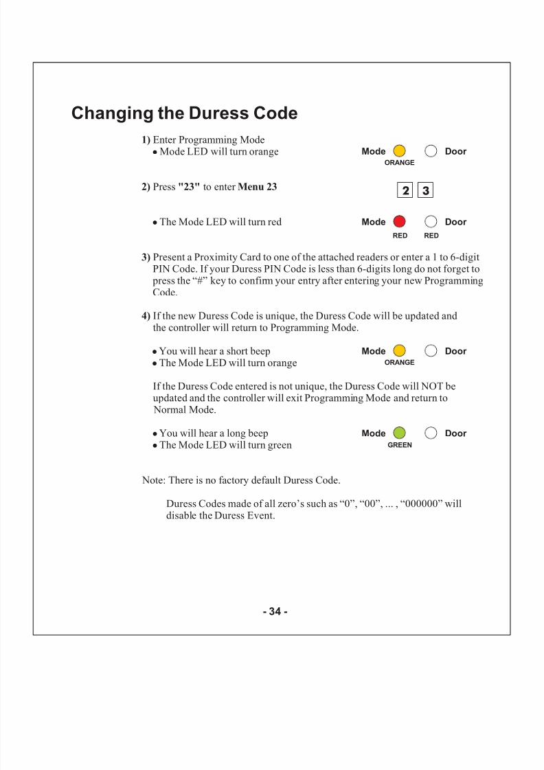
1)
2) "23" Menu 23
3)
4)
Enter Programming ModeMode LED will turn orange
Press to enter
The Mode LED will turn red
Present a Proximity Card to one of the attached readers or enter a 1 to 6-digit
PIN Code. If your Duress PIN Code is less than 6-digits long do not forget to press the “#” key to confirm your entry after entering your new ProgrammingCode.
If the new Duress Code is unique, the Duress Code will be updated andthe controller will return to Programming Mode.
You will hear a short beepThe Mode LED will turn orange
If the Duress Code entered is not unique, the Duress Code will NOT beupdated and the controller will exit Programming Mode and return to Normal Mode.
You will hear a long beepThe Mode LED will turn green
Note: There is no factory default Duress Code.
Duress Codes made of all zero’s such as “0”, “00”, ... , “000000” willdisable the Duress Event.
!
!
!
!
!
!
Mode Door ORANGE
Mode Door
RED
2 3
Mode Door GREEN
RED
Mode Door ORANGE
Changing the Duress Code
- 34 -
8/6/2019 AC-115 Hardware IM
http://slidepdf.com/reader/full/ac-115-hardware-im 36/58
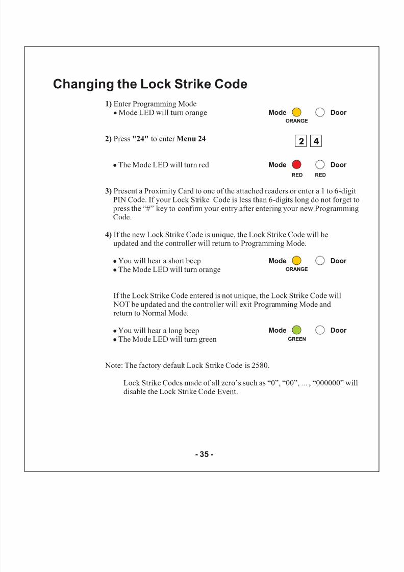
1)
2) "24" Menu 24
3)
4)
Enter Programming ModeMode LED will turn orange
Press to enter
The Mode LED will turn red
Present a Proximity Card to one of the attached readers or enter a 1 to 6-digit
PIN Code. If your Lock Strike Code is less than 6-digits long do not forget to press the “#” key to confirm your entry after entering your new ProgrammingCode.
If the new Lock Strike Code is unique, the Lock Strike Code will beupdated and the controller will return to Programming Mode.
You will hear a short beepThe Mode LED will turn orange
If the Lock Strike Code entered is not unique, the Lock Strike Code will NOT be updated and the controller will exit Programming Mode andreturn to Normal Mode.
You will hear a long beepThe Mode LED will turn green
Note: The factory default Lock Strike Code is 2580.
Lock Strike Codes made of all zero’s such as “0”, “00”, ... , “000000” willdisable the Lock Strike Code Event.
!
!
!
!
!
!
Mode Door ORANGE
Mode Door
RED
2 4
Mode Door
GREEN
RED
Mode Door ORANGE
Changing the Lock Strike Code
- 35 -

8/6/2019 AC-115 Hardware IM
http://slidepdf.com/reader/full/ac-115-hardware-im 37/58
1)
2) "25" Menu 25
3)
4)
Enter Programming ModeMode LED will turn orange
Press to enter
The Mode LED will turn red
Present a Proximity Card to one of the attached readers or enter a 1 to 6-digit
PIN Code. If your Auxiliary PIN Code is less than 6-digits long do not forgetto press the “#” key to confirm your entry after entering your newProgramming Code.
If the new Auxiliary Code is unique, the Auxiliary Code will be updatedand the controller will return to Programming Mode.
You will hear a short beepThe Mode LED will turn orange
If the Auxiliary Code entered is not unique, the Auxiliary Code will NOT be updated and the controller will exit Programming Mode and return to Normal Mode.
You will hear a long beepThe Mode LED will turn green
Note: There is no factory default Auxiliary Code.
Auxiliary Codes made of all zero’s such as “0”, “00”, ... , “000000” willdisable the Auxiliary Code Event.
!
!
!
!
!
!
Mode Door ORANGE
Mode Door
RED
2 5
Mode Door
GREEN
RED
Mode Door ORANGE
Changing the Auxiliary Code
- 36 -
8/6/2019 AC-115 Hardware IM
http://slidepdf.com/reader/full/ac-115-hardware-im 38/58
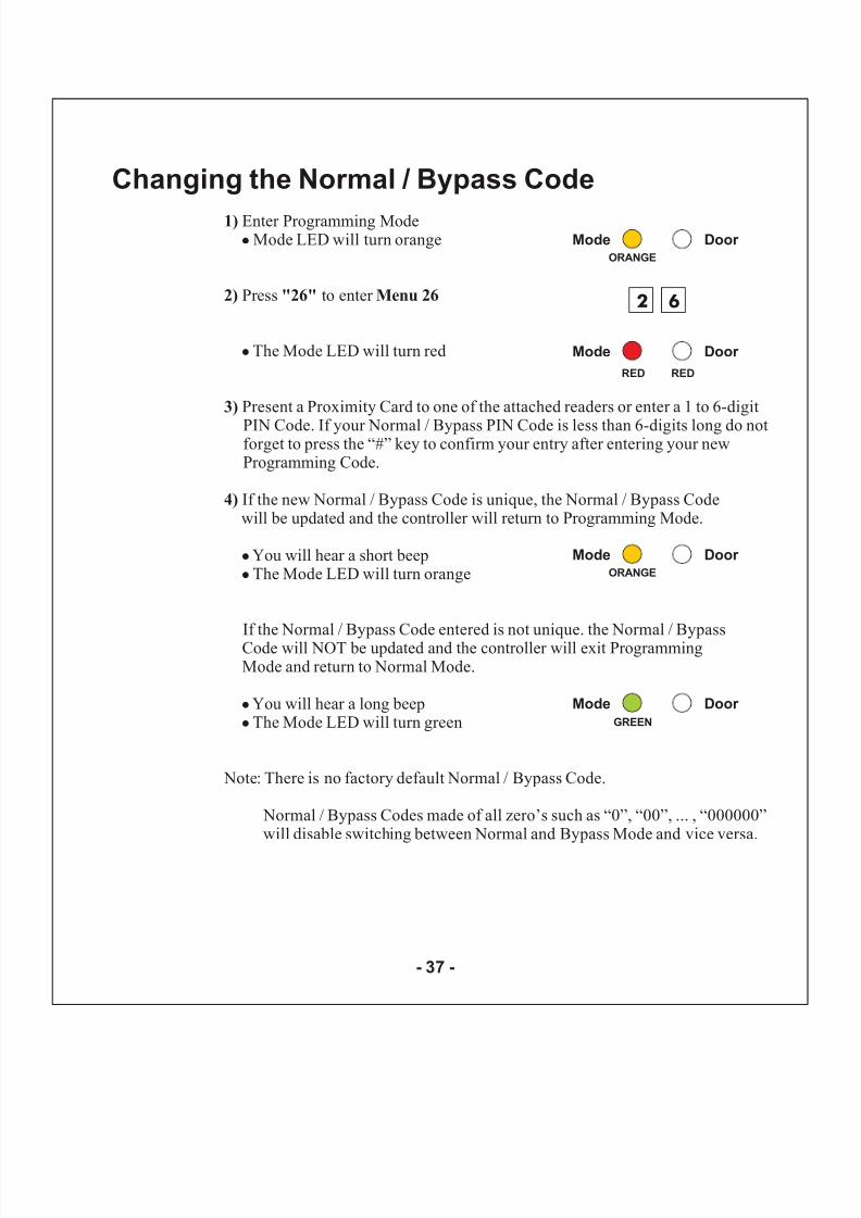
1)
2) "26" Menu 26
3)
4)
Enter Programming ModeMode LED will turn orange
Press to enter
The Mode LED will turn red
Present a Proximity Card to one of the attached readers or enter a 1 to 6-digit
PIN Code. If your Normal / Bypass PIN Code is less than 6-digits long do notforget to press the “#” key to confirm your entry after entering your newProgramming Code.
If the new Normal / Bypass Code is unique, the Normal / Bypass Codewill be updated and the controller will return to Programming Mode.
You will hear a short beepThe Mode LED will turn orange
If the Normal / Bypass Code entered is not unique. the Normal / BypassCode will NOT be updated and the controller will exit ProgrammingMode and return to Normal Mode.
You will hear a long beepThe Mode LED will turn green
Note: There is no factory default Normal / Bypass Code.
Normal / Bypass Codes made of all zero’s such as “0”, “00”, ... , “000000”will disable switching between Normal and Bypass Mode and vice versa.
!
!
!
!
!
!
Mode Door ORANGE
Mode Door
RED
2 6
Mode Door GREEN
RED
Mode Door ORANGE
Changing the Normal / Bypass Code
- 37 -
8/6/2019 AC-115 Hardware IM
http://slidepdf.com/reader/full/ac-115-hardware-im 39/58
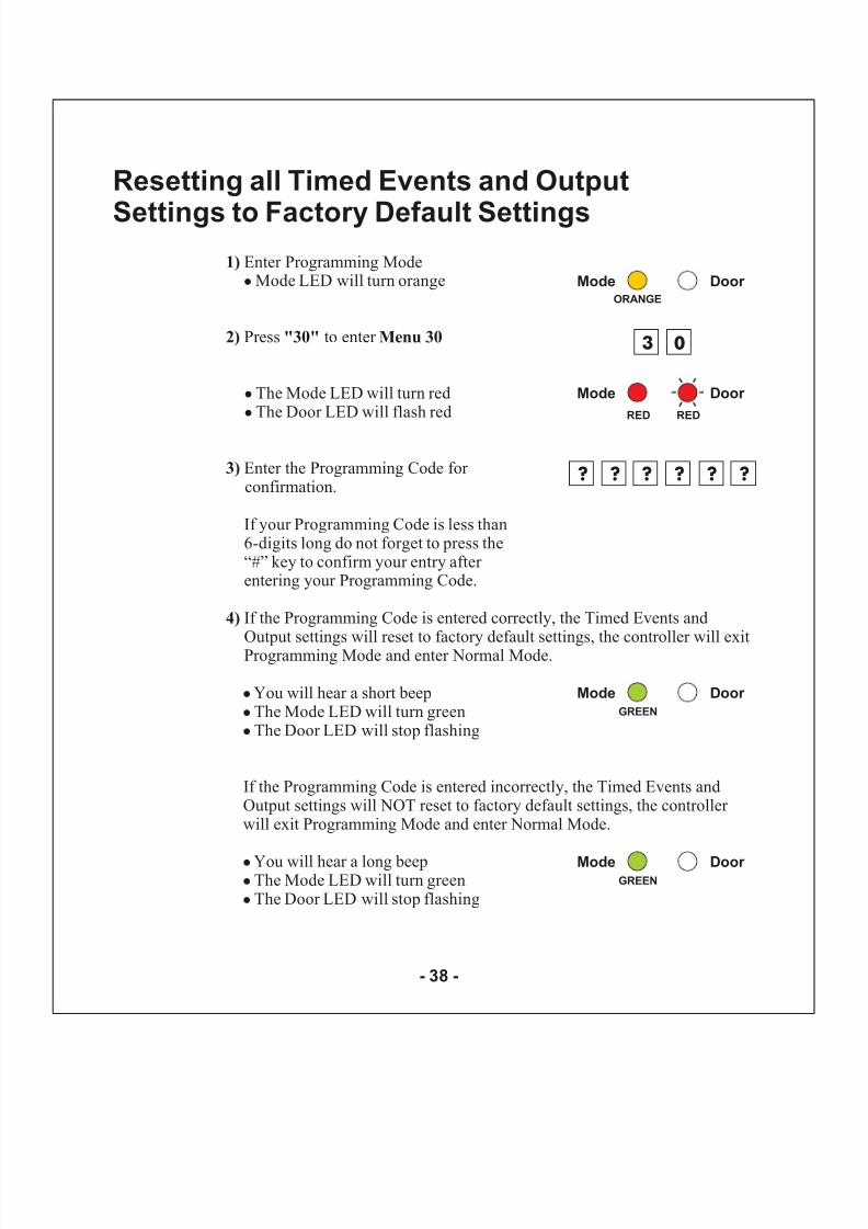
1)
2) "30" Menu 30
3)
4)
Enter Programming ModeMode LED will turn orange
Press to enter
The Mode LED will turn redThe Door LED will flash red
Enter the Programming Code for confirmation.
If the Programming Code is entered correctly, the Timed Events andOutput settings will reset to factory default settings, the controller will exitProgramming Mode and enter Normal Mode.
You will hear a short beepThe Mode LED will turn greenThe Door LED will stop flashing
If the Programming Code is entered incorrectly, the Timed Events andOutput settings will NOT reset to factory default settings, the controller will exit Programming Mode and enter Normal Mode.
You will hear a long beepThe Mode LED will turn greenThe Door LED will stop flashing
!
!
!
!
!
!
!
!
!
If your Programming Code is less than6-digits long do not forget to press the“#” key to confirm your entry after entering your Programming Code.
Mode Door ORANGE
Mode Door
RED
3 0
Mode Door GREEN
? ?
RED
? ? ? ?
Mode Door GREEN
Resetting all Timed Events and Output
Settings to Factory Default Settings
- 38 -
8/6/2019 AC-115 Hardware IM
http://slidepdf.com/reader/full/ac-115-hardware-im 40/58
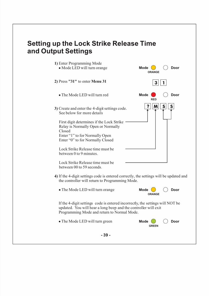
1)
2) "31" Menu 31
3)
4)
Enter Programming ModeMode LED will turn orange
Press to enter
The Mode LED will turn red
Create and enter the 4-digit settings code.See below for more details
First digit determines if the Lock StrikeRelay is Normally Open or NormallyClosedEnter “1” to for Normally OpenEnter “0” to for Normally Closed
Lock Strike Release time must be
between 0 to 9 minutes.
Lock Strike Release time must be between 00 to 59 seconds.
If the 4-digit settings code is entered correctly, the settings will be updated andthe controller will return to Programming Mode.
The Mode LED will turn orange
If the 4-digit settings code is entered incorrectly, the settings will NOT be
updated. You will hear a long beep and the controller will exitProgramming Mode and return to Normal Mode.
The Mode LED will turn green
!
!
!
!
Mode Door ORANGE
Mode Door
RED
3 1
Mode Door GREEN
Mode Door ORANGE
? M S S
Setting up the Lock Strike Release Time
and Output Settings
- 39 -
8/6/2019 AC-115 Hardware IM
http://slidepdf.com/reader/full/ac-115-hardware-im 41/58
8/6/2019 AC-115 Hardware IM
http://slidepdf.com/reader/full/ac-115-hardware-im 42/58
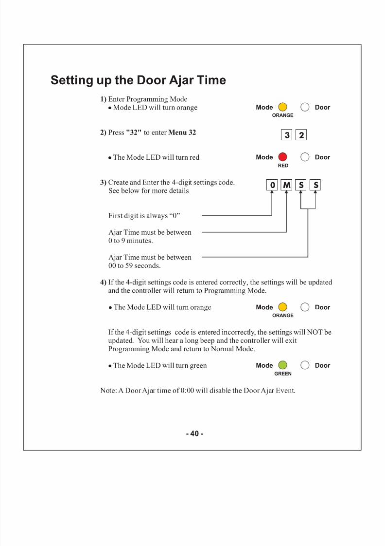
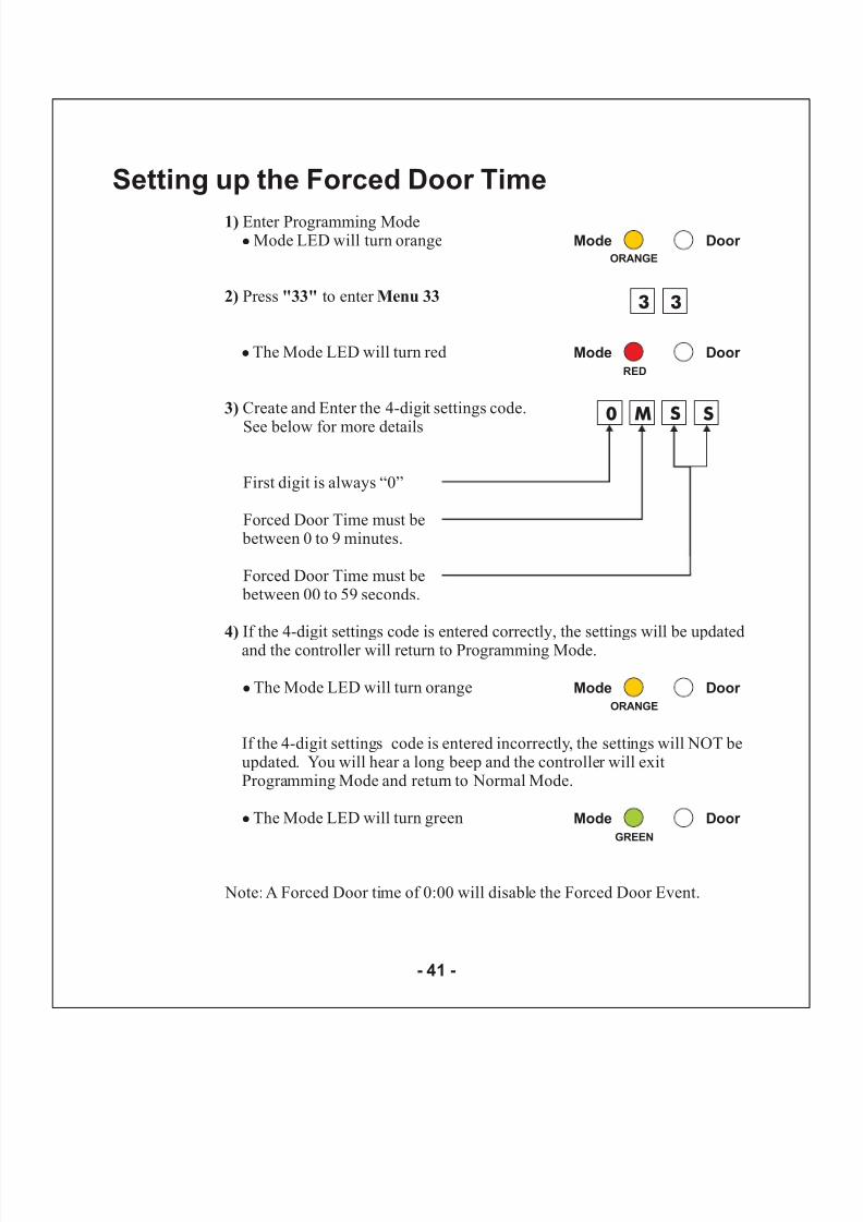
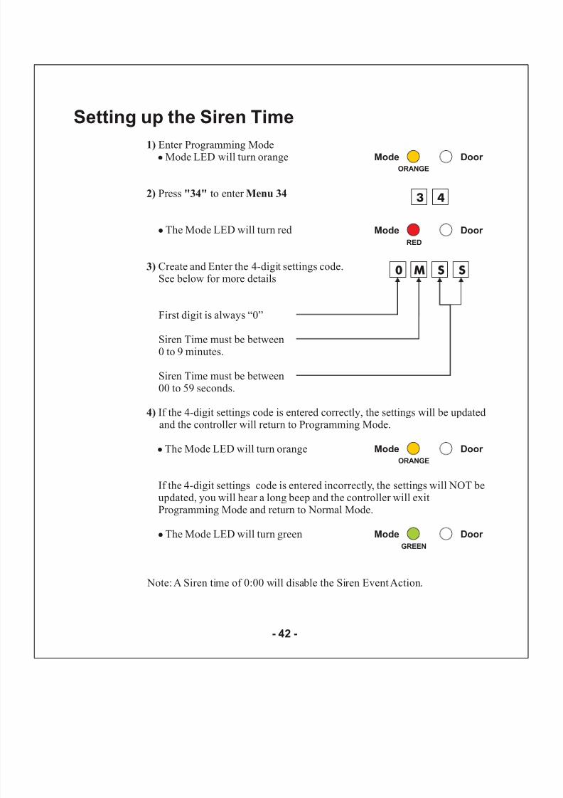
1)
2) "33" Menu 33
3)
4)
Enter Programming ModeMode LED will turn orange
Press to enter
The Mode LED will turn red
Create and Enter the 4-digit settings code.
See below for more details
First digit is always “0”
Forced Door Time must be between 0 to 9 minutes.
Forced Door Time must be between 00 to 59 seconds.
If the 4-digit settings code is entered correctly, the settings will be updatedand the controller will return to Programming Mode.
The Mode LED will turn orange
If the 4-digit settings code is entered incorrectly, the settings will NOT beupdated. You will hear a long beep and the controller will exitProgramming Mode and return to Normal Mode.
The Mode LED will turn green
!
!
!
!
Note: A Forced Door time of 0:00 will disable the Forced Door Event.
Mode Door ORANGE
Mode Door
RED
3 3
Mode Door
GREEN
Mode Door ORANGE
0 M S S
Setting up the Forced Door Time
- 41 -
8/6/2019 AC-115 Hardware IM
http://slidepdf.com/reader/full/ac-115-hardware-im 43/58
8/6/2019 AC-115 Hardware IM
http://slidepdf.com/reader/full/ac-115-hardware-im 44/58
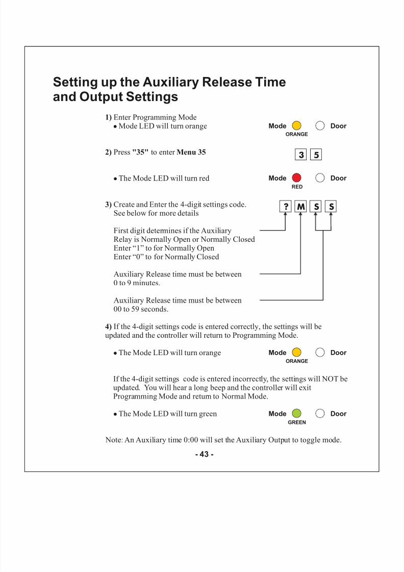
1)
2) "35" Menu 35
3)
4)
Enter Programming ModeMode LED will turn orange
Press to enter
The Mode LED will turn red
Create and Enter the 4-digit settings code.See below for more details
First digit determines if the AuxiliaryRelay is Normally Open or Normally ClosedEnter “1” to for Normally OpenEnter “0” to for Normally Closed
Auxiliary Release time must be between0 to 9 minutes.
Auxiliary Release time must be between00 to 59 seconds.
If the 4-digit settings code is entered correctly, the settings will beupdated and the controller will return to Programming Mode.
The Mode LED will turn orange
If the 4-digit settings code is entered incorrectly, the settings will NOT beupdated. You will hear a long beep and the controller will exitProgramming Mode and return to Normal Mode.
The Mode LED will turn green
!
!
!
!
Note: An Auxiliary time 0:00 will set the Auxiliary Output to toggle mode.
Mode Door ORANGE
Mode Door RED
3 5
Mode Door GREEN
Mode Door ORANGE
? M S S
Setting up the Auxiliary Release Time
and Output Settings
- 43 -
8/6/2019 AC-115 Hardware IM
http://slidepdf.com/reader/full/ac-115-hardware-im 45/58
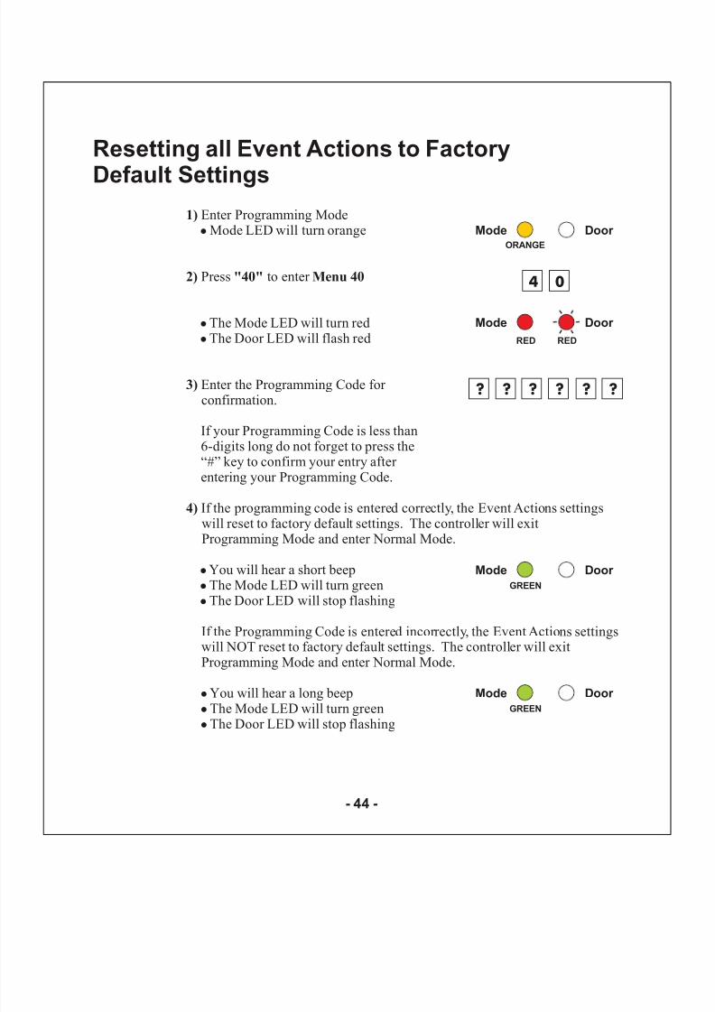
1)
2) "40" Menu 40
3)
4)
Enter Programming ModeMode LED will turn orange
Press to enter
The Mode LED will turn redThe Door LED will flash red
Enter the Programming Code for confirmation.
If the programming code is entered correctly, the Event Actions settingswill reset to factory default settings. The controller will exitProgramming Mode and enter Normal Mode.
You will hear a short beepThe Mode LED will turn greenThe Door LED will stop flashing
If the Programming Code is entered incorrectly, the Event Actions settingswill NOT reset to factory default settings. The controller will exitProgramming Mode and enter Normal Mode.
You will hear a long beep
The Mode LED will turn greenThe Door LED will stop flashing
!
!
!
!
!
!
!
!
!
If your Programming Code is less than6-digits long do not forget to press the“#” key to confirm your entry after entering your Programming Code.
Mode Door ORANGE
Mode Door
RED
4 0
Mode Door
GREEN
? ?
RED
? ? ? ?
Mode Door
GREEN
Resetting all Event Actions to Factory
Default Settings
- 44 -
8/6/2019 AC-115 Hardware IM
http://slidepdf.com/reader/full/ac-115-hardware-im 46/58
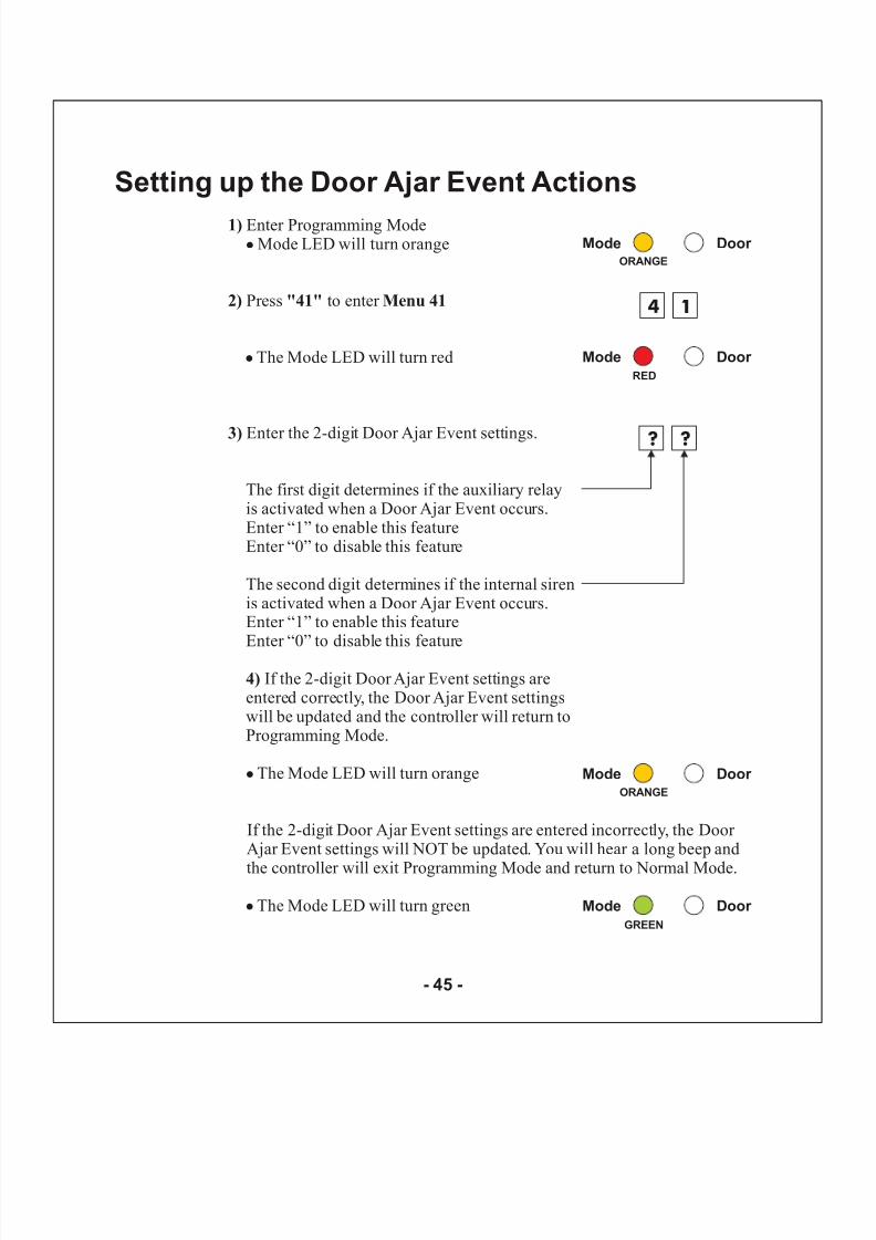
1)
2) "41" Menu 41
3)
4)
Enter Programming ModeMode LED will turn orange
Press to enter
The Mode LED will turn red
Enter the 2-digit Door Ajar Event settings.
The first digit determines if the auxiliary relayis activated when a Door Ajar Event occurs.Enter “1” to enable this featureEnter “0” to disable this feature
The second digit determines if the internal sirenis activated when a Door Ajar Event occurs.Enter “1” to enable this featureEnter “0” to disable this feature
If the 2-digit Door Ajar Event settings areentered correctly, the Door Ajar Event settingswill be updated and the controller will return toProgramming Mode.
The Mode LED will turn orange
If the 2-digit Door Ajar Event settings are entered incorrectly, the Door Ajar Event settings will NOT be updated. You will hear a long beep and
the controller will exit Programming Mode and return to Normal Mode.
The Mode LED will turn green
!
!
!
!
Mode Door ORANGE
Mode Door RED
4 1
Mode Door
GREEN
? ?
Mode Door ORANGE
Setting up the Door Ajar Event Actions
- 45 -

8/6/2019 AC-115 Hardware IM
http://slidepdf.com/reader/full/ac-115-hardware-im 47/58
1)
2) "42" Menu 42
3)
4)
Enter Programming ModeMode LED will turn orange
Press to enter
The Mode LED will turn red
Enter the 2-digit Forced Door Event settings.
The first digit determines if the auxiliary relay isactivated when a Forced Door Event occurs.Enter “1” to enable this featureEnter “0” to disable this feature
The second digit determines if the internal sirenis activated when a Forced Door Event occurs.Enter “1” to enable this featureEnter “0” to disable this feature
If the 2-digit Force Door Event settings are entered correctly, the ForcedDoor Event settings will be updated and the controller will return toProgramming Mode.
The Mode LED will turn orange
If the 2-digit Forced Door Event settings are entered incorrectly, the ForcedDoor Event settings will NOT be updated. You will hear a long beep and thecontroller will exit Programming Mode and return to Normal Mode.
The Mode LED will turn green
!
!
!
!
Mode Door ORANGE
Mode Door RED
4 2
Mode Door GREEN
? ?
Mode Door ORANGE
Setting up the Forced Door Event Actions
- 46 -

8/6/2019 AC-115 Hardware IM
http://slidepdf.com/reader/full/ac-115-hardware-im 48/58
1)
2) "43" Menu 43
3)
4)
Enter Programming ModeMode LED will turn orange
Press to enter
The Mode LED will turn red
Enter the 2-digit Tamper Event settings.
The first digit determines if the auxiliary relayis activated when a Tamper Event occurs.Enter “1” to enable this featureEnter “0” to disable this feature
The second digit determines if the internalsiren is activated when a Tamper Event occurs.Enter “1” to enable this featureEnter “0” to disable this feature
If the 2-digit Tamper Event settings are entered correctly, the Tamper Event settings will be updated and the controller will return toProgramming Mode.
The Mode LED will turn orange
If the 2-digit Tamper Event settings are entered incorrectly, the Tamper Event settings will NOT be updated. You will hear a long beep and thecontroller will exit Programming Mode and return to Normal Mode.
The Mode LED will turn green
!
!
!
!
Mode Door ORANGE
Mode Door RED
4 3
Mode Door GREEN
? ?
Mode Door ORANGE
Setting up the Tamper Event Actions
- 47 -
8/6/2019 AC-115 Hardware IM
http://slidepdf.com/reader/full/ac-115-hardware-im 49/58
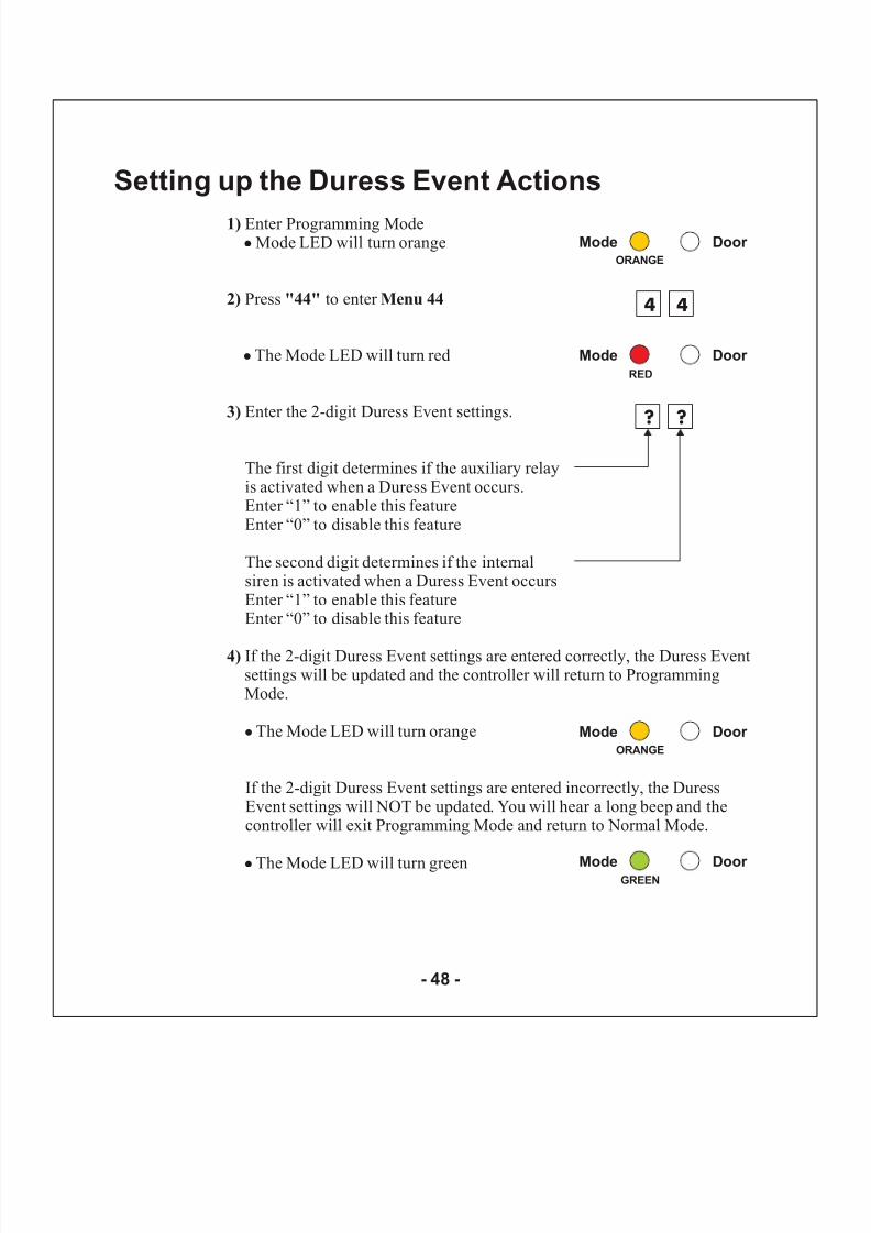
1)
2) "44" Menu 44
3)
4)
Enter Programming ModeMode LED will turn orange
Press to enter
The Mode LED will turn red
Enter the 2-digit Duress Event settings.
The first digit determines if the auxiliary relayis activated when a Duress Event occurs.Enter “1” to enable this featureEnter “0” to disable this feature
The second digit determines if the internalsiren is activated when a Duress Event occursEnter “1” to enable this featureEnter “0” to disable this feature
If the 2-digit Duress Event settings are entered correctly, the Duress Eventsettings will be updated and the controller will return to ProgrammingMode.
The Mode LED will turn orange
If the 2-digit Duress Event settings are entered incorrectly, the DuressEvent settings will NOT be updated. You will hear a long beep and thecontroller will exit Programming Mode and return to Normal Mode.
The Mode LED will turn green
!
!
!
!
Mode Door ORANGE
Mode Door
RED
4 4
Mode Door GREEN
? ?
Mode Door ORANGE
Setting up the Duress Event Actions
- 48 -
8/6/2019 AC-115 Hardware IM
http://slidepdf.com/reader/full/ac-115-hardware-im 50/58
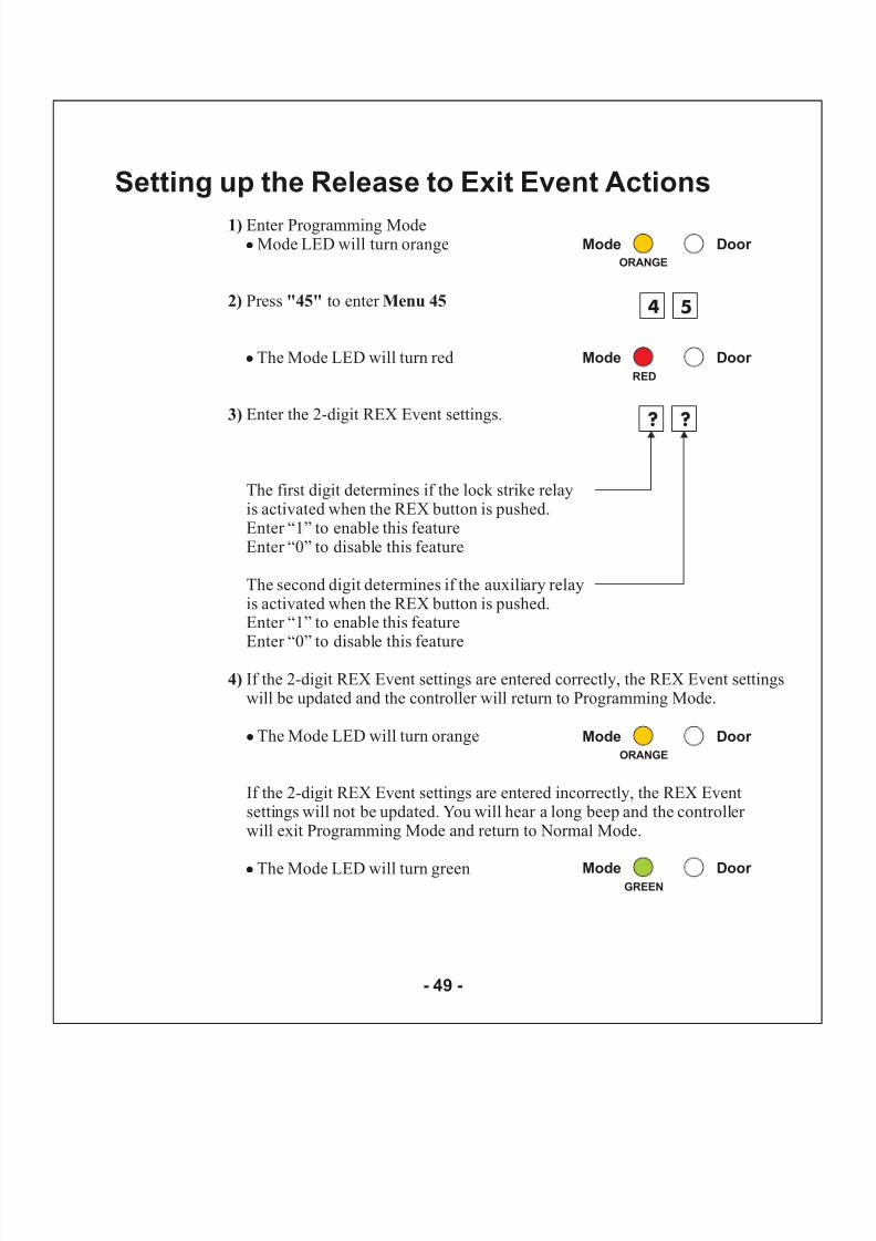
1)
2) "45" Menu 45
3)
4)
Enter Programming ModeMode LED will turn orange
Press to enter
The Mode LED will turn red
Enter the 2-digit REX Event settings.
The first digit determines if the lock strike relayis activated when the REX button is pushed.Enter “1” to enable this featureEnter “0” to disable this feature
The second digit determines if the auxiliary relayis activated when the REX button is pushed.Enter “1” to enable this featureEnter “0” to disable this feature
If the 2-digit REX Event settings are entered correctly, the REX Event settingswill be updated and the controller will return to Programming Mode.
The Mode LED will turn orange
If the 2-digit REX Event settings are entered incorrectly, the REX Eventsettings will not be updated. You will hear a long beep and the controller will exit Programming Mode and return to Normal Mode.
The Mode LED will turn green
!
!
!
!
Mode Door ORANGE
Mode Door RED
4 5
Mode Door GREEN
? ?
Mode Door ORANGE
Setting up the Release to Exit Event Actions
- 49 -
8/6/2019 AC-115 Hardware IM
http://slidepdf.com/reader/full/ac-115-hardware-im 51/58
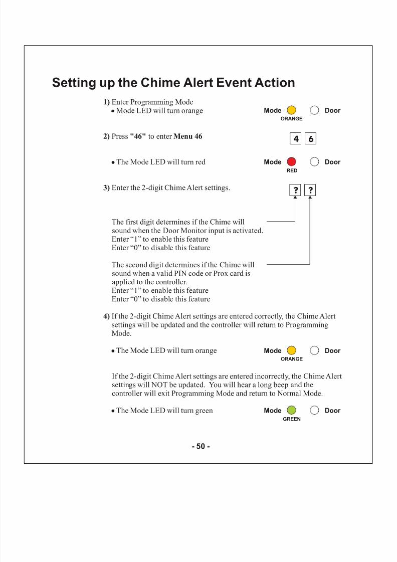
1)
2) "46" Menu 46
3)
4)
Enter Programming ModeMode LED will turn orange
Press to enter
The Mode LED will turn red
Enter the 2-digit Chime Alert settings.
The first digit determines if the Chime willsound when the Door Monitor input is activated.Enter “1” to enable this featureEnter “0” to disable this feature
The second digit determines if the Chime willsound when a valid PIN code or Prox card isapplied to the controller.Enter “1” to enable this featureEnter “0” to disable this feature
If the 2-digit Chime Alert settings are entered correctly, the Chime Alertsettings will be updated and the controller will return to ProgrammingMode.
The Mode LED will turn orange
If the 2-digit Chime Alert settings are entered incorrectly, the Chime Alertsettings will NOT be updated. You will hear a long beep and the
controller will exit Programming Mode and return to Normal Mode.
The Mode LED will turn green
!
!
!
!
Mode Door ORANGE
Mode Door
RED
4 6
Mode Door GREEN
? ?
Mode Door ORANGE
Setting up the Chime Alert Event Action
- 50 -
8/6/2019 AC-115 Hardware IM
http://slidepdf.com/reader/full/ac-115-hardware-im 52/58
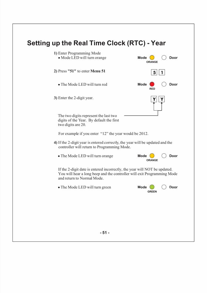
1)
2) "51" Menu 51
3)
4)
Enter Programming ModeMode LED will turn orange
Press to enter
The Mode LED will turn red
Enter the 2-digit year.
The two digits represent the last twodigits of the Year. By default the firsttwo digits are 20.
For example if you enter “12” the year would be 2012.
If the 2-digit year is entered correctly, the year will be updated and thecontroller will return to Programming Mode.
The Mode LED will turn orange
If the 2-digit date is entered incorrectly, the year will NOT be updated.You will hear a long beep and the controller will exit Programming Modeand return to Normal Mode.
The Mode LED will turn green
!
!
!
!
Mode Door ORANGE
Mode Door RED
5 1
Mode Door GREEN
Y Y
Mode Door ORANGE
Setting up the Real Time Clock (RTC) - Year
- 51 -
8/6/2019 AC-115 Hardware IM
http://slidepdf.com/reader/full/ac-115-hardware-im 53/58
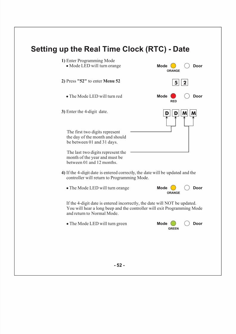
1)
2) "52" Menu 52
3)
4)
Enter Programming ModeMode LED will turn orange
Press to enter
The Mode LED will turn red
Enter the 4-digit date.
The first two digits representthe day of the month and should be between 01 and 31 days.
The last two digits represent themonth of the year and must be between 01 and 12 months.
If the 4-digit date is entered correctly, the date will be updated and thecontroller will return to Programming Mode.
The Mode LED will turn orange
If the 4-digit date is entered incorrectly, the date will NOT be updated.You will hear a long beep and the controller will exit Programming Modeand return to Normal Mode.
The Mode LED will turn green
!
!
!
!
Mode Door ORANGE
Mode Door RED
5 2
Mode Door GREEN
D D M M
Mode Door ORANGE
Setting up the Real Time Clock (RTC) - Date
- 52 -
8/6/2019 AC-115 Hardware IM
http://slidepdf.com/reader/full/ac-115-hardware-im 54/58
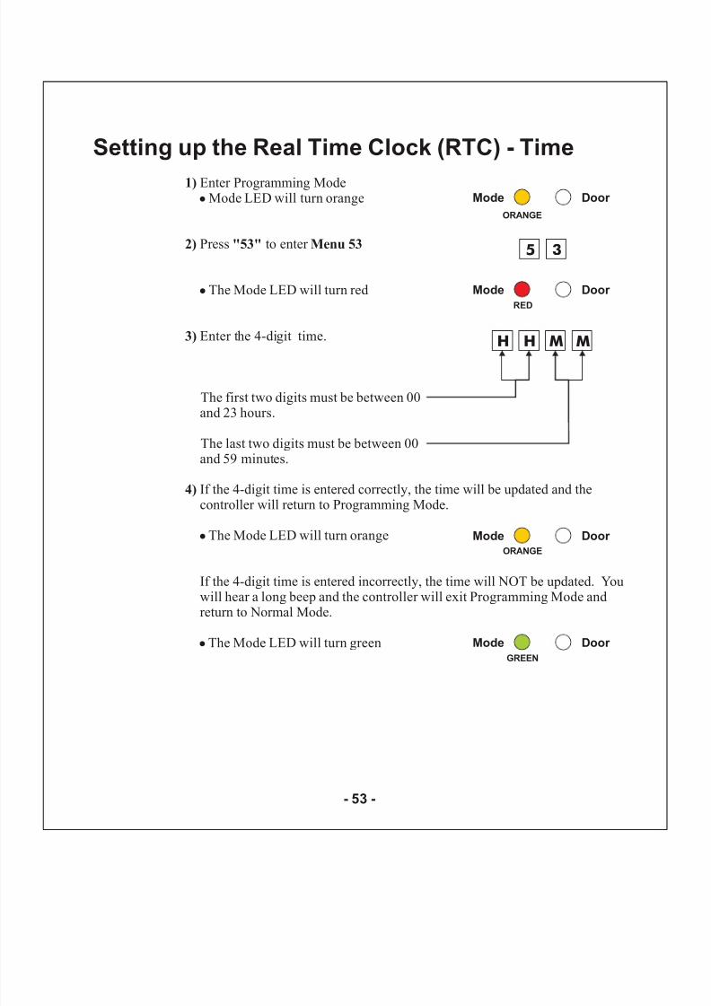
1)
2) "53" Menu 53
3)
4)
Enter Programming ModeMode LED will turn orange
Press to enter
The Mode LED will turn red
Enter the 4-digit time.
The first two digits must be between 00and 23 hours.
The last two digits must be between 00and 59 minutes.
If the 4-digit time is entered correctly, the time will be updated and thecontroller will return to Programming Mode.
The Mode LED will turn orange
If the 4-digit time is entered incorrectly, the time will NOT be updated. Youwill hear a long beep and the controller will exit Programming Mode andreturn to Normal Mode.
The Mode LED will turn green
!
!
!
!
Mode Door
ORANGE
Mode Door
RED
5 3
Mode Door
GREEN
H H M M
Mode Door ORANGE
Setting up the Real Time Clock (RTC) - Time
- 53 -
8/6/2019 AC-115 Hardware IM
http://slidepdf.com/reader/full/ac-115-hardware-im 55/58
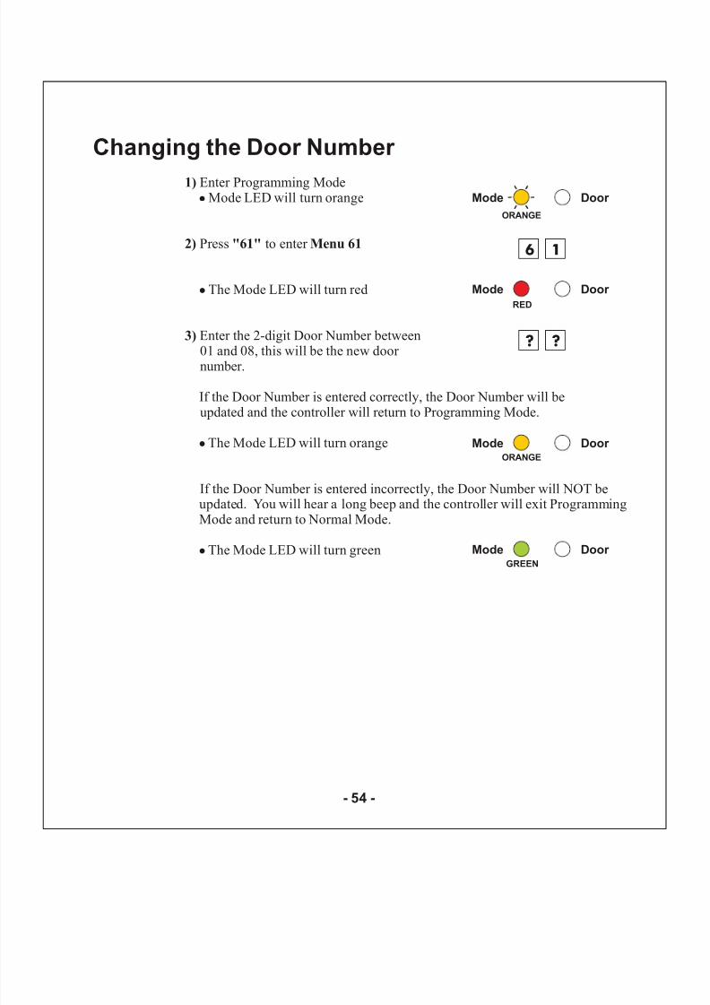
Changing the Door Number
1)
2) "61" Menu 61
3)
Enter Programming ModeMode LED will turn orange
Press to enter
The Mode LED will turn red
Enter the 2-digit Door Number between
01 and 08, this will be the new door number.
If the Door Number is entered correctly, the Door Number will beupdated and the controller will return to Programming Mode.
The Mode LED will turn orange
If the Door Number is entered incorrectly, the Door Number will NOT beupdated. You will hear a long beep and the controller will exit ProgrammingMode and return to Normal Mode.
The Mode LED will turn green
!
!
!
!
Mode Door
ORANGE
Mode Door
RED
6 1
? ?
Mode Door ORANGE
Mode Door GREEN
- 54 -
8/6/2019 AC-115 Hardware IM
http://slidepdf.com/reader/full/ac-115-hardware-im 56/58
Appendix AA
In the event that your Programming Code is lost, complete the following procedure to enter Programming Mode so that you may create a newProgramming Code.
The AC-115 must be in Normal Mode otherwise this will not work.
Make sure that the Mode LED is green before proceeding.
1)
2)
3)
4)
5)
6)
Remove power from the AC-115
Press the REX button
Apply power to the unit with the REX button pressed
Release the REX button
You now have 60 seconds to program an new Programming Code into thecontroller using the initial default code 1234, before the controller reverts tothe existing code.
Enter Programming Mode using the default Programming Code 1234
Use menu “21” to set a new Programming Code
Replacing a lost Programming Code
- 55 -
8/6/2019 AC-115 Hardware IM
http://slidepdf.com/reader/full/ac-115-hardware-im 57/58
Appendix BB
In the event that your Normal / Secure Code is lost and you are locked in SecureMode, complete the following procedure to re-enter Normal Mode so that youmay program a new Normal / Secure Code.
The AC-115 must be in Secure Mode otherwise this will not work.
Make sure that the Mode LED is red before proceeding.
1)
2)
3)
4)
Remove power from the AC-115
Press the REX button
Apply power to the unit with the REX button pressed
Release the REX button
You now have 60 seconds to enter the default Secure Code 3838 to re-enter into Normal Mode.
Once in Normal Mode you have the ability to enter Programming Mode andcreate a new Secure Code. See “Menu 22” to set a new Normal / Secure Code.
Replacing a lost Normal / Secure Code
- 56 -

8/6/2019 AC-115 Hardware IM
http://slidepdf.com/reader/full/ac-115-hardware-im 58/58
Technical Support
http:///www.rosslare.com.hk/support/
Rosslare Enterprises Ltd.905-912 Wing Fat Industrial Bldg.,12 Wang Tai Road, Kowloon Bay,Hong Kong.
Tel: (852) 2795 5630Fax: (852) 2795 1508E-mail: [email protected]
Rosslare Security Products S.r.lVia F.lli Gabba 5, 20121 Milano, Italy
Tel: (39) 0382 24800Fax: (39) 0382 24800E-mail: [email protected]
Rosslare NAPDC200 East Howard Street, Suite 238,Des Plaines, IL 60018USA
Tel: (847) 827 6330Fax: (847) 827 6433
E-mail: [email protected]
International Web Site:
Asia, Australia, & South America
Europe, Russia, Middle East, Africa
United States and Canada
:
:
: