
A n ode s Ov e r l aye r towar d H i g h l y R e v e r s i ...
21
Page 1/21 Interfacial Manipulation via In-Situ Grown ZnSe Overlayer toward Highly Reversible Zn Metal Anodes Xianzhong Yang Soochow University Chao Li Shandong University of Technology Zhongti Sun Soochow University Shuai Yang State Key Laboratory of Low Dimensional Quantum Physics, Department of Physics, Tsinghua University Zixiong Shi Soochow University Rong Huang Soochow University Bingzhi Liu Soochow University Shuo Li Soochow University Yuhan Wu Soochow University Menglei Wang Soochow University Yiwen Su Soochow University Shi Xue Dou University of Wollongong https://orcid.org/0000-0003-3824-7693 Jingyu Sun ( [email protected] ) Soochow University Article Keywords: Zn metal anode, Energy storage, Batteries, energy and catalysis
Transcript of A n ode s Ov e r l aye r towar d H i g h l y R e v e r s i ...

Page 1/21
Interfacial Manipulation via In-Situ Grown ZnSeOverlayer toward Highly Reversible Zn MetalAnodesXianzhong Yang
Soochow UniversityChao Li
Shandong University of TechnologyZhongti Sun
Soochow UniversityShuai Yang
State Key Laboratory of Low Dimensional Quantum Physics, Department of Physics, TsinghuaUniversityZixiong Shi
Soochow UniversityRong Huang
Soochow UniversityBingzhi Liu
Soochow UniversityShuo Li
Soochow UniversityYuhan Wu
Soochow UniversityMenglei Wang
Soochow UniversityYiwen Su
Soochow UniversityShi Xue Dou
University of Wollongong https://orcid.org/0000-0003-3824-7693Jingyu Sun ( [email protected] )
Soochow University
Article
Keywords: Zn metal anode, Energy storage, Batteries, energy and catalysis

Page 2/21
Posted Date: April 20th, 2021
DOI: https://doi.org/10.21203/rs.3.rs-400312/v1
License: This work is licensed under a Creative Commons Attribution 4.0 International License. Read Full License
Page 3/21
AbstractZn metal anode has garnered growing scienti�c and industrial interest owing to its appropriate redoxpotential, low cost and good safety. Nevertheless, the instability of Zn metal, caused by dendriteformation, hydrogen evolution and side reactions, gives rise to poor electrochemical stability andunsatisfactory cycling life, greatly hampering large-scale utilization. Herein, an in-situ grown ZnSe layerwith controllable thickness is crafted over one side of commercial Zn foil via chemical vapor deposition,aiming to achieve optimized interfacial manipulation between aqueous electrolyte/Zn anode. Thus-derived ZnSe overlayer not only prevents water penetration and restricts Zn2+ two-dimensional diffusion,but also homogenizes the electric �eld at the interface and facilitates favorable (002) plane growth of Zn.As a result, dendrite-free and homogeneous Zn deposition is obtained; side reactions are concurrentlyinhibited. In consequence, a high Coulombic e�ciency of 99.2% and high cyclic stability for 860 cycles at1.0 mA cm–2 in symmetrical cells is harvested. Meanwhile, when paired with V2O5 cathode, assembled
full cell achieves an outstanding initial capacity (200 mAh g–1) and elongated lifespan (a capacityretention of 84% after 1000 cycles) at 5.0 A g–1. Our highly reversible Zn anode enabled by the interfacialmanipulation strategy is anticipated to satisfy the demand of industrial and commercial use.
IntroductionRecent years have witnessed a burgeoning development of advanced energy storage systems to meet theurgent energy demand in individual and industrial applications. In this sense, aqueous rechargeablebatteries have stimulated increased attentions due to their intrinsic safety and environmental benignity,as compared to their counterparts with �ammable organic electrolytes1–4. The high ionic conductivity ofaqueous electrolyte in addition endows the corresponding devices with excellent rate performance andfast reaction kinetics. To capitalize on these merits, aqueous Zn-ion batteries (AZIBs) coupled withaffordable and nontoxic features are worthy of in-depth investigation. More encouragingly, Zn metal is anappealing anode candidate on the ground of outstanding volumetric speci�c capacity (5855 mAh cm− 3)and appropriate redox potential (− 0.76 V vs. standard hydrogen electrode)5, 6. Nevertheless, thecommercial Zn foil anode is far from ideal to realize reversible dissolution/deposition duringelectrochemical cycling (Scheme 1a). This is primarily owing to the fact that the surface protuberance ishighly likely to trigger an intense cusp effect, in turn resulting in the uneven deposition of Zn and radicalformation of dendrites7, 8. Thus-grown dendrites could ultimately pierce the separator and induce short-circuit failure of the battery9. Meanwhile, problematic issues including hydrogen evolution10 and sidereactions11 remain urgent to be solved since they are main origins of catastrophic volume expansion,electrode corrosion and surface passivation. Therefore, it is of vital importance to develop effectiveavenues to protect Zn anode from these caveats toward the realization of high-performance AZIBdevices.
In response, strategic efforts have been devoted to tackle aforementioned bottlenecks in pursuit ofachieving highly reversible Zn anodes2, which mainly encompass electrolyte modulation12–14, host

Page 4/21
design15 and interface engineering16. Firstly, the composition and concentration of electrolytes exert asigni�cant impact on the Zn stripping/plating behaviors. For instance, the innovative “water in salt”electrolyte (1 M Zn(TFSI)2 and 20 M LiTFSI) can effectively restrain Zn dendrite and suppress hydrogen
evolution throughout forming a new solvation sheath13. Secondly, zincophilic host design allows thedictation of the Zn/host interface to harvest a low Zn nucleation barrier15 or facilitate a heteroepitaxial Znnucleation17, accordingly enabling the inhibition of the dendrite growth. Last but not the least,Zn/electrolyte interface engineering has been extensively explored due to its direct in�uence over Znnucleation and growth. This can be implemented by introducing arti�cial protective layer comprisingconductive or non-conductive coatings11. The conductive coatings, such as graphene4, MXene16, In18,Au19 and Cu20, are bene�cial to guiding a homogeneous Zn deposition to eliminate the dendrite. Inparallel, the non-conductive shields, including TiO2
21, 22, CaCO323, ZnO24, ZrO2
25, ZnS26 and kaolin27,would deactivate the dendritic formation via decreasing the nucleation energy barrier and inhibithydrogen evolution by protecting the active Zn from the direct attack of the bulk electrolyte. Despitepromising protection effects achieved on the anode side, it is worth noting that these prevailing strategiesrely heavily upon ex-situ coating of foreign layers over Zn foils, which normally leads to non-uniform �lmswith uncontrolled thickness uniformity and limited production scalability. In turn, the high-rate cyclabilitycould be disabled and the energy density of entire device might be undermined. This would ultimatelyspur us to develop a simple yet effective method to precisely regulate the anode/electrolyte interfacetoward stabilized Zn anode.
Herein, we devise a highly reversible Zn anode realized by in-situ grown Zn selenide (ZnSe) overlayer viachemical vapor deposition (CVD) (Scheme 1b), accomplishing e�cient interface manipulation in amanner analogous to the arti�cial solid electrolyte interphase (SEI) for alkali metal anode protection28.Our designing strategy harnessing su�cient scalability and intrinsic simplicity holds the potential toadequately meet practical demands. The initially disordered Zn protuberances are converted to ZnSenanoparticles upon selenization, where ultrathin ZnSe layer is accordingly produced and uniformly boundto Zn metal to form a vertically aligned heterostructure (ZnSe@Zn). Such an interface engineering cansimultaneously lower the Zn nucleation overpotential and homogenize the local current density to a greatextent. The favorable zincophilicity of ZnSe would help restrict the two-dimensional diffusion of Zn ionsalong the interface. As a result, the growth of Zn dendrite is effectively inhibited. In addition, the in-situformed ZnSe overlayer enables to decline the de-solvation energy barrier of hydrated-Zn, thereby boostingZn2+ transfer kinetics and deactivating hydrogen evolution. Bene�ting from our interfacial manipulation,thus-derived ZnSe@Zn anode features an elongated lifespan of 860 h at a current density of 1.0 mA cm−
2. It can even sustain a stable stripping/plating operation at 10 mA cm− 2 for as long as 260 h. Moreimpressively, the full cell based on ZnSe@Zn anode harvests a capacity retention of 84% after 1000cycles at 5.0 A g− 1. Our highly reversible Zn anode enabled by the interfacial manipulation strategy isanticipated to satisfy the demand of industrial and commercial use.
Results

Page 5/21
Synthesis and characterization of ZnSe overlayer.
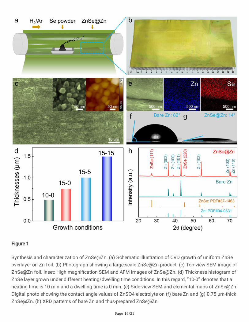
Fig. 1a schematically depicts the synthetic set-up for the in-situ growth of ZnSe overlayer on commercialZn foil by CVD. The Zn foil serving as the growth substrate is placed at the downstream of the Ar/H2 gas�ow, which assists to carry the sublimed Se powders coming from the upstream (See Methods). Thisambient-pressure process is facile, simple, economical and potentially scalable. It also bypasses thelengthy high-temperature annealing and tedious vacuum operations. The size of the product, ZnSe@Zn,is merely limited by the furnace dimension. Fig. 1b presents a digital photograph of a 20 cm × 10 cmsized ZnSe@Zn foil with perfect �lm homogeneity produced in a 4-inch tube furnace, demonstrating theviability of large-scale synthesis toward practical applications. The surface morphology of ZnSeoverlayer was examined by scanning electron microscopy (SEM) and atomic force microscopy (AFM). Asshown in Fig. 1c, the full coverage of ZnSe layer upon CVD reaction is helpful to even out a plethora ofsharp protuberances on bare Zn surface (Supplementary Fig. 1). Close-up view further suggests that thus-grown ZnSe exists in the form of nanoparticles with diameters of 30-50 nm (Fig. 1c inset; SupplementaryFig. 2). Such a three-dimensional porous texture would be bene�cial to Zn2+ transport. Notably, thethickness of ZnSe overlayer can be simply dictated by controlling the CVD synthetic parameters, i.e.,altering the temperature ramping rate and dwelling duration (Fig. 1d; Supplementary Fig. 3). Fig. 1epresents a side-view SEM image of ZnSe overlayer (affording a thickness of 0.75 μm), wherecorresponding elemental maps manifest uniform distribution of detected elements.
The wettability to electrolyte is one of the key factors for reversible Zn stripping/plating as it exertsin�uence upon interfacial ion-transfer resistance8. In this respect, bare Zn foil possesses a fairly poorwettability by 2 M ZnSO4 electrolyte, displaying a contact angle of 82° based on static contact anglemeasurement (Fig. 1f). In contrast, the contact angle sharply declines to 14° on ZnSe@Zn foil (ZnSethickness: 0.75 μm), implying markedly enhanced wettability (Fig. 1g). The contact angle values in thecase of ZnSe@Zn foil with different ZnSe thickness are further compared (Supplementary Fig. 4),amongst which the 0.75 μm-thick ZnSe harvests the smallest contact angle. Collected XRD patterns ofZnSe@Zn and bare Zn indicate that the ZnSe grows primarily along (111) direction (Fig. 1h;Supplementary Fig. 5)29. Recognizable Raman signals further verify the successful preparation of ZnSeoverlayer (Supplementary Fig. 6).
Electrochemical performance of ZnSe@Zn
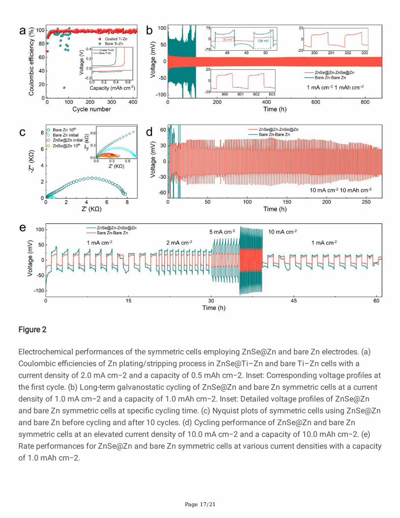
To evaluate the plating/stripping reversibility and Zn utilization of Zn anode with/without ZnSeprotection, Coulombic e�ciency (CE) measurements were carried out in two-electrode cells (ZnSe@Ti–Znand Ti–Zn) with a �xed capacity of 0.5 mAh cm−2 at a current density of 2.0 mA cm−2. The ZnSe coatingon Ti foil was obtained by CVD to derive the ZnSe@Ti electrode (Supplementary Fig. 7). In terms of thegalvanostatic cycling performance, ZnSe@Ti–Zn cell presents an initial plating-stripping voltagehysteresis of 87 mV, which is obviously lower than that (133 mV) of bare Ti–Zn cell (Fig. 2a inset;Supplementary Fig. 8). Encouragingly, ZnSe@Ti–Zn cell could maintain 400 cycles with an average CE of99.2%, indicating favorable reversibility and excellent durability (Fig. 2a). In stark contrast, bare Ti–Zn cell
Page 6/21
merely sustains for 50 cycles with drastic �uctuations of CE values, suggesting the presence of sidereactions and dendrite growth. It is safe to conclude that the ZnSe overlayer would well manipulate thenucleation and growth of Zn toward a highly reversible anode.
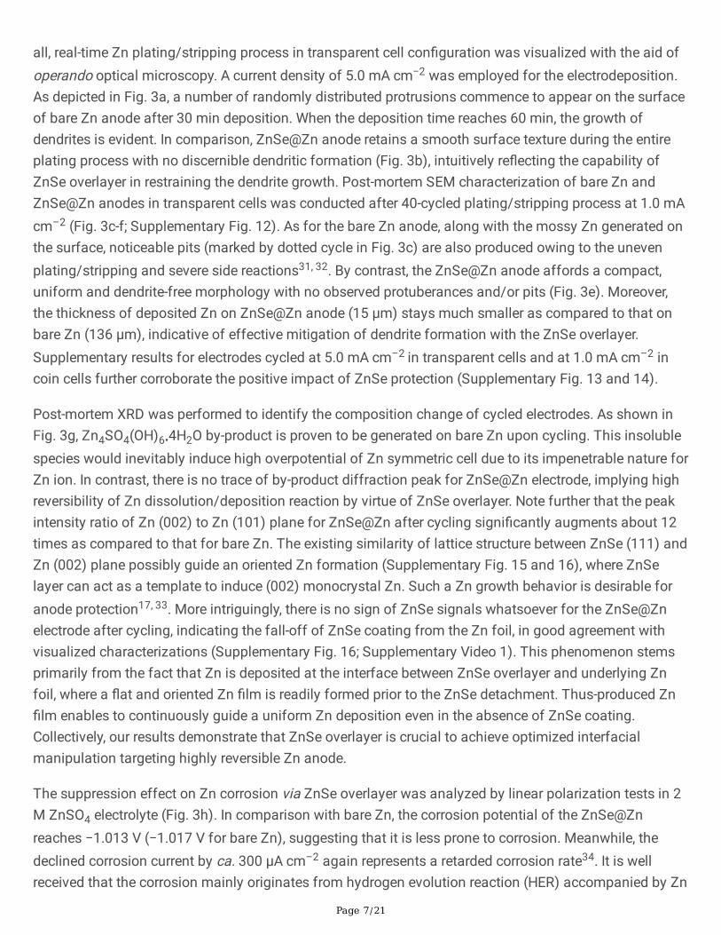
To verify the advanced effect of anode protection via in-situ formed ZnSe overlayer, galvanostatic cyclicstability of symmetric cells was evaluated under various current densities and areal capacities. Fig. 2bshows the long-term cycling performance of bare Zn and ZnSe@Zn symmetric cells at 1.0 mA cm−2 witha capacity of 1.0 mAh cm−2. Upon cycling for ~80 h, a sudden and irreversible voltage rise occurs for bareZn cell, which could be attributed to the accumulation of adverse “dead Zn” and by-products. Thepresence of these species is detrimental throughout occluding ion transport pathways, resulting in a largevoltage hysteresis of 128 mV. In contrast, ZnSe@Zn symmetric cell readily displays a far more stablevoltage pro�le with much declined voltage hysteresis of 30 mV that sustains more than 860 h,approximately 10 times longer in comparison with bare Zn cell. Note that our CVD route is versatileenough to enable the delicate control over the thickness of ZnSe layer, where an optimized thickness at0.75 μm could be gained in response to generating the smallest polarization (Supplementary Fig. 9). Thisresult echoes well with the observation from electrolyte wettability tests. The re�nement ofelectrolyte/ZnSe@Zn interface, which expedites the electrokinetics of Zn deposition, can further becon�rmed throughout electrochemical impedance spectroscopy (EIS) analysis. As disclosed in theNyquist plots in Fig. 2c, the impedance of the bare Zn cell manifests a remarkable increase (from 0.7 to7.7 kΩ) after 10 cycles, whereas the impedance of the ZnSe@Zn cell shows a slight decrease from 0.4 to0.25 kΩ, revealing that the ZnSe overlayer is competent in declining charge transfer resistance in aqueousZnSO4 electrolyte. According to Sand’s model30, the formation time of dendrite is inversely proportional tocurrent density. In addition, the interfacial electric �eld becomes rather uneven under elevated currentdensities, inducing less yet adverse nucleation sites. Areal speci�c capacity is also a nontrivial factor,where a higher one would augment the dendrite size. Therefore, Zn plating/stripping behavior quicklydeteriorates under high current densities/capacities due to rampant dendrite formation7. Impressively, theZnSe@Zn cell still remains highly stable for more than 250 h even under the high currentdensity/capacity at 10.0 mA cm−2/10.0 mAh cm−2 (Fig. 2d; Supplementary Fig. 10), representing one ofthe best performances achieved by far in such stringent conditions (Supplementary Table 1). Fig. 2edisplays the rate performances of symmetric cells with a �xed capacity of 1.0 mAh cm−2 under variedcurrent densities from 1.0 to 10.0 mA cm−2. Apparently, ZnSe@Zn cell harvests a much lower voltagehysteresis at all current densities in comparison with bare Zn counterpart, demonstrating superiorstability and high reversibility. In addition, dramatic reduction of nucleation overpotential tested undervarious conditions was witnessed upon the introduction of ZnSe overlayer (Supplementary Fig. 11),which is conducive to uniform deposition of Zn.
Mechanism analysis on ZnSe protection effect
To probe the electrochemical protection mechanism of ZnSe overlayer in ZnSO4 electrolyte system, in-situ/ex-situ scrutinization in combination with electroanalytic characterization were carried out. First of
Page 7/21
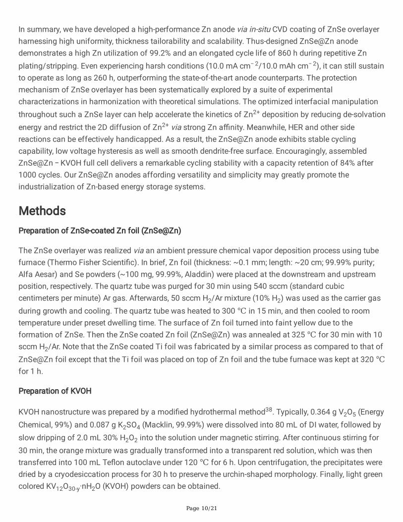
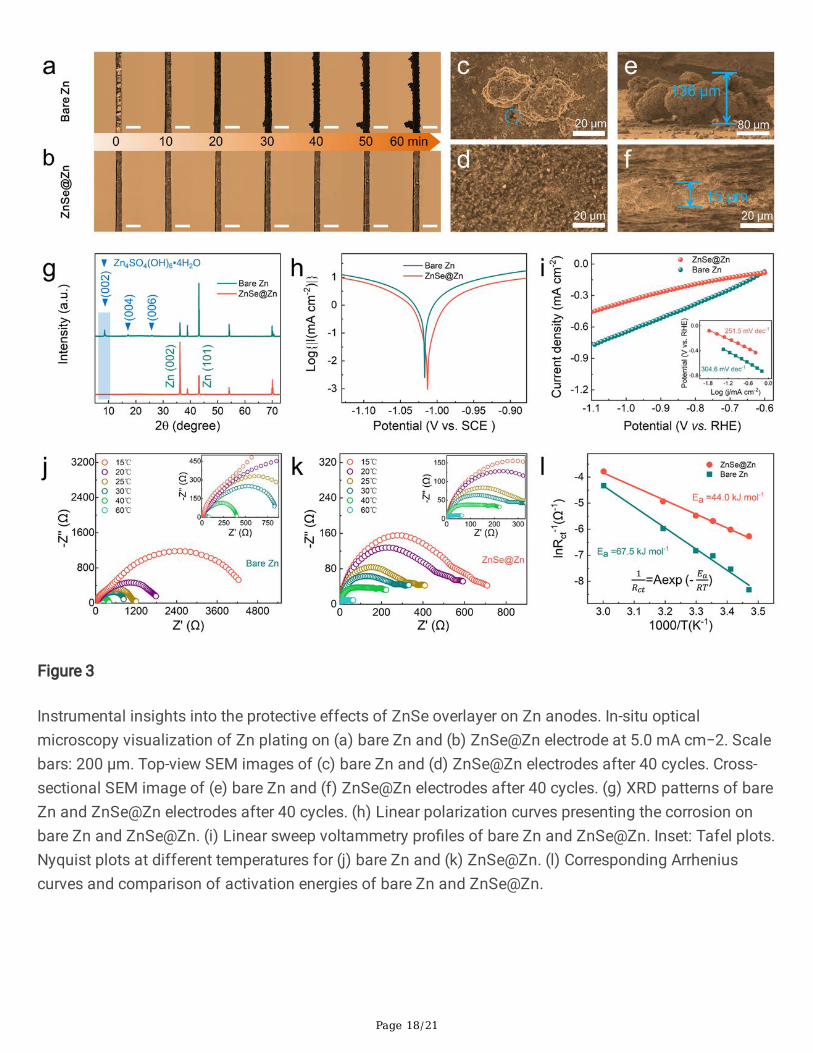
all, real-time Zn plating/stripping process in transparent cell con�guration was visualized with the aid ofoperando optical microscopy. A current density of 5.0 mA cm−2 was employed for the electrodeposition.As depicted in Fig. 3a, a number of randomly distributed protrusions commence to appear on the surfaceof bare Zn anode after 30 min deposition. When the deposition time reaches 60 min, the growth ofdendrites is evident. In comparison, ZnSe@Zn anode retains a smooth surface texture during the entireplating process with no discernible dendritic formation (Fig. 3b), intuitively re�ecting the capability ofZnSe overlayer in restraining the dendrite growth. Post-mortem SEM characterization of bare Zn andZnSe@Zn anodes in transparent cells was conducted after 40-cycled plating/stripping process at 1.0 mAcm–2 (Fig. 3c-f; Supplementary Fig. 12). As for the bare Zn anode, along with the mossy Zn generated onthe surface, noticeable pits (marked by dotted cycle in Fig. 3c) are also produced owing to the unevenplating/stripping and severe side reactions31, 32. By contrast, the ZnSe@Zn anode affords a compact,uniform and dendrite-free morphology with no observed protuberances and/or pits (Fig. 3e). Moreover,the thickness of deposited Zn on ZnSe@Zn anode (15 μm) stays much smaller as compared to that onbare Zn (136 μm), indicative of effective mitigation of dendrite formation with the ZnSe overlayer.Supplementary results for electrodes cycled at 5.0 mA cm–2 in transparent cells and at 1.0 mA cm–2 incoin cells further corroborate the positive impact of ZnSe protection (Supplementary Fig. 13 and 14).
Post-mortem XRD was performed to identify the composition change of cycled electrodes. As shown inFig. 3g, Zn4SO4(OH)6•4H2O by-product is proven to be generated on bare Zn upon cycling. This insolublespecies would inevitably induce high overpotential of Zn symmetric cell due to its impenetrable nature forZn ion. In contrast, there is no trace of by-product diffraction peak for ZnSe@Zn electrode, implying highreversibility of Zn dissolution/deposition reaction by virtue of ZnSe overlayer. Note further that the peakintensity ratio of Zn (002) to Zn (101) plane for ZnSe@Zn after cycling signi�cantly augments about 12times as compared to that for bare Zn. The existing similarity of lattice structure between ZnSe (111) andZn (002) plane possibly guide an oriented Zn formation (Supplementary Fig. 15 and 16), where ZnSelayer can act as a template to induce (002) monocrystal Zn. Such a Zn growth behavior is desirable foranode protection17, 33. More intriguingly, there is no sign of ZnSe signals whatsoever for the ZnSe@Znelectrode after cycling, indicating the fall-off of ZnSe coating from the Zn foil, in good agreement withvisualized characterizations (Supplementary Fig. 16; Supplementary Video 1). This phenomenon stemsprimarily from the fact that Zn is deposited at the interface between ZnSe overlayer and underlying Znfoil, where a �at and oriented Zn �lm is readily formed prior to the ZnSe detachment. Thus-produced Zn�lm enables to continuously guide a uniform Zn deposition even in the absence of ZnSe coating.Collectively, our results demonstrate that ZnSe overlayer is crucial to achieve optimized interfacialmanipulation targeting highly reversible Zn anode.
The suppression effect on Zn corrosion via ZnSe overlayer was analyzed by linear polarization tests in 2M ZnSO4 electrolyte (Fig. 3h). In comparison with bare Zn, the corrosion potential of the ZnSe@Znreaches −1.013 V (−1.017 V for bare Zn), suggesting that it is less prone to corrosion. Meanwhile, thedeclined corrosion current by ca. 300 μA cm–2 again represents a retarded corrosion rate34. It is wellreceived that the corrosion mainly originates from hydrogen evolution reaction (HER) accompanied by Zn

Page 8/21
dissolution/deposition reaction in weakly acidic ZnSO4 electrolyte11. Along this line, HER activity was
additionally evaluated by linear sweep voltammetry (LSV) measurements24. As displayed in Fig. 3i, it isstriking to �nd that ZnSe@Zn electrode harvests a depressed HER capability as compared to that of bareZn electrode.
The solvation of Zn2+ is a major obstacle for circumventing rapid transport of Zn ions throughout theinterface between electrolyte and Zn anode24, 35. The activation energy (Ea), which represents the energy
required for de-solvation36, can be quantitatively derived using the Arrhenius equation: 1/Rct =Aexp(−Ea/RT), where Rct is the charge transfer resistance and R is the ideal gas constant. Herein, Rct
(Supplementary Table 2) was �tted based on the variable-temperature EIS curves of Zn-Zn and ZnSe@Zn-ZnSe@Zn symmetric cells from 15 to 60 ℃ (Fig. 3j-k). It is evident that all Rct values of ZnSe@Zn cell(Fig. 3k) are much lower than those of bare Zn cell (Fig. 3j). Accordingly, Ea of ZnSe@Zn can be
calculated to be ~44.0 kJ mol−1 (Fig. 3l), in contrast to that of bare Zn cell (~67.5 kJ mol−1). This resultimplies the superior kinetics of Zn2+ transfer throughout the interface between electrolyte and anode.
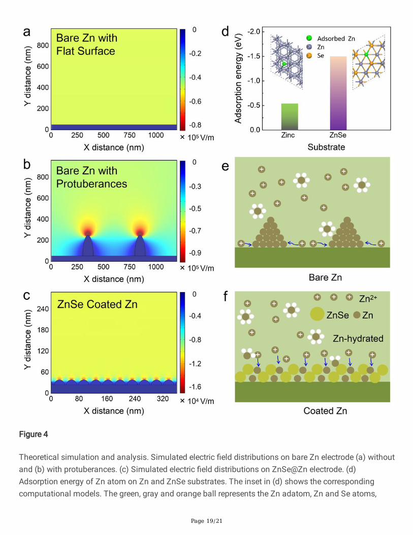
The nucleation and deposition of Zn relies heavily upon the electric �eld distributions at theanode/electrolyte interface7, 16. To investigate the role of in-situ grown ZnSe overlayer played inregulating interfacial electric �eld, �nite element method carried out by COMSOL Multiphysics wasemployed. As depicted in Fig. 4a, the electric �eld distribution is homogeneous on bare Zn anodeharnessing an ideally smooth surface. Nevertheless, the presence of micro-protrusions would strengthenthe surrounding �eld intensity, which is expected to guide uneven deposition of Zn and lead to thedendrite formation (Fig. 4b). Encouragingly, these protuberances could be well eliminated by in-situselenation process. In response, the peak value of �eld intensity sharply decreases from 2.2×10⁵ to1.6×104 V m−1 with the aid of ZnSe overlayer (Fig. 4c). Such a textured ZnSe coating further helpshomogenize the electric �eld on Zn surface, followed by building up uniform charge �ux.
Theoretical simulation based on density functional theory (DFT) route was performed to gain insight intothe interaction between Zn and ZnSe. The calculated adsorption energy of a Zn atom on ZnSe support isapparently higher than that on bare Zn support (Fig. 4d; Supplementary Fig. 17). The strong a�nity of Znwith ZnSe would be of bene�t to suppressing two-dimensional (2D) diffusion of Zn ions.Chronoamperometry was accordingly employed to probe the Zn2+ diffusion dynamics at theanode/electrolyte interface (Supplementary Fig. 18). The current density of bare Zn symmetric cellcontinues to increase beyond 140 s under 150 mV, implying a violent 2D diffusion process. In turn, Zn2+
and hydrated Zn2+ ions tend to aggregate and grow into dendrites to minimize the surface energy (Fig.4e). As for the ZnSe@Zn electrode, the 2D diffusion only occurs within the initial 20 s, after which astable three-dimensional (3D) diffusion pattern becomes predominant. As illustrated in Fig. 4f, adesolvation process proceeds rapidly for hydrated Zn2+ ions upon their arrival at the ZnSe layer owing tolow activation energy. Bene�ting from a favorable 3D diffusion, Zn2+ could then pass through the ZnSelayer rapidly under the potential gradient resulting from the high electron resistance of ZnSe37

Page 9/21
(Supplementary Fig. 19). This fast 3D diffusion process was con�rmed by the high ionic conductivity ofZnSe layer reaching ~1.7 × 10⁻⁵ S cm–1 (Supplementary Fig. 20). Finally, these Zn ions are reduced toZn0 and start to grow along (002) plane on Zn metallic surface.
Electrochemical performance of AZIB full cells
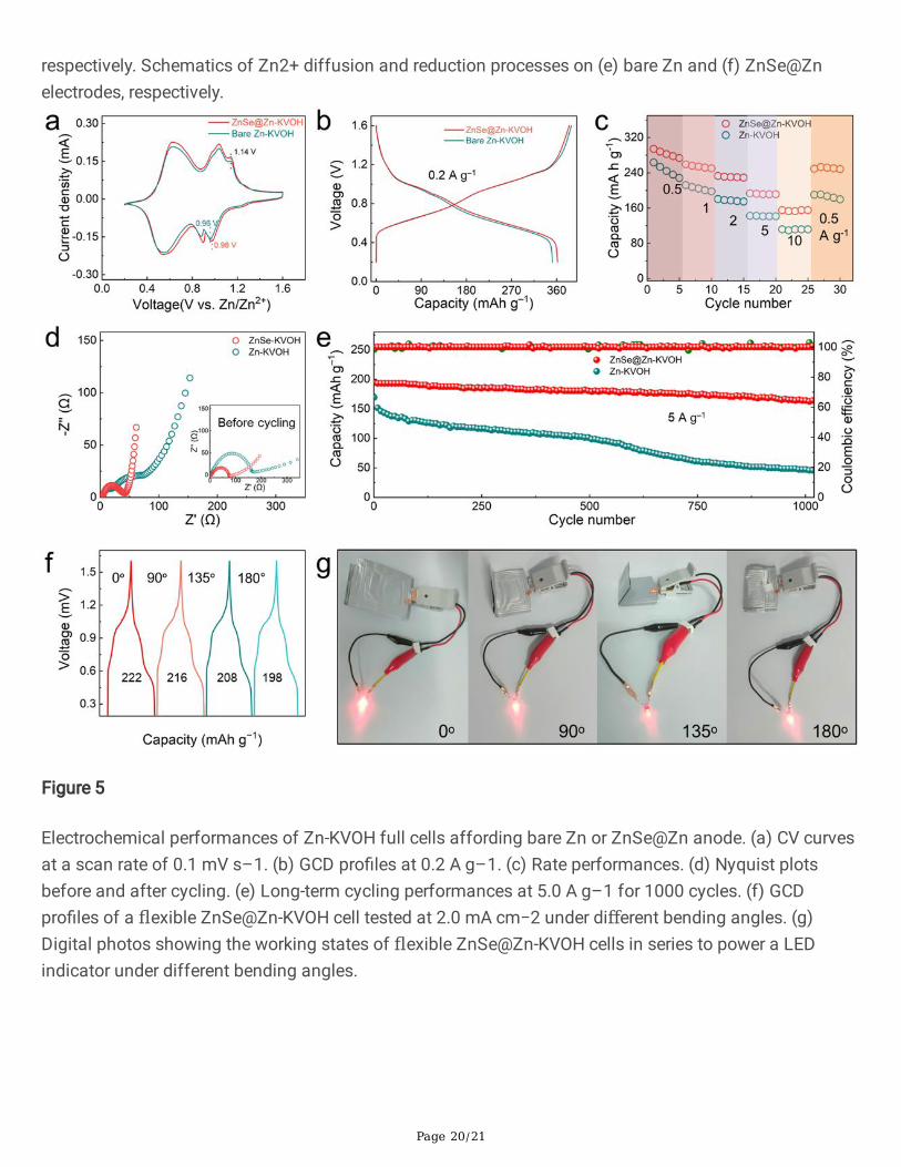
To demonstrate the feasibility of thus-designed ZnSe@Zn anode in practical devices, AZIB full cellscomprising KV12O30-y·nH2O (KVOH)38 cathode (see methods) and ZnSe@Zn anode were assembledemploying 2 M ZnSO4 electrolyte (Supplementary Fig. 21). Fig. 5a records the CV pro�les of
ZnSe@Zn−KVOH and bare Zn−KVOH cells at a scan rate of 0.1 mV s–1 in a voltage window between 0.2and 1.6 V. Both cells manifest two main pairs of redox signals corresponding to two-step redox reactionsof V3+/V4+ and V4+/V5+. The higher current response of full cell with ZnSe@Zn anode as compared tobare Zn anode implies a higher capacity value, which can be con�rmed by galvanostaticcharge/discharge (GCD) curves in Fig. 5b. Fig. 5c draws a comparison of rate performances of both cells.As expected, ZnSe@Zn−KVOH harvests a capacity of 294.2, 259.2, 232.9, 193.4 and 155.1 mAh g−1 at0.5, 1.0, 2.0, 5.0 and 10.0 A g−1, respectively. When the current density returns to 0.5 A g–1, the device stillretains a capacity of 253.1 mAh g–1. This readily outperforms the bare Zn−KVOH cell under identicalconditions. Such outstanding reversibility and rate capability could be attributed to the inhibition ofdendrite formation/side reactions and the maintenance of a homogeneous interface via the versatileZnSe coating, which functions as a high-performance arti�cial SEI layer. Nyquist plots before and aftercycling also reveal that the ZnSe@Zn−KVOH cell exhibits lower charge-transfer resistance and promotedion diffusion kinetics in comparison with the Zn−KVOH counterpart (Fig. 5d). The long-term cyclicstability of both cells was further evaluated (Fig. 5e). As for ZnSe@Zn−KVOH full cell, it manages todeliver an initial capacity of 194.5 mAh g−1 and stabilizes at 163.9 mAh g−1 after 1000 cycles with aretention rate of 84% at 5.0 A g−1. In contrast, the capacity of bare Zn−KVOH cell sharply drops to 47.2mAh g−1 after 1000 cycles.
More impressively, ZnSe@Zn anode harnessing mechanical robustness and large-scale availabilityenlists the construction of flexible AZIB full cells (see methods) toward practical applications(Supplementary Fig. 22). Fig. 5f presents the GCD pro�les of assembled flexible AZIB at 2.0 mA cm−2
under various bending angles of 0°, 90°, 135°, and 180°. Notably, 97.8% of the initial capacity could beretained upon bending at 180°, showing excellent mechanical flexibility. As a proof-of-conceptdemonstration, Fig. 5g displays digital photos of the working states of two �exible AZIBs in tandemcon�guration, enabling to continuously powering a light emitting diode (LED) indicator under differentbending angles, showing its application prospect in wearable electronics. Taken together, these resultscorroborate that the ZnSe overlayers can effectively inhibit the parasitic reactions at the anode/electrolyteinterface and guide uniform Zn deposition in favor of advanced stability of AZIB.
Discussion
Page 10/21
In summary, we have developed a high-performance Zn anode via in-situ CVD coating of ZnSe overlayerharnessing high uniformity, thickness tailorability and scalability. Thus-designed ZnSe@Zn anodedemonstrates a high Zn utilization of 99.2% and an elongated cycle life of 860 h during repetitive Znplating/stripping. Even experiencing harsh conditions (10.0 mA cm− 2/10.0 mAh cm− 2), it can still sustainto operate as long as 260 h, outperforming the state-of-the-art anode counterparts. The protectionmechanism of ZnSe overlayer has been systematically explored by a suite of experimentalcharacterizations in harmonization with theoretical simulations. The optimized interfacial manipulationthroughout such a ZnSe layer can help accelerate the kinetics of Zn2+ deposition by reducing de-solvationenergy and restrict the 2D diffusion of Zn2+ via strong Zn a�nity. Meanwhile, HER and other sidereactions can be effectively handicapped. As a result, the ZnSe@Zn anode exhibits stable cyclingcapability, low voltage hysteresis as well as smooth dendrite-free surface. Encouragingly, assembledZnSe@Zn − KVOH full cell delivers a remarkable cycling stability with a capacity retention of 84% after1000 cycles. Our ZnSe@Zn anodes affording versatility and simplicity may greatly promote theindustrialization of Zn-based energy storage systems.
MethodsPreparation of ZnSe-coated Zn foil (ZnSe@Zn)
The ZnSe overlayer was realized via an ambient pressure chemical vapor deposition process using tubefurnace (Thermo Fisher Scienti�c). In brief, Zn foil (thickness: ~0.1 mm; length: ~20 cm; 99.99% purity;Alfa Aesar) and Se powders (~100 mg, 99.99%, Aladdin) were placed at the downstream and upstreamposition, respectively. The quartz tube was purged for 30 min using 540 sccm (standard cubiccentimeters per minute) Ar gas. Afterwards, 50 sccm H2/Ar mixture (10% H2) was used as the carrier gasduring growth and cooling. The quartz tube was heated to 300 ℃ in 15 min, and then cooled to roomtemperature under preset dwelling time. The surface of Zn foil turned into faint yellow due to theformation of ZnSe. Then the ZnSe coated Zn foil (ZnSe@Zn) was annealed at 325 ℃ for 30 min with 10sccm H2/Ar. Note that the ZnSe coated Ti foil was fabricated by a similar process as compared to that ofZnSe@Zn foil except that the Ti foil was placed on top of Zn foil and the tube furnace was kept at 320 ℃for 1 h.
Preparation of KVOH
KVOH nanostructure was prepared by a modi�ed hydrothermal method38. Typically, 0.364 g V2O5 (EnergyChemical, 99%) and 0.087 g K2SO4 (Macklin, 99.99%) were dissolved into 80 mL of DI water, followed byslow dripping of 2.0 mL 30% H2O2 into the solution under magnetic stirring. After continuous stirring for30 min, the orange mixture was gradually transformed into a transparent red solution, which was thentransferred into 100 mL Te�on autoclave under 120 ℃ for 6 h. Upon centrifugation, the precipitates weredried by a cryodesiccation process for 30 h to preserve the urchin-shaped morphology. Finally, light greencolored KV12O30-y·nH2O (KVOH) powders can be obtained.
Page 11/21
The KVOH electrode was prepared by casting slurry onto a Ti mesh. The slurry was composed of activematerial KVOH, conductive carbon (Super P) and binder (PVDF) with a mass ratio of 7:2:1. The electrodewas then dried in a vacuum oven under 80 ℃ for 12 h. The mass loading was adjusted to ~1.0 mg cm−2.
Electrochemical tests
The Zn-Zn symmetric cell, Ti-Zn asymmetric cell and KVOH-Zn full-cell were fabricated based on CR2032coin cell con�guration. Prior to assembly, all the foils were cut into circle discs with a diameter of 13 mm.The cells were assembled at ambient conditions at room temperature. The electrodes were separated byglass �ber separators (Φ = 19 mm, Whatman). 2 M ZnSO4 aqueous solution was used as the electrolyte.
The GCD cycling tests were carried out on the Neware battery-testing system. EIS, linear polarization,chronoamperogram and CV measurements of the batteries were recorded on electrochemical workstation(CHI660E, China). The linear polarization measurements were recorded in a three-electrode con�guration,where bare Zn or ZnSe@Zn plate were used as the working electrode, Zn foil as the counter electrode, andsaturated calomel (SCE) as the reference electrode, respectively. Moreover, the ZnSe@Zn and bare Znelectrodes were also assembled into transparent symmetric cells34, followed by an in-situ opticalobservation to detect electrode evolution during continuous Zn plating/stripping process at a currentdensity of 5.0 mA cm–2.
HER tests were carried out using a three-electrode system controlled by an electrochemical workstation(CHI 760E, China). Graphite carbon and Ag/AgCl electrode (�lled with saturated KCl) were used as counterelectrode and reference electrode, respectively. The reference electrode (Ag/AgCl) calibration wasperformed in 0.1 M H2SO4 electrolyte with a Zn plate (1×1 cm–2) serving as the working electrode. Prior tothe test, the solution was bubbled with N2 gas for 30 min to establish a N2 saturation conditions. Linear
sweep voltammetry (LSV) was conducted at a scan rate of 2 mV s–1. All potentials measured werecalibrated to reversible hydrogen electrode (RHE) using the following equation:
E (vs. RHE) = E (vs. Ag/AgCl) + 0.059 pH + 0.198.
Theoretical calculations
All computations were performed by spin-unrestricted density functional theory, carried out by Vienna Ab-initio Simulation Package39 with projector augmented wave pseudopotential40. Electronic exchange-correlation interactions were described by GGA-PBE41 functional with the Grimme’s D3 dispersioncorrection42. The kinetic energy cutoff with plane wave was set to be 400 eV. First Brillouin zoneintegrations were sampled by the mesh size 5×5×1 for Zn (001) slab and 4×4×1 for ZnSe (111) slab. Zn(001) and ZnSe (111) slab with periodically repeating (3×3) and (2×2) unit cell by 4 layers wasconstructed for the Zn atom adsorption, respectively. The thickness of vacuum layer was set to 15 Å. Thebottom layer was �xed to the bulk position. The other layers and adsorbed Zn atom were relaxed fullyuntil the total energy was less than 10–5 eV and residual force per atom was lower than 0.02 eV/Å. The
Page 12/21
adsorption energy was calculated by the formula: Eads = Etotal – Eslab – Ezn, where Etotal, Eslab and EZn arethe total energy with/without the adsorption of Zn atom and atomic energy of Zn, respectively.
Electric �eld simulation
A parallel plate capacitor model was used to simulate the electric �eld distribution at the interfacebetween anode and electrolyte based on COMSOL Multiphysics software. In this simpli�ed model, thelength of two electrodes was 2 μm and the distance between them was 1 μm. The protuberances of bareZn surface were represented by two cones. Hemisphere arrays were used to represent ZnSenanoparticles. The sizes of Zn protuberances and ZnSe nanoparticles in simulations were based on theresults of SEM characterizations. The ionic conductivity of ZnSO4 was 5 S m–1.43 The experimentalobserved voltage hysteresis (with/without ZnSe overlayer) was set as cathodic potential, while the anodicpotential is a constant of zero.
DeclarationsData availability
The data supporting the �ndings of this work are available within the article and its SupplementaryInformation �les. All other relevant data supporting the �ndings of this study are available from thecorresponding author on request.
Acknowledgment
This work was �nancially supported by the National Natural Science Foundation of China (51702225),the Natural Science Foundation of Jiangsu Province (BK20170336), Suzhou Science and TechnologyProject-Prospective Application Research Program (SYG202038) and the China Post-doctoral Foundation(Grant No. 7131705619). The authors also acknowledge support from the Suzhou Key Laboratory forAdvanced Carbon Materials and Wearable Energy Technologies, Suzhou, China.
Author contributions
J.Y.S. designed the concept. X.Z.Y., C.L., R.H., B.Z.L. and M.L.W. prepared and characterized the ZnSe@Znanode and KVOH cathode. X.Z.Y., C.L., Z.X.S., Y.H.W., S.L. and Y.W.S. performed the electrochemical testand explored the protective mechanism using in-situ and ex-situ characterization tools. Z.T.S. conductedthe DFT calculation. S.Y. performed the COMSOL simulations. X.Z.Y., S.X.D. and J.Y.S. wrote themanuscript. All authors discussed the experimental and theoretical results and commented on themanuscript. All authors have approved to the �nal version of the manuscript.
Competing interests
The authors declare no competing interests.
Page 13/21
References1. Chao D, et al. Roadmap for advanced aqueous batteries: from design of materials to applications.
Sci. Adv. 6, eaba4098 (2020).
2. Zhang Q, Luan J, Tang Y, Ji X, Wang H. Interfacial Design of Dendrite-Free Zinc Anodes for AqueousZinc-Ion Batteries. Angew. Chem. Int. Ed. 59, 13180–13191 (2020).
3. Tang B, Shan L, Liang S, Zhou J. Issues and opportunities facing aqueous zinc-ion batteries. EnergyEnviron. Sci. 12, 3288–3304 (2019).
4. Li C, et al. Directly grown vertical graphene carpets as janus separators toward stabilized Zn metalanodes. Adv. Mater. 32, 2003425 (2020).
5. Li H, et al. Advanced rechargeable zinc-based batteries: Recent progress and future perspectives.Nano Energy 62, 550–587 (2019).
�. Blanc LE, Kundu D, Nazar LF. Scienti�c challenges for the implementation of Zn-ion batteries. Joule4, 771–799 (2020).
7. Yang Q, et al. Do zinc dendrites exist in neutral zinc batteries: a developed electrohealing strategy toin situ rescue in-service batteries. Adv. Mater. 31, 1903778 (2019).
�. Yang Q, et al. Dendrites in Zn-based batteries. Adv. Mater. 32, 2001854 (2020).
9. Cao Z, Zhuang P, Zhang X, Ye M, Shen J, Ajayan PM. Strategies for Dendrite-Free Anode in AqueousRechargeable Zinc Ion Batteries. Adv. Energy Mater. 10, 2001599 (2020).
10. Ma L, et al. Toward practical high-areal-capacity aqueous zinc-metal batteries: quantifying hydrogenevolution and a solid-ion conductor for stable zinc anodes. Adv. Mater., DOI:10.1002/adma.202007406, (2021).
11. Yi Z, Chen G, Hou F, Wang L, Liang J. Strategies for the stabilization of Zn metal anodes for Zn-ionbatteries. Adv. Energy Mater. 11, 2003065 (2020).
12. Cao L, et al. Solvation structure design for aqueous Zn metal batteries. J. Am. Chem. Soc. 142,21404–21409 (2020).
13. Wang F, et al. Highly reversible zinc metal anode for aqueous batteries. Nat. Mater. 17, 543–549(2018).
14. Zhang N, et al. Cation-de�cient spinel ZnMn2O4 cathode in Zn(CF3SO3)2 electrolyte for rechargeableaqueous Zn-ion battery. J. Am. Chem. Soc. 138, 12894–12901 (2016).
15. Zhang Q, et al. The three-dimensional dendrite-free zinc anode on a copper mesh with a zinc-orientedpolyacrylamide electrolyte additive. Angew. Chem. Int. Ed. 58, 15841–15847 (2019).
1�. Zhang N, Huang S, Yuan Z, Zhu J, Zhao Z, Niu Z. Direct self-assembly of MXene on Zn anodes fordendrite-free aqueous zinc-ion batteries. Angew. Chem. Int. Ed. 60, 2861–2865 (2020).
17. Zheng J, et al. Reversible epitaxial electrodeposition of metals in battery anodes. Science 366, 645–648 (2019).
Page 14/21
1�. Han D, et al. A corrosion-resistant and dendrite-free zinc metal anode in aqueous systems. Small 16,2001736 (2020).
19. Cui M, et al. Quasi-isolated Au particles as heterogeneous seeds to guide uniform Zn deposition foraqueous zinc-ion batteries. ACS Appl. Energy Mater. 2, 6490–6496 (2019).
20. Cai Z, et al. Chemically resistant Cu–Zn/Zn composite anode for long cycling aqueous batteries.Energy Storage Mater. 27, 205–211 (2020).
21. Zhao K, et al. Ultrathin surface coating enables stabilized zinc metal anode. Adv. Mater. Interfaces 5,1800848 (2018).
22. Zhang Q, et al. Revealing the role of crystal orientation of protective layers for stable zinc anode. Nat.Commun. 11, 3961 (2020).
23. Kang L, et al. Nanoporous CaCO3 coatings enabled uniform Zn stripping/plating for long-life zincrechargeable aqueous batteries. Adv. Energy Mater. 8, 1801090 (2018).
24. Xie X, et al. Manipulating the ion-transfer kinetics and interface stability for high-performance zincmetal anodes. Energy Environ. Sci. 13, 503–510 (2020).
25. Liang P, et al. Highly reversible Zn anode enabled by controllable formation of nucleation sites for Zn-based batteries. Adv. Funct. Mater. 30, 1908528 (2020).
2�. Hao J, et al. An in-depth study of Zn metal surface chemistry for advanced aqueous Zn-ion batteries.Adv. Mater. 32, 2003021 (2020).
27. Deng C, et al. A sieve-functional and uniform‐porous kaolin layer toward stable zinc metal anode.Adv. Funct. Mater. 30, 2000599 (2020).
2�. Cha E, et al. 2D MoS2 as an e�cient protective layer for lithium metal anodes in high-performance Li-S batteries. Nat. Nanotechnol. 13, 337–344 (2018).
29. Xiang B, et al. Green-light-emitting ZnSe nanowires fabricated via vapor phase growth. Appl. Phys.Lett. 82, 3330–3332 (2003).
30. Bai P, Li J, Brushett FR, Bazant MZ. Transition of lithium growth mechanisms in liquid electrolytes.Energy Environ. Sci. 9, 3221–3229 (2016).
31. Guo W, et al. Dendrite-free Zn anode with dual channel 3D porous frameworks for rechargeable Znbatteries. Energy Storage Mater. 30, 104–112 (2020).
32. Wood KN, et al. Dendrites and pits: untangling the complex behavior of lithium metal anodes throughoperando video microscopy. ACS Cent. Sci. 2, 790–801 (2016).
33. Zhang K, Yan Z, Chen J. Electrodeposition accelerates metal-based batteries. Joule 4, 10–11 (2020).
34. Zhao Z, et al. Long-life and deeply rechargeable aqueous Zn anodes enabled by a multifunctionalbrightener-inspired interphase. Energy Environ. Sci. 12, 1938–1949 (2019).
35. Kundu D, Vajargah SH, Wan L, Adams B, Prendergast D, Nazar LF. Aqueous vs. nonaqueous Zn-ionbatteries: consequences of the desolvation penalty at the interface. Energy Environ. Sci. 11, 881–892(2018).

Page 15/21
3�. Yan C, et al. Regulating the inner helmholtz plane for stable solid electrolyte interphase on lithiummetal anodes. J. Am. Chem. Soc. 141, 9422–9429 (2019).
37. Liang X, et al. A facile surface chemistry route to a stabilized lithium metal anode. Nat. Energy 2,17119 (2017).
3�. Tian M, et al. Structural engineering of hydrated vanadium oxide cathode by K+ incorporation forhigh-capacity and long-cycling aqueous zinc ion batteries. Energy Storage Mater. 29, 9–16 (2020).
39. Kresse G, Furthmuller J. E�ciency of ab-initio total energy calculations for metals andsemiconductors using a plane-wave basis set. Comp. Mater. Sci. 6, 15–50 (1996).
40. Blochl PE. Projector augmented-wave method. Phys. Rev. B 50, 17953–17979 (1994).
41. Perdew JP, Burke K, Ernzerhof M. Generalized gradient approximation made simple Phys. Rev. Lett.78, 1396–1396 (1997).
42. Grimme S, Antony J, Ehrlich S, Krieg H. A consistent and accurate ab initio parametrization of densityfunctional dispersion correction (DFT-D) for the 94 elements H-Pu. J. Chem. Phys. 132, 154104(2010).
43. Rogac MB, Babic V, Perger TM, Neueder R, Barthel J. Conductometric study of ion association ofdivalent symmetric electrolytes: I. CoSO4, NiSO4,CoSO4 and ZnSO4 in water. J. Mol. Liq. 118, 111–118 (2005).
Figures
Page 16/21
Figure 1
Synthesis and characterization of ZnSe@Zn. (a) Schematic illustration of CVD growth of uniform ZnSeoverlayer on Zn foil. (b) Photograph showing a large-scale ZnSe@Zn product. (c) Top-view SEM image ofZnSe@Zn foil. Inset: High magni�cation SEM and AFM images of ZnSe@Zn. (d) Thickness histogram ofZnSe layer grown under different heating/dwelling time conditions. In this regard, “10-0” denotes that aheating time is 10 min and a dwelling time is 0 min. (e) Side-view SEM and elemental maps of [email protected] photo showing the contact angle values of ZnSO4 electrolyte on (f) bare Zn and (g) 0.75 μm-thickZnSe@Zn. (h) XRD patterns of bare Zn and thus-prepared ZnSe@Zn.
Page 17/21
Figure 2
Electrochemical performances of the symmetric cells employing ZnSe@Zn and bare Zn electrodes. (a)Coulombic e�ciencies of Zn plating/stripping process in ZnSe@Ti–Zn and bare Ti–Zn cells with acurrent density of 2.0 mA cm−2 and a capacity of 0.5 mAh cm−2. Inset: Corresponding voltage pro�les atthe �rst cycle. (b) Long-term galvanostatic cycling of ZnSe@Zn and bare Zn symmetric cells at a currentdensity of 1.0 mA cm−2 and a capacity of 1.0 mAh cm−2. Inset: Detailed voltage pro�les of ZnSe@Znand bare Zn symmetric cells at speci�c cycling time. (c) Nyquist plots of symmetric cells using ZnSe@Znand bare Zn before cycling and after 10 cycles. (d) Cycling performance of ZnSe@Zn and bare Znsymmetric cells at an elevated current density of 10.0 mA cm−2 and a capacity of 10.0 mAh cm−2. (e)Rate performances for ZnSe@Zn and bare Zn symmetric cells at various current densities with a capacityof 1.0 mAh cm−2.
Page 18/21
Figure 3
Instrumental insights into the protective effects of ZnSe overlayer on Zn anodes. In-situ opticalmicroscopy visualization of Zn plating on (a) bare Zn and (b) ZnSe@Zn electrode at 5.0 mA cm−2. Scalebars: 200 μm. Top-view SEM images of (c) bare Zn and (d) ZnSe@Zn electrodes after 40 cycles. Cross-sectional SEM image of (e) bare Zn and (f) ZnSe@Zn electrodes after 40 cycles. (g) XRD patterns of bareZn and ZnSe@Zn electrodes after 40 cycles. (h) Linear polarization curves presenting the corrosion onbare Zn and ZnSe@Zn. (i) Linear sweep voltammetry pro�les of bare Zn and ZnSe@Zn. Inset: Tafel plots.Nyquist plots at different temperatures for (j) bare Zn and (k) ZnSe@Zn. (l) Corresponding Arrheniuscurves and comparison of activation energies of bare Zn and ZnSe@Zn.
Page 19/21
Figure 4
Theoretical simulation and analysis. Simulated electric �eld distributions on bare Zn electrode (a) withoutand (b) with protuberances. (c) Simulated electric �eld distributions on ZnSe@Zn electrode. (d)Adsorption energy of Zn atom on Zn and ZnSe substrates. The inset in (d) shows the correspondingcomputational models. The green, gray and orange ball represents the Zn adatom, Zn and Se atoms,
Page 20/21
respectively. Schematics of Zn2+ diffusion and reduction processes on (e) bare Zn and (f) ZnSe@Znelectrodes, respectively.
Figure 5
Electrochemical performances of Zn-KVOH full cells affording bare Zn or ZnSe@Zn anode. (a) CV curvesat a scan rate of 0.1 mV s–1. (b) GCD pro�les at 0.2 A g–1. (c) Rate performances. (d) Nyquist plotsbefore and after cycling. (e) Long-term cycling performances at 5.0 A g–1 for 1000 cycles. (f) GCDpro�les of a flexible ZnSe@Zn-KVOH cell tested at 2.0 mA cm−2 under different bending angles. (g)Digital photos showing the working states of flexible ZnSe@Zn-KVOH cells in series to power a LEDindicator under different bending angles.
Page 21/21
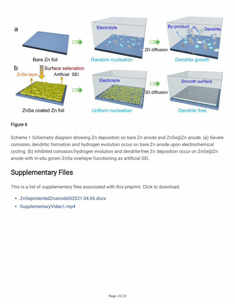
Figure 6
Scheme 1 Schematic diagram showing Zn deposition on bare Zn anode and ZnSe@Zn anode. (a) Severecorrosion, dendritic formation and hydrogen evolution occur on bare Zn anode upon electrochemicalcycling. (b) Inhibited corrosion/hydrogen evolution and dendrite-free Zn deposition occur on ZnSe@Znanode with in-situ grown ZnSe overlayer functioning as arti�cial SEI.
Supplementary Files
This is a list of supplementary �les associated with this preprint. Click to download.
ZnSeprotectedZnanodeSI2021.04.06.docx
SupplementaryVideo1.mp4