Date: 7/30/2006 9:10:59 AM
74
.! j:: e -Y*.:r- ' t ''! ' \ ''" I'J' 'f i':-"Y -' . K?',u I-) i+/ ,/''t"'l..'-l.;"{t t'"' ; { ' \ f il: " *,i-. ,,.1 r / * / i" #3 *:" )- i 1l7 /)' ,r ""'' i r 'r "' '' *, a s ii ' il t t il tl 'it x rltglfi mAl{tA] -Oi r I *,rEf
Transcript of Date: 7/30/2006 9:10:59 AM
.! j:: e
-Y*.:r- '
t ' '! ' \ ' '" I'J' 'f i ':-"Y -'. K ? ' , u I - ) i + / , / ' ' t " ' l . . ' - l . ; " { t
t ' " '; { ' \ fil: " *,i-. ,,.1 r /
* / i" #3 *:" )-
i 1l7 /)' ,r ""'' i r 'r "' ''* , a s
i i 'ilttiltl'itx
rltglfi mAl{tA]
- O i r I * , r E f
Or l idan a .s . Choce i565 37 Chocei, CSFRt e l . 0 4 6 8 / 9 5 2f a x . 0 4 6 8 / 9 5 ] - � 4 8 8
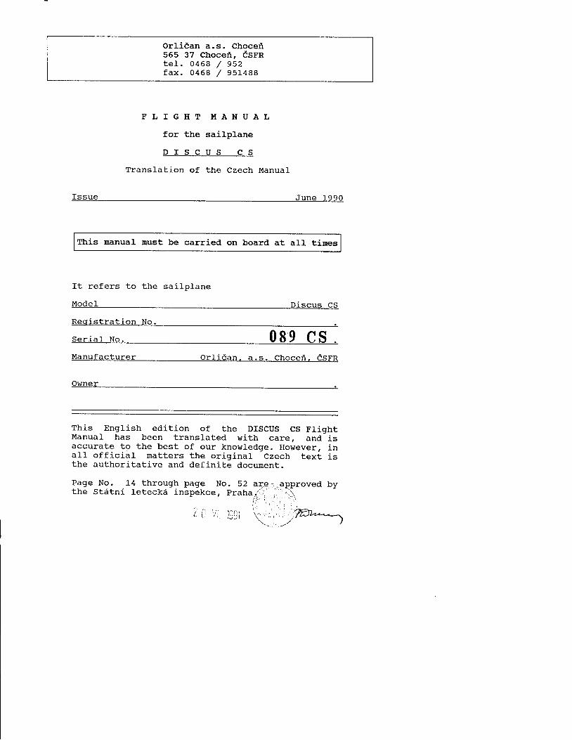
F L I G H T I , [ A N U A L
for the sai lplane
D I S C U S C S
Translat ion of the Czech Manual
Issue J u n e 1 9 9 0
This nanual must be carried on board at all times
It refers to the
ModeI
sa i lp lane
D i s c u s C S
Resist rat ion No.
s e r i a r N o . 0 8 9 C SManufac turer o r l idan , a .s . Choce i , CSFR
Owner _
This English edition of the DISCUS CS FlightManual has been translated with care, and isaccurate to the best of our knowledge. However, ina l l o f f ic ia l mat ters the or ig inal Czech text isthe authoritative and definite docurnent.
Page No. L4 through page No. 52 ar€- ,approved bythe Stdtni leteck6 inspekce, Prahaai ..11.
Discus CS FLIGHT I,IANUAL
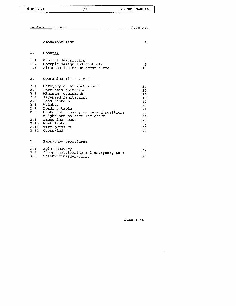
Tab le o f con ten ts paqe No.
Amendment l- ist
1 . Gene ra l
1 .1 cene ra l desc r i p t i onL.2 Cockpi t design and contro ls1.3 AJ-rspeed indicator error curve
2. operat ing l in i ta t ions
2. I Category of a i rworth j -ness2.2 Permi t ted operat ions2 .3 Minimurn equiprnent2.4 Ai rspeed l in i ta t ions2 .5 Load fac to rs2 . 6 W e i g h t s2 .7 Load ing tabLe2.a Center of grav i ty range and posi t ions
Weight and balance log chart2.9 Launching hooksZ . L U W E A K I . ] . N K S
2 . I I T i r e p r e s s u r e2 . L 2 C r o s s w i n d
3. Emergencv procedures
3 . 1 S p i n r e c o v e r y3 .2 Canopy je t t i son ing and emergency ex i t3 . 3 S a f e t y c o n s i d e r a t i o n s
June 1990
t 41 51 61 9
2 0
Z J
z o
2 7
5
z o
2 93 0
Discus CS - 1 / 2 - FLIGHT UANUAI
Tab le o f con ten ts
4 . Normal opera t ingr p rocedures
4.1 Da i ly inspec t j -on4 . 2 P r e - f l i g h t i n s p e c t i o n4 . 3 T a k e - o f f4 . 3 . 1 A e r o t o w i n g4 . 3 . 2 W i n c h l a u n c h i n g4 . 4 F r e e f l i g h t4 .5 Low speed f l igh t and s taL l4 . 6 H i g h s p e e d f l i q h t4 .7 F ty ing w j - th water ba l las t4 . 8 C l o u d f l y i n g4.9 F ly ing a t tempera tures be low4.10 Rest r i c ted aerobat ics4 . 1 1 A p p r o a c h a n d l a n d i n g
5. R iqg inq and de- r iqq inq
5 . 1 } ( r g g ] . n g5 . 2 D e - r i g g i n g5.3 Storage, hangar ing and towing5 . 4 C a r i n g f o r t h e s a i l p l a n e
Appendix
Perforrnance data
J I
3 53 53 5J I
3 94 04 5
4 5+ >
f reez ing po in t 495 15 2
June 1990
f J
5 65 75 B
6 .
Discus cs - 2 - FLIGHT I,IANUAL
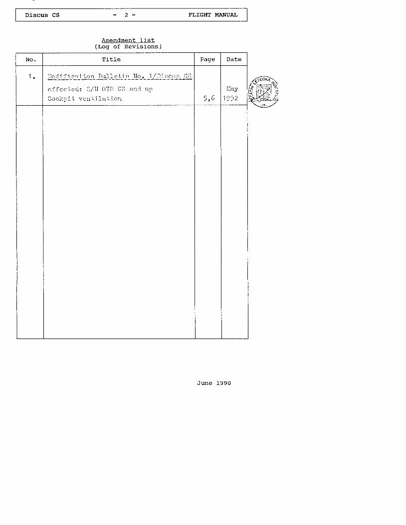
Arnendrnent list( r .og of Revis ions)
J u n e L 9 9 0
Ti t le
iTo d i i j. crr i.-Lcrr l}.r,i,1 e t in ldo ,
af . iec t ;ed: g/N A78 CS a.r :d l rp
Cocl t ; , i . t ; r r , : t r t i l i r ' . i -o : t
1 1
Discus CS - 3 - FI,IGHT MANUAIJ
1 . Genera l
Genera l Descr ip t ion
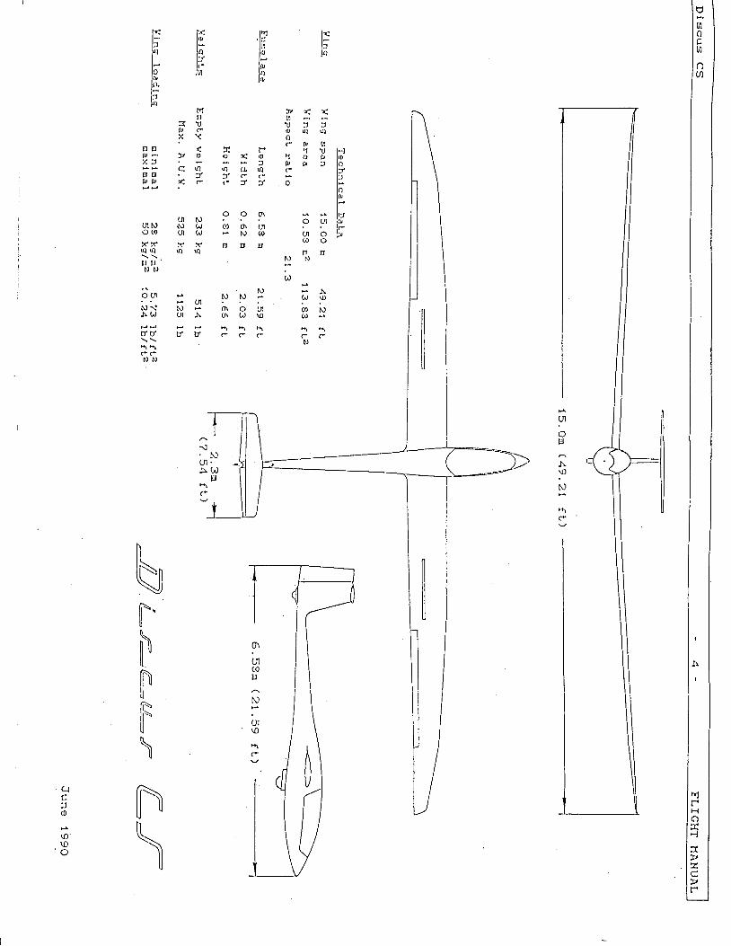
The D iscus CS is a s ing le -seat h iqh per fo rmancesailplane in CFRP/GFRP construction featuringa T- ta i1 (w i th f i xed hor izon ta l s tab i l i zer ande l e v a t o r ) .
Winqs
The two-piece wings each have a tr i- trapezoidalplan form, swept-back leading edge and lrtwo- storyrtairbrakes on the upper surface. Ai lerons havein te rna l - d r ive . Water baL las t tanks are in tegra lcompartments in the wing D nose, total capacityapprox . 184 l i te rs . Wing she l l s a re o f g lassfiber/foarn sandwich with spar f langes of carbonf iber rov ings and shear webs o f g lass f iber / foansandwich .
Fuse lage
The p i lo t has a semi - rec l in ing pos i t ion . Thecockpit is cornfortable. A one-piece canopy hingess ideways . The fuse lage she l1 i s a pure g lass f iberlay-up without sandwich and therefore is highlyenergy absorb ing . I t i s s t i f fened towards the ta i lwith GFRP/foam sandwich webs and the front fuseJ_agefeatures a double she11 on both sides and on thebottorn. The sprung undercarr iage is retractable andis f i t ted w i th a whee l b rake .
Hor izon ta l ta i lp lane
The hor izon ta l s tab i -L izer i s bu i l t in GFRp/ foarnsandwich and the elevator is a pure GFRP lay-up.
Ver t i ca l f in
Both f in and rudder are a GFRp/foam sand.wichcons t ruc t ion . The in tegra l water ba l las t tank in thef i n h a s a c a p a c i t y o f 6 . 5 k g ( L t r ) ( 1 . 7 2 U . S .G a L . / L . 4 3 I n p . c a l . ) .
J u n e 1 9 9 0
uo
t/)
a
n1rH
a'1-
v(-vr
N)
UI\o
l {l a
hlr'
llft;toj , l
Ir l<l: l,r,t J t *yt 14t t Yl- lFlo ltaIDl().l:r)4
r,tT '
? t rp cX \
} , ) ( ) Co F .
r U u l q
r p t r lf1 'rJ l-l
S r D r ! l op t ! f l oc t Y
t av l *
nt ' "t-
* l xo tr lo;
l cu o l r '( a o
r u : c oJ
t r l r ) . r n: l . c c
00 o\ crlN @
' N
!', l') :o \ o L I( n ( , J \ o
n a (N / . > r D> : f
c ( lE E . TP 0 ) C r
o O ar u l
N \ l NA( , UI A
U I Nu N , t J t ,tJ(O gt1 C{)
x r r x( | ( l a q
E T 'N N
9 v0 l NC 0 a
C ' ( .N
r\ h rrlt r rvcr
c cN N
nNF.NFfi\tr=\
n\
il
clf
r0
\o\oo
\. Nul .J\ OJ
uc*
Discus CS - 5 - FLIGHT MANUAL
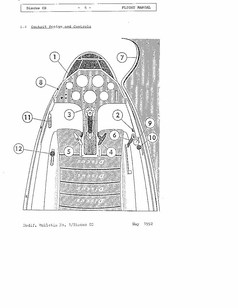
L . 2 C o c k p i t D e s i q n a n d C o n t r o l s
I r {odi f . 3u l le t in } Io . 1/Dir ;cus CS l c t c t ?
/ 1 \
\ z l
Discus CS - 6 - FLIGHT I'{ANUAL
(cockpi t Design and contro ls ,c td. )
All instrurnents and controls are within easy reachof the p i lo t .
Instrument panel
Two screws secure the instrument cover to the paneland to its tubular mounting frame. Panel rises underlight pressure after openlng the canopy.
Vent i - la t ion contro l
Small knurled knob on the starboard side of the cockpit.Regulat ion by freeing, rnoving and t j .ghtenlng up the knob.
Back$rard posit ion - Closed
Forward posit ion - Open
In add i t ion , the s l id ing w indow or the a i rscoop inthe window may be used for venti lat ion.
Wheel brake control
The wheel brake handle is mounted on the controls t i c k .
(4 ) Rudder peda l ad ius tment
Black T-shaped grip on the r i-ght side base. of theins t rument pane l conso le .
Forward adjustment:Re lease the lock ing dev ice by pu l l ing the T-gr lp .Push pedals with heels j-nto desired posit ion and1et thern engage the nearest notch.
Backward adjustment:Pul l pedals back with T-grip lnto desired posi-t ion . Forward pressure w i th hee ls (no t toes) w i l lengage pedals into the nearest notch with ana u d i b L e c L i c k .
The rudder pedals may be adjusted on the ground andi.n the ai-r.
Modif . BuTTetin No.7,/Discu.s C,S May 7992
Discus CS - 7 FLIGHT I,TANUAL
(cockp i t Des ign and Cont ro ls ,c td . )
(5 ) Launch inq hook re lease hand le
Yell ,ort T-shaped handle on the left at the base ofthe instrument panel console.
The w inch cab le ( tow rope) i s re leased by pu l l inqthe hand le .
(6 ) Land inq qear opera t inq lever
Retract : Unlock the black handle on the r ight atthe seat Pan suPport ' PuIl back andengage in rear recess .
Extend : Unlock black handle, push forward andengage in rear recess .
( 7 ) Canopy
The one-piece plexiglass canopy hinges sideways on f lushfi t t ings. Take care that the cable restraining the opencanopy is a t tached.
( B ) Canopv lockinq device
Lever control with red knob on the left on thecanopy frame.
Backward pos i t ion . . . . canopy locked
To open the canopy swing lever forward and raisecanopy.
(9 ) Canopy emerqencv je t t i son inq dev ice
stiding red knob on the r ight on the canopy frame.
Backward pos i t ion . . . . locked
To je t t i son the canopy ' f i r s t sw ing the lock inglever on the left on the canopy frame forward, raisecanopy,push the red jett ison knob on the r ight onthe inner skin forward and push canopy away.
J u n e 1 9 9 0
Discus cs - B FLIGHT I.{ANUAL
( C o c k p i t D e s i g n a n d C o n t r o l s , c t d . )
(10) Winq and f in tank water ba l las t durnp inq dev ice
Black ba l l -shaped knob on the r igh t in therniddLe of the GFRP inner skin.
Forward pos i t j -on : Va lves c losed
Backward posit ion = Valves open
To lock the valves open, push knob downwardsin to recess .
( 1 1 ) A i r b r a k e l e v e r
Blue lever on the left hand side of thecockp i - t .
Lever projects downwards.
Forward posit ion airbrakes closedand locked
Pulled back approx.4 0 m m ( L . 6 i n . ) = u n l o c k e d
Pulled ful ly back airbrakes ful1yextended
( 12 ) E leva tor t r i rn
Green knob on the left at the seat moldc r r n n n r { -
The spring operated elevator tr irn isgradually adjusted by moving the greenknob inwards , s l id ing i t in to the des i redpos i t ion and re leas ing i t to lock .
Forward position nose heavy
Backward posit ion tai l heavy
June l -990
DiscusCS - 9 - FL IGHTI , IANUAL
(Cockp i t Des ign and Cont ro ls ,c td . )
(13) Parachute r ip cord a t tachment (no t p ic tu red)
Red r ing , s i tua ted a t the f ron t o f thefuselage steel tube frarnework, left hands i d e .
J u n e 1 9 9 0
Discus CS - 1 0 - FLIGHT MANUAL
(cockpi t Design and contro ls ,c td. )
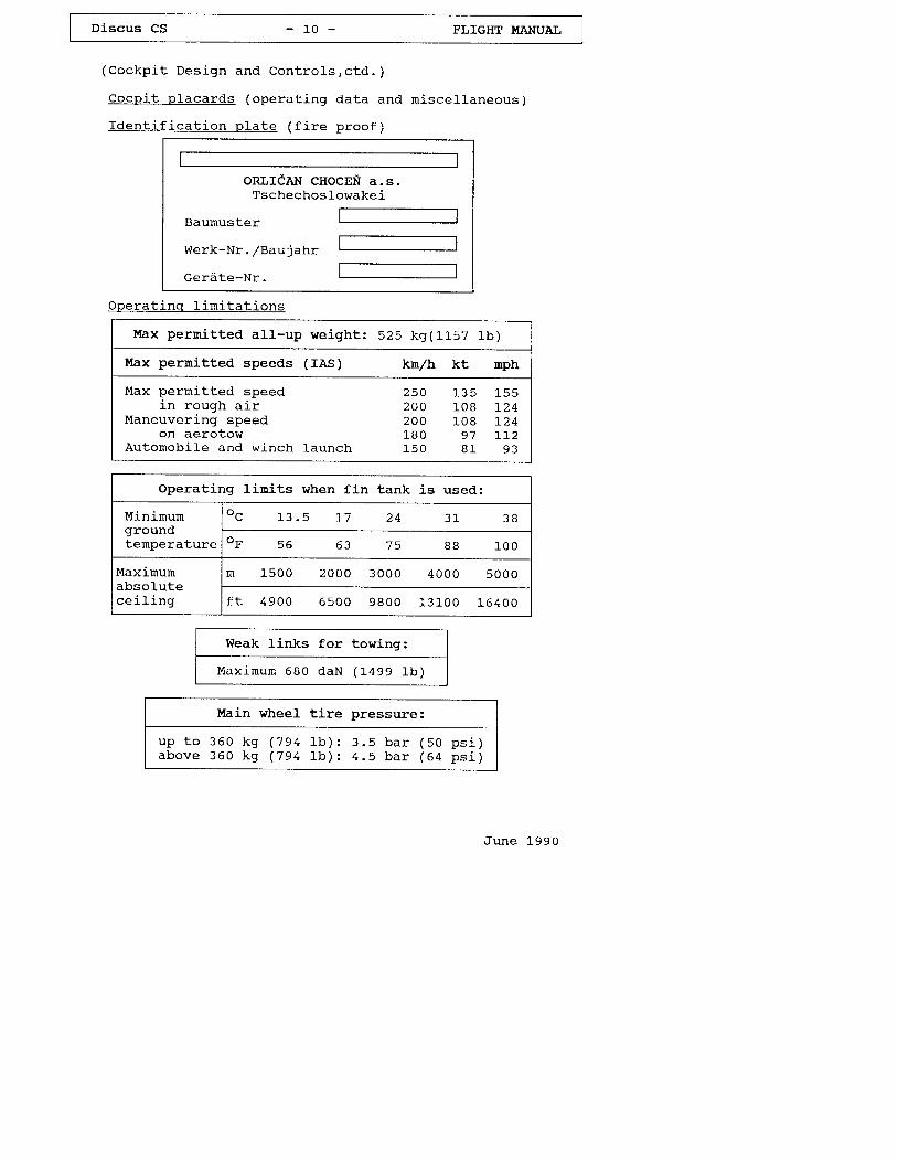
Cocpi t p lacards (operat ing data and miscel laneous)
fdent i f icat ion r : la te ( f i re proof)
ORLICAN CHOCEfr A.S.Tschechos lowake i
Baumuster
Werk-Nr . /Bau jahr
Gerdte-Nr
Weak links for towing:
Maximurn 680 daN (1499 lb )
June 1990
Operat inq l in i ta t ions
Max permi t ted a1l -up weight : 525 kg(1 i_57 1b)
Max pernitted speeds (IAS) kn/h kt nph
Max per rn i t ted speed 250 l_35 155in rough a i r 2OO 1OB 1-24
Maneuvering speed 2OO l_08 I24on aero tow 180 97 L I2
Autornobil-e and winch launch l_5O 81 93
operating l inits when fin tank is used:
Minirnurngroundtemperature
o c 1 3 . 5 1 7 2 4 3 1 J 6
f 5 6 7 5 B B L 0 0
Maximumabsolutecei l ing
n 1 5 0 0 2 0 0 0 3 0 0 0 4 0 0 0 5 0 0 0
f t 4 9 0 0 6 5 0 0 9 8 0 0 1 3 1 0 0 t 6 4 0 0
Main wheel t ire pressure:
u p t o 3 6 0 k g ( 7 9 4 1 � b ) : 3 . 5 b a r ( 5 0a b o v e 3 6 0 k g ( 7 9 4 1 � b ) : 4 . 5 b a r ( 6 4
psi )ps i )
Discus CS - 1 1 - FLIGHT UANUAL
(cockpi t Design and Contro ls ,c td. )
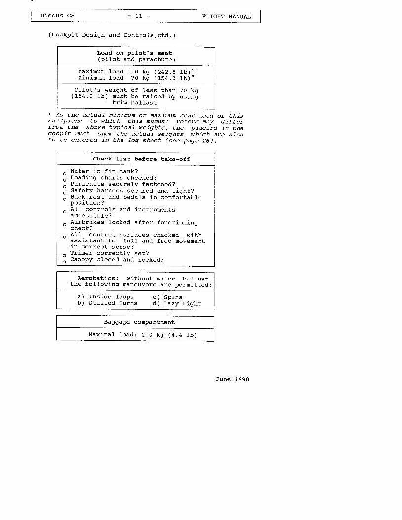
Load on p i lo t rs seat(p i Io t and parachute)
M a x i m u r n l o a d 1 l - o k q ( 2 4 2 . 5 1 b ) 1M i n i r n u n l o a d 7 0 k g ( 1 5 4 . 3 1 b ) *
P i lo t rs we igh t o f less than 70 kg( 1 5 4 . 3 1 b ) m u s t b e r a j _ s e d b y u s i n g
t r im ba l las t
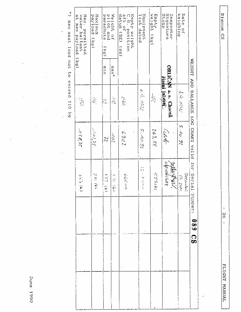
* As the actuaL mininum or maxinum seat Load of thissai lplane to which this manual refers may dif ferfron the above typical weights, the pjacard jn thecocpit nust show the actuai weights which are aLsoto be entered in the 1og sheet (see page 26).
Check l ist before take-off
^ Water in f in tank?
I r,oading charts checked?
o Parachute securely fastened?
o Safety harness secured and t ight?
o Back . res t and peda ls in confor tab tepos].E].on a
^ A11 controLs and instrurnents" a c c e s s i b L e ?
o Airbrakes locked after functioning" check?
^ A11 cont ro l sur faces checked w i th- ass is tan t fo r fu11 and f ree movemencin cor rec t sense?
o Trimer correctly set?
o Canopy closed and l_ocked?
Aerobatics: without water ballastthe fol]owing rnaneuvers are perrni_tted:
Ins ide loops c ) Sp insSta lLed Turns d) Lazy E iqh t
a )b )
Baggage compartment
M a x j - m a 1 l o a d : 2 . 0 k g ( 4 . 4 I b )
June 1990
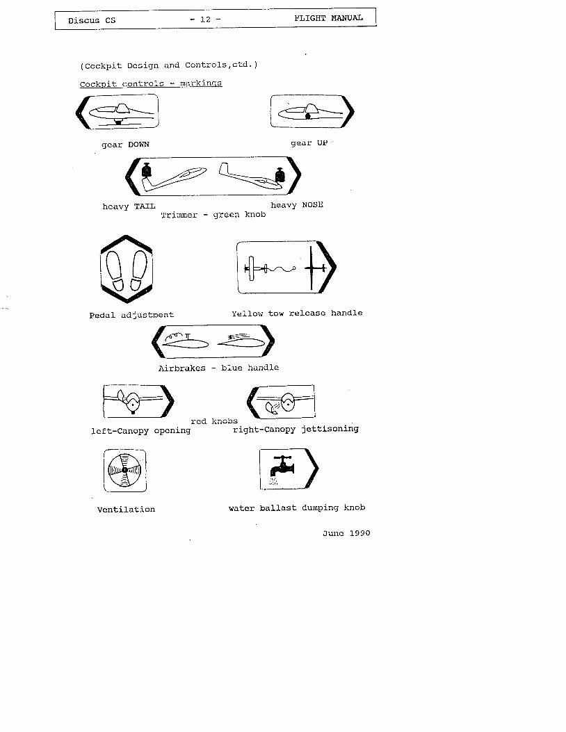
( c o c k p i t D c s i g n a n d C o n t r o l s , c t d . )
Cockp i t con t ro ls - mark inqs
gear DOWN
heavy TAIL
gear UP
NOSEheavyTrimrner - green knob
#-^-fiPedal adjustment Ye l low tow re lease hand le
Airbrakes - blue handLe
vtre(t
left-CanoPY oPening
Venti lat ion
right-CanopY jettisoning
water ballast dumPing knob
June 1"990
knobs
Discus CS - L 2 a - FI,IGHT MANUAII
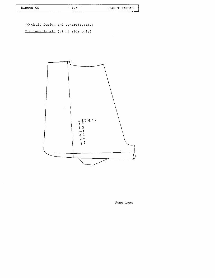
(Cockp i t Des ign
F i n t a n k l a b e l :
a n d C o n L r o l s , c t d . )
( r i g h t s i d e o n l y )
J u n e L 9 9 0
Discus CS - L 3 - FLIGHT UANUAL
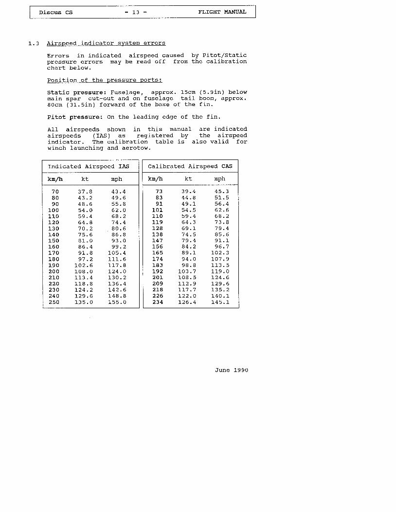
1.3 Ai rspeed indicator system errors
Errors in indicated airspeed caused by eitotrzStaticpressure errors may be read off from the calibratj-onchart below.
Pos i t ion o f the pressure por ts :
S ta t i c p ressure : Fuse lagef approx . l -scn (5 .9 in ) be lowrna in spar cu t -ou t and on fuse lage ta i l boornr approx .B 0 c n ( 3 1 . . 5 i n ) f o r w a r d o f t h e b a s e o f t h e f i n .
Pitot pressure: on the leading edge of the f in.
A11 airspeeds shown in this rnanual are indicateda i rspeeds ( IAs) as reg is te red by the a i rspeedind ica tor . The ca l ib ra t ion tab le i -s a lso va l id fo rwinch launching and aerotow.
Indicated Airspeed fAS
kn/h
7 08 09 0
LooL L oL201 3 0140L501 6 0170L80L902 0 02LO220230240250
1 , !
-J T . 6
4 8 . 65 4 . 05 9 . 46 4 . 87 0 . 2a q a
8 1 . O8 6 . 40 1 0
9 7 . 2L O 2 . 61 0 8 . 01 4 1 A
r 1 8 . 8L 2 4 . 21 , 2 9 . 61 3 5 . 0
nph
4 9 . 65 5 . B6 2 . O6 a . 2
d u . o
6 0 . d
9 3 . 09 9 . 2
1 0 5 . 41 1 1 . 6r a / - o
1 3 6 . 4r 4 2 . 61 4 8 . B1 5 5 . 0
Calibrated Airspeed CAS
kn/h
7 3B 39 1
t 01_1 1 01l-91241 3 8L471 5 6L 6 5L 7 4l_83L9220L2092 L B2 2 6234
kt
3 9 . 44 4 . 84 9 . 15 4 . 55 9 . 40 4 . J
6 9 . 17 4 . 5
t 3 4 . Z
a o 1
9 4 . O9 8 . B
1 0 3 . 71 0 8 . 5I L 2 . 9I T 7 . 7
L 2 6 . 4
nph
4 5 . 35 1 . 55 6 . 46 2 . 6t J . J . z
7 3 . 47 9 . 48 5 . 6o 1 1
a A ' 7
r o 2 . 31 0 7 . 91 1 4 F
1 1 0 n
) . 2 4 . 6r 2 9 . 6I 3 5 . 21 4 0 . 11 4 5 . 1
June l -990
Discus CS - ] - 4 - FTJIGHT I,IANUAI'
2 .
2 . L
opera t inq L in i ta t ions
Cateqorv o f A i rwor th iness
Category r rUr r (Ut i l i t y ) accord ing to JAR 22.
Accord ing to the requ i rements o f JAR 22, fu l1control surface deflect ions may be applied up to themaneuverj-ng speed VO.
At h igher speeds, when us ing fu11 cont ro l sur facedeflect ions, i t would be possj-bJ-e to exceed thes t ress l i rn i ts o f the sa i lp lane.
For th is reason, fu l t de f lec t ion o f con t ro ls mustnot be used at speeds above 200 krn/h ( 108 kt , L24n p h ) .
A t max imum permi t ted speed Vwn : 250 kn /h (L35 k t ,155 nph) , on ly a max imum of "5ne th i rd o f the fu l Icon t ro l de f lec t ion is permi t ted .
For the e leva tor , the de f lec t ions a t V \TF are evenconsiderably smal- ler and depend on t l iS perrnit tedmaneuvering foad factors.
In normal weather cond i t ions , th is sa i lp lane can bef lown a t speeds up to VNF : 25O kmrzh (135 k t , 155rnph) w i thout p rob lems.
In severe turbulence, i .e . wavethunderstorms, visible whirlwinds and whenmountain r idges, Vpa = 2OO kn/h (108 kt ,must not be exceedeil. '
roEors Icrossing124 mph)
June l -990
Di-scus CS - 1 5 - FLIGHT MANUAI,
2.2 Permi t ted operat ions
1. vFR Flying in daYtine
(Mini rnurn equiprnent according to sect ion 2.3a) .
2. c loud Fly ing
(Minimum equipment according to sect ion 2.3b) .
3. Restricted Aerobatics:
The fol lowing aerobatics maneuvers are permitted:
a) Ins ide Loop
b ) S p i n s
c) S ta l led Turn
d) Lazy E igh t
In add i t ion to the equ iprnent l i s ted in sec t ion 2 .3it is recommended to equip the sai lplane withacce le roneter (3 hands , rese t tab le ) , i f i t i s to beused fo r aerobat ics .
June 1 ,990
Discus cs - 1 6 - FI,IGHT UANUAL,
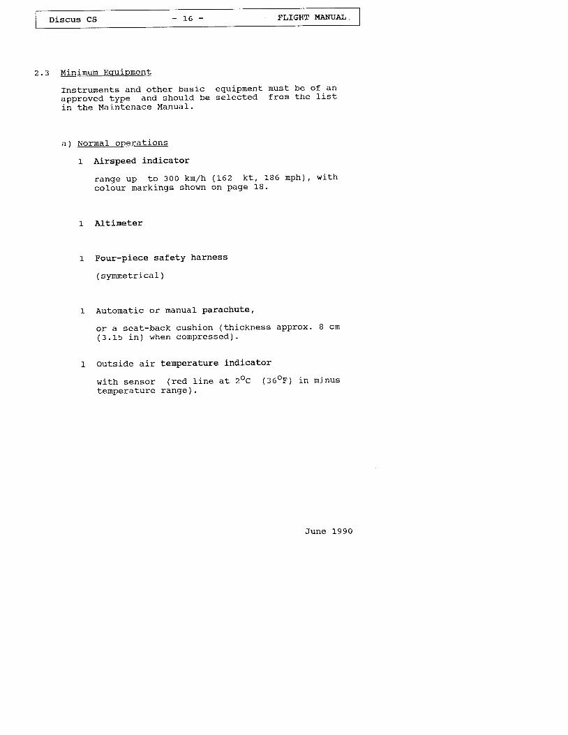
2 .3 Minirnurn Equipnent
Instruments and other basic equipment must be of an
approved type and should be selected fron the l ist
in the Main tenace Manua l .
a ) Norma1 oPera t ions
1 AirsPeed indicator
range up to 300 kn /h (162 k t , 186 mph) ' w i th
colour rnarkings shown on Page 18.
1- Altineter
1 Four-piece safetY harness
( symmetrical )
1 Automatic or manual Parachute'
or a seat-back cushion ( th ickness approx. 8 cm( 3 . 1 5 i n ) w h e n c o m P r e s s e d ) .
1 outside air temperature indicator
wi th sensor ( red l ine at 2oc (36oF) in rn inustemperature range).
June 1990
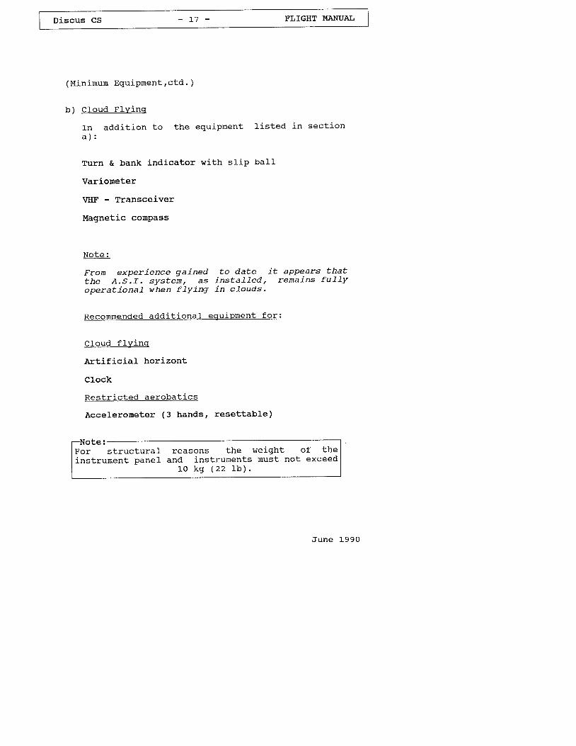
Discus CS - L 7 - FLIGHT MANUAL
(Min i rnum Equipment ,c td. )
b) C loud F lv j -nq
In add i t ion toa ) :
the equiprnent l isted in sectj-on
Turn & bank indicator
Variorneter
VIIF - Transceiver
Magnetic compass
No te :
wi th s l ip ba l l
From experience gained to date it appears thatthe A.S. f . sys tem, as ins ta l led , remajns fu1 lyoperationaL when f lying: in cLouds.
Reconmended addit ionaL equiprnent for:
c loud f l y inq
Art i f ic ial horizont
Clock
Rest r i c ted aerobat ics
Acceleroneter (3 hands, resettable)
Note:For structuralinstrument panel
reasons theand instruments
L0 kg (22 l - b ) .
weight of themust not exceed
June 1990
-: ---:-_
-l
I niscus cs - 18 - t"t"n. **Arl__l
(Min i , rnum Equipnent ,c td. )
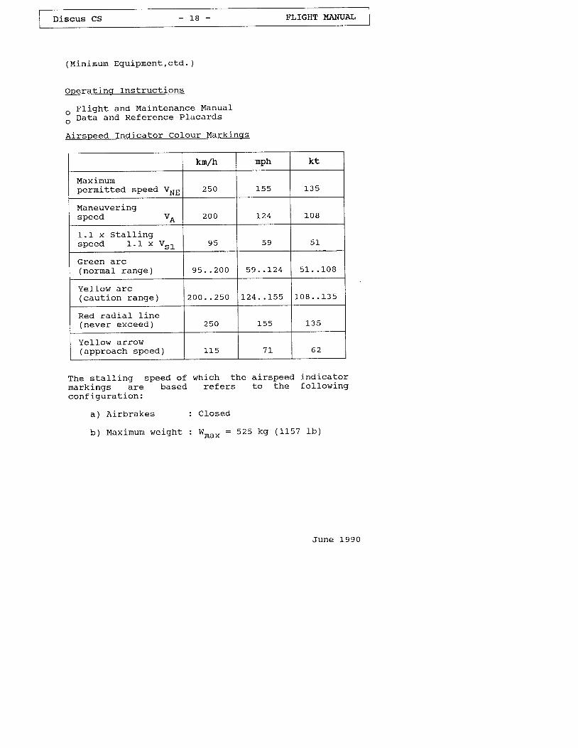
operatinq fnstructions
^ Fl ight and Maintenance Manual
I nata and Reference Placards
Airspeed Indicator Colour Markj-nqs
kn/h nPh kt
Maximumpermitted speed V"" 250 1 5 5
Maneuveringspeed VA 2 0 0 L24 1 0 8
1 . 1 x S t a l l i n gs p e e d 1 . 1 x V s l 5 9
Green arc(nornaL range) 9 5 . . 2 0 0 5 9 . . L 2 4 5 1 . . 1 0 8
Ye l " low arc(caut ion range) 2 0 0 . . 2 5 0 L 2 4 . . r 5 5 1 0 8 . . 1 3 5
Red rad ia l l i ne(never exceed) 250 -L J . f
Yel1ow ar row(approach speed) 1 1 F 7 I 0 z
The stal l ing speed of which the airspeed indicatormarkings are based refers to the fol lowingconf igura t ion :
a) A i rb rakes : C losed
b) Max inum we igh t t W*u. * = 525 kg (1157 lb )
June 1990
Discus CS - 1 9 - FLIGHT I'TANUAL
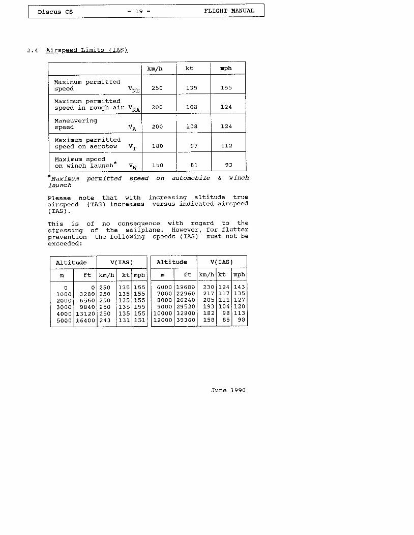
2 . 4 A i r s p e e d L i m i t s ( f A S )
krnrzh kt mph
Maxirnum permitteospeed VNn 250
Maximurn perrnittedspeed in rough air V* 200 I U O L Z +
Maneuveri-ngspeed VA 2 0 0 1 0 8 L24
Maximurn perrnittedspeed on aerotow VT 1 8 0 9 7 1r2
Maximum speed +on winch launch- vw 1 E n B 1 9 3
*Mu*i^u^ pernit ted speed on autonobiLe & winchlaunch
Please note that with increasing alt i tude truea i rspeed (TAS) inc reases versus ind ica ted a i rspeed( r A s ) .
This is of no consequence with regard to thestressing of the sai lp lane. However, for f lu t terprevent ion the fo l lowing speeds ( IAS) nust not beexceeded:
Altitude v( rAs )
m € + km/h 1 - ! nph
01 0 0 02 0 0 03 0 0 04 0 0 05 0 0 0
o3 2 8 06 5 6 09 8 4 0
L3),20L 6 4 0 0
250250250250250243
1 3 51 3 5L 3 5t 3 51.3 5l_3 I
1 5 51 5 51 5 51 5 51 5 s1 5 L
Altitude v( rAs )
f t kn/h nph
6 0 0 07 0 0 08 0 0 09 0 0 0
1 0 0 0 01.20 0 0
t -96802296026240295203 2 8 0 03 9 3 6 0
230
205L v J
L 6 Z
t_58
124L]-71_11
9 BB 5
t-4 3
L 2 7
1 1 39 B
June 1990
Discus cS - 2 0 - FLIGHT I'IANUAI
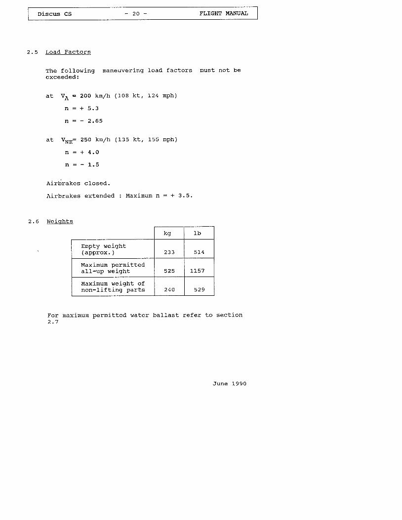
2 .5 Load Fac to rs
The following rnaneuvering load factors must not beexceeded:
at Va = zo0 ktn/h (108 kt , 1-24 rnPh)
n : + 5 . 3
n : - 2 . 6 5
a t V "u : 250 kn /h (135 k t , 155 mPh)
n = + 4 . 0
n = - l - . 5
Airbrakes c losed.
Airbrakes extended : Maximum n = + 3.5.
2 . 6 W e i q h t s
kg Ib
Ernpty weight(approx. ) 233 5 1 4
Maximum permittedall-up wej.ght 525 L L 5 7
Maximum weight ofnon- l i f t ing par ts 2 4 0 529
For maximunr perrnitted water ballast refer to section
June L99O
Discus CS - 2 r - FLIGHT }TANUAL
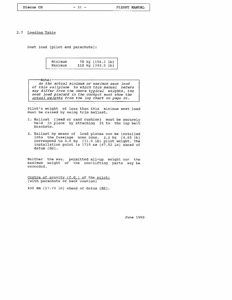
2 . 7 L o a d i n q T a b l e
S e a t l o a d ( p i 1 o t a n d p a r a c h u t e ) :
Minimurn 70 kg ( 154 . 3 1b )Maxirnurn L l -O kg (242.5 l . 'b)
As the actuaL minimum or maximun seat l-oadof this sai lplane to which this nanuaL refersnay differ from the above typical weights, theseat Load pLacard in the cockpit nust show theactua] weiqhts fron the 1og chart on page 26.
P i lo t rs we igh t o f less than th is mj -n imum seat loadrnus t be ra ised by us ing t r i rn ba l las t .
1 . Ba l las t ( Iead or sand cush ion) must be secure lyhe ld in p lace by a t tach ing i t to the lap be l tb rackets .
2 . Ba l las t by means o f lead p la tes can be ins ta l ledi n t o t h e f u s e l a g e n o s e c o n e . 2 . 2 k g ( 4 . 8 5 l b )c o r r e s p o n d t o 5 . 0 k g ( 1 1 . 0 1 b ) p i l o t w e i g h t . T h ei n s t a l l a t i o n p o i - n t i s 1 7 1 5 n m ( 6 7 . 5 2 i n ) a h e a d o fd a t u m ( B E ) .
Neither the max. perrnitted all-up weight nor thernaxj-mum weight of the non-l"ift ing parts rnay beexceeded.
C e n t r e o f q r a v i t v ( C . G . ) o f t h e p i l o t :(with parachute or back
4 5 O m m ( 1 , 7 . 7 2 i n ) a h e a d
^ , , ^ L ; ^ - \u u D r I I 9 l l ,
o f d a t u m ( B E ) .
J u n e 1 9 9 0
Discus CS - 2 2 - FLIGHT MANUAI,
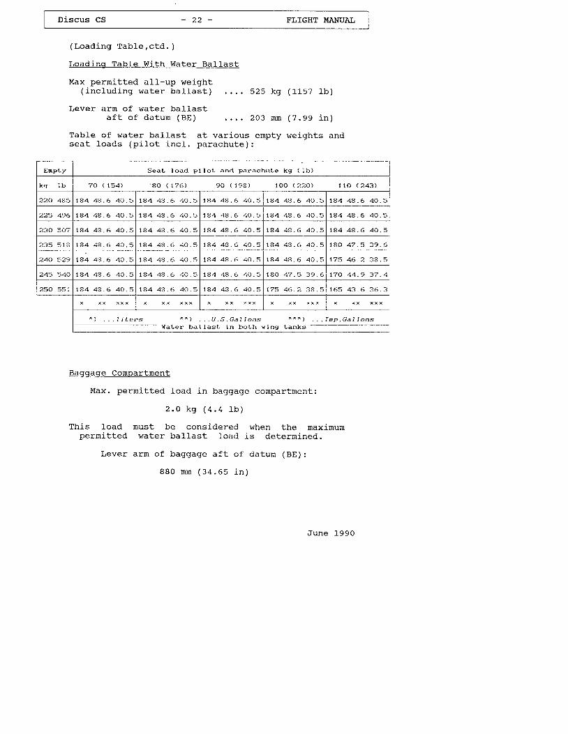
( L o a d i n g T a b l e , c t d . )
Load inq Tab le Wi th Water Ba l las t
Max permitted al l-up weight( i n c l u d i n g w a t e r b a l l a s t ) 5 2 5 k g ( L l - s 7 l b )
Lever a rm o f water ba l las ta f t o f d a t u m ( B E ) 2 0 3 n n ( 7 . 9 9 i n )
TabLe of water bal last at various ernpty weights ands e a t l o a d s ( p i I o t i n c l . p a r a c h u t e ) :
Baggaqe Compartment
Max. permj.tted load in baggage compartment:
2 . 0 k 9 ( 4 . 4 l b )
This load must be considered when the maximumpermit ted water bal last load is deterrn ined.
Lever arm of baggage af t o f datum (BE):
B B 0 n n ( 3 4 . 6 5 j - n )
J u n e 1 9 9 0
EnpLy S e a t l o a d I ) i l o t a n d p a r a c h u L e ks l b )
k g l b 7 0 < 1 5 4 ) ' 8 0 ( 1 7 6 ) 9 0 ( 1 9 8 ) 1 0 0 ( 2 2 0 ) 1 1 0 ( 2 4 3 )
220 485 7 4 4 4 4 . 6 4 0 . 5 t a 4 4 s . 5 4 0 . 5 1 A 4 4 8 . 6 4 0 . 5 t a 4 4 a . 6 4 0 . 5 1 4 4 4 4 . 6 4 0 . 5
225 496 1 4 4 4 8 . 6 4 0 . 5 7 4 4 4 3 . 6 4 0 . 5 7 4 4 4 4 . 6 4 0 . 5 1 4 4 4 S . 6 4 0 . 5 7 4 4 4 4 . 6 4 0 . 5
230 507 7 4 4 4 8 . 6 4 0 . 5 1 A 4 4 e . 6 4 0 . 5 t a 4 4 8 . 6 4 0 . 5 1 4 4 A e . 6 4 0 . 5 7 a 4 4 8 . 6 4 0 . 5
2 3 5 5 1 S r 8 4 4 e . 6 4 0 . 5 7 A 4 4 3 . 6 4 0 . 5 7 4 4 4 4 . 6 4 0 . 5 1 4 4 4 8 . 6 4 0 . 5 7 A O 4 ? . 5 3 9 . 6
240 529 1 8 4 4 8 . 6 4 0 . 5 1 8 4 4 8 . 6 4 0 . 5 7 8 4 4 4 . 5 4 0 . 5 r a 4 4 8 . 6 4 0 . 5 1 7 5 4 6 . 2 3 e . 5
245 1 4 4 4 4 . 6 4 0 . 5 1 S 4 4 8 . 6 4 0 . 5 7 4 4 4 4 . 6 4 ( ) . 5 1 a o 4 7 . 5 3 9 . 5 7 7 0 4 4 . 9 3 7 . 4
250 551 t a 4 4 3 . 6 4 0 . 5 t a 4 4 a . 6 4 0 . 5 t 8 4 4 4 . 6 4 0 . 5 1 7 5 4 6 . 2 3 8 . 5 7 6 5 4 3 . 6 3 6 . 3
x x x x x x
. . . I i L e r s * " ) . . . U . , S . G a | | o n s . . I n e . G a l l o n sH a L e r b a l l a s L i n b o L h v i n g L a n k s
-
Discus cs - 2 2 a - FLIGIIT I,IANUAL
( L o a d i n g T a b l e , c t d . )
Load ing Tab le When Us inq The F in Tank
In order to shi f t the center of grav i ty c lose to i tsaf t l in i t ( favourable in terrns of per formance),water bal last may be carr ied in a f in tank ( rno ' .n) tocompensate for the nose heavy moment of
'f iater
ba l l as t i n t he w ing (np1 ) .
The deterrnination of the balLast quantity is donewi th the a id of the d iagran on page 22 d.
June L990
Discus CS - 2 2 b - FLIGHT I,IANUAL
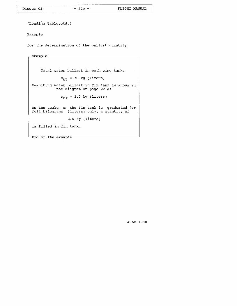
( L o a d i n g T a b l e , c t d . )
Example
for the deterrnination of the ba l las t quant i t y :
-Examp
Total water ballast in both winq tanks
nwT = 70 kg ( l i t e r s )
Resulting water ballast in fin tank as shown inthe d iagram on page 22 d:
n F T : 2 . 0 k g ( l i t e r s )
As the scale on the fin tank is graduated forfu l l k i lograms ( l l ters) on1y, a quant i ty of
2 . 0 k g ( l i t e r s )
i s
-End
f i I1ed in f i -n tank .
of the exampl
June 1990
Discus cs - 2 2 c ' FLIGHT I.fANUAL
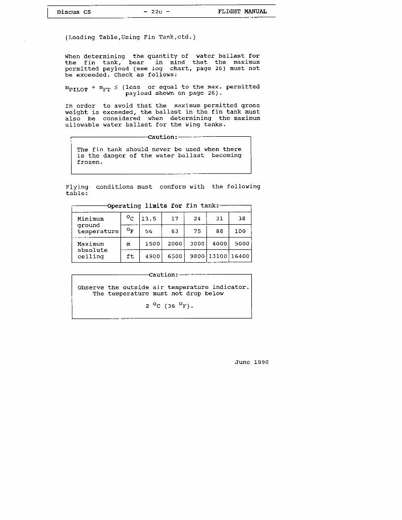
(Loading Table,Using Fin Tank,ctd. )
When determining the quantity of waterthe fin tank, bear in rnind thatpermi t ted payload (see 1og char t , pagebe exceeded. Check as fo l lows:
ba l las t fo rthe maximum26 ) must not
mpILoT + mFT < (less or equal to the max. permittedpayload shown on Page 26) .
In order to avoid that the maximum pernitted grossweight is exceeded, the ballast in the fin tank rnustalso be considered when deterrnining the rnaximumal lowab1e water bal last for the wing tanks.
Flying c.onditions must conform withtab le :
the following
Iinits f f i
ution:
observe the outsideThe temperature
air temperature indicator.must not drop below
o c 1 : e o r ' ; .
June 1990
The f in tank should neveris the danger of the waterf r o z e n .
be used when therebal. last becoming
peraErng lrmrEs lor r].n EanK:
Mininurngroundtemperature
oc L 7 J O
oF 5 6 6 3 7 5 o o l _00
Maximumabsolutecei l ing
m 1 5 0 0 2 0 0 0 3 0 0 0 4 0 0 0 5 0 0 0
f t 4 9 0 0 6 5 0 0 9 8 0 0 1 3 1 0 0 1 _ 6 4 0 0
Discus CS - 2 2 d - FLIGHT I,IANUAL
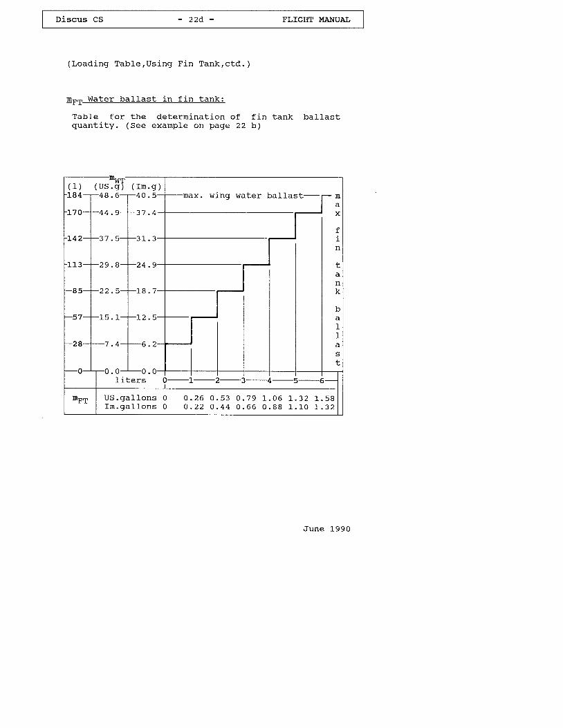
( L o a d i n g T a b l e , U s i n g F i n T a n k , c t d . )
rn - - Water ba l las t in f in tank :
Table for the determination ofquant i t y . (See example on page 22
f in tank b a l l a s t
June 1990
( r m . s )
L42--+-37 .
l i ters
x. wing water bal last -
U S . g a l l o n s 0 O . 2 6 O . 5 3 0 . 7 9 L . 0 6 1 . 3 2 1 . 5 8f m . g a l l o n s 0 O . 2 2 O . 4 4 O . 6 6 O . 8 8 1 . 1 0 1 " . 3 2
Discus CS - 2 3 - FLIGHT I,IANUAL
2 . 8 C . G . P o s i t i o n s
a ) I n - f l i q h t C . G . p o s i t i o n
Sailplane att i tude : Tai l jacked up such thata wedge-shaped b lock L00 : , 4 .4 , p laced on thefuse lage ta i l boorn , i s hor izon ta l a long i t s upperedge.
Datun (BE) Wing lead ing edge a t roo t r ib
Max. forwardC . G . p o s i t i o n . . . 2 6 0 m m
a f t
Max. rearwardC . G . p o s i t j - o n . . . 4 0 0 n n
af t
( 1 " o . 2 4 i n )o f d a t u n ( B E )
( 1 . 5 . 7 5 i n )o f da tun (BE)
b )
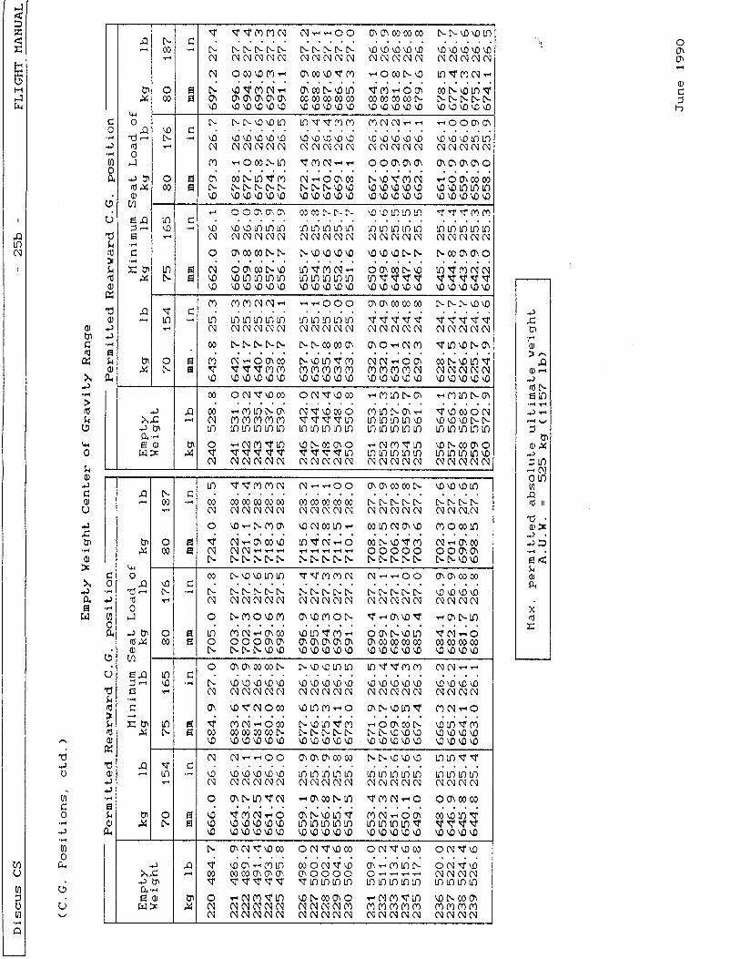
Make sure that the maximurn pernitted rearwardC.G. posi t ion is not exceeded - th is is ensuredwhen the minimum seat load (pi-Iot and parachute)is observed.A lower seat load must be compensated by ba11ast .( See sect ion 2,7 r t t loading tablet t ) .
E r n n t v w e i o h t C - G - n o s i t i o n
Af te r repa i r , repa in t ing , i -ns ta l la t ion o faddit ional equi-pment, rnodif icat ions etc. thecenter of gravity must be re-determined byweigh ing the sa i lp lane; in any case the D iscus CSshould be re-weighted every four years. Make surethat the ernpty C.c. is within the perrnit tedrange. f f necessary , cornpensat ing ba l las t we igh trnus t be ins ta l led .
When the empty weight C.c. l ini ts and the loadingtab le a re observed, the C.G. pos i t ion in f l i .gh tw i l l be w i th in the pern i t ted range.
J u n e 1 9 9 0
Discus cS - 2 4 - FLIGHT }IANUAL
( C . G . P o s l t i o n s , c t d . )
The deterrnination of the C.G. ranges as shown in thed iagrams on page 25 A and 25 S is done w i th thefo l low ing seat loads :
ForwardC.G. Pos i t ions : Wi th a rnax imurn seat load o f 1LO kg
( 2 4 2 . 5 1 b ) a n d w i t h m a x . p e r r n i t t e dwater ba l las t
RearwardC.G. Pos i t ions : Wi th var i -ous rn in imurn seat loads and
w i t h 2 . 0 k g ( 4 . 4 1 b ) l o a d i n t h ebaggage compartment
For easier deterrnination of the rtemptyrt weightC .G .pos i t i on ' t he t ab le on page 24 A shows , a tvarious ernpty weights, the maxirnurn permissibLe loadson the ta i l sk id (or wheel - i f insta l led) wi thvarious seat l-oads (with reference to the rearmostc / c pos i t i on ) .
Just determj-ne the actual load on the tai l skid (orwheel) with the sai lplane being in weighing att i tude(na in whee l on the ground, ta i l jacked up as descr ibedon page 23 ) .
I f the deterrnined Load on the tai l skid (or wheel - i fins ta l led) i s be low the va lue shown on page 24 A, theC.G. pos i t ion is w i th in the per rn i t ted range.
J u n e L 9 9 0
Discus CS - 2 4 a - FLIGHT I'IANUAL
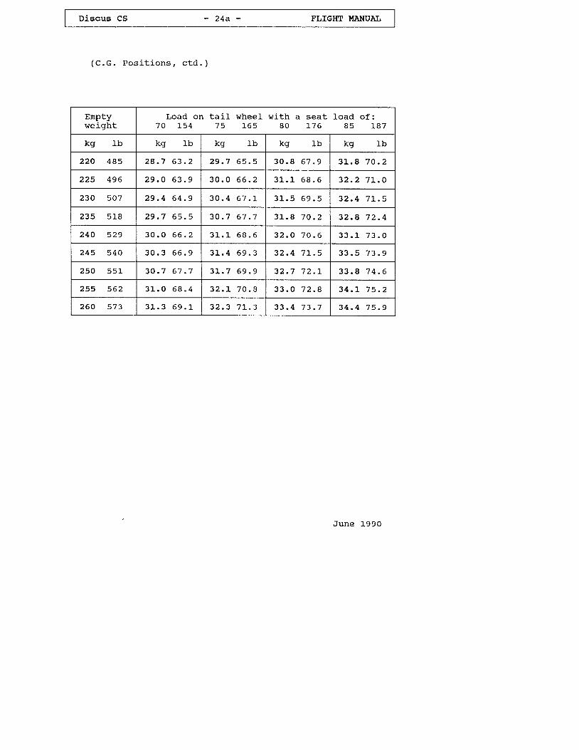
( C . G . P o s i t i o n s , c t d . )
June 1990
Enptyweight
Load on ta i l whee l w i th a seat Load o f :7 0 ] - 5 4 7 5 1 6 5 8 0 ] - 7 6 8 5 1 8 7
kg kq Ib kg t h kg 1 L kg 1b
220 485 2 8 . 7 6 3 . 2 2 9 . 7 6 5 . 5 3 0 . B 6 7 . 9 3 L . 8 7 0 . 2
2 2 5 4 9 6 2 9 . 0 6 3 . 9 3 0 . 0 6 6 . 2 3 L . L 6 8 . 6 3 2 . 2 7 L . O
230 507 2 9 . 4 6 4 . 9 3 0 . 4 6 7 . I 3 l _ . 5 6 9 . 5 3 2 . 4 7 L . 5
235 5L8 2 9 . 7 6 5 . 5 3 0 . 7 6 7 . 7 3 L . A 7 0 . 2 3 2 . 8 7 2 . 4
240 529 3 0 . 0 6 6 . 2 3 L . 1 6 8 . 6 3 2 . O 7 0 . 6 3 3 . 1 7 3 . 0
245 540 3 0 . 3 6 6 . 9 3 l _ . 4 6 9 . 3 3 2 . 4 7 L . 5 3 3 . 5 7 3 . 9
250 551 3 0 . 7 6 7 . 7 3 L . 7 6 9 . 9 3 2 . 7 7 2 . 1 , 3 3 . 8 7 4 . 6
255 562 3 1 " . 0 6 8 . 4 3 2 . 1 7 0 . B 3 3 . O 7 2 . 8 3 4 . L 7 5 . 2
260 573 3 L . 3 6 9 . 1 3 2 . 3 7 L . 3 3 3 . 4 7 3 . 7 3 4 . 4 7 5 . 9
Discus CS - 2 5 a - FLIGHT I'{ANUAL
( c . G . P o s i t i o n s , c t d . )
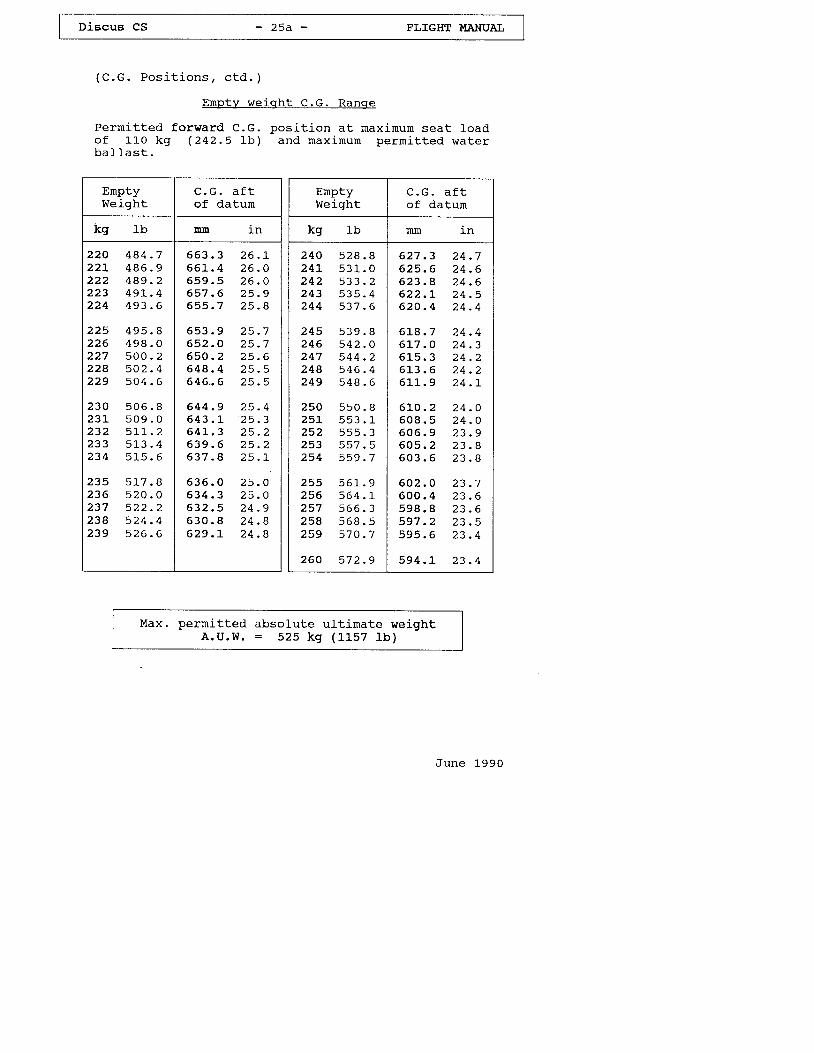
Empty we ic rh t C.G. Ranqe
Permitted forward C.G. posj-t ion at maxirnum seat loadof 11o kg (242.5 1 ,b ) and max imum per rn i t ted waterb a 1 1 a s t .
EnptyWeight
^ G +U - U - d I L
of datum
Ibkg mm
2 2 0 4 A 4 . 72 2 L 4 8 6 . 92 2 2 4 A 9 . 22 2 3 4 9 L . 42 2 4 4 9 3 . 6
2 2 5 4 9 5 . 82 2 6 4 9 8 . 02 2 7 5 0 0 . 22 2 4 5 0 2 . 42 2 9 5 0 4 . 6
2 3 0 5 0 62 3 L 5 0 92 3 2 5 1 12 3 3 5 1 32 3 4 5 1 5
2 3 5 5 1 7 . 82 3 6 5 2 0 . 02 3 7 5 2 2 . 22 3 4 5 2 4 . 42 3 9 5 2 6 . 6
6
0
o
6 5 3 . 3 2 6 . L6 6 I . 4 2 6 . O6 5 9 . 5 2 6 . O6 5 7 . 6 2 5 . 96 5 5 . 7 2 5 . 8
6 5 3 . 9 2 5 . 76 5 2 . O 2 5 . 76 5 0 . 2 2 5 . 66 4 4 . 4 2 5 . 56 4 6 . . 6 2 5 . 5
6 4 4 . 9 2 5 . 46 4 3 . 1 2 5 . 36 4 L . 3 2 5 . 26 3 9 . 6 2 5 . 26 3 7 . 8 2 5 . L
6 3 6 . O 2 5 . O6 3 4 . 3 2 5 . O6 3 2 . 5 2 4 . 96 3 0 . B 2 4 . 86 2 9 . L 2 4 . 8
EnptyWeight
C . G . a f tof datum
Ibkg I Nnm
2 4 0 s 2 8 . B2 4 L 5 3 1 . 02 4 2 5 3 3 . 22 4 3 5 3 5 . 42 4 4 5 3 7 . 6
2 4 5 5 3 9 . B2 4 6 5 4 2 . O2 4 7 5 4 4 . 22 4 8 5 4 6 . 42 4 9 5 4 8 . 6
2 5 0 5 s 0 . 82 5 L 5 5 3 . 12 5 2 s s 5 . 32 5 3 5 s 7 . 52 5 4 5 5 9 . 7
2 5 5 5 6 1 . 92 5 6 5 6 4 . r2 5 7 5 6 6 . 32 5 8 5 6 8 . 52 5 9 5 7 0 . 7
2 6 0 5 7 2 . 9
6 2 7 . 3 2 4 . 76 2 5 . 6 2 4 . 66 2 3 . 8 2 4 . 66 2 2 . L 2 4 . 56 2 0 . 4 2 4 . 4
6 L 8 . 7 2 4 . 46 L 7 . O 2 4 . 36 1 5 . 3 2 4 . 26 1 3 . 6 2 4 . 26 l - L . 9 2 4 . 1 _
6 L O . 2 2 4 . O6 0 8 . 5 2 4 . O6 0 6 . 9 2 3 . 96 0 5 . 2 2 3 . 86 0 3 . 6 2 3 . B
6 0 2 . 0 2 3 . 76 0 0 . 4 2 3 . 65 9 8 . 8 2 3 . 65 9 7 . 2 2 3 . 55 9 5 . 6 2 3 . 4
5 9 4 . L 2 3 . 4
Max. permitted absolute ult irnate weightA .U .W. = 525 kg (1157 l b )
June 1990
o\c
o-1
+)
r i
rfl
lirdI!l!o
?l
o+)+J
E!C)
X
H
n
! *r0n
. 1
6 Xo
l n
d n
F
x
.)
X
00
00ll
E
V \ t V C 4 C O C \ N * e O O O O O 0 0 0 0 N N \ 0 \ 0 n
N N N N N N N N N T \ N \ O \ O \ O \ O \ O \ O \ O \ O \ O \ O( \ N C . ' ] C \ C \ N N C \ A i O i N N N N N N A ] C \ ] C \ N C \
N O 0 l t 0 O * C ' \ 0 0 \ 0 V C q s O 0 0 l r \ 0 O t f O N . .
N \ 0 r f O N - , O C 0 N \ 0 n r f O - r O O 0 0 N \ 0 ! 1 $O O O 0 \ O O 0 0 0 0 0 0 c o 0 C 0 0 0 0 0 0 0 0 N N N N N N\ o \ 0 \ 0 \ o \ 0 \ 0 \ o \ 0 \ 0 \ 0 \ 0 \ 0 \ 0 \ 0 \ 0 \ 0 \ 0 \ 0 \ 0 \ 0 \ 0
\0
0oEEI
N N N \ O \ 0 l n n \ { V C D C r ) C 0 N C \ i d e O O o t C h
\0 \0 \O \0 \0 \0 \0 \0 \0 \0 \0 \0 \0 \0 \o \0 \0 \0 \0 lrt ll3C \ N C \ 1 C \ N N O i N N C \ O i C \ N C \ ( \ ] N C \ N N A ] C !
0 0 r O 0 0 N O r f O N r ' " O O O \ O O O O O C O
O 0 0 N n $ O N d O O C o N \ 0 V 0 0 N r r O O 0 0 0 CN N N N N N N N N \ 0 \ o \ 0 A \ 0 \ O \ 0 \ 0 \ 0 t r ) l r 1 n\ o \ 0 \ 0 \ 0 \ 0 \ 0 \ 0 \ 0 \ 0 \ o \ o \ 0 \ 0 \ 0 \ 0 \ o \ o \ 0 \ 0 \ 0 \ 0
ln\o
UTN
Ea
t' O O Ct\ O, o\ CC CC F f- |.- ,O,O lrl-1 !] n \i q i.1" 0_1 f4
\ 0 \ o \ o n u t ! 1 n L l t n n ! 1 n n ! 3 u l t n u l L l l n t r r nN N C \ O I N N C \ N O i N N N S I A ] C \ N C \ N C \ N N
o o 0 0 0 0 N t \ t \ \ 0 \ 0 \ 0 \ 0 \ 0 \ 0 \ 0 N N N 0 l o o o
N O O 0 0 N \ 0 O r f f r ) N s O O 0 0 t \ \ 0 l n S m N N\ 0 \ o r n n n n ! t n n n n n $ $ $ $ $ v v s v\ 0 \ 0 \0 \0 \0 \0 \ 0 \0 \0 \0 \0 \ o \0 \0 \o \0 \ 0 \0 \0 \0 \0
\n
NclE
C r ) O ( Y ) 0 i N - r s O O O O \ O \ C 0 0 0 0 0 N N N \ 0 \ 0
t l t n n n n r , n n n n n \ r v v v \ t \ t v v v qC \ N C \ C \ N O i C \ C \ N C \ N N S : C \ O ] N N N C \ N O i
0 ) N N N N N t \ C \ c 0 0 0 O O O r r N f f r $ n \ O N C t \
O f l r , O O o ) N \ 0 U l \ N 0 0 N N - , O 0 r 0 0 N \ 0 n r i l{ ' ! ' $ ! ' C 4 0 1 0 0 C 4 0 1 0 . ) 0 r ) m O c � 4 0 1 N N N N N N\ O \ 0 \ 0 \ 0 \ O \ 0 O \ 0 \ 0 \ r C \ 0 \ 0 O \ 0 \ D O \ 0 \ O \ 0 \ 0 \ 0
+J
x.crJ UlQ. 'a
E Or d F *
@ o N $ \ 0 0 0 o N $ \ 0 o l g 0 4 l o N o e f i ) t o N o
0 0 d ( r t O N 0 \ A 1 V \ 0 0 0 O C , l t O N 0 ' r - , V \ O 0 l O Nc \ m ( r ) m 0 r ) m v v $ $ u ] n n n n \ o \ 0 \ o \ 0 N t \n n n n n l l u l ! X n ! M U i n n n n n n ! x u S l r lO - , N O V n O N O O O * N O Y I O \ 0 N 0 0 O O< l r t v \ f v v v v \ t v t n ! x b t n n n n n n u l \ oC \ ] N N N N N N N O I N N C ! N C \ N O : N N C \ l A : N
o
rq
\.J
r!t{
q{
*)n l
+J
Ut
o!
\.J
EIlrJ
15,o
UI
U
+)
(/)o0.
U
'!l
F N
e
fn
J4
v
! *rdo
rl
fd ) (om
j(
Nol
aE
n r f \ t 0 1 | � O N N s r O O C n O $ 0 0 N \ 0 \ 0 \ 0 n
c 0 0 0 0 0 0 0 q ) 0 0 0 1 0 c 0 0 0 0 c D N r \ - N t \ N t \ t \ - N Nc \ : N N N O I N C \ C \ N N N N N O I N C . | N N C \ . C \
O t 0 v , N O O \ 0 N 0 0 l n - . 0 0 n N O \ \ O 0 1 O 0 0 l n
V N - , O $ f 0 l o r f N r , O 0 C N \ 0 < f 0 0 N v < O 0 )N C \ C \ r r * * r i t s t s i F O O O O O O O O ON N N N N N N N N N N N N N N N N N O \ O
+)
o
t r i
, t
o!o!t{rdo
15OJ{)+J
El l0)
\0c,-
@H9t
0 0 N \ O \ 0 n n V V C T C 0 N N * s O O O C 0 0 0 0
N N N N N N N N N N N i \ . t \ I \ - N N \ O \ O \ O \ OC \ O I N C \ N O i C \ N N C \ N N C \ O i C \ C \ O T N N C \
o N 0 0 0 \ o 0 0 o \ \ 0 0 . ) o N s * o r \ 0 r f * c h t r o
l l l ( 4 N * O 0 ) \ 0 n S 0 0 - r O O N \ 0 L / : ) r t N * OO O O O O O O 0 \ O O O O 0 0 0 0 @ N 0 0 0 0 0 0 0 1N N N N \ 0 \ 0 \ 0 O \ 0 \ 0 \ 0 O \ 0 \ 0 \ 0 \ O O \ 0 O \ 0
to\0
nN
EIIt
o o o 0 0 0 0 N N \ 0 \ 0 ! 1 ! n n $ v m 0 1 N N e g
N \0'o \0 \0 \0 \0 \0 \0 \0 \0 \0 \0 \0 \0 \0 \0 \0 \0 \0( \ C \ N C \ C \ N C \ C \ N N N N C \ N C \ N C \ C \ N O i
O \ 0 V N O 0 0 r 0 l o O - , O O N \ 0 1 1 1 { O N - l O
v o N * o 0 0 N \ 0 ! n v r ) - o o 0 c N \ 0 t r D v oC 0 0 0 0 0 0 0 C O N N N N N T - N N \ 0 \ 0 \ 0 ' O \ 0 \ 0 v )\ 0 \ 0 \ 0 \ 0 \ o \ 0 \ 0 \ 0 \ 0 \ 0 \ 0 \ 0 \ 0 \ 0 \ 0 \ 0 \ 0 \ 0 \ 0 \ o
vn
Na
E
N N * w O O O \ C n C h 0 0 0 0 N N \ 0 \ 0 \ 0 L O n V $\0 \ 0 \0 \0 \0 \0 l n !1 rnu3 ! ) t r ) nnnn nn ! r ! f )C \ N O i C \ N $ I N C \ C \ C \ C N O i N O : N N N C \ C \ A ]
O O N I J t r f N r l O t 0 0 N l O $ C 4 N - r O O O 0 0 0 0
\ 0 r f C 4 N - r O O N \ D U 1 S O N - r O O O O \ 0 t n S\ 0 \ 0 \ o \ 0 \ 0 \ o u t n u t u l t l : ) l n n ! D n q $ q s v\0 \0 \0 \0 \0 \0 \0 \0 \0 \0 \0 \0 \0 \0 \0 \0 \0 \0 \o \0
+)
Q. 'x€ d l
kl )E
.a
x
o N v \ 0o N v \ oN N N Nlr3 lr) ln n
\ 0 N 0 0 0 \ff) 00 00 c0N N N N
0 0 O N V \ 0 O r ( Y l l f ) N0 \ O O O O O n t s i is n n n n n n L 0 ! 1 n\ 0 N 0 0 O O * N O r { l n0 { N N N O t 0 1 r / ) 0 1 0 f oN N N C \ : N N N N N N
t \ ON\ t r \ 000
V \ o o * f l t o@ 0 0 @ o o \ o \$ ! ' ! ' $ $ ! '
O - , N O r t u . )N N N N N C \N N N N N N
o N v \ 0 c 0 ( ) N \ i l \ 0 0 1
{
(
F<
Ht
H
t0
n
f.J
t-H
Fl
v
vr.
D J { 3
c . xt s 0 .0r F5
tt (DU P J F Jf u F g\ - - 'P f ! -o u -Pr c*(l)o 0 .
Q
PJ A,
U ; '
v , 2
Q
'u 'cl {p r , ( D5 H * '
0 , O Qo - y
c" 3 0( D O F \
7'tq
l L ' ! ( J t . J
tu n. :1
rtr ' tJ
o {E d O ( Ut4 P, H'- ' c * r Q
o f
5
H TTJt s ' * l
C' P'rd
* p
f! tI)
( I ) c +o
{ rrl0 t'.,1J
:'X(.
xtl:l
v) v) Flc " v ' J{), Q [n:t '1 h{'g 0, (D
c . oF J O
o f J
FF
;{i G
{ € ,0 tlrH. c+
Y . o
n
{m
F1
PC'rfl
rrP
L r l
t.
J il
r!
X
l-\..)1
-:- .>-i
!-:
\.-_ \ )
t:
S,
i;;(-,'
u. llIJlr. Ct)a 'E n\ g )
ftF(
r\-
S.\{i_n)':'
\1o.i
"l
N
\JNJ i.v
(^)n-\AJ
5:\\\0
rvo\$
,"''tt"\
(\\\A
3a\
\0 *1
pH
P.o-
v-
d
\!
;- , J
6-
J-
e;-
t'(lr 'at
!J
f"l
"t
( .
.'\li
\uJ
s.
i \..-t
s? ;F8-<n( r ( 'r{ i\^
. J " . 5
t'.r i
! r l
tsr
I
a1 U1F .
P
t-tsIT(D:
e6\c
c)an
x
uAJ
0(Dpr
nA,o
(J
c-n
0
fl){Do
. Q
Lt
-1
(I)
\0\0a)
Discus CS - 2 7 - FLIGHT UANUAI,
. 9 T o w i n q h o o k ( s )
a ) C . G . R e l e a s e m e c h a n i s r n ( i f i n s t a l l e d )For winch launching and aerotow the TOST releasemechanism
Safe ty re lease t rEuroPa G '721t o t
r rEuropa G 73n or r rEuroPa G BBr t
is used, whi-ch is instal led on the bottom of the
fuse lage in f ron t o f the main land ing whee l -
b ) Nose tow re lease rnechan is rn ( i f ins ta l led)
For aerotow the ToST release mechanisrn Nose release
r rE 72u o t i lE 75r t o r r rE 85r t i s USed, WhiCh iS
ins ta l led in the nose o f the fuse lage.
2 . Io Weak l inks in w inch cab le and aero tow rope
For both winch launching and aerotow:
M a x i m u m : 6 8 0 d a N ( 1 4 9 9 1 b )
The minimurn strength of the weak link should not beless than the vatue for the naxinun all-up vteight.
2 . I I T i re P ressu re
u p t o 3 6 0 k g ( 7 s 4 I b ) A . u . w . = 3 . 5 b a r ( s 0 p s i )A b o v e 3 6 0 k g ( 7 9 4 1 b ) A . U . w . = 4 . 5 b a r ( 6 4 p s i )
2 .L2 Crossw ind
Maxirnum crosswind cornponent provenfor take-o f f and land ing :
2 0 k m / h ( 5 . 6 n / s , l - l - k t )
J u n e 1 9 9 0
Discus CS - 2 8 - FLIGHT I.IANUAI.
3. Emerqency Procedures
3.1 Sp in Recoverv
L. App1y full opposj-te rudder against the
direction of rotation of the spin.
2. Ease the control stick forward unti l
the rotat ion ceases.
3. Centralize rudder and pulI out srnoothly
f rom dive.
,June L990
Discus CS - 2 9 - FLIGHT MANUAIJ
3.2 Emerqencv Ex i t
In case o f danger ,ensures a quick and
the roomy and uncluttered cockpitsafe emergency exit.
The procedure for jettisoning the canopy is asfo l lows:
Swing canopy locking lever (with red knob)on the left side of the canopy frameforward and ra ise canopy.
L .
J -
Push red knob locatedright hand canopy frame
Throw off the canopy.
direcly below theforward.
The canopy coaming frarne of the fuselage ismade of f i .berglass laminates, strong andwithout sharp edges, so the pi lot may use i tfor support when bai l ing out.
The forward hinged instrument panel risesunder l ight pressure by hand or with the legs,thus allowing for an easier emergency exit.
June L99O
Discus cS - 3 0 - FI,IGHT UANUAI,
3.3 Safetv Considerat ions
Take-off by winch-launch or aerotow from uncutgirass fields must be strictly avoided.
If a wing tip is caught in high qrass, releasewinch cablerztow rope irnmediately, otherwisea cart-r^theel with resulting ground loop (withrisk of damage or injury of the pilot) cannot beprevented.
After an emergency release at low altitude, inst ra ight f l iqht a speed of 70 to 90 km/h (38-49kt , +Z-so nph), depending on wing loading,should be maintained.
In circling fl ight the speed should beincreased accord.ing to the bank angle- This wil lprevent the sailplane from being inadvertentlyind unnoticeably flown in a stalled condition.
If f ight vibration and sloppy controls arefe l t , the sai lp lane is f ly inq in a sta l ledcondition. The control stick should then beeased forward irnrnediatelY.
June 1990
Discus CS - 3 1 - FIJIGHT II{ANUAL
4. Normal Opera t ions
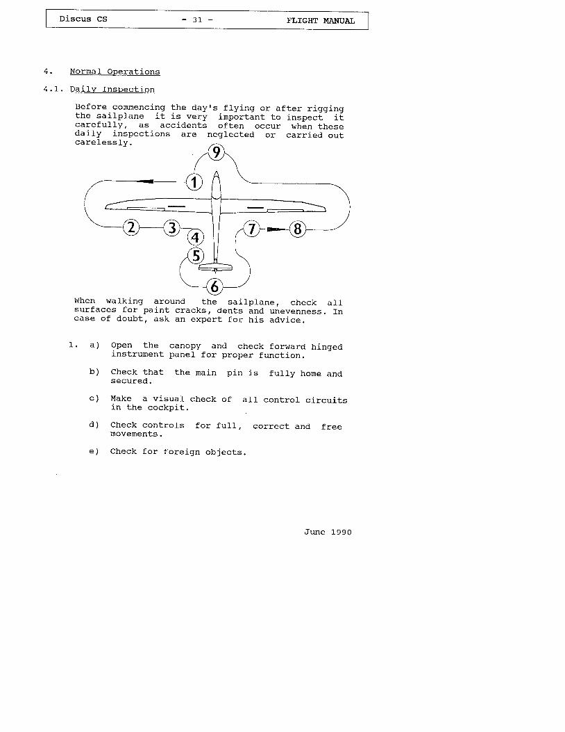
4 . 1 . D a i l v f n s p e c t i o n
Before commenc ing the dayrs f l y ing or a f te r r igg ingthe sai lplane i t is ver! ' imp3rt int to inspeci.- i tcare fu l l y , ds acc idents o f ten occur when theseda i ly inspec t ions are negtec ted or car r ied ou t
q )
b )
d )
e )
1 .
When walk ing around the sai lp lane, check a l -sur faces for paint cracks, dents and unevenness. Incase of doubt , ask an expert for h is advice.
Qnen the canopy and check forward hingedinstrurnent panel for proper function
Check that the rnain pin is fu11y home andsecured.
Make a vi-sual check of all control circuitsin the cockpi t .
Check contro ls for fu l l , correct and f reemovemenEs.
Check for fore ign objects.
June L990
c a r e l e s s l y .
Discus CS - 3 2 - FLIGHT MANUAL
(Dai ly Inspect ion, cont inued)
f ) check main wheel t i re pressure:
U p t o 3 6 0 k g ( 7 9 4 l - b ) A u w : s 0 p s i ( 3 . 5 b a r )u p t o 3 6 0 k g ( 7 9 4 I b ) A U w : 6 4 p s i ( 4 . 5 b a r )
S) Check condi t ion and operat ion of the towhook ( s ) .
2. a ) Check upper and Lower w ing sur faces fo rdamage.
b) C lean and grease water dump va lves .
c ) Check a i le rons fo r p roper cond i t ion and f reemovement.
Check for unusual play by gently shaking thet ra i l ing edge o f the a i le ron .
Check hinges fcr damage.
3 . check a i rb rakes fo r p roper cond i t ion , f i t , andlock i -ng .
4 . a ) Check fuse lage fo r damage, par t i cu la r ly theunders ide .
June 1990
Discus CS - 3 3 - FLIGHT I{ANUAI,
(Dai ly Inspect ion, cont j -nued)
4. b) Check that the stat ic pressure por ts belowthe main spar cut-out and the fuselage tailboom (0 .8 m (31 .5 i . n ) f o rwa rd o f t he l ead ingedge of the f in) are c lear .
Check condi t ion of ta i l sk id (or wheeI ,i f i n s t a l l e d , t i - r e p r e s s u r e 2 . 0 b a r ( 2 8 p s i ) ) .
Check that the fi-n tank dunp hole is c1ear.
If a Total Energy Cornpensatj-on probe is used,mount it and check the l ine (when blowinggently into the probe, variometer shouldr ead t t c l imb t t
) .
c) Check tha t the sp i1 l ho les o f the f j -n tanka r e c l e a r .
d) Check bal last quant i ty in f in tank ( in caseof doubt durnp water) .
7 .
Check hor izon ta l ta i lp lane fo r cor rec tattachment and locking.
check eLevator and rudder for free movement.
Check trai l ing edge of elevator and rudderfo r damage.
Check elevator and rudder for unusual playby gent ly shak ing the t ra i l ing edge.
S e e ( 3 )
s e e ( 2 )
June 1"990
a )
b )
a )6 .
d )
b )
Discus CS - 3 4 - FLIGHT MANUAL
(Da i1y Inspec t ion , con t inued)
Check that the stat ic pressure ports nearthe instrument panel and the Pitot tube inthe fuse lage nose are c1ear . When b lowinggently into the Pitot tube the airspeedind ica tor shou ld recr is te r .
By removing the connectors behind theinstrument panel, water rnay be drained frornP i to t , S ta t i c and Tota l Energy Compensat ionl i n e s .
After heavy landings or after the sai lplanehas been sub jec ted to excess j -ve g- Ioads ,the resonant frequency of the wing shouldbe checked ( the exac t f igure o f th is ser ia lnumber is shown in the last inspectionr e p o r t ) .
Check the entire sai lplane thoroughly forsurface cracks and other damage. For thispurpose i t shou ld be de- r igged.
I f damage is found ( i .e . sur face c racks inthe fuse lage ta i l boorn or ta i lp lane, o r i fdelanination is discovered at the wingroots or at the bearings in the root r ib)the sai lplane must be grounded unti l thedamaqe has been repaired by a qual i f iedperson.
June 1990
4 - J
Discus cS - 3 5 - FLIGHT I.[,AI[UAI,
Pre- f l iqh t Inspec t ion
R e f e r t o c o c k p i t p l a c a r d s . ( S e e c h a p t e r l - . 2 , p a g e 5 )
Take-o f f
4 . 3 . L A e r o t o w
Maximum permitted speed on aerotow
v r : 1 8 o k n / h ( 9 7 k t , 1 1 2 n p h )
U s e t h e c . c . h o o k f o r a e r o t o w , o r , i f i n s t a l l e d ,the nose tovr hook. The Discus has been aerotowedusing hemp and nylon ropes of between 30 and 60n ( 1 0 o a n d 2 0 0 f t ) l e n g t h .
For take-off set tr irn to about one third travelf rom i ts fo rward pos i t ion (w i th the C.G. in a f t rnos tpos i t ion the t r in shou ld be fu l1y noseheavy) .
As the tow rope t ightens apply the wheel brakegently so that the sai lplane does not overrun thecow rope.
For in te r rned ia te to fo rward c .c . pos i t ions theelevator shoul-d be neutral for the ground run; inthe case o f rear C.G. pos i t ions i t i s recommendedduring the ground run that down elevator j .s appl iedu n t i l t h e t a i l l i f t s .
Due to the control circuit geornetry of the ai leroncontrol, sl ightly larger control st ick movements arerequired during the take-off run.
A f t e r l i f t - o f f , a t a b o u t 7 5 t o 9 5 k m r z h ( 4 0 - 5 1 k t ,47 - 59 mph) - depending on the load - the tr irn canbe re-set f or mini-mum el-evator control 1oads.
J u n e L 9 9 0
Discus CS - 3 6 - FLIGHT MANUAL
(Aerotow, cont inued)
NormaL towing speed is in the region of 100 to120 kn/h (54 - 65 kt , 62 - 75 mph) and beth leen 120and 140 kn /h (65 - 76 kL ,75 - 87 nph ) when wa te rbal last is carr i -ed.
To keep station behind the tug only srnall controlmovements are necessary.
Correspondingly greater control movements arerequired when f ly ing the sai , lp lane into the tugrspropel ler s l ip s t ream; fur thermore, ta i lp lanevibration occurs and the airspeed indicator readingvar i -es.
The undercarriage nay be retracted during tow;this is not, however, recommended at low altitude,as changing hands on the control stick could easilycause the sailplane to lose station behind the tug.
When re leasing the tow rope, pul l the yel low gr ipfu11y several t imes and turn only when definitelyc lear of rope.
With st rong crosswind and rear c .G. posi t ion applydown elevator durj.ng the ground run. For other C.G.positions the elevator during the ground run shouldbe neutra l .
For rear C.G. posi t ion t r im heavy nose. For otherpositions the elevator trirn is in the one third ofthe range from the forward position.
June l-990
Discus CS - 3 7 - FLIGHT MANUAI
4 . 3 . 2 W i n c h l a u n c h i n g
Maximum pernitted winch launch speed
Vw : 150 kn/h (81 kt , 93 rnph)
Winch launching is pernittedonly when the C.G. hook is used.
The t r in i s normal ly se t a t a mid-po in t pos i t ion ,fo r rearward C.c . pos i t ions i t shou ld be se t tofu l l y nose heavy .
As the cable t ightens, apply the wheel brake gentlyin order to prevent the sai lplane overruning thewinch cab1e.
Ground run and l i f t off are normal and there is notendency to veer -o f f o r to c l imb excess ive ly s teep lyon leav ing the ground.
Dependj.ng on the seat load the sai lplane is l i f tedo f f w i th the cont ro l s t i ck a lmost fu l Iy pushedforward in the case o f a f t C .c . pos i t ions ands l igh t ly pu1 led back w i th the C.G. in a fo rwardp o s i t i o n .
Af te r c l inb ing to a sa fe he igh t the t rans i t ion to atypical steep winch launch cl imbi-ng att i tude ise f fec ted by eas ing the cont ro l co lumn back s1 igh t ly .
A t normal f l y ing we igh ts , w i thout water ba1Ias t ,the launch speed should not be less than 90 km/h( 4 9 k t , 5 6 m p h ) , a n d w i t h w a t e r b a l l a s t n o t l e s st h a n 1 0 0 t o 1 1 0 k n / h ( 5 4 - 5 9 k t , 6 2 - 6 8 n p h ) .NormaL launch speed is about 100 kmrzh (54 k t , 62nph) , w i th water ba l las t about 115 to 125 kn /h( 6 2 - 6 8 k t , 7 L - 7 7 m p h ) .
At the top of the launch the cable wil l normallyback re lease au tomat ica l l y ; the cab le re leaseshou ld , however , be pu I led f i rn ly severa l t imes toensure tha t the cab le has ac tua l l v qone.
June 1990
Discus CS - 3 8 - FIJIGHT UANUAL
(Winch launching, cont inued)
J u n e 1 9 9 0
Inportant
Winch launching at maximurn perrnit ted al l-upweigh t o f 525 k9 (1157 Ib ) shou l "d on ly beperforrned i f an appropriately strong winch and acab le in per fec t cond i t ion are ava i lab le .
There is not rnuch point in using a winch launchfor a soar ing f l iqh t i f the reLease he igh tg a j - n e d i s l e s s t h a n 4 0 0 n ( 1 3 0 0 f t ) .
The length of the cable should also correspondto th is cond i t ion .
In case o f doubt , reduce a l l -up we igh t to e .g .4 0 0 k g ( 8 8 2 l b ) o r l e s s .
Winch launching with water baLl-ast is notrecornrnended i f the head wind is less than 20k m / h ( 5 . 6 m / / s , 1 1 k t ) .
I t i s exp l i c i t l y adv ised aga ins t w inch launch ingwi th a ta i l w ind .
Discus CS - 3 9 - FLIGHT MANUAL
4 . 4 F r e e f l i q h t
Th is sa i lpane has p leasant f l igh t charac ter is t i csand can be f lown e f fo r t less ly a t a l l speeds, load j -ngcond i t ions ( w i th o r w i thout water ba l las t ) ,con f igura t j -ons and C.G. pos i t ions .
w i th a mid-po j -n t C .G. pos i t ion the speed rangecovered by the tr im is from about 70 km/h to about2 2 o k m / h ( 3 8 t o 1 1 9 k t , 4 3 t o 1 3 7 m p h ) .
F ly ing charac ter is t i cs a re p leasant and thecont roLs are we l l har rnon ized.
Turn reversa l f ron 45o to 45o is e f fec ted w i thoutany no t iceabLe sk idd ing .
Ai lerons and ruder may be used to the l imit ofthe i r t rave l -
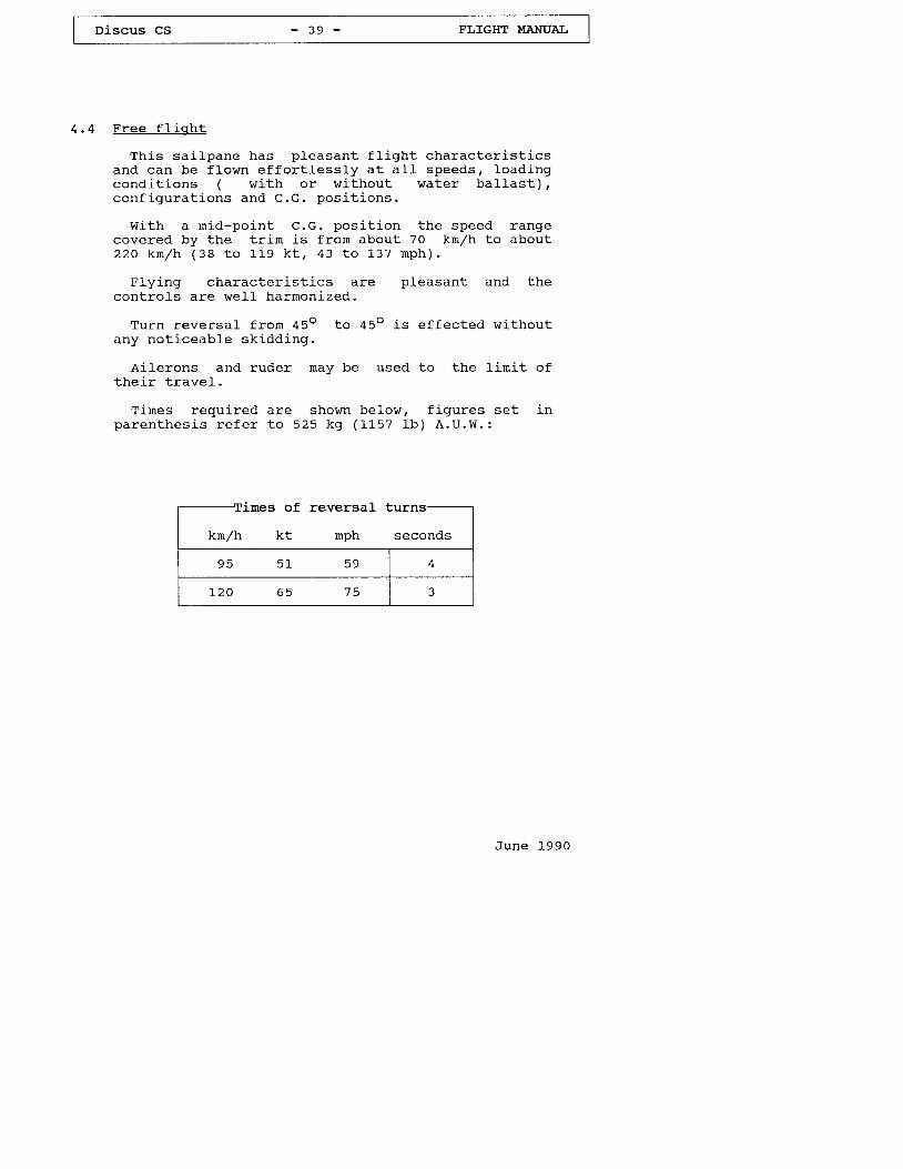
Times required are shown below, f igures set inp a r e n t h e s i s r e f e r t o 5 2 5 k g ( 1 1 5 7 1 b ) A . U . W . :
irnes of reversal
June L990
-r'l_mes or reversar curns-
- -h secondsA r u / r r A L l u P
9 5 5 1 5 9
r20 65 75 3
4.5 Low SPeed Hand l inq and Sta1 l
In order to become famil iar with the Discus we
recommend exploring the low speed and stal1
charac ter is t j . cs a t a sa fe he igh t '
Sta11s should be approached from straight f l ight
and f rom tu rn ing f l igh t (w j ' th appr ( f ,x ' 45" bank) '
S ta I I inq f rom s t ra igh t and 1eve l f l i qh t
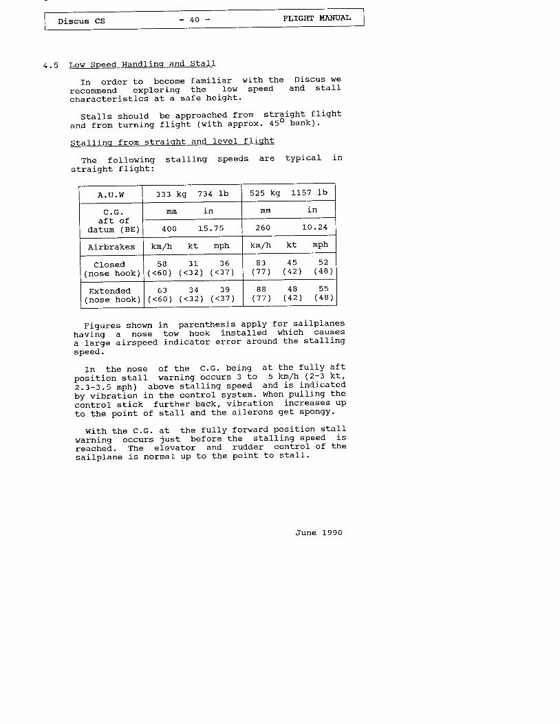
The fo l low ing s ta t l ing speeds are typ ica l in
s t ra igh t f l i gh t :
A . U . W 3 3 3 k g 7 3 4 L b 525 kg l-Ls7 lb
c . G .a f t o f
datun (BE)
nm I N nm
4 0 0 L 5 . 7 5 2 6 0 L O . 2 4
Airbrakes krn/h kt nph kn/h kt mPh
Closed( n o s e h o o k )
5 8 3 1 3 6( < 6 0 ) ( < 3 2 ) ( < 3 7 )
8 3 4 5 5 2( 7 7 ) ( 4 2 ) ( 4 8 )
Extended( n o s e h o o k )
6 3 3 4 3 9( < 6 0 ) ( < 3 2 ) ( < 3 7 )
B B 4 8 5 5( 7 7 ) ( 4 2 ) ( 4 B )
Figures shown in parenthesis apply for .sa i lp lanesnaviig a nose tow hook installed which causesa lar ie a i rspeed indicator error around the sta l l ingspeed.
In the nose of the C.G. being at the fu l ly af tposi t ion sta l l warning occurs 3 to 5 kn/h (2-3 kt 'i .z-2.5 rnph) above sta lJ- ing speed and is ind icatedby vibration in the control systen. When pu1Ii 'ng thec6ntrol stick further back, vibration increases upto the point of stal1 and the ailerons get spongy'
wi th the c.G. at the fu l ly forward posi t ion sta l lwarnj.ng occurs just before the stall ing speed isreached. The elevator and rudder control of thesai lp lane is normal up to the point to s ta l l - '
June L99O
Discus cS - 4 1 - FLIGHT MANUAI
(Sta l l ing f rom s t ra igh t and 1eve l f l i gh t ,c td . )
when reach ing a s ta l led cond i t ion w i th the c .G. a tan a f t pos i t ion the sa i lp lane may drop a w ing bu tusua ly the w ings can be he ld leve* .
When the c .c . i s fo rward , the sa i lp lane w i l ls imp ly s ta l l s t ra igh t ahead w i th fu1 l a f t s t i ck .
Trans i t ion in to a normal f l iqh t cond i t ion isperformed by releasing the back pressure on thecont ro l s t i ck and, i f necessary , app ly i -ng oppos i terudder and a iLeron .
Turn ing f l iqh t s ta l l s
When approaching a stal l from a coordinated 45obanked turn with the control st ick ful ly pul led backthe sa i lp lane e i ther cont inues to f l y in a s ta l ledcond i t ion or i t d rops a w ing abrupt ly .
w i th the c .c . a t fonnrard pos i t ion and the cont ro ls t i ck fu I Iy pu l led back i t s imp ly s ta l l s .
Trans i t ion in to a normal f l igh t cond i t ion isper fo rmed by appropr ia te use o f con t ro ls .
Sp ins
r n t h e c a s e o f a f t C . G . p o s i t i o n , a p p l i c a t i o n o ffu l . I ruder when the sa i lp lane i -s s ta l led w i l lp roduce a sp in .
June 1990
Discus cS - 4 2 - TI,IGHT MANUAL
( S p i n s , c t d . )
wi th the c.G. an af tmost posi t ion osci l la t ions inpi tch occur dur ing a sPin.
I f a i leron is appJ. ied in the d i rect ion of the spinthe pitch attidude steepens and the rate of rotationincreases.
Foltowing the standard recovery procedure the lossof height during recovery from a spin isapproximately 50 to B0 m (164 lo 262 f t ) measuredfrom the point at which recovery is init iated to thepoint at which hor izonta l f l ight is regained.
Recovery speed is between about l '20 and 190 km/h(65 and 1 .03 k t , 75 and 118 nph ) .
A safe recovery frorn the spin is effected byfollowing the standard recovery procedure:
a) apply opposi te rudder, i .e . against d i rect ionof sp in
b) short pause
c) ease the control colurnn forward unti l rotationceases and the airf low is restored
d) centra l ize rudder and pu1I gent ly out of theresul t ing d ive.
wi th the c.G. at the fu l ly forward posi t ion spinscannot be induced, but, depending on the use ofcontro ls a spi ra l d ive rnay develop. The sai lp lanewill quickly recover from thj 's condj't ion by normaluse of opposi te contro ls .
June 1990
Discus cS - 4 3 - FLIGHT MANUAI
4 . 6 High Speed Fl- iqht
When f lying at high speeds up to V"ro = 25O krn (135k t , 155 rnph) the sa i lp lane is we l l c i j f i t ro1ab le .
Fu l I de f lec t ion o f con t ro l sur faces may on ly beu s e d u p t o V O : 2 O O k m / h ( L 0 8 k t , 1 2 4 n p h ) .
A t Vwn : 25O km/h ( l -35 k t , 155 nph) on ly I /3cont ro l fdd de f lec t ions are permi t ted . Avo idespecial ly sudden elevator control movernents.
In s t rong tu rbu lence, i . e . in wave ro to rs ,thunders to rms, v is ib le wh j - r l w inds or when c ross ingrnounta in r idges , the speed in rough a i r Voo : 200knr /h (108 k t , I24 rnph) must no t be exceeded^ . - '
Wi th the C.G. in rearwand pos i t ions the cont ro lcolumn rnovement from the point of sta11 to max.per rn iss ib le speed is re la t i ve ly s rna I1 , though thechange in speed wil l be noticed througha perceptible change in control column Ioads.
The airbrakes may be extended up to V*o = 250k m / h ( L 3 5 k t , 1 5 5 m p h ) , h o w e v e r , t h e y s h o u 1 d " 5 n l y b eused at such high speeds in emergency or when themaximum perrnit ted airspeeds are being exceededinadver tend ly .
As the airbrakes are very effect ive thedece lera t ion fo rces are cons iderab le i f thev areextended suddenly.
Therefore i- t must be ensured that the harness ist ight and that the control colurnn is notinadvertently rnoved when the airbrakes are extended.
Avoid loose object in cockpit.
June 1990
Discus CS - 4 4 - FLIGHT MA$UAL
(High Speed F l igh t , c td . )
I t should also be noted that with the airbrakesextended the sai lplane should be pul led out lessabrupt ly than w i th re t rac ted a i rb rakes (see sec t ion2 . 5 , l o a d f a c t o r s ) .
A dive with the airbrakes ful ly extended isl irnited to an angle to the horizon oi about 30o atmaximum perrnit ted al l-up weight and to about 45owi thout water ba l las t a t speeds o f approx imate ly 250k m / h ( 1 3 5 k t , 1 5 5 m p h ) .
June 1990
Discus cs - 4 5 - FLIGHT I,IANUAL
4 . 7 F l y i n q w i t h w a t e r b a l l a s t
The water bal last tanks are integral cornpartmentsin the w ing D nose.
The tanks are to be f i l led with clear water onlytrough a round opening with a strainer on the uppersur face o f the w ing D nose.
. The .plugged-in f i l ler caps are withdrawn byinsert ing the tai lplane r igging screw in their 6 rnrn(O.24 in ) fe rna le th read. The th read ho le in the capalso serves for ventj .ng the tank quickly and nusltherefore be kept clear. In addit ion both tanks arealso vented by a tube running from the highest pointof the tank through the wing to the underside of thewing t ip . The vent ho le in the f i l1er cap maytherefore be taped t ight when placing the t ip of aful l wing on the ground. Water then wil l stopescaping through the venting tube as soon as an ai ipocket has formed at the highest point of the tankat the root r ib. The tape covering the f i l1er caphole should be removed before take-off so that theba l las t tank is d ra ined o f f in the shor tes t t ine .
Dumping the water bal last takesminutes f ro rn fu l1 tanks .
about four to f ive
June 1990
Capacity ofl i ters U . S . c a l . I m p . c a l .
t o t a l 1 8 4 4 8 . 6 4 0 . 5
l e f t 9 7 2 5 . 6 2 i , . 3r i g h t , a 7 2 3 . O I g . 2
Discus cS - 4 6 - FLIGHT I'{ANUAI,
( F l y i n g w i t h w a t e r b a l l a s t , c t d . )
When f i l l ing the tanks bear in rnind the weight ofthe pi lot and ensure that the maximurn permittedweigh t i s no t exceeded (see load ing tab le , sec t ion2 . 7 t p a g e 2 2 ) .
Both tanks should be f i l led with about the sameamount of water to prevent lateral imbalance. (withfu1 l w ing tanks the i r d i f fe ren t capac i ty i s hard lyperceptible as the excess weight is si tuated neart h e r o o t r i b ) .
When taking off with part ly ful l bal last tanksensure that the wings are held IeveI in order toal low the water to be equafly distr j .buted so bothwings are ba l l "anced.
Because of the additional weight in the wings thewingtip runner should continue running as long aspossib le dur ing the launch.
Thanks to the integral bulkheads in the bal lasttanks there is no perceptibl-e movement of the waterba l las t when f l y ing w i th par t ia l l y fu l I tanks .
When f l y ing a t max imum permi t ted A.U.W. the Lowspeed and s ta l l behav iour o f the sa i lp lane iss l igh t ly d i f fe ren t f rom the f l igh t charac ter is t i cswi thout water ba l las t . The s ta11 i -ng speed increases( s e e s e c t i o n 4 . 5 ) , a n d f o r c o r r e c t i o n s o f t h e f l y i n gatt i tude larger movements of the control surfacesare requ i red . A1so, fo r recovery f rom a s ta l ls l igh t ly more he igh t i . s necessaryf l y ing a t t i tude .
to regain normal
June 1-990
Discus CS - 4 7 - FLIGHT MANUAL
( F l y i n g w i t h w a t e r b a l l a s t , c t d . )
Water bal l-ast is dumped through an opening on thelower wing surface near the root r j-b.
The durnp valve mechanism is hooked-upautorna t ica l l y when the w ings are r igged.
In the unl ikely event of the tanks enptyingunevenly or only one of thern ernptying (recognized byhav ing to app ly up to 5oZ oppos i te a i le ron fo rn o r m a l f l y i n g a t t i t u d e ) , i t i s n e c e s s a r y t o f l ysornewhat faster to take into account the increasedweigh t and a lso to avo id s ta l l ing the sa i lp lane.
I f , desp i te th is , the sa i lp lane shou ld en ter asp in w i th a very f la t ang le to the hor izon , then,for spin recovery according to the standardprocedure , fu11 fo rward s t i ck i s requ i red and theairbrakes rnust be extended.
When land ing , be prepared to veer o f course , dsthe heav ie r w ing w i l l touch down somewhat earL ie r .
F in Tank
The forward travel of the center of gravity,caused by water bal last in the wings, f ldy becompensated by carryi-ng water bal last in a f in tank,thus regaining optimum performance in circl ingf l i g h t .
For instruct ions how to use the f in tank refer tot h e f o l l o w i n g p a g e s : 2 2 a , 2 2 b , 2 2 c , 4 7 a , 4 7 b .
J u n e 1 9 9 0
D i scus CS
Water ba l las t in the f in tank
The water tank is an integral compartment in thef i n w i t h a c a p a c i t y o f 6 . 5 k g ( 6 . 5 l i t e r s , I . 7 2U . S . G a 1 . , L . 4 3 I n p . c a l . ) .
The f in tank is f i11ed by connect ing one end o f af lex ib le p las t i c tube (ou ter d j -ameter I mm (0 .31in ) ) to a water conta iner , i t s o ther end is inser tedi n t o t h e f i l l e r t u b e ( i n t e r n a l d i a m e t e r 1 0 n m ( 0 . 3 9in ) ) p ro t rud ing f rom the gap o f the rudder on top o fthe f in . The f i l l e r tube is access ib le w i th thehor izon ta l ta i lp lane in p lace or renoved.
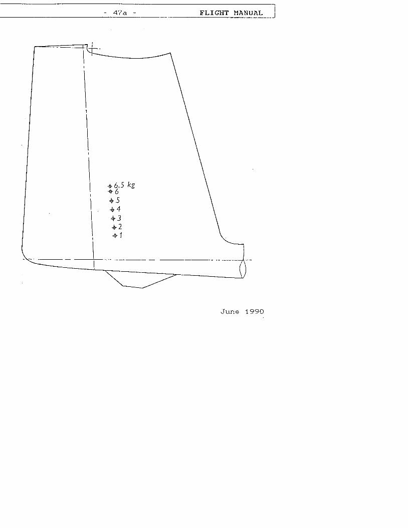
S i x s p i 1 1 h o l e s , o n e f o r e a c h k g ( L t r . ) b a l l a s t ,p lus a seventh fo r the rnax imum capac i ty 6 .5 kg(L t r . ) on top o f the tank , a l l p roper ly marked, a reloca ted on the r igh t s ide o f f in (as shown in theacompany ing ske tch) . These ho les are impor tan t asa l ra te r -gauge.
The nurnber o f sp i1 l ho les to be c losed w i th a tapebefore the tank is f i l Led , depends on the we igh t o fthe ba l las t requ i red to compensate fo r the water int h e w i n g t a n k s ( s e e c h a p t e r 2 . 7 , p a g e 2 2 ) .
A lways taped c losed one ho le lessr e q u i r e d , m e a s u r e d i n k g ( L t r ) .
than the weight
Vent ing o f6 . 5 k g ( L t r .
the fin tank is trough the) hole and t rough the f i l Ier
uppermosctube.
Examnle :
I f a b a l l a s t w e i g h t o f 3 k g ( L t r . ) i srequ i red , on ly the lower two ho les aretaped c losed, aDy excess ive water the
escapes t rough the th i rd hoLe.
4 7 a FLIGIIT }IANUAL
\
I
\
I
\
I
\
I
J u n e 7 9 9 | . .
Discus CS - 4 7 b - FLIGHT MANUAIJ
(Water ba l las t in the f in tank , c td . )
Water bal last is durnped from the f in tank throughan opening on the underside of the fuselage oppositeto the rudder
The f in tank dump val-ve is l inked to the durnpingmechanism of the wing tanks such that al l threetanks always open sirnultanously.
Dunping water bal last frorn a ful1 f in tank takesa b o u t 2 t o 2 . 5 r n i n u t e s , i . e . h a l f o f t i m e r e q u i r e dfor the w ing tanks .
Dunping water bal last fron the f in tank thereforej.s al,ways quicker than f rom the wing tanks.
June 1990
(F ly ing w i th water ba l las t , c td . )
Important
l - . on longer f l tgh ts a t tempera tures near ooc (32oF)
hrater bal last rnust be dunped in any case when
reach ing a te rnpera ture o f 2 "c (36"F) '
2 . There is l i t t le po in t in us ing much water ba l las t
i f the average rate of cl imb expected does not
exceed I .5 m/s (295 f t /m in) . The sarne app l ies to
f l ights in narrow thermals requir ing high angles
o f bank .
3 . Before an o f f - f ie ld land inq water ba l las t shou ld
always be dunPed.
4. on no account whatsoever must the sai lplane ever
be parked w i th fu1 l ba l las t tanks , because.o f the
d.anler of them freezing up. Before the sai lplane
is parked dra in o f f a l l water comple te ly , remove
the f i I le r caps and a1 low the tanks to d ry ou t '
5 . Before the water tanks are f i11ed, check w i th the
durnp valves opened that both drain p1uSl open'
move and c lose s imu l taneous ly . Leak ing (d r ipp inq)
dump valves are avoided by cleaning and greasing
the valve seats and drain plugs (with the valves
open) , then, w i th the va lves c losed, the dra in
plug= are pul led in posit ion with the threaded
too l used to a t tach the ta i lP lane.
6 . Never p ressur ize the tanks , fo r ins tance by
f i l l i ng d i rec t l y f rom the water hose; water
should alwaYs be Poured j-n.
7 . Before the f in tank is f i l ted , check tha t those
sp j . l l ho les no t be ing taped c losed are c lear '
June 1990
Discus CS - 4 9 - FLIGHT I,IANUAL
4 . 8 c l o u d F l y i n g
Th is sa i lp lane is su f f i c ien t ly robus t and s tab lefo r c loud f l y ing . I t i s s i rnp le to cont ro l and iss tab le in a tu rn .
Cer ta in bas ic ru les must be observed however .
Under no circurnstances may the speed l ini tat ionsbe exceeded.
It is recommended that the ai-rbrakes be extendedfu11y i f the speed bu i lds up to l -30 km/h (70 k t ,81 nph) o r i f more than 29 are pu l1ed.
The addit ional equiprnent required for cloud f lyingi s t o b e o b s e r v e d . ( S e e c h a p t e r 2 . 3 b , p a g e 1 7 ) .
FLv inq a t tenpera tures be low f reez inq po in t
w h e n f l y i n g i n t e m p e r a t u r e s b e l o w O o c ( 3 2 o F ) , ( a sin long wave or during the winter rnonths) i t ispossible that the usual ease and smoothness of thecont ro l c i rcu i ts i s reduced.
Ensure tha t aLL cont ro l e lements a re f ree f rommoisture so that there is no danger of them freezi-ngso l j -d . Th is app l ies espec ia l l y to the a i rb rakes .
It has been found benefi-cial to cover the matingsur faces o f the a i rb rakes w i th Vase l ine a long the i rfu l l leng th so tha t they cannot f reeze so l id . Movethe cont ro l sur faces occas iona l l y .
When f l y ing w i th water ba l las t no te thei n s t r u c t i o n s i - n s e c t i o n 4 . 7 .
June 1990
only pernitted without water ballast.
Discus CS - 5 0 - FLIGHT MANUAL
(F ly ing at temperatures belor" r f reezing point ,c td. )
Warning
The polyester coating on this sailplane is knownfrom many years experience to become very britt le atIow temperatures.
Particularly when flying in long wave at al"t idudesabove abou t 6000 m (app rox . ^20000 f t ) , whe retemperatures of below -30"C (-22"F) rnay occur , thegel coat, depending on its thickness and thestressing of the a i rcraf t rs components, is prone toc rack ing .
In i t ia l ly , cracks wi l l on ly appear in thepolyester coating, however, with time and changingenvironment, cracks can reach the epoxy/glassrnatrj-x. Cracking is obviously enhanced by steepdescents fron high altitudes at associated very lowtemperatures.
Therefore, for the preservat ion of a propersurface finish free from cracking, the manufacturerst rongly advises against h igh a l i i tude f l ights wiFhassociated temperatures of c lear ly below -2OoC( - 4 0 F ) .
A steep descent with the airbrakes extended shouldonly be conducted in case of emergency.
June L990
Discus cS - 5 1 - - FLIGHT T.IANUAL
4 . 1 0 R e s t r i c t e d A e r o b a t i c s
The Discus CS is perrnittedfo l lowing aerobat ics maneuvers:
a) Ins ide Loopsb ) sp ins
to carry out the
c ) S ta l l ed Tu rnd) Lazy Eight
Ins ide Loop
Enter the maneuver a t a speed o f 180 kn /h (97 k t ,3-12 mph) IAS. Speed during recovery from them a n e u v e r : A p p r o x . 1 7 0 k n / h ( 9 2 k t , 1 0 6 m p h ) .
S p i n s
Sp ins are on ly poss ib le when the C.G. pos i t ion isa f t . En ter the sp in f ro rn a s ta l1 by appty ing fu l lrudder and w i th a i le rons neut ra l . Ho ld the s t i ckhard back while spinning. Recover from the spin byapplying opposite rudder and easj"ng the st ickfo rward w i th the a i le rons neut ra l . Recovery speed isabout l -4o kn /h (76 k t , 87 mph) . I f spun w i th theC . G . a t t h e f u l 1 y a f t p o s i t i o n , t h e s p i n w i l lcontinue for approxirnately half a turn afterrecovery ac t ion is in i t ia ted .
Sta I led Turn
Enter the maneuver at speed of 1-60 km/h (86 kt,99 mph) . Whi le c l inb ing ver t i ca l l y 1e t the w ingwhich wil l be on the inside of the turn drag andthen a t about 140 kn /h (76 k t , 87 nph) app ly rudderin the direct ion of the dragging wing in order toprevent a distorted maneuver. Speed during recoveryf rom the maneuver : Approx . 150 kn /h (81 k t , 93 nph) .
Lazv E igh t
Enter the maneuver a t a speed o f 160 knr /h (86 k t ,99 mph) . A f te r pu l l ing up in a 45o c l i rnb en tera tu rn a t about 120 kn /h (65 k t , 75 nph) . Recoverys p e e d : A p p r o x . 1 5 0 k n / h ( 8 1 k t , 9 3 r n p h ) .
June 1990
Only permitted without water
Discus CS - 5 2 - FLIGHT MANUAL
4.11 Approach and Land inq
Norrnal approach speed with airbrakes fuIIyextended and with the undercarr iaqe lowered is 95km/h (51 k t 59 rnph) and a t max imum a l l -up we igh t115 kn /h (62 k t , 71" mph) . In th is conf igura t ion theg l i d e a n g l e i s a p p r o x i n a t e l y 1 : 5 . 5 .
The airbrakes open srnoothly - they are verye f fec t i ve . There is no percept ib le change o f t r i rn .
S l ide s l ipp ing is we l l con t ro l lab le and can beused as an e f fec t i ve land j .ng a id , w i th the a i rb rakesex tended as we11.
At rninimum speed touch dolun is tai l f j . rst.
The whee l b rake works weI l .
To avoid a J-ong landing run make sure that thesai lplane touches down at minimuin speed (about 70k n / h , 3 8 k t , 4 3 r n p h ) .
A t a touch down speed o f 90 km/h (49 k t , 56 nph)i n t e a d o f 7 0 k n r z h ( 3 8 k t , 4 3 n p h ) , t h e k i n e t i cenergy to be dissipated by braking is increased bya fac to r o f 1 .65 and there fore inc reases the Lenqthof the ground run considerably.
For o f f - f ie Id land ings a lways ex tendthe undercarr iaqe.
J u n e L 9 9 0
Discus cs - 5 3 - FLIGHT MANUAL
5. R iqq inq and De- r igq ing
5. 1 R ic rq inq
The sai lplane can be r igged by two persons i fa wing stand is used under the wj-ng t ip.
A11 w ing and ta i lp lane r igg ing f i t t ings shou ld becleaned and crreased.
Wi-ngs
Unlock the airbrakes and set the water bal lastje t t i son ing knob in the fo rward (c losed) pos i t ion .Inser t the le f t w ing .
It is irnportant that the helper on the wing t ipshou ld concent ra te on l i f t ing the t ra i l ing edge o fthe wing more than leading edge, so that the rearwing attachment pin does not force the swivelbearing on the fuselage down and out of al ignrnent.
Check that the spar stub is Located correctly onthe fa r s ide o f the fuse lage ( i f necessary t i l t thefuselage or move the wing gently up and down to helpi t h o n e ) .
Check that the angular levers at the root r ib areproperly inserted in the funnels on the fuselage.
Push in the rna in bo l t approx . 30 run (1 .2 in ) sothat the wing is is prevented from sl idi-ng out bythe GRFP cover over the forward wing rnounting tube.The w ing can now be p laced on the s tand.
J u n e 1 9 9 0
Discus CS - 5 4 - FLIGHT MANUAL
( R i g g i n g , c t d . )
Insert the r ight wing.
The procedure is the same as for the left wing.
I f i t i s d i f f i cu l t to push in the w ing fo r thel a s t 1 0 o r 2 0 m n ( 0 . 4 o r 0 . 8 i n ) , r e m o v e t h e m a i nbolt again and draw the wings together with ther igg ing lever .
Make sure that the airbrake operating lever issl ightly pu11ed back as otherwise the overcenteringforces or the airbrake locking systen wj. l l dr ive thewings apart by some rni l l i rneters.
F ina l l y , push the rna in bo l t fu l l y home and secureit by i ts handLe with the cowling safety pin on thef u s e l a g e s i d e .
June L990
Discus CS - 5 5 - FI,IGHT I.'ANUAL
(Rj .gg inq , c td . )
Hor izon ta l " ta i lp lane
Take the round-headed r igging tool (from thecockpit pocket) and screw it into the frontta i lp lane loca t ing p in in the lead ing edge o f thef i n
s l ide the ta i lp lane a f t on to the two e leva toractuating pins. Then pul1 the roundheaded r iggingtool and i ts pin forward, seat the front of thetai lplane and push the pin ful1y home into theta i lp lane f i t t ing . Remove r igg ing too l .
The pin must notof the leading
protrude j-n frontedge of the f in .
check whether elevator operating pins are real lyloca ted by mov ing the e leva tor .
After r iqr{ i"ncl
Wi th the a id o f a he lper check cont roLs fo r fu l land free novernent in the correct sense.
Use tape to sea l o f f the w ing / fuse lage jo in t , theopening for the front tai lplane attachment pin andthe jo in t be tween f in and ta i lp lane.
Sea l ing w i th tape is benef ic ia l in te rms o fperforrnance and i t also serves to reduce the noj,seI e v e l .
J u n e 1 9 9 0
Discus CS - 5 6 - FLIGHT MANTIAL
5 . 2 D e - r i q q i n g
Before the sa i lp lane is de- r igged, remove sea l ingc a p e s .
Hor izon ta l ta i l -p1ane
Wi thdraw f ron t a t tachment p in w i th r igg ing too l ,l i f t the tead ing edge o f the s tab i l i zer s1 igh t1y ,s l ide ta i lp lane fo rwards and o f f .
Winqs
Unlock the a i rb rakes , se t water ba l las t va lvecont ro l to r rc losedt t ( fo rward) and re rnove sa fe ty p inf rom the rna in bo l t hand le .
with a helper on each wing t ip pul l out the rnai_nbolt and withdraw the r ight wj_ng, gently rocking i tbackwards and forwards i f necessarv.
Then remove the left wincr.
June 1990
Discus cS - 5 7 - FLIGHT T.TANUAL
5.3 Storaqe. Hangar inq and Transpor t
The sai lplane should always be hangared or kept inwe l l ven t i la ted cond i - t ions .
I f i t i s kep t in c losed t ra i le rs there must beadequate vent i l -a t ion .
The sa i lp lane must no t be sub jec ted to loads whennot in use , espec ia l l y in the case o f h igh a inb ien tternperatures.
As the w ings have a th in a i r fo i l sec t : -on i t i sirnportant that they are well supported:
Leading edge down, with support at the spar rootsa n d a p p r o x . 3 . 3 n ( 1 0 . 8 f t ) f r o r n t h e v r i n g t i p i nw ing c rad les o f cor rec t a i r fo i l sec t ion .
The fuselage can rest on broad cradLe just forwardo f t h e C . G . h o o k a n d o n i t s t a i l s k i d ( o r w h e e l ) .
The tai lplane should be kept leading edge down intwo c rad les o f cor rec t a i r fo i l sec t ion , about L .0n ( 3 . 3 f t ) a p a r t .
On no account should the tai lplane be supportedby i t s f i t t ings in the t ra i le r .
In the case of sai lplanes vrhich remain r iggedpermanently iE j-s important to ensure that themaintenance program includes rust prevention for thef i t t ings o f the fuse lage, w ings and ta i lp lane.
Dust covers shou ld be regarded as essent ia l fo ra h igh-per fo rmance sa i lp lane.
I f the sai lp lane is being pushedit should not be pushed at the wing tips but as
near to the fuselage as possib le.
J u n e 1 9 9 0
F A
Di-scus cs - 5 8 - FLIGHT I,IANUAL
Car ing fo r the sa i lp lane sur face
For cleaning and care we recommend:
Water with or without washing agents withusuaL add i t i ves , po l i sh and po l i sh na ter ia ls .
Pet ro l and a lcohoL may be used fo r a shor tt i rne on1y .
Not recommended are thinners of al l ki .nds.
N e v e r u s e c h l o r i d e h y d r o g e n ( i . e . T r i , T e t r a ,P e r , e t c . ) .
The canopy shou lc l be c leaned w i th "P1ex j .k la r r r ,I t M i r r o r G I a z e r r , o t w i t h a s i m i l a r p l e x i g l a s sc leaner and on ly i f necessary , w i th warmwater. The canopy should be wiped down onlywi th a c lean so f t chamois lea ther o r a verys o f t m a t e r i a l .
Never rub the canopy when it is drY.
This sa i lp lane, l i ke any o ther , shouJ-d bepro tec ted f rom the wet .
I f water has found a way in , the sa i lp laneshould be stored in a dry environment and thecomponets turned frequently to el irninate thewater .
The sa i lp lane shou ld no t be exposedunnecessarity to intense sunl ight or heat andshou ld no t be sub jec ted to cont inua l loads ina mechan ica l sense.
J u n e L 9 9 0
Discus CS - 5 9 - FLIGHT MANUA],
(Car ing fo r the sa j - Ip lane sur face , c td . )
A l l ex te rna l por t ions o f Lhe sa i lp lane exposedto sunl ight must be painted whi-te, except theareas for the regJ.strat ions numbers and(opt iona l ) an t i -co l l i s ions rnark ings .
Colours other than white can lead to the GRFPor CRFP overheating in direct sunl ight,result ing in weakening of the structure.
June 1990
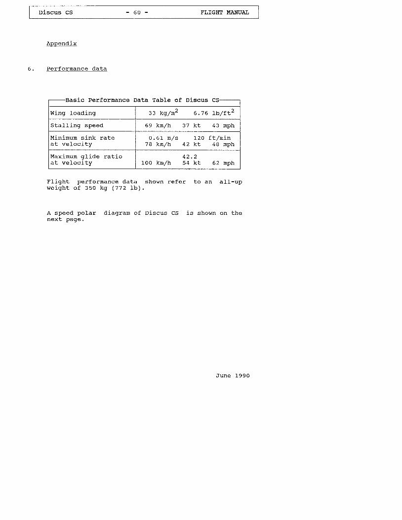
I Discus CS - 60 - FLIGHT I'{ANUAI I
Appendix
6 . Per fo rmance da ta
LscBasic Perfornance Data Table of Di.scus
Wing load ing z3 kg /m2 6 .76 rb / f t z
Sta l l ing speed 69 kn/h 37 kt 43 nph
Minirnum sink rateat ve loc i ty
0 . 6 1 m / s 1 2 0 f t l n i n78 kn/h 42 kt 48 nph
Maximum gl j .de rat ioa t ve loc i ty
1 Z - Z
100 kmrzh 54 kt 62 nph
F l igh t per fo rmance da ta shown re fe r to an a l l -upw e i g h t o f 3 5 0 k g ( 7 7 2 I b ) .
A speed polar diagram of Discus CS is shown on thenex t page.
June 1990
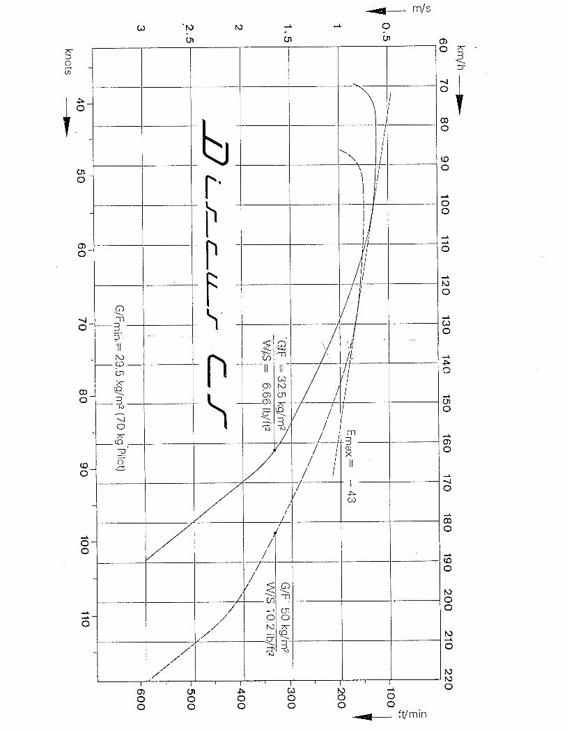
t_ m/s
6o
{ + / - : ^_ l v i l i l t l
ino 4 -
"1
f
- l lo l
w
I@o
(oo
oo
o
No
(r)
o
s
J
UIo
o)o
iO
@O
(oo
NoO
t\)
o
N19o
-'l-l
:f)=, I I
N)
in-/<(o
=J
N
!
ra)
fr)e
oo
tso
Oo
Aoo
Oloo
o)oo